

CS9236
Single-Chip Wavetable Music Synthesizer
Features
• Single low-cost device includes MIDI
controller, synthesis engine, effects
processing, RAM, and sample ROM
• General MIDI (GM) compliant
• 32-note polyphony at 44.1kHz rate
• Independent reverb and chorus levels
for each MIDI channel
• +3.3V supply, +5V tolerant inputs
• Fully static power-down capability
• Simple to design in - Serial MIDI in,
Stereo digital audio out
• Digital audio output directly Interfaces
with the CS4236B/37B/38B and
CS4333
General Description
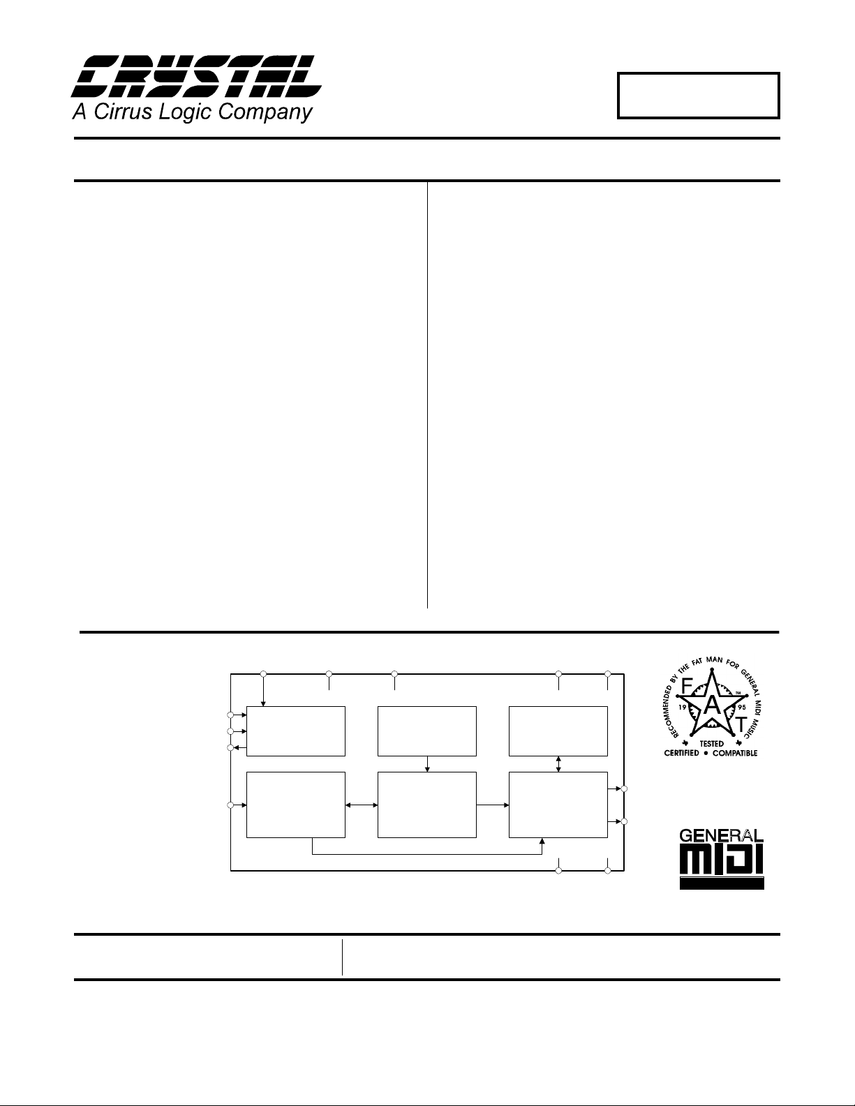
The CS9236 is a complete General MIDI wavetable music synthesizer on a single integrated circuit. The MIDI
interpreter, synthesis engine, effec ts processing, and all
RAM and ROM memories (including the wavetable sample ROM) are included on-chip. This all-digital device
receives a standard serial MIDI data stream, and output s
a stereo 16-bit digital audio stream at 44.1kHz. The
CS9236 digital audio output is directly compatible with
the Crystal CS4236B/37B/38B multimedia CODECs,
and with the CS4333 DAC.
The CS9236 features a high quality General MIDI sample set including 128 melodic instruments and 47
percussion sounds. The synthesis engine is capable of
generating up to 32 simultaneous notes. Digital reverberation and chorusing effects are included on-chip.
The CS9236 is the ideal low-cost General MIDI synthesizer solution for a number of applications, including
multimedia PCs, game machines, karaoke , and low-cost
musical instruments and MIDI sound modul es.
ORDERING INFORMATION
CS9236-CL 0° to 70
CS9236-CQ 0° to 70°C 44-pin TQFP
°C
28-pin PLCC
____
PDN
MCLK5I
XTAL3I
XTALO
MIDI_IN
Clock Generation
& Control
MIDI Interpreter Synthesis Engine Effects Processor
Preliminary Product Information
Crystal Semiconductor Corporation
P.O. Box 17847, Austin, Texas 78760
(512) 445 7222 FAX: (512) 445 7581
http://www.crystal.com
____
RST
TEST
Sample ROM Effects RAM
This document contains information for a new product. Cryst al
Semiconductor reserves the right to modi fy th is product witho ut notic e.
Copyright Crystal Semiconductor Corporation 1997
(All Rights Reserv ed)
VDD1
GND1
VDD2
SOUT
LRCLK
GND2
DS214PP11
MAY ‘97
1

TABLE OF CONTENTS
RECOMMENDED OPERATING CONDITIONS .............................................................................4
SWITCHING CHARACTERISTICS ..................................................................................................4
DIGITAL CHARACTERISTICS ........................................................................................................6
ABSOLUTE MAXIMUM RATINGS .........................................................................................6
GENERAL DESCRIPTION .................................................................................................................7
CS9236/CS4236B/37B/38B Typical Connections ......................................................................7
CS9236/CS4333 Typical Connections ........................................................................................8
CS9236 Clocks and Timing Generation ....................................................................................9
Power-Down Modes .....................................................................................................................9
Digital Audio Interface ................................................................................................................9
Reset ..............................................................................................................................................9
GENERAL MIDI (GM) MELODIC INSTRUMENTS AND PERCUSSION SOUNDS ..............10
MIDI IMPLEMENTATION ...............................................................................................................13
Channel Voice Messages ...........................................................................................................13
Control Change Messages .........................................................................................................13
Registered Parameters ......................................................... ........................................... ..........13
Channel Mode Messages ...........................................................................................................13
System Realtime Messages ........................................................................................................14
System Exclusive Messages .......................................................................................................14
Message Definitions ...................................................................................................................16
Channel Voice Messages.....................................................................................................16
NOTE ON..........................................................................................................................16
NOTE OFF ........................................................................................................................16
PROGRAM CHANGE......................................................................................................17
CHANNEL PRESSURE (Channel Aftertouch)................................................................17
PITCH BEND CHANGE ..................................................................................................18
Control Change Messages...................................................................................................19
MODULATION WHEEL (CONTROLLER 1)................................................................19
DATA ENTRY (CONTROLLERS 6 and 38)...................................................................19
VOLUME (CONTROLLER 7).........................................................................................19
PAN (CONTROLLER 10)................................................................................................20
EXPRESSION (CONTROLLER 11)................................................................................20
DAMPER PEDAL/SUSTAIN (CONTROLLER 64)........................................................20
SOSTENUTO (CONTROLLER 66)..................................... ............................................21
EFFECT 1 DEPTH/REVERB SEND LEVEL (CONTROLLER 91)...............................21
EFFECT 3 DEPTH/CHORUS SEND LEVEL (CONTROLLER 93) ..............................21
REGISTERED PARAMETER NUMBER (RPN) (CONTROLLERS 100 and 101).......22
Registered Parameters.......................... ........ ......................................................................23
PITCH BEND SENSITIVITY (RPN 00)..........................................................................23
FINE TUNING (RPN 01)..................................................................................................23
COARSE TUNING (RPN 02)...........................................................................................24
Channel Mode Messages.....................................................................................................25
ALL SOUNDS OFF (Controller 120)...............................................................................25
RESET ALL CONTROLLERS (Controller 121)..............................................................25
ALL NOTES OFF (Controller 123)..................................................................................25
OMNI MODE OFF (Controller 124) ................................................................................25
OMNI MODE ON (Controller 125)..................................................................................26
MONO MODE ON (Controller 126) ................................................................................26
POLY MODE ON (Controller 127)..................................................................................26
System Real Time Messages...............................................................................................27
CS9236
2 DS214PP11

ACTIVE SENSING...........................................................................................................27
SYSTEM RESET..............................................................................................................27
System Exclusive Messages................................................................................................28
ENABLE RECOGNITION OF MIDI CHANNEL PRESSURE......................................28
DISABLE RECOGNITION OF MIDI CHANNEL PRESSURE.....................................28
ENABLE TEST TONE.....................................................................................................29
DISABLE TEST TONE....................................................................................................29
PIN DESCRIPTIONS ..........................................................................................................................30
CS9236
DS214PP11 3
CS9236
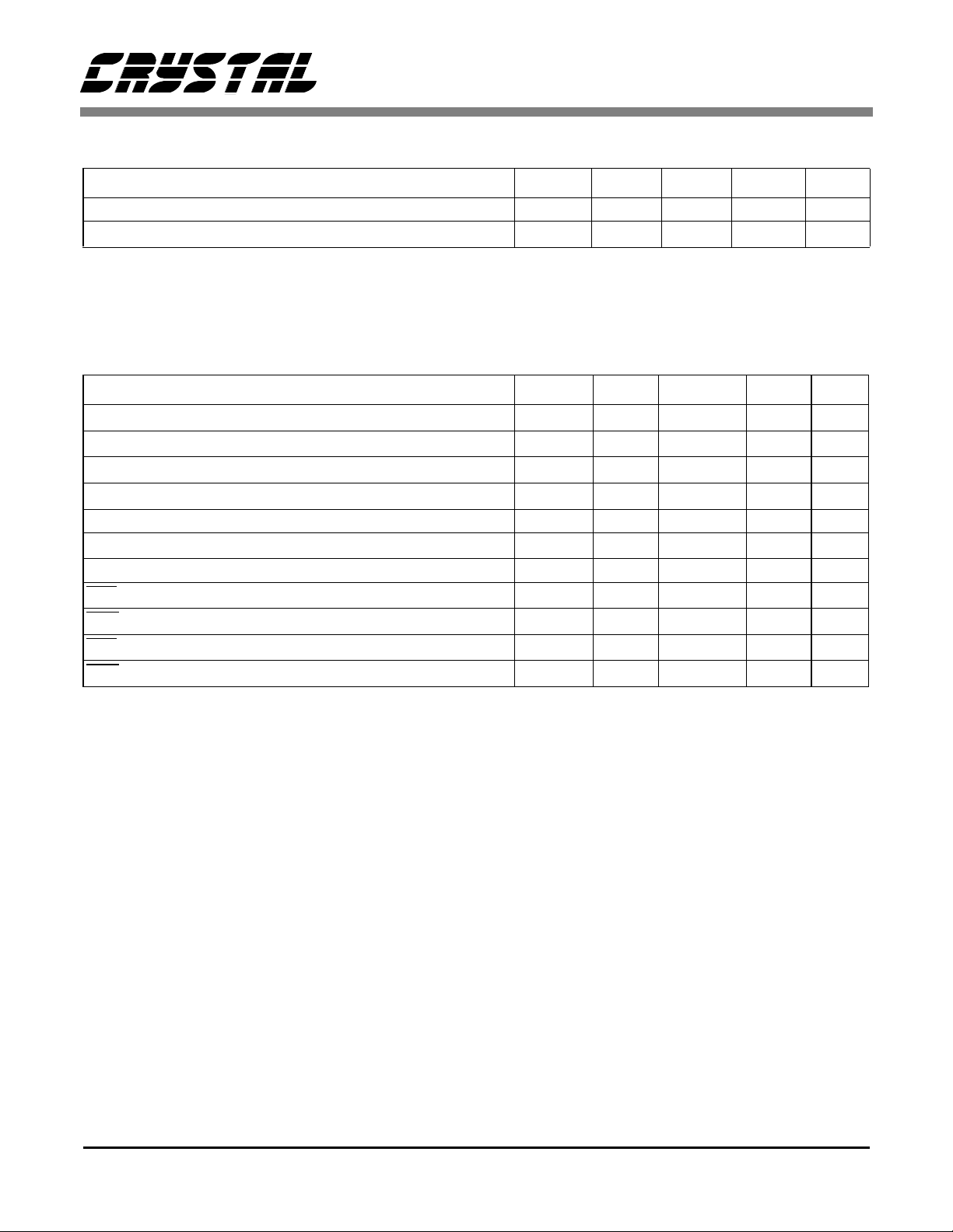
RECOMMENDED OPERATING CONDITIONS (DGND=0V, all voltages with respect to 0V.)
Parameter Symbol Min Typ Max Units
Power Supply VD 3.0 3.3 3.6 V
Operating Ambient Temperature
Per JEDEC Standard No. 8-A for LVCMOS
T
A
02570°C
SWITCHING CHARACTERISTICS (T
= 0 - 70 °C; VD = +3.3V ± .3V, outputs loaded with 30pF;
A
Input Levels: Logic 0 = 0V, Logic 1 = 5V) (Not e 1)
Parameter Symbol Min Typ Max Units
t
t
f
f
ck
ckl
ckh
lrw
16.92 16.9344 16.95 MHz
23.6 - - ns
23.6 - - ns
-44.1-kHz
Input clock (CLKIN) frequency (Note 2)
CLKIN low time
CLKIN high time
LRCLK frequency (Note 2)
LRCLK duty cycle 47 50 53 %
SOUT delay from LRCLK rising/falling edge
t
sdsk
--10ns
MIDI_IN Bit Rate (Asynchronous to MCLK5I or XTAL3I) 30937.5 31250 31562.5 bits/s
RST
pulse width low
PDN
pulse width low
high to valid MIDI input
RST
PDN
high to valid MIDI input
t
rpw
t
ppw
t
t
rdr
rdp
500 - - ns
500 - - ns
300 - - ms
0.15 - - ms
Notes: 1. XTAL3I input level is VD.
2. LRCLK frequency is equal to f
achieved when CLKIN frequency, f
/384. Optimum synthesized pitch and envelope characteristics will be
ck
, is equal to 16.9344 MHz (LRCLK frequency, f
ck
= 44.1 kHz).
lrw
Specification s are subject to change without notice.
4 DS214PP11
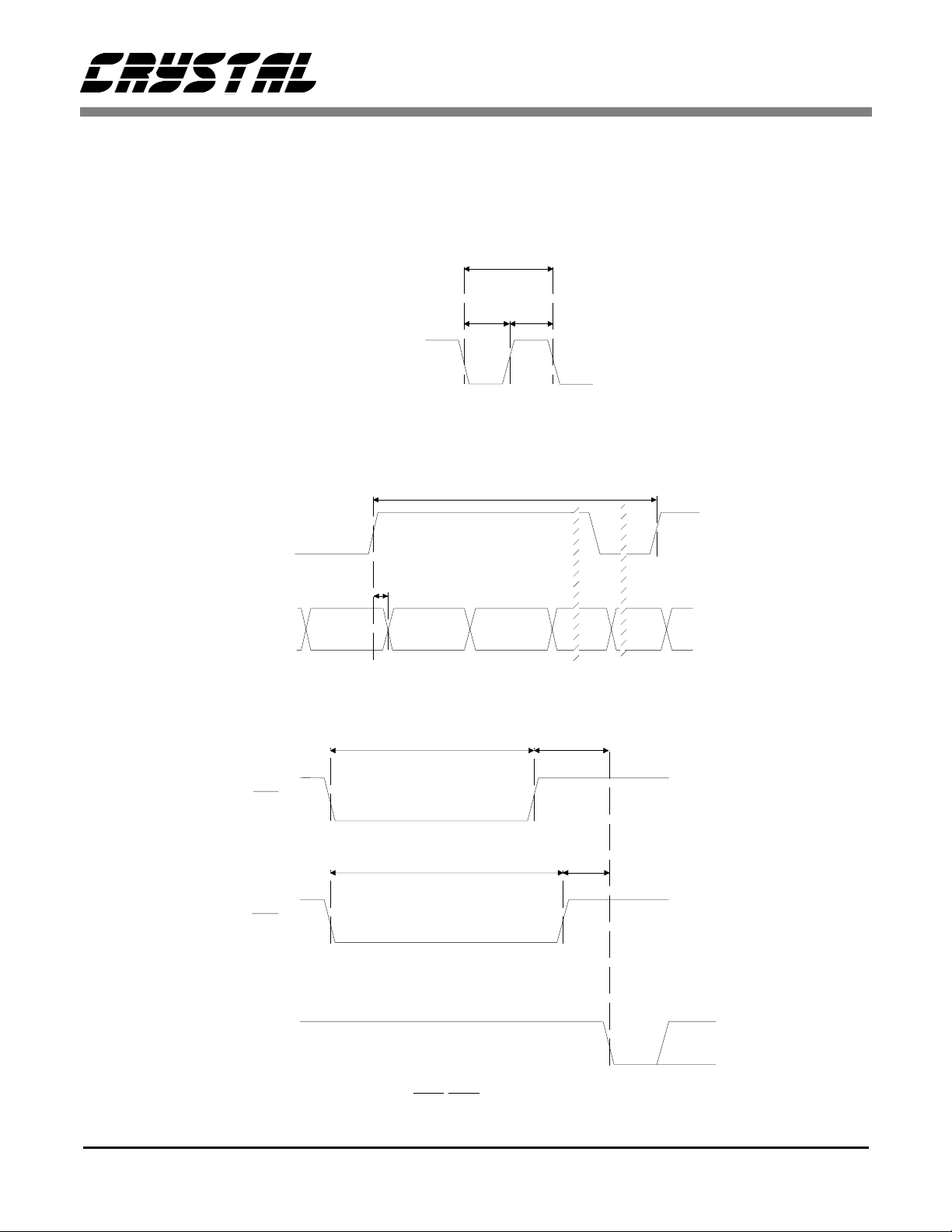
MCLK_IN
Master Clock Timing
-1
(f )
ck
t
ckltckh
-1
(f )
lrw
CS9236
LRCLK
SOUT
RST
PDN
t
sdsk
Digital Audio Port Timing
t
rpw
t
ppw
t
rdr
t
rdp
MIDI_IN
Start Bit
MIDI
DATA
RST/PDN Timing
DS214PP11 5
CS9236
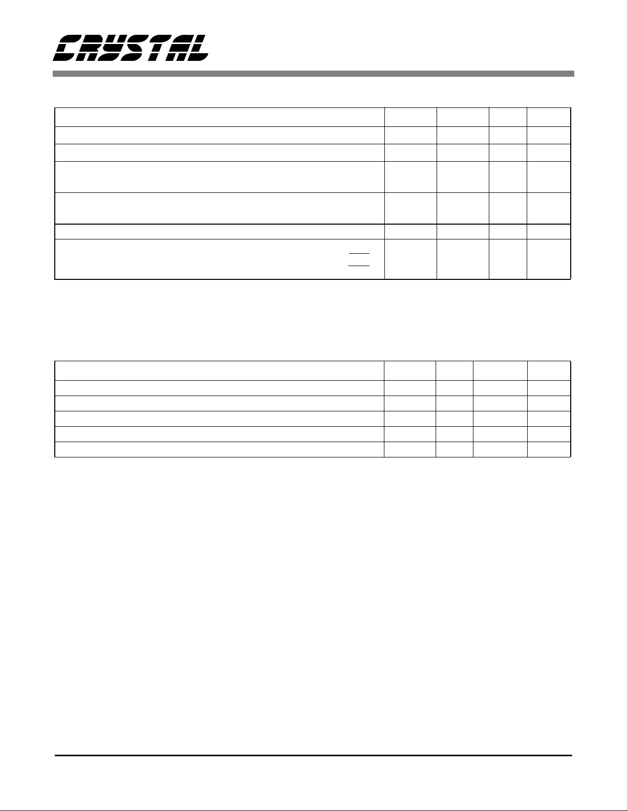
DIGITAL CHARACTERISTICS (T
= 25 °C; VD = +3.3V)
A
Parameter Symbol Min Max Units
High-level Input Voltag e (Note 3)
Low-level Input Voltage
High-level Output Voltage at I
= -100µA
O
at IO = -1mA
Low-level Output Voltage at I
= 100µA
O
at IO = 4mA
V
IH
V
IL
V
OH
V
OL
Input leakage Current (Digital Inputs) - 10
Supply Current (Normal Operation)
(Power Down with RST
)
(Power Down with PDN)
2.0 - V
-0.3 0.8 V
VD - 0.3
VD - 0.5
-
-
-
-
-
-V
0.3
0.5
150
400
1
V
µ
mA
µ
mA
A
A
Notes: 3. JEDEC Standard No. 8-A for LVCMOS, copyright Electronic Industries Association 1994, specifies
VD+0.3 max. CS9236 digital inputs are +5V tolerant.
ABSOLUTE MAXIMUM RATINGS (DGND = 0V, all voltages with respect to 0V)
Parameter Symbol Min Max Units
Power Supplies VD -0.3 4.6 V
Input Current (Except Supply Pins) - ±20 mA
Digital Input Voltage -0.3 5.25 V
Ambient Temperature (Power Applied) -55 125 ° C
Storage Temperature -55 125 ° C
Warning: Operation beyond these limits may result in permanent damage to the device.
Normal operation is not guar anteed at these extremes.
6 DS214PP11
CS9236
GENERAL DESCRIPTION
The CS9236 is a complete 32-note General MIDI music synthesizer with integra l di git al effects processing in a s ing le device. This device accepts a standard serial MIDI data stream
at 31.25 kbit /s and ge nerat es a s tereo digi tal a udio o utput data
stream at 44.1 ksample/s sampling rate. The device operates
from a sing le 3.3VDC s upply. Th e digi tal i nputs to the de vice
are 5V toler ant , allowing dir ect co nne ction to part s wh ich are
powered from 5V or 3V supplies. The CS9236 has been designed to interface directly with the Crystal Semiconductor
CS4236B/37B/38B Single Chip Audio Systems and with the
CS4333 Stereo D/A Converter (DAC). When the CS9236 is
used in conjunction with the CS4236B/37B/38B, the digital
audio output from the CS9236 is input to the CS4236B/37B/
38B in digital format, so no separate DAC is required. In applications which require an analog output from the CS9236,
the CS4333 DAC is employed to convert the digital audio
output of the CS9236 into analog format.
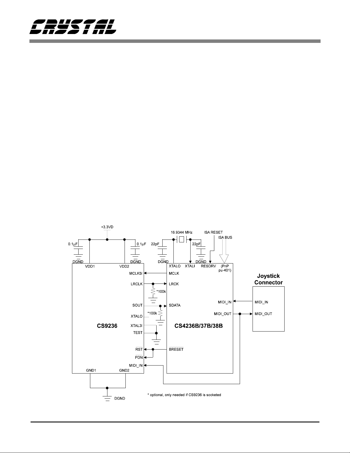
CS9236/CS4236B/ 37B/38B Ty pical Connecti ons
The CS9236 combine d wi th t he CS4236B/37B/38B prov id es
a complete ISA Plug-and-Play compatible sound system for
multimedia PC ap pli ca ti ons . Fi gur e 1 depicts the typ ic al con nections between the CS9236 and the CS4236B/37B/38B. In
this application, the CS4236B/37B/38B 16.9344 MHz
MCLK gated clo ck out put d rives the CS9236 MC LK5I inpu t,
eliminating the need for a separate quartz cryst al circuit.
MIDI messages are sent from the host PC to the CS4237B
over the ISA bus. The CS4236B/37B/38B provides a Plugand-Play configurable MPU-401 UART mode-compatible
ISA MIDI interface. The CS4236B/37B/38B MPU-401
UART function transmits the MIDI data received over the
ISA bus to the CS9236 (and to the Joystick MIDI Out pin) in
serial format. The CS9236 interprets the MIDI messages and
generates the appropriate musical sounds. These sounds are
output in seri al digital audi o format at the CS9236 SOUT pin.
The digital audio output from the CS9236 is input directly
into the CS4236B/37B/38B, eliminating the need for a separate DAC.
For more details on using the CS9236 with the CS4236B/
37B/38B, see Application Note 92, "Configuring the
CS423xB/CS9236 Wavetable Interface."
Figure 1. CS9236/CS4236B, CS4237B or CS4238B Typical Connections
DS214PP11 7
CS9236
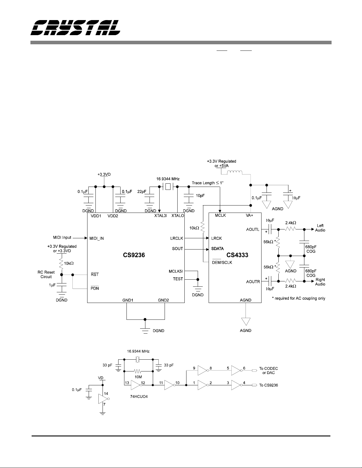
CS9236/CS4333 Typical C onnections
In applications which require analog audio output from the
CS9236 synthesizer, the CS4333 Stereo DAC is utilized.
Figure 2 shows typical connections for a stand-alone music
synthesizer application (e.g. low-cost musical keyboards,
MIDI modules, game boxes). In this application the CS9236
digital audio output, SOUT, and the associated clocks, LRCLK and XTALO, are input to the CS4333. The CS4333
converts t he stereo di gital au dio data st ream int o left and r ight
analog audio outputs, LOUT and ROUT.
Note that the e xampl e s hown i n Fi gur e 2 e mploy s an R-C filter circuit to generate a reset signal which is applied to both
the CS9236 RST
may be desirable to control one or both of these control signals dynamically.
The CS4333 clock input is driven by the CS9236 crystal oscillator output pin. The CS9236 must be placed as close as
possible to the CS4333 in order to mini miz e th e le ngth of the
XTALO/MCLK trace. The XTALO capacitor must be 10 pF,
while the XTAL3I capacitor remains the typical 22 pF. If the
CS9236 cannot be placed close to the CS4333, the buffered
crystal circuit shown in Figure 3 or a MicroClock MK144402 clock gener ator may be used. Do n ot use separ ate 16.93 44
MHz crystals/clock sources for the synthesizer and DAC.
and PDN inputs. In some applications it
Figure 2. CS9236/CS4333 Typical Connections.
Figure 3. Buffered Crystal Oscillator Circuit.
8 DS214PP11

CS9236
CS9236 Clocks and T iming Generation
The CS9236 internal timing is derived from one of two possible sources; the part may be supplied a 16.9344 MHz Master Clock signal from an exte rnal sour ce, or the ti ming may be
generated using the on-chip oscillator circuit in conjunction
with an external 16.9344 MHz quar t z cr ys tal . When a Master
Clock signal is provided to the CS9236 from an external device, the Master Clock signal should be connected to the
CS9236 MCLK5I input pin and the XTAL3I input pin is
grounded. W he n t he CS9236 internal ti min g i s generated us ing the on- chi p o sci l lat or circuit, a 16.9344 MHz quar tz crystal is connected between the CS9236 XTAL3I input pin and
the XTALO output p in, and t he MCLK5I i nput p in is groun ded. In this case, the XTALO output may also be used as a
384X master clock fo r the CS9 236 digit al audi o output signal,
SOUT.
Power-Down Modes
The CS9236 provides a fully-static power-down mode of operation. The power-down mode is i nitiated either by asserti on
of the active-low PDN
input signal (vi a the CODEC DMCLK bit in CS4236B/7B/8B
applications). In the power-down mode of operation, clock
signals t o virt ually al l of th e CS9236 interna l circu itry ar e gated off to minimize power consumption. The CS9236 device
is fully static, so all internal states and register values will be
retained during power-down, provided that power remains
applied to the d evice a nd that the RST
tive. Power-down operation is terminated either by deassertion of P DN
or by gating back on the MCLK5I input signal.
The device will then resume normal operation.
signal, or by ga ting off of the MCLK5I
signal re mains in ac-
Digital Audio Interfa ce
The CS9236 provides a stereo 16-bit serial digital audio output at a 44 .1 ksampl e/s s ampling rate. The CS9236 digit al au dio output is compatible with the Crystal Semiconductor
CS4236B/37B/38B and CS4333 devices. The digital audio
interface consists of the digital audio output signal, SOUT,
and the associated left/right word clock output, LRCLK.
Transitions of the SOUT and LRCLK signals are synchronous to the CS9236 crystal oscillator output clock, XTALO.
The relationship between the CS9236 SOUT data output and
the LRCLK clock output is indicated in Figure 4.
Reset
The CS9236 is initial ized/ rese t to a known defa ult st ate usi ng
the RST
on time to initialize th e part. Min imum RST
500 ns.
signal. The RST signal should be applied at power-
pulse width is
15
Left Channel
13 12111098765432114 0 15 1312111098765432114 00
LRCLK
SOUT 8-bits 8-bits
Right Channel
Figure 4. Digital Audio Port Format.
DS214PP11 9

CS9236
GENERAL MIDI (GM) MELODIC
INSTRUMENTS AND PERCUSSION
SOUNDS
The CS9236 supports 128 melodic instruments and 47 percussive sounds as specified by the General MIDI Level 1
specification.
MIDI messages generally consist of a single status byte followed by one or two data bytes (Real-Time messages and
System Exclusive messages are exceptions). The status byte
is an eight-bit value whic h i ndi cat es the type of messa ge, a n d
for Channel Voice or Channel Mode messages, the MIDI
channel number to which the mes sa ge a ppl ie s. The most sig-
nificant bit of the Status byte is always a “1”. The most significant bit a MIDI Data byte is always a “0”, so a data byte
contains only 7 bits of useful data. Status bytes and Data
bytes for functions not implemented are ignored.
In General MIDI (GM) instruments like the CS9236, MIDI
channels 1 - 9 and 11 - 16 are used for melodic instruments.
On MIDI channels 1 - 9 and 11 - 16, the MIDI Program
Change messag e is used t o sel ec t the inst rument to be used on
a specific MIDI channel. The General MIDI melodic instrument set is listed in Table 1.
The General MIDI system reserves channel 10 for keymapped percussion sounds. The General MIDI percussion
map defines the asso ciati on of perc ussio n soun ds to ke y numbers (note numbers) for use on channel 10. Program Change
messages on channel 10 are ignored. The CS9236 includes
default settings for the PAN, the REVERB SEND level, and
the CHORUS SEND level for each of the General MIDI percussion sou nds. The PAN settin g used fo r a percus sion sound
on channel 10 is a function of both the CS9236 default value
and the MIDI PAN value for channel 10 (PAN messages on
channel 10 are interpreted by the CS9236 as relative, rather
than absol ute, v alues) . For ex ample, t he default pan value for
the Hand Clap is 54 (10 units left of center) and the default
pan value for the Tambourine is 74 (10 units right of center).
A MIDI PAN message on channel 10 indicating a new pan
value of 50 (14 units left of center) for the channel would
place the Hand Clap at 40 (24 units left of center), and the
Tambourine at 60 (4 units left of center). A MIDI PAN message on channel 10 indicating a new pan value of 0 (64 units
left of center, or “hard left”) for the channel would place the
Hand Clap at 0 (hard l eft), a nd the Tambo urine at 10 (54 un its
left of center). The REVERB SEND level used for a percussion sound on channel 10 will be either the default value for
that percussion sound, or the MIDI REVERB SEND value
(MIDI Controller 91), whichever is greater. The CHORUS
SEND level used for a percussion sound on channel 10 will
be either the default value for that percussion sound, or the
MIDI CHORUS SEND value (MIDI Controller 93), whichever is greater.
Some of the pe rcussion instr umen t s ounds available on channel 10 belon g to “mutual ly exclu sive group s”. Althou gh multiple sounds may be generated simultaneously on channel 10
when operating in the normal POLY ON mode, no mo re th an
one sound from each of the mutually exclusive groups may
sound at a given time. For example, the Open Hi-Hat (Note
# 46), the Closed Hi-Hat (Note # 42), and the Pedal Hi-Hat
(Note # 44) all belong to the same mutually exclusive group.
If the Open Hi-Hat was already sounding when a MIDI
NOTE ON me ss age w as re c ei ved f o r th e Clo s ed H i-H at , the
Closed Hi-Hat woul d be played whi le the Open Hi -Hat would
be immediately forced into it’s release phase (the two notes
would overla p only for t he dura tion of th e releas e phase of t he
Open Hi-Hat sound). A Crash Cymbal sound (not a member
of this mutually exclusive group) which was also playing
when the NOTE ON message was received would not be affected.
The General MIDI percussi on sound map is giv en in Table 2.
This table also indicates the mutually exclusive group membership for each of the percussion sounds as implemented in
the CS9236.
10 DS214PP11

CS9236
PC# Instrument name PC# Instrument name PC# Instrument name PC# Instrument name
1 Acoustic Grand Piano
2 Bright Acoustic Piano
3 Electric Grand Piano
4 Honky-tonk Piano
5 Electric Piano 1
6 Electric Piano 2
7 Harpsichord
8Clavi
9 Celesta
10 Glockenspiel
11 Music Box
12 Vibraphone
13 Marimba
14 Xylophone
15 Tubular Bells
16 Dulc imer
17 Drawbar Organ
18 Percusive Organ
19 Rock Organ
20 Church Organ
21 Reed Organ
22 Accordion
23 Harmonica
24 Tango Accordian
25 Acoustic Guit. (nylon)
26 Ac oust ic G uit . (st eel )
27 Electric Guitar (jazz)
28 Electric Guitar (clean)
29 Electric Guitar (muted)
30 Overdriven Guitar
31 Distortion Guitar
32 Guitar harmonics
33 Acoustic Bass
34 Electric Bass (finger)
35 Electric Bass (pick)
36 Fretless Bass
37 Slap Bass 1
38 Slap Bass 2
39 Synth Bass 1
40 Synth Bass 2
41 Violin
42 Viola
43 Cello
44 Contrabass
45 Tremelo Strings
46 Pizzicato Strings
47 Orchestral Harp
48 Timpani
49 String Ensemble 1
50 String Ensemble 2
51 SynthStrings 1
52 SynthStrings 2
53 Choir Aahs
54 Voice Oohs
55 Synth Voice
56 Orchestra Hit
57 Trumpet
58 Trombone
59 Tuba
60 Muted Trumpet
61 French Horn
62 Brass Section
63 SynthBrass 1
64 SynthBrass 2
65 Soprano Sax
66 Alto Sax
67 Tenor Sax
68 Baritone Sax
69 Oboe
70 English Horn
71 Bassoon
72 Clarinet
73 Picclo
74 Flute
75 Recorder
76 Pan Flute
77 Blown Bottle
78 Shakuhachi
79 Whistle
80 Ocarina
81 Lead 1 (square)
82 Lead 2 (sawtooth)
83 Lead 3 (calliope)
84 Lead 4 (chiff)
85 Lead 5 (charang)
86 Lead 6 (voice)
87 Lead 7 (fifths)
88 Lead 8 (bass + lead)
89 Pad 1 (new age)
90 Pad 2 (warm)
91 Pad 3 (polysynth)
92 Pad 4 (choir)
93 Pad 5 (bowed)
94 Pad 6 (metallic)
95 Pad 7 (halo)
96 Pad 8 (sweep)
97 FX 1 (rain)
98 FX 2 (soundtrack)
99 FX 3 (crystal)
100 FX 4 (atmosphere)
101 FX 5 (brightness)
102 FX 6 (goblins)
103 FX 7 (echoes)
104 FX 8 (sci-fi)
105 Sitar
106 Banjo
107 Shamisen
108 Koto
109 Kalimba
110 Bag Pipe
111 Fiddle
112 Shanai
113 Tinkle Bell
114 Agogo
115 Steel Drums
116 Woodblock
117 Taiko Drum
118 Melodic Tom
119 Synth Drum
120 Reverse Cymbal
121 Guitar Fret Noise
122 Breath Noise
123 Seashore
124 Bird Tweet
125 Telephone Ring
126 Helicopter
127 Applause
128 Gunshot
Table 1. General MIDI Melodic Instrument Map (MIDI channels 1 - 9, 11 - 16)
DS214PP11 11

CS9236
Note # Drum Sound Excl # Note # Drum Sound Excl #
35 Acoustic Bass Drum 59 Ride Cymbal 2
36 Bass Drum 1 60 Hi Bongo
37 Side Stick 61 Low Bongo
38 Acoustic Snare 62 Mute Hi Conga
39 Hand Clap 63 Open Hi Conga
40 Electric Snare 64 Low Conga
41 Low Floor Tom 65 High Timbale
42 Closed Hi-Hat 1 1 66 Low Timbale
43 High Floor Tom 67 High Agogo
44 Pedal Hi-Hat 1 1 68 Low Agogo
45 Low Tom 69 Cabasa
46 Open Hi-Hat 1 1 70 Maracas
47 Low Mid Tom 71 Short Whistle 2
48 Hi Mid Tom 72 Long Whistle 2
49 Crash Cymbal 1 73 Short Guiro 3
50 High Tom 74 Long Guiro 3
51 Ride Cymbal 1 75 Claves
52 Chinese Cymbal 76 Hi Wood Block
53 Ride Bell 77 Low Wood Block
54 Tambourine 78 Mute Cuica 4
55 Splash Cymbal 79 Open Cuica 4
56 Cowbell 80 Mute Triangle 5
57 Crash Cymbal 2 81 Open Triangle 5
58 Vibraslap
Table 2. General MIDI Percussion Map (MIDI channel 10 only)
12 DS214PP11

CS9236
MIDI IMPLEMENTATION
The CS9236 MIDI int erpre te r respo nds to al l MIDI m essag es
specified for General MIDI Level 1.0 compliance. The GM
messages include NOTE ON, NOTE OFF, PROGRAM
CHANGE, CHANNEL PRESSURE, PITCH BEND
CHANGE, MODULATION WHEEL (Controller 1), DATA
ENTRY (Controller s 6 & 18) , VOLUME (Contro ller 7), PAN
(Controller 10), EXPRESSION (Controller 11), DAMPER
PEDAL/SUSTAIN (Controller 64), PITCH BEND SENSITIVITY (RPN 00), FINE TUNING (RPN 01), COARSE
TUNING (RPN 02), RESET ALL CONTROLLERS, and
ALL NOTES OFF.
In addition, the CS9236 MIDI interpreter responds to SOSTENUTO (Controller 66), EFFECT 1/REVERB SEND
LEVEL (Controller 91), EFFECT 3/CHORUS SEND LEVEL (Controller 93), ALL SOUNDS OFF, OMNI MODE OFF
(treated as ALL NOTES OFF), OMNI MODE ON (treated as
ALL NOTES OFF), MONO MODE ON, POLY MODE ON,
ACTIVE SENSING, SYSTEM RESET, and System Exclusive messages (System Exclusive messages may be used to
enable/di sable cha nnel press ure and to enable /disabl e inte rnal
test mode).
The MIDI inte rpret er c orrec tly i nterp rets MID I data str eams
transmitted usin g Running St atus. “Run ning Sta tus” i s appli cable to Channel Voic e messages and to Channel Mode Messages as follows: when a group of sequential messages in a
MIDI data s trea m shoul d have the sa me sta tus by te va lue, t he
status byte must be included for the first message in the
group, but may be omi tted for t he su bseq uent me ssages of t he
same status byte value. Running status allows long strings of
Channel Voice or Channel Mode messages to be sent using
only data bytes, wit h the stat us by te i nferr ed by t he la st Channel Voice or Channel Mode status byte received. A message
with a diffe rent st atus by te va lue wil l rese t th e runnin g statu s.
Note that even messages which are “ignored” or not otherwise processed by the CS9236 will reset the running status
mode. Real-Time messages are an exception to this rule:
Real-Time messages do not affect running status.
A MIDI Impleme ntati on Char t for the CS9 236 is given i n Table 3.
Channel Voice Messages
Channel Voice messages are used to control instrument voices. Channel Voice messages consist of a status byte followed
by one or two data bytes. Channel Voice messa ges which are
processed by t he CS9236 inc lude the NOTE ON, NOTE OFF,
CONTROL CHANGE, PROGRAM CHANGE, PITCH
BEND CHANGE, and CHANNEL PRESSURE messages.
Control Change Messages
The CS9236 processes MIDI Contr ol ler number s 1 (MODULATION WHEEL), 6 (DATA ENTRY MSB), 7 (CHANNEL VOLUME), 10 (PAN), 11 (EXPRESSION), 38 (DATA
ENTRY LSB), 64 (DAMPER PEDAL), 66 (SOSTENUTO),
91 (REVERB DEPTH), 93 (CHORUS DEPTH), 100 (Regis ter Parameter LSB), 101 (Register Parameter MSB), 120
(ALL SOUNDS OFF), and 121 (RESET ALL CONTROLLERS).
Registered Parameters
MIDI “Registered Parameter” data is transmitted to the
CS9236 using controller numbers 100 (Regis te re d Parameter
LSB), 101 (Registered Parameter MSB), 6 (Data Entry
MSB), and 38 (Data Entry LSB). To transfer parameter data
to the CS9236, the parameter number for the parameter to be
updated is first select ed using MIDI Cont rolle rs 100 and 101,
and then the data valu e for the se lect ed param eter is trans mitted using cont rol le r n umber s 6 a nd 38. The CS9236 respon ds
to the MIDI Registered Parameters for PITCH BEND SENSITIVITY (RPN00), FINE TUNING (RPN01), and
COARSE TUNING (RPN02).
Channel Mode Messages
The CS9236, like other popular synthesizer products, operates in a mode sometimes referred to as “Multimode”, described as follows:
The CS9236 MIDI c ontrol ler consi sts of 16 r eceive r ch annel s
(one receiver channel for each of the 16 MIDI channels).
Each receiver channel receives MIDI messages on it's dedicated MIDI channel. Each receiver channel can also receive
MODE messages on it's dedicated MIDI channel (the MIDI
channel for each receiver is also the “basic channel” for that
receiver) as follows: Each receiver channel is considered to
operate onl y i n O MNI OFF mode, (e ach receiver c hannel can
only receive data on one MIDI channel). When a receiver
channel receives an OMNI ON message, it stops all ongoing
notes but remains in OMNI OFF mode.
Each receiver channel can accept a POLY ON message or a
MONO ON message. The POLY ON message sets the receiv-
DS214PP11 13

er channel to “ Mo de 3” ope rat i on (OMNI OFF/POLY). This
is the default mode of operation for all receiver channels. In
mode 3, the receiver channel responds to MIDI messages on
it's dedicated MIDI channel polyphonically (it can play multiple MI DI notes simultaneously).
The MONO ON message sets the receiver channel to “Mode
4” operation (OMNI OFF/MONO). In mode 4, the receiver
channel responds to MIDI messages on it's dedicated MIDI
channel monoph oni cal ly (it can only pl ay one M IDI not e at a
time). In this mode , if a NO TE ON m essage is recei ved on
the receive r's MIDI ch anne l while a not e is alrea dy soundi ng,
the receiv er will quick ly turn off the note which is alr eady
sounding and play the new note.
System Realtime Messages
MIDI SYSTEM REAL TIME messages may occur at any
point in the MIDI data stream, including between the Status
and Data bytes of another MIDI message. SYSTEM REAL
TIME messages are not interpreted as a new receiver status
and do not af fe ct th e operation of Ru nni ng St at us. The MIDI
SYSTEM REAL TIME messages are: TIMING CLOCK
(F8H), START (FAH), CONTINUE (FBH), STOP (FCH),
ACTIVE SENSING (FEH), and SYSTEM RESET (FFH).
The CS9236 processes the ACTIVE SENSING and SYSTEM RESET messages only. The TIMING CLOCK,
START, CONTINUE and STOP messages are ignored.
CS9236
System Exclusive Messages
The CS9236 supports MIDI System Exclusive Messages for
enabling/disabling receipt of MIDI Channel Pressure and for
enabling/disabling of the CS9236 test tone. The System Exclusive Manufa ct urer ID assigned for Crys tal Semic onductor
Corporation is 0x00, 0x01, 0x02. The Product ID for the
CS9236 is 0x01, and the Version Number is 0x01.
The CS9236 will power-up with Channel Pressure disabled.
To enable Channel Pressure, the ENABLE RECOGNITION
OF MIDI CHANNEL PRESSURE System Exclusive message must be sent. Channel Pressure is disabled by sending
the DISABLE RECOGNITION OF MIDI CHANNEL
PRESSURE message. Likewise, for testing purposes, a feature to enable a test tone is available. To begin playing the
test tone, the ENABLE TEST TONE System Exclusi ve message must be sent. To turn the tone off, the DISABLE TEST
TONE message must be sent.
14 DS214PP11

CS9236
WAVETABLE SYNTHESIZER Date: July 11, 1996
Model: CS9236
Function Transmitted Recognized Remarks
Basic
Channel
Mode Default
Note
Number True Voice
Velocity Note On
After
Touch
Pitch Bend XO
Control
Change
Program
Change True Number
System Exclusiv e XO
System
Common
System
Real Time
Aux
Messages
Default
Changed
Messages
Altered
Note Off
Key’s
Channel
6, 38
100, 101
Song Position
Song Select
Tune Request
Clock
Commands
All Sounds Off
Reset All Controllers
Local O n/Of f
All Notes Off
Active Sensing
System Reset
Poly On
Mono On
X
X
X
X
********* ***
X
********* ***
X
X
X
X
1
X
X
7
X
10
X
11
X
64
X
66
X
91
X
93
X
X
X
********* ***
X
X
X
X
X
X
X
X
X
X
X
X
X
Notes 1. For Mode selection, this device respond s as 16 MIDI receivers, one for each MIDI channel. Each MIDI
receiver accept s mode messages on it’s own MIDI channel (basi c channel = MIDI channel o f receiver).
Each MIDI receiver operates in MODE 3 (default) or MODE 4 only.
MODE 1: Omni On, Ploly MODE 2: Omni On, Mono 0: Yes
MODE 3: Omni Off, Poly MODE 4: Omni Off, Mono X: No
MIDI Implementation Chart Version: 1.00
1 - 16
X
Mode 3
OMNI OFF, POLY, MONO (m=1)
OMNI ON > OMNI OFF
0 - 127
0 - 127
O
X
X
O
O
O
O
O
O
O
O
O
O
O
O
0 - 127 Program Numbers 1 - 128
X
X
X
X
X
O
O
X
O
O
O
O
O
"Multi-mode operation", Note 1.
Channels 1 - 16, Note 1.
Note 1
Note 1
Modulation Wheel
Data Entry MSB, LSB
Channel Volume
Pan
Expression
Damper Pedal (Sustain)
Sostenuto
Effect 1 Depth (Reverb)
Effect 3 Depth (Chorus)
RPN LSB, MSB
Table 3. MIDI Implementation Chart
DS214PP11 15

CS9236
Message Definitions
Channel Voice Messages
NOTE ON
9nH kkH vvH
n = MIDI channel number 0 - FH (1 - 16)
kk = note number 00 - 7FH (0 - 127)
vv = velocity 00 - 7FH (1 - 127)
The NOTE ON message is used to turn on a note for a specified MIDI channel. Note number 3CH (60) is Middle C. In the
CS9236, the NOTE ON velocity value may contr ol se ver al characterist ic s of t he r esulting sound. The ve locity value is used
to scale the amplitude envelope for all of the instruments in the CS9236 according to the following formula:
Max_env = (constant) * 10 ^ ((127 - velocity_value) * (-0.00835)).
For certain instruments, the velocity value also affects characteristics such as low-pass filter cutoff frequency, allowing the
timbre o f t h e i nstr u me nt to cha n g e su bt le ty a s a f unc ti on of ve lo ci ty. M ID I co n tr oll er s/ tr an sm it ters w hic h ar e not ve lo cit y
sensitive should use velocity = 40H (64). A NOTE ON message with velocity = 00 is defined to be a NOTE OFF message
with NOTE OFF velocity of 40H (this all ows long st rings of NOTE ON and NOTE OFF events to be sent as da ta bytes only
using running status).
NOTE OFF
8nH kkH vvH
or
9nH kkH 00H
n = MIDI channel number 0 - FH (1 - 16)
kk = note number 00 - 7FH (0 - 127)
vv = velocity 00 - 7FH (ignored)
The NOTE OFF message is used to turn off a note on a specified MIDI channel (this message triggers the “release” portion
of the note’s amplitude envelope, wherein the amplitude decays to zero). Note number 3CH (60) = Middle C. MIDI controllers/transmitters which are not velocity sensitive should use velocity = 40H. The NOTE OFF velocity value is ignored
by the CS9236. A note c an be t urned off us ing t he NOTE OFF mes sage ( stat us byt e = 8nH) or usin g the NOTE ON mess age
(9nH) with velocity = 00. The NOTE ON message with velocity = 00 is defined to be a NOTE OFF message with NOTE
OFF velocity of 40H (this all ows long strings of NOTE ON and NOTE OFF events to be sent as data bytes only using running
status). The DAMPER PEDAL (Sustain) ON (MIDI Controller 64) takes priority over the NOTE OFF and ALL NOTES
OFF messages: the NO TE OFF or ALL NOTES OFF messa ges are reco gnized , but not act ed on until t he DAMPER PEDAL
is released (OFF). The SOSTENUTO PEDAL (MIDI Controller 66) ON takes priority over the NOTE OFF and ALL
NOTES OFF messages in a s imilar way, wit h the exc eptio n that SOSTEN UTO only af fects notes w hich wer e alre ady acti ve
at the time that SOSTENUTO was switched from OFF to ON (See description of DAMPER PEDAL and SOSTENUTO messages).
16 DS214PP11

CS9236
Channel Voic e Messages (Con tinued)
PROGRAM CHANGE
CnH ppH
n = MIDI channel number 0 - FH (1 - 16)
pp = program number 00 - 7FH (1 - 128)
For the “melodic instrument channels” (MIDI channels 1 - 9, 11 - 16), the PROGRAM CHANGE message is used to select
the melodic instrument to be used on a specified MIDI channel. MIDI channel 10 is used for the General MIDI percussion
set, and PROGRAM CHANGE messages on MIDI channel 10 are ignored.
In this document, the melodic instruments are numbered from 1 through 127 (MIDI program number value +1). The Program Change mes sa ge does not affe ct n otes in progr ess . Notes in Prog res s continue to s ound using their o ri ginal instru ment
selection. Note On messages received after the Program Change message will sound using the new instrument selection.
CHANNEL PRESSURE (Channel Aftertouch)
DnH vvH
n = MIDI channel number 0 - FH (1 - 16)
vv = value 00 - 7FH (0 - 127) <OFF>
In the CS9236, the MIDI Channel Pressure message may be used to control the pitch modulation (vibrato) level on a specified channel. Recognition of CHANNEL PRESSURE may be enabled or disabled in the CS9236 using MIDI System Exclusive messages. Recognition of CHANNEL PRESSURE is disabled by default (CHANNEL PRESSURE messages are
ignored). When recognition of CHANNEL PRESSURE is enabled, the CHANNEL PRESSURE value is summed with the
current MODULATION WHEEL value and with the default modulation level defined for the selected instrument on the
specified channel to determine the actual vibrato level applied to the sound. When enabled, CHANNEL PRESSURE at
maximum value will contribute a modulation (vibrato) depth of 50 cents. The response curve is linear. The total depth, resulting from CHANNEL PRESSURE, MODULATION WHEEL, and de fault modula tion le vel, ma y be as high a s one semitone. When enabled, CHANNEL PRESSURE affects all notes playing on the specified channel. Pitch modulation in the
CS9236 is implemented using independent low frequency oscillator (LFO) implementations for each note.
Some of the instruments implemented in the CS9236 include a default pitch envelope (the pitch of a note begins slightly
sharp or f lat, an d then r amps to the fin al pitc h for t he note) . For n otes wit h defaul t pitch envelope s, pitc h modula tion (v ibrato)
will begin only after the pitch envelope has reached final pitch.
DS214PP11 17

CS9236
Channel Voic e Messages (Con tinued)
PITCH BEND CH ANGE
EnH llH mmH
n = MIDI channel number 0 - FH (1 - 16)
mm,ll = value 00,00 - 40,00 - 7FH,7FH (-8192 - 0 - 8192)
The PITCH BEND CHANGE message is used to control a pitch offset from the values specifi ed in the NOTE ON messages
received on the specifie d ch annel. Th e PI TCH BEND CHANGE message app lies to all not es on th e speci fied channel . The
default value for P ITCH BEND CHANGE is zero. The pitch bend ra nge is set by t he PITCH BEND SENSIT IVITY message
(MIDI Controller 00). The default pitch bend range is +/- 2 semitones (a PITCH BEND CHANGE value of 8192 would
result in a pitch change of +2 semitones). The maximum pitch bend range is +/- 24 semitones (see PITCH BEND SENSITIVITY message description).
18 DS214PP11

CS9236
Control Change Messages
MODULATION WHEEL (CONTROLLER 1)
BnH 01H vvH
n = MIDI channel number 0 - FH (1 - 16)
vv = modulation depth 00 - 7FH (0 - 127)
In the CS9236, t he MODULATI ON WHEEL mess age (MIDI Controlle r 1 ) is used to control the pi t ch mod ulati on (v ibr at o)
level on a spec ified chann el. The MODULATION WHEEL dept h value is summed with t he current CHANNEL PRESSURE
value and with the default modulation level defined for the selected instrument on the specified channel to determine the
actual vibrato level applied to the sound. The MODULATION WHEEL at maximum depth value will contribute a modulation (vibrato) depth of 50 cents. The response curve is linear. The total depth, resulting from CHANNEL PRESSURE,
MODULATION WHEEL, and default modulation level, may be as high as one semitone. The MODULATION WHEEL
affects all notes playing on the specified channel. Pitch modulation in the CS9236 is implemented using independent low
frequency oscillator (LFO) implementations for each note.
Some of the instruments implemented in the CS9236 include a default pitch envelope (the pitch of a note begins slightly
sharp or f lat, an d then r amps to the fin al pitc h for t he note) . For n otes wit h defaul t pitch envelope s, pitc h modula tion (v ibrato)
will begin only after the pitch envelope has reached final pitch.
DATA ENTRY (CONT ROLLERS 6 and 38)
BnH 06H mmH
BnH 26H llH
n = MIDI channel number 0 - FH (1 - 16)
mm = data value MSB for specified RPN (see REGISTERED PARAMETER NUMBER description)
ll = data value LSB for specified RPN (see REGISTERED PARAMETER NUMBER description)
MIDI “Register ed Par amet er ” dat a is tr ans mitted to the CS9236 usi ng con tr oll er number s 100 (Registered Pa rame ter LSB),
101 (Registe red Par ameter MSB) , 6 (Da ta Entr y MSB), and 38 (Data En tr y LSB). To tr ansfe r para mete r data to the CS9 236,
the paramete r number for t he parameter to be updat ed is firs t sel ected using MIDI Con troller s 100 a nd 1 01, and t hen th e data
value for the selected parameter is transmitted using controller numbers 6 and 38. See description of REGISTERED PARAMETER NUMBER (Controllers 100 and 101).
VOLUME (CONTROL LER 7)
BnH 07H vvH
n = MIDI channel number 0 - FH (1 - 16)
vv = volume 00 - 7FH (0 - 127)
The VOLUME message (MIDI Controller 7) is used in conjunction with the MIDI EXPRESSION message (Controller 11)
to control t he over all volum e of notes on a s pecif ied M IDI ch annel. Th e VOLUM E and EXPRES SION c urv es ar e desc ribed
by the following equation:
Attenuation from full scale (dB) = 40 ln ((VOLUME_value * EXPRESSION_value) / (127^2))
The CS9236 default value for VOLUME is 100.
DS214PP11 19

CS9236
Control Change M essages (Con tinued)
PAN (CONTROLLER 10)
BnH 0AH vvH
n = MIDI channel number 0 - FH (1 - 16)
vv = pan 00 - 40 - 7FH (0 - 64 - 127) <Left - Center - Right>
The PAN message (MIDI Controller 10) is used to control the left/right output placement for notes played on the specified
MIDI channel. A PAN value of 0 indicates hard left, 64 indicates center (equally balanced between left and right), and 127
indicates hard right. The CS9236 implements an “equal-power” pan scaling as indicated by the following formulae:
Left_scaling = ((127 - PAN_value) / 127) ^ 0.5
Right_scaling = (PAN_value / 127) ^ 0.5
On the melodic instrument channels (MIDI channels 1 - 9, 11 - 16), the MIDI PAN value is absolute (the received value
replaces the default value for the instrument selected on the specified channel). On the percussion channel (MIDI channel
10) the MIDI PAN value is relative to the default value for each of the individual percussion sounds.
EXPRESSION (CONTROLLER 11)
BnH 0BH vvH
n = MIDI channel number 0 - FH (1 - 16)
vv = expression 00 - 7FH (0 - 127)
The VOLUME message (MIDI Controller 7) is used in conjunction with the MIDI EXPRESSION message (Controller 11)
to control t he over all volum e of notes on a s pecif ied M IDI ch annel. Th e VOLUM E and EXPRES SION c urv es ar e desc ribed
by the following equation:
Attenuation from full scale (dB) = 40 ln ((VOLUME_value * EXPRESSION_value) / (127^2))
The CS9236 default value for EXPRESSION is 127.
DAMPER PEDAL/SUSTAIN (CONTROLLER 64)
BnH 40H vvH
n = MIDI channel number 0 - FH (1 - 16)
vv = control value 00 - 3FH (0 - 63) <OFF>
40 - 7FH (64 - 127) <ON>
The DAMPER PEDAL (Controller 64) allows notes on a specified MIDI channel to continue sounding after their corresponding NOTE OFF messages have been received. The DAMPER PEDAL ON state takes priority over the NOTE OFF
and ALL NOTES OFF mes sag es: the NOTE OFF or ALL NOTES O FF mess ages are recogn iz ed, but not acted on until the
DAMPER PEDAL is set OFF (released). The DAMPER PEDAL ON state results in progression of the normal sustain envelope of ongoing notes.
20 DS214PP11

CS9236
Control Change M essages (Con tinued)
SOSTENUTO (CONTROLLER 66)
BnH 40H vvH
n = MIDI channel number 0 - FH (1 - 16)
vv = control value 00 - 3FH (0 - 63) <OFF>
40 - 7FH (64 - 127) <ON>
The effect of SOSTENUT O is simi lar to DAMPER PEDAL ( SUSTAIN), except that SOSTE NUTO only affects notes whi ch
were already active at the time that SOSTENUTO was switched ON. Notes which were already playing when the SOSTENUTO ON message is received will be sustained until the corresponding NOTE OFF message is received or until SOSTENUTO is turned OFF, whichever occurs later. NOTE ON messages which are received after SOSTENUTO has been
switched ON are not affected. The CS9236 default value for SOSTENUTO is zero (Off).
EFFECT 1 DEP TH/REVERB SE ND LEVEL (CON TROLLER 91)
BnH 5BH vvH
n = MIDI channel number 0 - FH (1 - 16)
vv = reverb send depth 00 - 7FH (0 - 127)
The REVERB SEND LEVEL message (MIDI Cont rol le r 9 1) i s us ed t o a dju st the amount of reverb ef fect applied to sounds
played on the sp ec if ied MIDI channel. Each mel odi c i nst rument (MIDI chan nel s 1 - 9, 11 - 16) and each individua l pe rcu ssion sound ( MIDI channel 10) i mplemented in the CS9236 has a predef i ned default rev er b send level. The reverb send lev el
used when a sound is produced is either the value received from a REVERB SEND LEVEL message (MIDI Controller 91)
or the defaul t for the melo dic i n st ru ment (or percussi on s ound) currentl y s el ect ed on the specif ied MIDI channel, whichever
is greater. The CS9236 reverb send level response curve is exponential.
EFFECT 3 DEPTH/ CHORUS SEND LEV EL (CONTROLLER 9 3)
BnH 5DH vvH
n = MIDI channel number 0 - FH (1 - 16)
vv = chorus send depth 00 - 7FH (0 - 127)
The CHORUS SEND LEVEL mes sag e (M IDI Co ntr ol le r 93) i s used to adju st t he amount of chor us ef fe ct applied to sou nds
played on the sp ec if ied MIDI channel. Each mel odi c i nst rument (MIDI chan nel s 1 - 9, 11 - 16) and each individua l pe rcu ssion sound (MIDI channel 10) impl emented i n the CS92 36 has a pr edefi ned default ch oru s send l evel. The chorus send lev el
used when a sound is produced is eit her the value rece iv ed fr om a CHORUS SEND LEVEL message (MIDI Contr ol le r 93)
or the defaul t for the melo dic instrument (or percussi on s oun d) currently s el ect ed on the spec ified MIDI channel, whichever
is greater. The CS9236 chorus send level response curve is exponential.
DS214PP11 21

CS9236
Control Change M essages (Con tinued)
REGISTERED PARAMETER N UMBER (RPN) (CONTROLLE RS 100 and 101)
BnH 65H mmH
BnH 64H llH
n = MIDI channel number 0 - FH (1 - 16)
mm = RPN parameter number (MSB)
ll = RPN parameter number (LSB)
MIDI “Register ed Par amet er ” dat a is tr ans mitted to the CS9236 usi ng con tr oll er number s 100 (Registered Pa rame ter LSB),
101 (Registe red Par ameter MSB) , 6 (Da ta Entr y MSB), and 38 (Data En tr y LSB). To tr ansfe r para mete r data to the CS9 236,
the paramete r number for t he parameter to be updat ed is firs t sel ected using MIDI Con troller s 100 a nd 1 01, and t hen th e data
value for t he s el ect ed parameter is transmi tt ed u sin g controller n umber s 6 and 38. The CS9236 rec ogni zes MIDI Reg is tered
Parameter Numbers 00 (PITCH BEND SENSITIVITY), 01 (FINE TUNING), and 02 (COURSE TUNING) as described in
the following paragraphs.
22 DS214PP11

CS9236
Registered Parameters
PITCH BEND SENSITIVITY (RPN 00)
RPN DATA
MSB LSB MSB LSB
00H 00H mmH llH
DESCRIPTION
PITCH BEND SENSITIVITY (RPN 00)
mm: sensitivity in semitones
Range is 00 - 18H (+/-0 to +/-24 semitones, default is +/-2 semitones)
ll: sensitivity in cents
Ignored
The PITCH BEND SENSITIVITY parameter (MIDI Registered Parameter Number 00) is used to set the amount of pitch
change which will result from subsequently received PITCH BEND CHANGE messages. The PITCH BEND SENSITIVITY is channel s pec ific (independe nt val ues are ma in tai ned for each MIDI channel). The CS9236 def aul t s ens it ivi t y is +/-2
semitones (a maximum value of PI TCH BEND CHANGE wi ll re sult in a pitch cha nge of +2 se mit ones, t he mini mum value
of PITCH BEND CHANGE will result in a pitch change of -2 semitones). The maximum sensitivity for the CS9236 is +/24 semitones ( +/- two oct ave s) . Se e description of REGIS TERED PARAMETER NUMBER (Co ntr ol le rs 100 an d 10 1) and
DATA ENTRY (Controllers 6 and 38) Control Change messages.
FINE TUNING (RPN 01)
RPN DATA
MSB LSB MSB LSB
00H 01H mmH llH
DESCRIPTION
FINE TUNING (RPN 01)
mm,ll: fine pitch offset in cents from A440
resolution is 100/8192 cents
range is 00,00 - 40,00 - 7FH,7FH
(-8192*100/8192 - 0 - +8191*100/8192 cent)
The FINE TUNING parameter (MIDI Registered Parameter Number 01) is used for fine tuning of the pitch of instruments
played on the specified MIDI channel. The FINE TUNING parameter provides high resolution control of tuning for pitch
changes of up to one semiton e. The COARSE TUNING parameter (MIDI Register ed Parameter Number 02) provi des coarse
tuning in semitone uni ts. See descrip tion of REGISTERED PARAMETER NUMBER (Contr ollers 100 and 101) and DATA
ENTRY (Controllers 6 and 38) Control Change messages.
DS214PP11 23

CS9236
Registered Parameters (Continued)
COARSE TUNING (RPN 02)
RPN DATA
MSB LSB MSB LSB
00H 02H mmH llH
DESCRIPTION
COARSE TUNING (RPN 02)
mm: pitch offset in semitones from A440
resolution is 100 cents (one semitone)
range is 28H - 40 - 58H (-24 - 0 - +24 semitone)
ll: ignored per MIDI spec
The COARSE TUNING parameter (MIDI Registered Parameter Number 02) is used for fine tuning of the pitch of instruments played on the specified MIDI channel. The COARSE TUNING parameter provides coarse tuning in semitone units.
The FINE TUNING parameter ( MIDI Regi stere d Parame ter Number 01) pr ovides high re solut ion con trol of t uning f or pit ch
changes of up to one semitone. See descript ion of REGISTERED PARAMETER NUMBER (Cont rol le rs 100 and 101 ) and
DATA ENTRY (Controllers 6 and 38) Control Change messages.
24 DS214PP11

CS9236
Channel Mode Message s
ALL SOUNDS OFF (Controller 120)
BnH 78H 00H
n = MIDI channel number 0 - FH (1 - 16)
The ALL SOUNDS OFF message is used to immediately turn off all sounds on the specified MIDI channel. Sounds which
are turned off using ALL SOUNDS OFF do not proceed through the normal release stage of their amplitude envelope(s).
RESET ALL CO NTROLLERS (Cont roller 121)
BnH 79H 00H
n = MIDI channel number 0 - FH (1 - 16)
The RESET ALL CONTROLLERS message is used to reset MIDI Controller values for the specified MIDI channel back
to their in itia l/def ault state s. The RESET A LL CONTR OLLERS me ssage will re stor e th e foll owin g paramet er val ues in t he
CS9236 (Note that r est or at ion of th e PI TCH BEND CHANGE value in response t o RESET ALL CONTROLLERS will not
affect notes already in progress):
Controller/MIDI parameter Value after RESET ALL CONTROLLERS
PITCH BEND CHANGE 40H, 40H (center)
CHANNEL PRESSURE 0H (Off)
MODULATION WHEEL 0H (Off)
EXPRESSION 7FH (127)
HOLD1 (Sustain) 0H (Off)
ALL NOTES OFF (Cont roller 123)
BnH 7BH 00H
n = MIDI channel number 0 - FH (1 - 16)
The ALL NOTES OFF message is used to turn of f all notes on the s pecif ied MID I chann el. No tes whi ch are turned off us ing
ALL NOTES OFF will proceed through the normal release stage of their amplitude envelope(s). The DAMPER PEDAL
(MIDI Controller 64) ON takes priority over the NOTE OFF and ALL NOTES OFF messages: the NOTE OFF or ALL
NOTES OFF messages are recognized, but not acted on until the DAMPER PEDAL is released (OFF). The SOSTENUTO
PEDAL (MIDI Controller 66 ) ON takes pri ority over the NOTE OFF and ALL NOTES OFF messa ges in a simila r way, with
the exception that SOSTENUTO only affects notes which were already active at the time that SOSTENUTO was switched
from OFF to ON (See description of DAMPER PEDAL and SOSTENUTO messages).
OMNI MODE OFF (Controller 124)
BnH 7CH 00H
n = MIDI channel number 0 - FH (1 - 16)
The CS9236 responds to the OMNI MODE OFF message as if it were an ALL NOTES OFF message (See ALL NOTES
OFF). The specified channel remains in OMNI OFF mode (All channels operate only in OMNI OFF mode in the CS9236).
DS214PP11 25

CS9236
Channel Mode M essages (Continue d)
OMNI MODE ON (Controller 125)
BnH 7DH 00H
n = MIDI channel number 0 - FH (1 - 16)
The CS9236 responds to the OMNI MODE ON message as if it were an ALL NOTES OFF message (See ALL NOTES
OFF). The specified channel remains in OMNI OFF mode (All channels operate only in OMNI OFF mode in the CS9236).
MONO MODE ON (Controller 126)
BnH 7EH mmH
n = MIDI channel number 0 - FH (1 - 16)
mm = number of mono 00 - 10H (0 - 16) <ignored>
On receipt of the MONO MODE ON message, the CS9236 performs ALL SOUNDS OFF on the specified MIDI channel
(see description o f ALL SOUNDS OFF messa ge), and t he speci fied chan nel is set to Mode 4 ( OMNI OFF/MONO). In mode
4, the specified channel will respond to MIDI messages monophonically (it can only play one MIDI note at a time). In this
mode, if a NOTE ON message is rece ived on the sp ecifi ed MIDI channel whil e a note is alre ady sound ing, the new note wil l
be played while the old/ongoing note is forced into the release phase of it’s amplitude envelope (the notes will overlap for
the duration of the release phase of the older note).
POLY MODE ON (Control ler 127)
BnH 7FH 00H
n = MIDI channel number 0 - FH (1 - 16)
On receipt of the POLY MODE ON message, the CS9236 performs ALL SOUNDS OFF on the specified MIDI channel
(see description of ALL SOUNDS OFF message), and the specified channel is set to Mode 3 (OMNI OFF/POLY). In
mode 3, the specified channel will respond to MIDI messages polyphonically (it can play multiple MIDI notes simultaneously). Mode 3 is the default mode of operation for each MIDI channel in the CS9236.
26 DS214PP11

CS9236
System Real Time Messages
ACTIVE SENSING
FEH
MIDI Transmitters wh ich are u sing active sensing will send t he ACTIVE SENSING message (FEH) ever y 300 ms maximum
(270 recommended) whenever there is no other MIDI data being transmitted. The CS9236 defaults to Active Sensing OFF
mode of operation. When the CS9236 detects an ACTIVE SENSING message, it begins operating in Active Sensing ON
mode. In Active Sensing ON mode, th e CS9236 monitors the elapsed ti me between recei pt of MIDI messag es. If the elapsed
time exceeds 372 ms., then the CS9236 executes ALL SOUNDS OFF and RESET ALL CONTROLLERS on each MIDI
channel and returns to Active Sensing OFF mode.
SYSTEM RESET
FFH
The SYSTEM RESET message wil l cause the CS92 36 to set Mode 3 (OMN I OFF/POLY) opera tion fo r each MIDI chann el,
execute ALL SOUNDS OFF and RESET ALL CONTROLLERS on each MIDI channel, return to Active Sensing OFF
mode, and return to initialized power-up status.
DS214PP11 27

CS9236
System Exclusive Messages
ENABLE RECOGNITION OF MIDI CHAN NEL PRESSURE
F0H 00H 01H 02H 01H 01H 01H F7H
F0H = MIDI System Exclusive Header
00H, 01H, 02H =
System Exclusive Manufact ur er ID:
Crystal Semiconductor Corp.
01H = Product ID: CS9236
01H = Model/Version ID: 01
01H = Message Type: Enable Channel Pressure
F7H = End of System Exclusive flag (EOX)
Receipt of the ENABLE RECOGNITION OF MIDI CHANNEL PRESSURE system exclusive message will cause the
CS9236 to recognize subsequent MIDI CHANNEL PRESSURE messages on all MIDI channels. (See description of
CHANNEL PRESSURE message). By default, the CS9236 disables recognition of CHANNEL PRESSURE.
DISABLE RECOGNITION OF MIDI CH ANNEL PRESSURE
F0H 00H 01H 02H 01H 01H 02H F7H
F0H = MIDI System Exclusive Header
00H, 01H, 02H =
System Exclusive Manufact ur er ID:
Crystal Semiconductor Corp.
01H = Product ID: CS9236
01H = Model/Version ID: 01
02H = Message Type: Disable Channel Pressure
F7H = End of System Exclusive flag (EOX)
Receipt of the DISABLE RECOGNITION OF MIDI CHANNEL PRESSURE system exclusive message will cause the
CS9236 to ignore subsequent MIDI CHANNEL PRESSURE messages on all MIDI channels. (See description of CHANNEL PRESSURE message). By default, the CS9236 disables recognition of CHANNEL PRESSURE.
28 DS214PP11

CS9236
System Exclusive Messages (Continued)
ENABLE TEST TONE
F0H 00H 01H 02H 01H 01H 03H F7H
F0H = MIDI System Exclusive Header
00H, 01H, 02H =
System Exclusive Manufact ur er ID:
Crystal Semiconductor Corp.
01H = Product ID: CS9236
01H = Model/Version ID: 01
03H = Message Type: Enable Test Mode
F7H = End of System Exclusive flag (EOX)
Receipt of the ENABLE TEST TONE system exclusive message will cause the CS9236 to output a 1 kHz sinusoidal test tone.
The test ton e output will be affe cted by M IDI Chan nel Voice Message s for MID I channel 1 0 (i.e. VOL UME, EX PRESSI ON,
PAN, PITCH BEND CHANGE, MODULATION, REVERB SEND LEVEL, CHORUS SEND LEVEL). The test tone output
level under default conditions for VOLUME, EXPRESSION, PAN, PITCH BEND CHANGE, MODULATION, REVERB
SEND LEVEL, and CHORUS SEND LEVEL on channel 10 is 34 dB below digital full scale. By default, the test tone output is
disabled.
DISABLE TEST TONE
F0H 00H 01H 02H 01H 01H 04H F7H
F0H = MIDI System Exclusive Header
00H, 01H, 02H =
System Exclusive Manufact ur er ID:
Crystal Semiconductor Corp.
01H = Product ID: CS9236
01H = Model/Version ID: 01
04H = Message Type: Disable Test Mode
F7H = End of System Exclusive flag (EOX)
Receipt of the DISABLE TE ST TONE system exclusive mes sage will cause the CS9236 to dis abl e t he t es t tone out put (See
description of ENABLE TEST TONE). By default, the test tone output is disabled.
DS214PP11 29

PIN DESCRIPTIONS
NC
NC
NC
NC
NC
NC
NC
MCLK5I
XTAL3I
XTAL0
GND2
VDD2
LRCLK
SOUT
NC
NC
NC
NC
NC
NC
NC
NC
NC
44
1
2
3
4
5
6
7
8
9
10
11
12 14 16 18 20 22
4042 343638
CS9236
44-pin TQFP
(Q)
33
32
31
30
29
28
27
26
25
24
23
CS9236
NC
NC
NC
NC
NC
NC
RST
PDN
GND1
VDD1
MIDI_IN
TEST
NC
NC
NC
NC
NC
NC
NC
NC
NC
NC
NC
NC
NC
MCLK5I
XTAL3I
XTAL0
GND2
VDD2
LRCLK
SOUT
NC
NC
NC
3272426281
5
6
7
8
9
10
11
CS9236
28-pin PLCC
(L)
12 14 16 1813 15 17
25
24
23
22
21
20
19
NC
NC
NC
NC
RST
PDN
GND1
VDD1
MIDI_IN
TEST
NC
NC
NC
NC
30 DS214PP11

MIDI_IN - Serial MIDI Data Input, PIN 20 (L), PIN 28 (Q).
Serial MIDI da ta input to the dev ice. This data stream contains MIDI messag es which are used
to control m usic sy nthesis an d initia tion/ter mination o f the Te st Tone.
SOUT - Serial Audio Data Output, PIN 11 (L), PIN 8 (Q).
Serial data output stream carrying the stereo digital audio output from the device. The digital
audio outpu t sample ra te is 44.1 ksamp le/s, stereo.
LRCLK - Serial Au dio Data Left/Ri ght Clock Output, PIN 10 ( L), PIN 7 (Q).
This is the left/right word clock output associated with the serial data output, SOUT. The
LRCLK signal identifies word alignment of the SOUT data stream.
RST
- Reset Input, PIN 24 (L), PIN 32 (Q).
This ac tive-low input signa l is used to in itializ e all o f the de vices i nternal state s and re gisters to
a known defau lt state. The RS T
- Power-Down Input, PIN 23 (L), PIN 31 (Q).
PDN
This active-low input signal is used to set the device to the low power consumption PowerDown mode of operat ion. The Power-Down mode is fully static; all interna l states and register
values are retained during Power-Down. Deassertion of the PDN
normal ope ration.
signal will si lence the dig ital audi o output.
signal returns the device to
CS9236
TEST - Factory Test Input, PIN 19 (L), PIN 27 (Q).
Used for factory testing of device. This pin must be tied to digital ground during normal
operation.
MCLK5I - 5 Volt Master Clock Input, PIN 5 (L) , PIN 2 (Q).
This is the m aster clock input for the device. The CS9236 inte rnal timing is derived from one
of two possib le sources; the part may b e supplied a 16.9344 M Hz Master Clo ck signal fro m an
external source, or the timing may be generated using the on-chip oscillator circuit in
conjunction with an external 16.9344 MHz quartz crystal. When a Master Clock signal is
provided to the CS9236 from an external device, the Master Clock signal should be conne cted
to the CS9236 MCLK5I input pin and the XTAL3I input pin is grounded. When the CS9236
internal tim ing is generated using th e on-chip oscillator circuit, a 16.9344 MHz quartz crystal is
connected between the CS9236 XTAL3I input pin and the XTALO output pin, and the
MCLK5I input pin is grounded. In this case, the XTALO output may also be used as a 384X
master clock for the CS9236 digital audio output signa l, SOUT.
DS214PP11 31

CS9236
XTAL3I - 3 Volt Crystal Oscill ator Input, PIN 6 (L), PIN 3 ( Q).
This is the input pin for the on-chip crystal oscillator circuit. The CS9236 internal timing is
derived from one of two possible sources; the part may be supplied a 16.9344 MHz Master
Clock signal from an external source, or the timing may be generated using the on-chip
oscillator circuit in conjunction with an external 16.9344 MHz quartz crystal. When a Master
Clock signal is provided to the CS9236 from an external device, the Master Clock signal
should be connec ted to the CS9236 MCL K5I input pin and the XT AL3I input pin is grounde d.
When the CS9236 internal timing is generated using the on-chip oscillator circuit, a 16.9344
MHz quartz crystal is connected between the CS9236 XTAL3I input pin and the XTALO
output pin, and the MCLK5I input pin is grounded. In this case, the XTALO output may be
used as a 384X master clock for the CS9236 digital audio ou tput signal, SOUT.
XTALO - Crystal Osci llator Output/38 4X Digital Audio Clock Output, PIN 7 (L ), PIN 4 (Q).
This pin is the out put of the on-chip crystal osc illator cir cuit. This output m ay also be used as a
384X master clock for the CS9236 digital audio output signal, SOUT. The CS9236 internal
timing is derived from one of two possible sources; the part may be supplied a 16.9344 MHz
Master Clock signal from an external source, or the timing may be generated usi ng the on-chip
oscillator circuit in conjunction with an external 16.9344 MHz quartz crystal. When a Master
Clock signal is provided to the CS9236 from an external device, the Master Clock signal
should be connec ted to the CS9236 MCL K5I input pin and the XT AL3I input pin is grounde d.
When the CS9236 internal timing is generated using the on-chip oscillator circuit, a 16.9344
MHz quartz crystal is connected between the CS9236 XTAL3I input pin and the XTALO
output pin, and the MCLK5I input pin is grounded. In this case, the XTALO output may be
used as a 384X master clock for the CS9236 digital audio ou tput signal, SOUT.
VDD1, VDD2 - Digital Supply Voltage, PINS 21 and 9 (L), PINS 29 and 6 (Q), respectively.
3.3VDC supply volt age connect ions for the devi ce.
GND1, GND2 - Digital Ground, PINS 22 and 8 (L), PINS 30 and 5 (Q), respectively.
0 VDC digital gro und connect ions for th e device.
NC - No Connection, PINS 1-4, 12-18 , 25-28 (L), PINS 1, 9-26, 33-44 (Q)
These pins must b e left floati ng (no connec tion to ext ernal circui try).
32 DS214PP11

PACKAGE PARAMETERS
D
D1
1
44 PIN TQFP
E1
CS9236
44 LEAD TQFP
MILLIMETERS
NOM
1.40
0.37
0.145
12.0
10.0
0.80
0.60
3.5°
MAX
1.60
0.15
1.45
0.45
0.20
12.25
10.10
0.90
0.75
7° 7°
0.10
MIN
DIM
A
A1
0.05
A2
1.35 0.053
b
E
0.09 0.004
c
D/E
11.75
D1/E1
9.90 0.390
e
0.70
L
0.45
0°
∝
ccc
INCHES
MIN MAX
NOM
0.063
0.002
0.014
0.462
0.026
0.018
0°
0.055
0.016
0.006
0.472
0.394
0.031
0.024
3.5°
0.006
0.057
0.0180.30
0.008
0.482
0.398
0.036
0.030
0.004
∝
c
L
e
b
MIN MAX
12.32
(0.485)
1.27(0.050)
x45deg.NOM
AB C
MIN MAX
12.57
11.43
(0.450)
11.58
(0.456 )
4.62 (0.182)
4.11 (0.162)
1.14 (0.045)
0.63 (0.025)
2.41 (0.095)
MIN
(0.495)
A2
A1
MIN MAX
9.91 10.92
(0.430)
(0.390)
0.25 (0.010) R
A
28 pin
PLCC
MAX
ccc
1.14 (0.045) x 45deg.
NOM
B
A
AB
C
1.35 (0.053)
1.19 (0.047)
3 NOM
3
0.46 ( 0.018 )
0.33 ( 0.013 )
NOM
ALL DIMENSIONS ARE IN MILLIMETERS AND PARENTHETICALLY IN INCHES.
DS214PP11 33

Smart
Analog
TM
is a Trademark of Crystal Semiconductor Corporation
 Loading...