

FEATURES
■ Single-Chip Quad IEEE 802.3-compliant Ethernet
Interface
■ 3 V and 5 V Operation
■ Full and Half Duplex Operation
■ Auto-Negotiation with Manual Override Capability
■ Four 10BASE-T Ports with Integrated Active Ana-
log Filters
■ Automatic Polarity Detection and Correction
■ Integrated Manchester Encoder/Decoders
(ENDEC)
■ Link Status LED Driver for Each Port
■ Per Port Control - Manual Duplex select (Half or
Full), Auto-Negotiation select, Loopback select
■ Per Port Status - Collision dete ct, Ca rr ie r det ec t,
Jabber indication, Link status, Duplex status,
Auto-Negotiation status
ORDERING INFORMATION
CS8904-CM5 0 to 70 °C 100-pin MQFP, 5.0 V
CS8904-CM3 0 to 70 °C 100-pin MQFP, 3.3 V
CDK8904-5 Developer’s Kit, 5.0 V
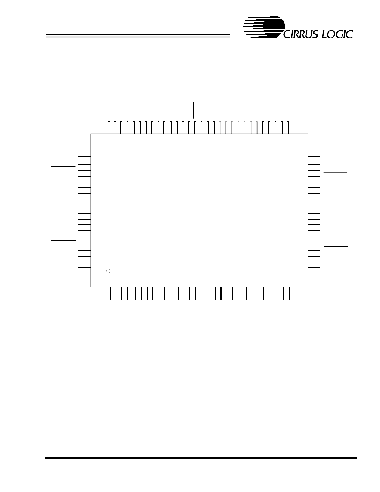
CS8904
Advanced Product Databook
Crystal LAN™ Quad
Ethernet Transceiver
DESCRIPTION
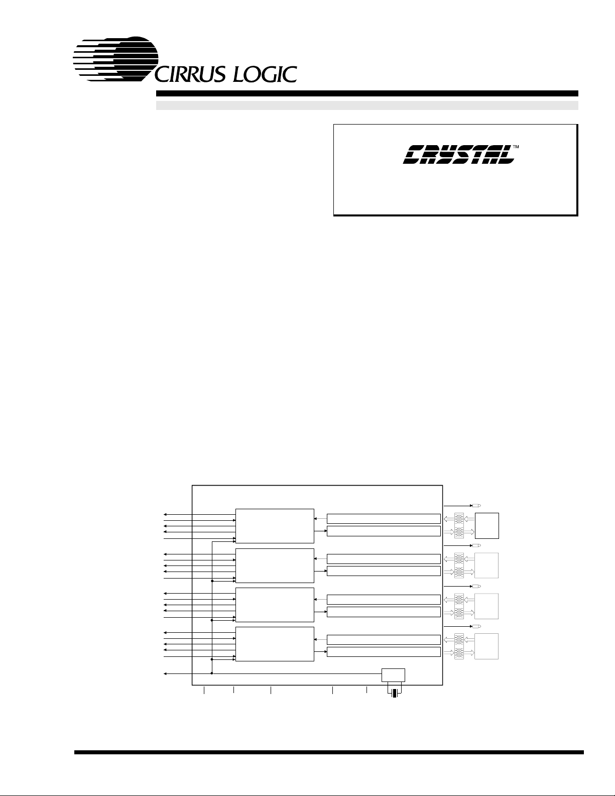
The CS8904 combines four 10BASE-T Ethernet ENDECs and transceivers into a single low-cost device.
Complete on-chip 10BASE-T Transceivers and filters
eliminate external com ponents, saving valuable boa rd
space and reducing cost. The CS8904 offers maximum
design flexibility by providing individual control and status lines for each of the four interface ports.
The CS8904 supports full-duplex operation, allowing simultaneous transmission and reception on all ports.
Auto-negotiation allows the automatic selection of either half or full duplex operation on a per-port basis.
The CS8904 is ideally suited for cost-sensitive Ethernet
switch designs. With the CS8904, engineers can design
a four-port Ethernet Transceiver circuit that occupies
less than 1.0 squa re inch (6.5 sq. cm) of spac e, excl usive of transformers and RJ-45 connectors.
STATUS (5)
TxDATA
RxDATA
RxCLK
CONTROL(4)
STATUS (5)
TxDATA
RxDATA
RxCLK
CONTROL(4)
STATUS (5)
TxDATA
RxDATA
RxCLK
CONTROL(4)
STATUS (5)
TxDATA
RxDATA
RxCLK
CONTROL(4)
TxCLK
CS8904 Quad Ethernet Transceiver
Encoder/Decoder & PLL
Encoder/Decoder & PLL
Encoder/Decoder & PLL
Encoder/Decoder & PLL
VDD(11) GND(13)
MODE(3)
10BASE-T RX Filters & Receiver
10BASE-T TX Filters &Transmitter
10BASE-T RX Filters & Receiver
10BASE-T TX Filters &Transmitter
10BASE-T RX Filters & Receiver
10BASE-T TX Filters &Transmitter
10BASE-T RX Filters & Receiver
10BASE-T TX Filters &Transmitter
RESET
RES
Clock
20 MHz XTAL
LINK LED
RJ-45 10BASE-T
LINK LED
RJ-45 10BASE-T
LINK LED
RJ-45 10BASE-T
LINK LED
RJ-45 10BASE-T
CIRRUS LOGIC ADVANCED PRODUCT DATABOOK
FEB ‘98 DS191PP2
Copyright Cirrus Logic, Inc. 1998
(All Rights Reserved)

Crystal LAN™ Quad Ethernet Transceiver
TABLE OF CONTENTS
1.0 INTRODUCTION.....................................................................................................3
1.1 General Description .........................................................................................................3
1.2 System Applications ........................................................................................................ 4
1.3 Key Features and Benefits ............................................................................................... 4
1.3.1 Low Cost, Low Noise, More Features.................................................................... 4
2.0 PIN DESCRIPTION.................................................................................................7
2.1 Controller Interface.......................................................................................................... 8
2.2 10BASE-T Interface ........................................................................................................ 9
2.3 LED Pins.......................................................................................................................... 9
2.4 General Pins..................................................................................................................... 9
3.0 THEORY OF OPERATION .................................................................................12
3.1 Overview........................................................................................................................ 12
3.2 Encoder/Decoder (ENDEC)........................................................................................... 12
3.2.1 Encoder ................................................................................................................ 13
3.2.2 Carrier Detection................................................................................................... 13
3.2.3 Clock and Data Recovery ..................................................................................... 13
3.3 10BASE-T Transceiver.................................................................................................. 13
3.3.1 10BASE-T Filters ................................................................................................. 14
3.3.2 Transmitter............................................................................................................ 14
3.3.3 Receiver ................................................................................................................ 14
3.3.4 Collision Detection ............................................................................................... 15
4.0 FUNCTIONAL DESCRIPTION...........................................................................16
4.1 Reset and Calibration..................................................................................................... 16
4.1.1 Reset Operation..................................................................................................... 16
4.1.2 Allowing Time for Reset....................................................................................... 16
4.2 Mode Control................................................................................................................. 16
4.3 Controller Interface........................................................................................................16
4.3.1 Transmit and Receive Interface ............................................................................ 16
4.3.2 Control and Status Information............................................................................. 17
4.4 External Clock Oscillator............................................................................................... 19
5.0 SPECIFICATIONS.................................................................................................20
ABSOLUTE MAXIMUM RATINGS................................................................................. 20
RECOMMENDED OPERATING CONDITIONS .............................................................20
DC CHARACTERISTICS................................................................................................... 20
DIGITAL INPUT/OUTPUT CHARACTERISTICS .......................................................... 21
SWITCHING CHARACTERISTICS - MODE 1................................................................ 22
SWITCHING CHARACTERISTICS - MODE 2................................................................ 24
SWITCHING CHARACTERISTICS - MODE 3................................................................ 26
SWITCHING CHARACTERISTICS - MODE 4................................................................ 28
SWITCHING CHARACTERISTICS - MODE 5................................................................ 30
10BASE-T CHARACTERISTICS...................................................................................... 32
CRYSTAL OSCILLATOR REQUIREMENTS.................................................................. 32
6.0 PACKAGE DIMENSIONS....................................................................................33
CS8904
CIRRUS LOGIC ADVANCED PRODUCT DATABOOK
2 DS191PP2
CS8904
T
T
T
T
Crystal LAN™ Quad Ethernet Transceiver
1.0 INTRODUCTION
1.1 General Description
The CS8904 is a true single-chip quad Ethernet
interface solution, incorporating all analog and
digital circuitry needed for a complete Ethernet
front end circuit. It includes high-performance onchip filtering, eliminating the need for external
filters. In addition, the CS8904 supports the latest
IEEE Ethernet features including full duplex and
Auto-Negotiation.
CS8904
The CS8904 incorporates four independent
Manchester encoder/decoders (ENDEC), clock
recovery circuits, 10BASE-T transceivers, and link
status LED circuits. The 10BASE-T transceivers
include drivers, receivers, and high-performance
on-chip analog filters, allowing direct connections
to low-cost isolation transformers. The CS8904’s
superior EMI characteristics are a result of the
high-quality receive and transmit filters which
eliminate the need for external fi lter packs and help
to make FCC Part 15, Class B compliance easier to
achieve. Each of the four transceivers support half
and full duplex operation and include IEEEcompliant Auto-Negotiation capability.
20 MHz
XTAL
RJ-45
10BASE-
W
LINKLED
S
I
T
C
H
I
N
G
B
U
S
SYSTEM
ASIC
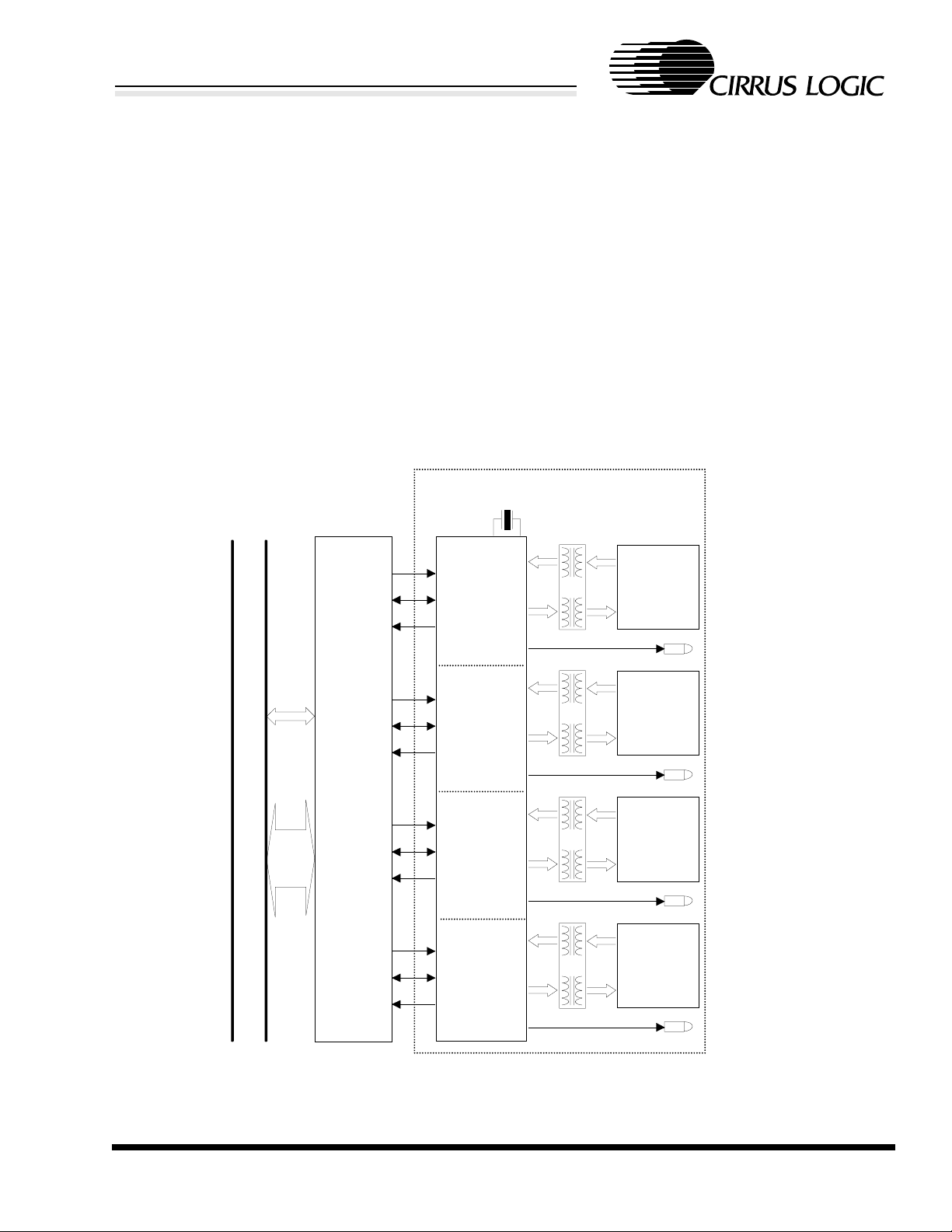
Figure 1. Ethernet Switching Hub Application of CS8904
RJ-45
RJ-45
RJ-45
10BASE-
LINKLED
10BASE-
LINKLED
10BASE-
LINKLED
CIRRUS LOGIC ADVANCED PRODUCT DATABOOK
DS191PP2 3

CS8904
Crystal LAN™ Quad Ethernet Transceiver
Each of the CS8904 interface ports support 100,
120, and 150 Ω shielded and unshielded cables, and
automatic receive reverse-polarity detection and
correction.
1.2 System Applications
The CS8904 is designed for use in Ethernet switch,
hub, and router systems and in ATM switches with
Ethernet support. Offering the latest features of the
IEEE 802.3 specification (ISO/IEC 8802-3:1996),
the CS8904 can be easily interfaced to custom
digital system ASICs. Inputs to the CS8904 from
the digital system ASIC are: transmit data, transmit
enable, duplex selection, auto-negotiation
selection, and loopback selection (loopback from
digital system ASIC through CS8904 to digital
system ASIC), and mode selection. Mode selection
allows the CS8904 to operate with a variety of
compatible Ethernet controllers.
Outputs of the CS8904 to the digital system ASIC
are: transmit clock, receive clock, receive data, and
five status lines: collision detect, carrier detect,
jabber indication, duplex (half / full), and autonegotiation (active / inactive).
The Link Status LED indicates that there is an
operational link with the remote network device.
1.3 Key Features and Benefits
1.3.1 Low Cost, Low Noise, More Features
• High-performance on-chip 10BASE-T filters
allow designers to use simple isolation transformers instead of more costly filt er/transformer packages.
• The CS8904 is designed to be used on a 4-layer
circuit board instead of a more expensive multilayer board, saving board manufacturing costs.
• The CS8904 has been designed for very low
noise emission. As a result FCC testing and
qualification time is reduced considerably.
• Half and full duplex operation make the
CS8904 ideal for use in 10BASE-T Ethernet
switch designs and in ATM switch systems that
require 10BASE-T Ethernet ports.
• Auto-Negotiation capability that is fully compliant with the latest IEEE Ethernet specification (ISO/IEC 8802-3:1995(u)) provides the
newest Ethernet features to system designers.
CIRRUS LOGIC ADVANCED PRODUCT DATABOOK
4 DS191PP2
CS8904
Crystal LAN™ Quad Ethernet Transceiver
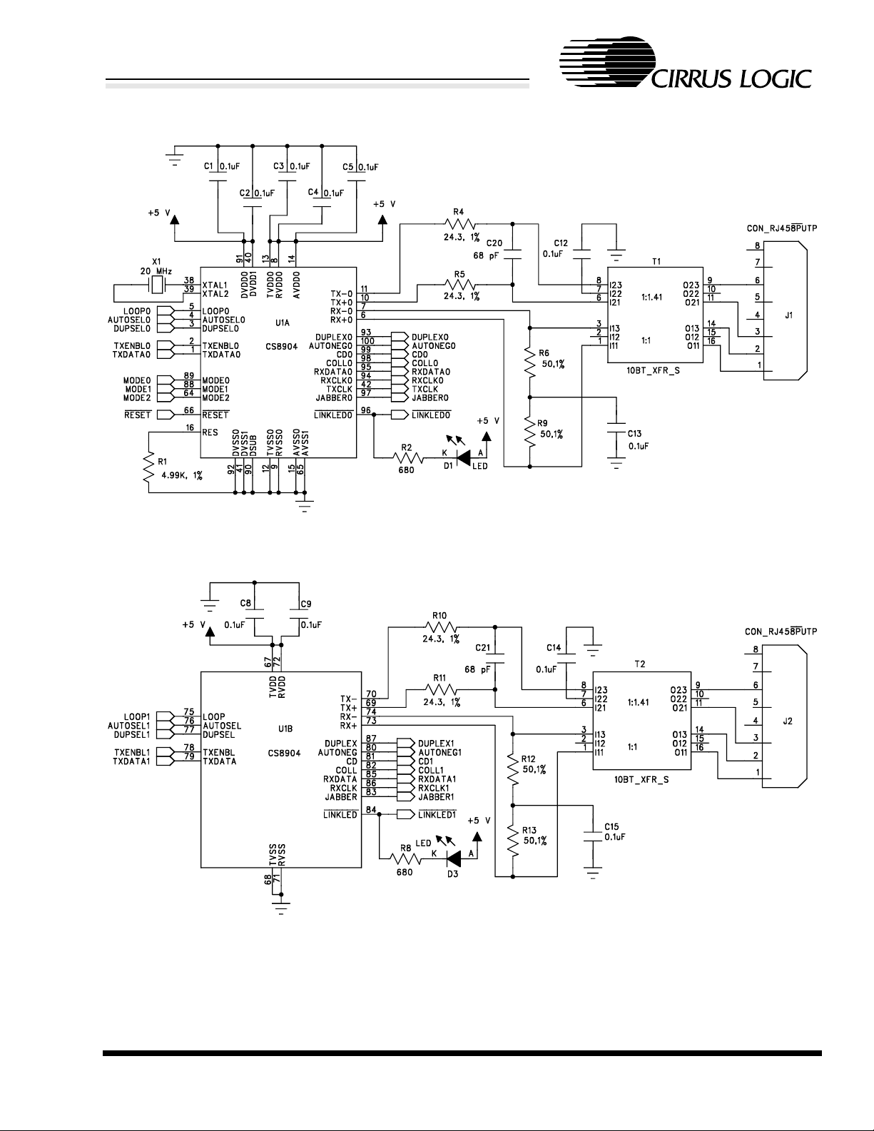
Port A
Port B
Figure 2. Typical Connection Diagram
CIRRUS LOGIC ADVANCED PRODUCT DATABOOK
DS191PP2 5
CS8904
Crystal LAN™ Quad Ethernet Transceiver
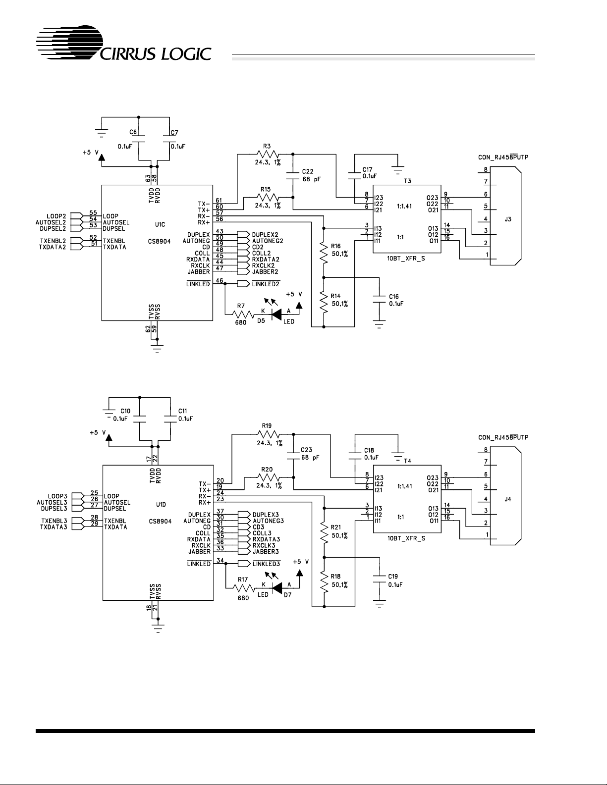
Port C
Port D
Figure 2. Typical Connection Diagram (continued)
CIRRUS LOGIC ADVANCED PRODUCT DATABOOK
6 DS191PP2
CS8904
Crystal LAN™ Quad Ethernet Transceiver
2.0 PIN DESCRIPTION
CD1
COLL1
JABBER1
LINKLED1
RxDATA1
RCLK1
DUPLEX1
MODE1
MODE0
DSUB
DVDD0
DVSS0
DUPLEX0
RCLK0
RxDATA0
LINKLED0
JABBER0
COLL0
CD0
AUTONEG0
81
82
83
84
85
86
87
88
89
90
91
92
93
94
95
96
97
98
99
100
AUTONEG1
TxDATA1
807978
123
TXENBL1
AUTOSEL1
DUPSEL1
76
5
LOOP1
RVDD1
Rx1-
Rx1+
RVSS1
75
747372
717770696867666564
678910411
Tx1-
Tx1+
TVSS1
CS8904
100-Pin
MQFP
121314
TVDD1
(Q)
151617
RESET
MODE2
AVSS1
TVDD2
TVSS2
636261
181920
Tx2-
Tx2+
RVSS2
RVDD2
6059585756
2122232425
Rx2-
Rx2+
LOOP2
555453
2627282930
AUTOSEL2
DUPSEL2
TxENBL2
51
52
TxDATA2
50
49
48
47
46
45
44
43
42
41
40
39
38
37
36
35
34
33
32
31
AUTONEG2
CD2
COLL2
JABBER2
LINKLED2
RxDATA2
RCLK2
DUPLEX2
TCLK
DVSS1
DVDD1
XTAL2
XTAL1
DUPLEX3
RxCLK3
RxDATA3
LINKLED3
JABBER3
COLL3
CD3
RVDD0
Tx0-
Tx0+
RVSS0
TVSS0
RX0-
Rx0+
LOOP0
TxENBL0
TxDATA0
DUPSEL0
AUTOSEL0
RES
TVDD0
AVSS0
AVDD0
TVDD3
Tx3-
Tx3+
TVSS3
Rx3-
Rx3+
RVSS3
LOOP3
RVDD3
AUTOSEL3
TxENBL3
DUPSEL3
TxDATA3
AUTONEG3
Figure 3. CS8904 Pin Diagram
CIRRUS LOGIC ADVANCED PRODUCT DATABOOK
DS191PP2 7

Crystal LAN™ Quad Ethernet Transceiver
2.1 Controller Interface
DUPSEL[0:3] - Duplex Select. Input, Pins 3, 77, 53, and 27.
When AUTOSEL is low, setting this pin high will force the port into full duplex operation and
setting this pin low will force the port into half duplex operation. When AUTOSEL is high,
setting this pin high indicates that full and half duplex capability should be advertised, and
setting this pin low indicates that only half duplex capability should be advertised.
AUTOSEL[0:3] - Auto-Negotiation Select. Input, Pins 4, 76, 54, and 26.
Setting this pin high will cause the port to Auto-Negotiate, automatically selecting half or full
duplex operation. When low, Auto-Negotiation is disabled and the duplex of the port is
controlled by the DUPSEL pin.
LOOP[0:3] - Port Loopback Enable. Input, Pins 5, 75, 55, and 25.
Port Loopback Enable: Setting this pin high will cause the input data on the TxDATA pin for
this port to appear on the RxDATA pin for this port. Tx+ and Tx- will remain idle and any data
received on Rx+ and Rx- will be ignored. Setting this pin low will result in normal operation of
the port.
CS8904
TxENBL[0:3] - Transmit Enable. Input, Pins 2, 78, 52, and 28.
Transmit Enable: When this pin is asserted, the input data for this port, present on the TxDATA
pin, is input to the CS8904 using the transmit clock, TxCLK. When this pin is deasserted, Tx+
and Tx- output pins are idle.
TxDATA[0:3] - Transmit Data. Input, Pins 1, 79, 51, and 29.
The data to be transmitted is presented on this pin using NRZ encoding and synchronized by
the transmit clock, TxCLK. Data is accepted when TxENBL is high.
TxCLK - Transmit Clock. Output with 4 mA drive, Pin 42.
Common transmit clock for all four ports. TxENBL is used to control the sampling of TxDATA
using TxCLK.
COLL[0:3] - Collision Detect Status. Output with 4 mA drive, Pins 98, 82, 48, and 32.
This output pin will assert to indicate that a collision has been detected on this port and
deasserts when the collision is no longer present. When operating in full duplex mode,
collisions will not occur and COLL will not transition.
CD[0:3] - Carrier Detect Status. Output with 4 mA drive, Pins 99, 81, 49, and 31.
This output pin is asserted while receive data is available on the RxDATA pin for this port.
DUPLEX[0:3] - Duplex Status. Output with 4 mA drive, Pins 93, 87, 43, and 37.
This output remains high when the port is operating full duplex, and remains low when the port
is operating half duplex.
CIRRUS LOGIC ADVANCED PRODUCT DATABOOK
8 DS191PP2

CS8904
Crystal LAN™ Quad Ethernet Transceiver
AUTONEG[0:3] - Auto-Negotiation Status. Output with 4 mA drive, Pins 100, 80, 50, and 30.
This output remains high when Auto-Negotiation has taken place successfully, and remains low
when Auto-Negotiation has failed or is disabled for this port. See Section 4.3.2 (Control and
Status Information) for more information.
RxDATA[0:3] - Re ceived Data. Output with 4 mA drive, Pins 95, 85, 45, and 35.
The data received for this port is output on this pin. This data is NRZ encoded and is
synchronized using the receive clock, RxCLK. The CD pin is asserted when receive data is
present on the RxDATA pin.
JABBER[0:3] - Jabber. Output with 4 mA drive, Pins 97, 83, 47, and 33.
This output pin will assert to indicate that a jabber condition has been detected for this port.
RxCLK[0:3] - Recovered Receive Clock. Output with 4 mA drive, Pins 94, 86, 44, and 36.
The recovered receive clock for the port is output on this pin.
2.2 10BASE-T Interface
TX+[0:3], TX-[0:3] - 10BASE-T Transmit Pair. Output, Pins 10, 69, 60, 19, 11, 70, 61, and 20.
Differential output pair that drives 10 Mb/s Manchester-encoded data to the 10BASE-T twistedpair segment.
RX+[0:3], RX-[0:3] - 10BASE-T Receive Pair. Input, Pins 6, 73, 56, 23, 7, 74, 57, and 24.
Differential input pair that receives 10 Mb/s Manchester-encoded data from the 10BASE-T
twisted-pair segment.
2.3 LED Pins
LINKLED[0:3] - Link Status LED. Open Drain Output with 10 mA drive, Pins 96, 84, 46, and 34.
This active-low output goes low and remains continuously low for a functioning 10BASE-T
link. Refer to Section 4.3.2 (Control and Status Information) for more information on using the
LINKLED pin.
2.4 General Pins
XTAL1, XTAL2 - Crystal. Input, Output, Pins 38 and 39.
A 20 MHz crystal should be connected across these pins. Alternatively, a 20 MHz signal may
be connected to XTAL1; XTAL2 is left open.
RESET - Reset. Input with Internal Weak Pullup, Pin 66.
Setting this pin low for at least 500 ns will reset the CS8904.
CIRRUS LOGIC ADVANCED PRODUCT DATABOOK
DS191PP2 9

MODE[0:2] - Mode Select. Input, Pins 89, 88, and 64.
Selects the controller compatibility mode. See Table 1.
RES - Reference Resistor. Input, Pin 16.
A 4.99 kΩ ±1% resister should be connected between this input and ground.
AVDD - Analog Power. Power, Pin 14.
Provides power to the analog circuits of the CS8904.
AVSS0, AVSS1 - Analog Ground. Ground, Pins 15 and 65.
Provides a ground reference (0 V) to the analog circuits of the CS8904.
DVDD0, DVDD1 - Digital Power. Power, Pins 91 and 40.
Provides power to the digital circuits of the CS8904.
DVSS0, DVSS1 - Digital Ground. Ground, Pins 92 and 41.
CS8904
Crystal LAN™ Quad Ethernet Transceiver
Provides a ground reference (0 V) to the digital circuits of the CS8904.
TVDD[0:3] - Transmitter Analog Power. Power, Pins 13, 67, 63, and 17.
Provides power to the transmitter analog circuits of the CS8904.
TVSS[0:3] - Digital Ground. Ground, Pins 12, 68, 62, and 18.
Provides a ground reference (0 V) to the transmitter analog circuits of the CS8904.
RVDD[0:3] - Receiver Analog Power. Power, Pins 8, 72, 58, and 22.
Provides power to the receiver analog circuits of the CS8904.
RVSS[0:3] - Receiver Analog Ground. Ground, Pins 9, 71, 59, and 21.
Provides a ground reference (0 V) to the receiver analog circuits of the CS8904.
DSUB - Ground. Ground, Pin 90.
Provides ground to the substrate layer of the CS8904.
CIRRUS LOGIC ADVANCED PRODUCT DATABOOK
10 DS191PP2
CS8904
Crystal LAN™ Quad Ethernet Transceiver
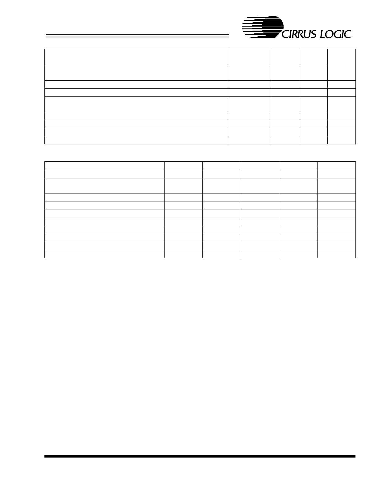
Mode
Controller Compatibility
Advanced Micro Devices AM7990, Motorola 68EN360, or
compatible controllers
Intel 82586, Intel 82596, or compatible controllers Mode 2 1 0 1
Fujitsu MB86950, Fujitsu MB86960, or compatible controllers Mode 3 1 1 0
National Semiconductor 8390, Texas Instruments TMS380C26, or
compatible controllers
Seeq 8005 or compatible controller Mode 5 0 1 1
Reserved; Operation Undefined 0 1 0
Reserved; Operation Undefined 0 0 1
Reserved; Operation Undefined 0 0 0
Table 1. Mode Selection Summary
Parameter Mode 1 Mode 2 Mode 3 Mode 4 Mode 5
Mode Bits (MODE2, MODE1, MODE0) 1 0 0 1 0 1 1 1 0 1 1 1 0 1 1
Controller Compatibility AMD
Motorola
Edge of TxCLK where TxDATA is sampled Rising Falling Falling Rising Rising
Polarity of Active TxENBL High Low High High High
Polarity of Active LOOP High Low High High High
Polarity of Active COLL High Low Low High High
Edge of RxCLK where RxDATA is clocked. Rising Falling Falling Rising Rising
Polarity of Active CD High Low High High High
Level of RxDATA when CD is deasserted High High Low Low Low
RxCLK after CD is deasserted 5 cycles 5 cycles Continuous 5 cycles Continuous
Ta ble 2. Mode Operation Comparison
Intel Fujitsu National
Selected
Mode 1 1 0 0
Mode 4 1 1 1
MODE2
Pin
MODE1
TI
Pin
MODE0
Pin
SEEQ
CIRRUS LOGIC ADVANCED PRODUCT DATABOOK
DS191PP2 11

CS8904
Crystal LAN™ Quad Ethernet Transceiver
3.0 THEORY OF OPERATION
3.1 Overview
The CS8904 provides four independent ports for a
multi-port Ethernet system logic device. In t erms of
the IEEE 802.3 specification, the CS8904
combines the functions of the Physical Signaling
sublayer (PLS) and the 10BASE-T Medium
Attachment Unit (MAU) for four independent
interface into a single device. Typically, the system
logic device provides multiple Media Access
Control (MAC) interfaces, which connect to the
CS8904. For simplicity, a single port interface of
this system logic device is referred to as a digital
controller throughout this datasheet.
A synchronous bit-serial stream of data is received
and transmitted between the CS8904 and the digital
controller. Digital information that is sent to the
CS8904 from the digital controller is Manchester
encoded and transmitted over the 10BASE-T
wiring system. Data received from the 10BASE-T
wiring system is converted to serial data which is
sent as a bit-serial stream, along with the clock
recovered from the data, to the Ethernet system
logic. Additionally, status and control information
is exchanged between the CS8904 and the Ethernet
digital controller. All ports operate independently,
allowing features such as duplex selection, AutoNegotiation, and loopback to operate on a per-port
basis.
The CS8904 also incorporates full IEEE-compliant
transmit and receive filtering internally. No
external filters are required and simple isolation
transformers may be used with the 10BASE-T
ports.
3.2 Encoder/Decoder (ENDEC)
The CS8904’s integrated encoder/decoder
(ENDEC) circuit is compliant with the relevant
portions of clause 7 of the Ethernet standard
(ISO/IEC 8802-3, 1996). Its primary functions
include performing Manchester encoding of
transmit data, informing the controller when valid
receive data is present (Carrier Detection), and
recovering the clock and NRZ data from incoming
Manchester-encoded data.
Figure 4 provides a block diagram of the ENDEC
and illustrates how it interfaces to the digital
controller and 10BASE-T transceiver.
ENDEC
CD
RxCLK
System
ASIC
12 DS191PP2
RxDATA
TxCLK
TxDATA
TxENBL
COLL
CIRRUS LOGIC ADVANCED PRODUCT DATABOOK
Carrier
Detector
Decoder
& PLL
Encoder
Clock
Figure 4. ENDEC
RX
TX
10BASE-T
Transceiver

CS8904
Crystal LAN™ Quad Ethernet Transceiver
3.2.1 Encoder
The encoder converts NRZ data from the digital
controller and a 10 MHz Transmit Clock signal into
a serial stream of Manchester da ta. The Transmit
Clock is produced by an on-chip oscillator circuit
that is driven by either an external 20 MHz quartz
crystal or a TTL-level CMOS clock input. The
encoded signal is routed to the 10BASE-T
transceiver.
3.2.2 Carrier Detection
The internal Carrier Detection circuit informs the
digital controller that valid receive data is present
by asserting the Carrier Detect (CD) signal as soon
it detects a valid Ethernet preamble. During normal
packet reception, Carrier Detect remains asserted
while the frame is being received, and is deasserted after the last low-to-high transition of the
End-of-Frame (EOF) sequence. Whenever the
receiver is idle (no receive ac tivi ty), Carrie r Detec t
remains de-asserted.
3.2.3 Clock and Data Recovery
When the receiver is idle, the phase-lock loop
(PLL) is locked to the internal clock signal. The
assertion of the Carrier Sense signal interrupts the
PLL. When it restarts, it locks on the incoming
data. The receive clock is then compared to the
incoming data at the bit cell center and any phase
difference is corrected. The PLL remains locked as
long as the receiver input signal is valid. Once the
PLL has locked on the incoming data, the ENDEC
converts the Manchester data to NRZ and passes
the decoded data and the recovered clock to the
digital controller for further processing.
3.3 10BASE-T Transceiver
The CS8904 includes integral 10BASE-T
transceivers that are compliant with the relevant
portions of clause 14 of the Ethernet standard
(ISO/IEC 8802-3:1996). It includes all analog and
digital circuitry needed to interface the CS8904
directly to a simple isolation transformer (see
Figure 2 for a connection diagram). Figure 5
provides a block diagram of one of the 10BASE-T
transceivers.
Auto-Negotiation and Link
Control and Status
Auto-Negotiation
and Link Pulse
RX
ENDEC
TX
CIRRUS LOGIC ADVANCED PRODUCT DATABOOK
DS191PP2 13
TX Pre-
Distortion
Figure 5. 10BASE-T Transceiver
10BASE-T Transceiver
RX
Comparator
TX Filters
Filter Tuning
RX Filters
TX Drivers
Rx+
Rx-
Tx+
Tx-

CS8904
Crystal LAN™ Quad Ethernet Transceiver
3.3.1 10BASE-T Filters
Each of the CS8904’s 10BASE-T transceivers
include integrated low-pass transmit and receive
filters, eliminating the need for external filters or a
filter/transformer hybrid. On-chip filters are active
(gm/c) implementations of fifth-order Butterworth
low-pass filters. Internal tuning circuits keep the
gm/c ratio tightly controlled, even when large
temperature, supply, and IC process variations
occur. The nominal 3 dB cutoff frequency of the
filters is 16 MHz, and the nominal attenuation at 30
MHz (3rd harmonic) is -27 dB.
3.3.2 Transmitter
During transmission, Manchester encoded data
from the ENDEC is fed into the transmitter’s predistortion circuit where initial wave shaping and
pre-equalization is performed. The output of the
pre-distortion circuit is fed into the transmit filter
where final wave shaping occurs and unwanted
noise is removed. The signal then passes to the
differential driver where it is amplified and driven
out of the Tx+/Tx- pins.
In the absence of transmit packets, the transmitter
generates Normal Link Pulses (NLP) in accordance
with clause 14.2.1.1 of the Ethernet standard
(ISO/IEC 8802-3:1996).
If no link pulses or Ethernet frames are being
received on the receiver, the 10BASE-T transmitter
is internally forced to an inactive state.
3.3.3 Receiver
The 10BASE-T receive section consists of the
receive filter, squelch circuit, polarit y detection and
correction circuit, and link pulse detector.
less than the squelch threshold (either positive or
negative, depending on polarity) is rejected.
3.3.3.2 Auto-Negotiation and Link Pulses
The CS8904 supports Auto-Negotiation, the
mechanism that allows the two devices on either
end of a 10BASE-T link segment to share
information and automatically configure both
devices for maximum performance. The CS8904
Auto-Negotiation capability is fully compliant with
the relevant portions of clause 28 of the Ethernet
standard (ISO/IEC 8802-3:1995(u)).
Auto-Negotiation encapsulates information within
a burst of closely spaced link integrity test pulses,
referred to as a Fast Link Pulse (FLP) Burst. The
FLP Burst consists of a series of link integrity pulses
which form an alternating clock / data sequence.
Extraction of the data bits from the FLP Burst yields
a Link Code Word which identifies the capabi lity of
the remote device. To remain interoperable with
existing 10Base-T devices, the CS8904 also
supports the reception of 10Base-T compliant link
integrity test pulses, referred to as Normal Link
Pulses (NLP).
When configured for Auto-Negotiation, the
CS8904 will detect and automatically operate fullduplex if the device on the other end of the link
segment also supports full-duplex and AutoNegotiation. If the remote device supports AutoNegotiation, but only advertises half duplex
capability, the CS8904 will operate half duplex.
Once Auto-Negotiation has completed
successfully, the CS8904 will send Normal Link
Pulses. The CS8904 Normal Link Pulse operation
is fully compliant with clause 14.2.1.1 of the
Ethernet specification (ISO/IEC 8802-3:1996).
3.3.3.1 Squelch Circuit
The 10BASE-T squelch circuit determines when
valid data is present on the Rx+/Rx- pair. Incoming
signals passing through the receive filter are tested
by the squelch circuit. Any signal with amplitude
CIRRUS LOGIC ADVANCED PRODUCT DATABOOK
14 DS191PP2
The CS8904 supports parallel detection. Devices
that respond to the CS8904’s attempt to AutoNegotiate with Normal Link Pulses cause the
CS8904 to respond with Normal Link Pulses and to
operate as a 10BASE-T half-duplex device.

CS8904
Crystal LAN™ Quad Ethernet Transceiver
If the remote device supports Auto-Negotiation,
but does not share a compatible set of capabilities
with the CS8904, then the CS8904 will indicate
that the Auto-Negotiation was unsuccessful and
that the link is failed th roug h the Auto-Negotia tion
output and the Link Status LED output. Autonegotiation may also fail if the CS8904 is unable to
exchange a Link Code Word with the remote
device.
When Auto-Negotiation is disabled, the CS8904
sends Normal Link Pulses to the remote Ethernet
device.
3.3.3.3 Receive Polarity Detection and Correction
The CS8904 checks the polarity of the receive half
of the twisted pair cable and automatically correc ts
a reversal.
To detect a reversed pair, the receiver examines
received link pulses and the End-of-Frame (EOF)
sequence of incoming packets. If it detects at least
one reversed link pulse and at least four frames in a
row with negative polarity after the EOF, the
receive pair is considered reversed. Any data
received before the correction of the reversal is
ignored.
3.3.4 Collision Detection
If half duplex operation is selected, the CS8904
detects a 10BASE-T collision whenever the
receiver and transmitter are active simultaneously.
When a collision is present, the collision detection
circuit informs the digital controller by asserting
the collision signal. If full duplex operation is
selected, the collision detection circuit is disabled.
CIRRUS LOGIC ADVANCED PRODUCT DATABOOK
DS191PP2 15

CS8904
Crystal LAN™ Quad Ethernet Transceiver
4.0 FUNCTIONAL DESCRIPTION
4.1 Reset and Calibration
4.1.1 Reset Operation
Three different conditions cause the CS8904 to
reset its internal circuits:
Power-Up Reset: When power is applied, the
CS8904 maintains reset until the voltage at the
supply pins reaches approximately 2.5 V. The
CS8904 comes out of reset once Vcc is greater than
approximately 2.5 V and the crystal osci llator has
stabilized.
Power-Down Reset: If the supply voltage drops
below approximately 2.5 V, there is a chip-wide
reset. The CS8904 remains in a reset state until the
power supply returns to a level greater than
approximately 2.5 V and the crystal osci llator has
stabilized.
External Reset: There is a chip-wide reset
whenever the RESET pin is held low for at least
500 ns.
4.1.2 Allowing Time for Reset
After a reset, the CS8904 resets all internal
circuitry and calibrates all on-chip analog circuitry.
The time required for the reset and calibration is
typically 36 ms. During this time, the TxCLK
signal is held low. When the reset and calibration
operations are complete, the TxCLK signal
operates as normal, oscillating at a frequency of 10
MHz.
4.2 Mode Control
The CS8904 is designed to operate with a number
of industry standard Ethernet controllers and
compatible devices. It is compatible with
controllers from Advanced Micro Devices (AMD),
Intel, Fujitsu, Seeq, National Semiconductor and
Texas Instruments.
The MODE2, MODE1, and MODE0 pins allow
five different compatibility modes to be enabled for
the CS8904. Mode selection affects the control
signal timing and polarities of the four ports of the
CS8904. Table 1 summarizes the various modes
and the MODE2, MODE1, and MODE0 pin
settings required to select them.
4.3 Controller Interface
The CS8904 provides four independent interfaces
for the digital controllers. In addition to providing
a mechanism to transfer synchronous serial data
between the CS8904 and the controller, each
interface also provides control and status
information for the port.
4.3.1 Transmit and Receive Interface
4.3.1.1 Normal Transmission
The CS8904 receives serial data from the controller
on the TxDATA pin. This data is synchronized by
the transmit clock present on the TxCLK pin. Only
one transmit clock signal is provided from the
CS8904, thus the TxCLK signal is shared by the
four interface ports. The controller causes a
transition to occur on the TxENBL pin, indicating
the start and completion of the data to be
transmitted. When a port is operating half duplex,
the transmitted data is looped back to the controller
during transmission on the RxDATA pin,
synchronized by the receive clock present on the
RxCLK pin. This is referred to as MAU loopback
to distinguish it from the Port Loopback capability
described in Section 4.3.2 (Control and Status
Information) below.
4.3.1.2 Jabber Indication
If the serial data provided by the controller to the
CS8904 continues for greater than 100 ms, the
CS8904 will terminate the transmission of data to
the network, disable the MAU loopback of
transmitted data on the RxDATA pin, and indicate
this condition by raising the JABBER pin. The
CIRRUS LOGIC ADVANCED PRODUCT DATABOOK
16 DS191PP2

CS8904
Crystal LAN™ Quad Ethernet Transceiver
CS8904 will keep the transmitter disabled until
TxENBL has been deasserted and TxDATA has
been idle for at least 420 ms.
4.3.1.3 Collision Indication
When operating half duplex, the reception of data
from the network during the normal transmission
of data indicates a collision has occurred. If this
condition is detected, the CS8904 will cause the
COLL pin to be raised. Following that, when the
CS8904 detects a transition on the TxENBL pin or
the termination of the data received on the Rx+ /Rxpins, then the CS8904 will cause the COLL pin to
deassert. Normally, the COLL signal is used by the
controller to, among other things, initiate a jam
sequence. (An arbitrary set of bits of sufficient
number to assure that all communicating stations
detect a collision.)
Note that, by definition, collisions cannot occur
when operating full duplex.
4.3.1.4 Normal Reception
Received data is provided to the controller on the
RxDATA pin. The data is synchronized by the
clock recovered from the Manchester encoded data
received from the 10BASE-T Ethernet network.
The receive clock is output on the RxCLK pin. The
CS8904 indicates the beginning and ending of the
reception of valid data by causing a transition of the
CD pin.
4.3.2 Control and Status Information
Control and status signals are provided to select
and monitor the operational characteristics of each
port.
4.3.2.1 Auto-Negotiation and Duplex Selection
Auto-Negotiation allows the CS8904 to
communicate with the remote Ethernet device to
select the highest common duplex capability that
the two devices share. The CS8904 is fully
compliant with the relevant portions of section 28
of the Ethernet standard (ISO/IEC 88023:1995(u)). Auto-Negotiation may be configured
differently for each individual port of the CS8904.
Setting the AUTOSEL pin high indicates that the
port will attempt to Auto-Negotiate duplex
selection with the remote end of the link. The
capability that will be advertised for this port is
determined by the DUPSEL pin. Setting the
DUPSEL pin high indicates that half or full duplex
capability may be negotiated. Setting the DUPSEL
pin low indicates that only half duplex capability
may be negotiated.
Setting the AUTOSEL pin low indicates that AutoNegotiation on the port is disabled. The DUPSEL
pin then determines the duplex operation of the
port. If the DUPSEL pin is set high, then the port
will only operate full duplex, otherwise if the
DUPSEL is set low, then the port will only operate
half duplex.
In either case, the outcome of duplex selection is
available for the controller on the DUPLEX and
AUTONEG pins. The DUPLEX pin indicates that
the port is operating half duplex if the output is low
and indicates that the port is operating full duplex
if the output is high. The AUTONEG pin indicates
whether the duplex selection occurred as a result of
a successful negotiation, as a result of explicit
selection using the DUPSEL pin, or as the result of
a failed attempt to Auto-Negotiate. Table 3
illustrates the possible outputs of the AUTONEG
and DUPLEX pins and their respective meanings.
CIRRUS LOGIC ADVANCED PRODUCT DATABOOK
DS191PP2 17
Crystal LAN™ Quad Ethernet Transceiver
DUPSEL AUTOSEL DUPLEX AUTONEG Result Indicated
Low Low Low Low Forced Half Duplex Operation
High Low High Low Forced Full Duplex Operation
Low High Low High Successful Auto-Negotiation; Half Duplex Operation Selected
High High High High Successful Auto-Negotiation; Full Duplex Operation Selected
High High Low High Successful Auto-Negotiation; Half Duplex Operation Selected
X High Low Low Unsuccessful Auto-Negotiation; Link Not Operational Selected
Table 3. Auto-Negotiation and Duplex Selection
4.3.2.2 Changes to Duplex and Auto-Negotiation
Selections
+5 V
The duplex and Auto-Negotiation selection may be
changed, even after an Auto-Negotiation sequence
has established a good link between a port on the
CS8904 and a remote Ethernet device. The CS8904
LINKSTAT
allows the system designer to dynamically alter
these selections at any time. The CS8904 will
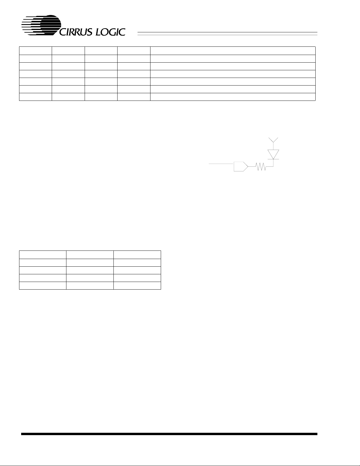
Figure 6. LED Connection Diagram
immediately reconfigure the port to the specified
duplex and Auto-Negotiation operation, renegotiating with the remote Ethernet device if
appropriate. Table 4 summarizes the operation of
Auto-Negotiation as a result of various transitions
of the DUPSEL or AUTSEL pins.
The LINKLED pin can be used by the controller to
determine if a port has established a valid link with
the remote 10BASE-T device. This pin will be
driven low when a valid link has been established.
Detailed information regarding the duplex selected
and whether the selection was a result of Auto-
DUPLEX AUTOSEL Re-Negotiation
Transition Low No
Transition High Yes
X Low to High Yes
X High to Low No
Table 4. Auto-Negotiation Operation
Negotiation is available from the DUPLEX and
AUTONEG pins, as described earlier in this
section. If the capabilities selected by the controller
for a port are not compatible with a remote Ethernet
device, then a valid link will not be established and
the LINKLED will be held high.
4.3.2.3 Link Status Information
4.3.2.4 Port Loopback
The LINKLED pin provides an LED output to
indicate that a link has been successfully
established with the remote Ethernet device. This
may occur as a result of normal 10BASE-T
operation or as a result of a successful AutoNegotiation. This LED output is capable of sinking
10 mA to drive an LED directly through a series
resistor. The output voltage of each pin is less than
0.4 V when the pin is low. Figure 6 shows a typical
LED circuit.
The CS8904 allows each individual port to be
placed in a loopback mode. Note that this feature is
different from MAU loopback, which is the
loopback that occurs during the normal
transmission of data when operating half duplex.
The Port Loopback feature provides a mechanism
to perform network fault isolation and problem
analysis in an Ethernet system device. Port
Loopback may also be used as a means to disable
(partition) a port from the external network. Setting
the LOOP pin high enables this feature.
CS8904
CIRRUS LOGIC ADVANCED PRODUCT DATABOOK
18 DS191PP2

CS8904
Crystal LAN™ Quad Ethernet Transceiver
Port Loopback causes the 10BASE-T transmitter to
be idled and the 10BASE-T receiver to be
disconnected. In addition, data received from the
controller on the TxDATA pin is looped back on
the RxDATA pin to the controller. Both CD and
RxCLOCK are provided to synchronize the
transfer to the controller. Note that since the port is
isolated from the external Ethernet network,
collisions will not occur.
4.4 External Clock Oscillator
A 20-MHz quartz crystal or CMOS clock input is
required by the CS8904. If a CMOS clock input is
used, it should be connected the to XTAL1 pin,
with the XTAL2 pin left open. The clock signal
should be 20 MHz ±0.01% with a duty cycle
between 45% and 55%. The specifications for the
crystal are described in the External Clock section
of the DC CHARACTERISTICS Table.
CIRRUS LOGIC ADVANCED PRODUCT DATABOOK
DS191PP2 19

5.0 SPECIFICATIONS
CS8904
Crystal LAN™ Quad Ethernet Transceiver
ABSOLUTE MAXIMUM RATINGS (AV
, DVSS = 0 V; all voltages with respect to 0 V.)
SS
Parameter Symbol Min Max Unit
Power Supply V
DD
-0.3 6.0 V
Input Current Except Supply Pins - ±10.0 mA
Input Voltage -0.3 V
+ 0.3 V
DD
Ambient Temperature Power Applied -55 +125 °C
Storage Temperature -65 +150 °C
WARNING: Operation at or beyond these limits may result in permanent damage to the device.
Normal operation is not guaranteed at these extremes.
RECOMMENDED OPERATING CONDITIONS (V
= 0 V; all voltages with respect to 0 V.)
SS
Parameter Symbol Min Max Unit
Power Supply CM5
CM3
Operating Ambient Temperature T
V
DD
V
DD
A
4.75
3.00
5.25
3.6
070°C
DC CHARACTERISTICS (Over Recommended Operating Conditions.)
Parameter Symbol Min Typ Max Unit
Power Supply
Power Supply Current While Active All Ports Active I
Power Supply Current While Idle No Ports Active I
DD
DDIDLE
Power Dissipated While Active - 1.37 - W
Transmit and Rece ive Clocks
TxCLK and RxCLK Output Rise and Fall Time (Note 1)
tR, t
F
CMOS
TTL
External Clock
XTAL1 Input Low Voltage V
XTAL1 Input High Voltage V
XTAL1 Input Low Current I
XTAL1 Input High Current I
XTAL1 Input Cycle Time t
XTAL1 Input Low Time V
XTAL1 Input High Time V
< 1.0 V t
IX
> 1.0 V t
IX
IXL
IXH
IXL
IXH
IXC
IXL
IXH
--340mA
--200mA
-
-
-
-
5
4
ns
ns
-0.3 - 0.8 V
2.0 - VDD +
0.5
-40 - - µA
--40µA
49.995 - 50.005 ns
22.5 - 27.5 ns
22.5 - 27.5 ns
V
V
V
Notes: 1. C
= 50 pF; Measurement at 20% and 80% points.
LOAD
t
IXC
t
IXL
t
IXH
XTAL1
CIRRUS LOGIC ADVANCED PRODUCT DATABOOK
20 DS191PP2

CS8904
Crystal LAN™ Quad Ethernet Transceiver
DIGITAL INPUT/OUTPUT CHARACTERISTICS (Over Recommended Operating Conditions.)
Parameter Symbol Min Max Unit
Output Low Voltage I
Output High Voltage I
Output Leakage Current 0 ≤ V
= 8 mA (Note 2)
OL
= 4 mA (Note 3)
I
OL
= -2 mA (Note 3) V
OH
OUT
≤ V
CC
(Note 2) I
Input Low Voltage Input
Input with Internal Weak Pullup
Input High Voltage Input
Input with Internal Weak Pullup
Input Leakage Current 0 ≤ V
IN
≤ V
CC
Input
Input with Internal Weak Pullup
Notes: 2. Open Drain Output with 10 mA drive.
3. Open Drain Output with 4 mA drive.
V
OL
-
-
OH
LL
V
IL
2.4 - V
-10 10 µA
-
-
V
IH
2.0
2.0
I
L
I
OL
-10
-20
0.4
0.4
0.8
0.8
-
-
10
10
V
V
V
V
V
V
µA
µA
CIRRUS LOGIC ADVANCED PRODUCT DATABOOK
DS191PP2 21

CS8904
Crystal LAN™ Quad Ethernet Transceiver
SWITCHING CHARACTERISTICS - MODE 1 (T
Parameter Symbol Min Max Unit
Receive Timing - Start of Frame
RX+/RX- active to RxDA TA active t
RX+/RX- active to CD active t
Receive data setup from RxCLK t
Receive data hold from RxCLK t
Receive Timing - End of Frame
RxCLK hold after CD off t
RxDATA throughput delay t
CD turn off delay t
Transmit Timing
TxENBL setup from TxCLK t
TxENBL hold after TxCLK t
TxDATA setup from TxCLK t
TxDATA hold after TxCLK t
Transmit startup delay t
Transmit throughput delay t
Loopback Timing
LOOP setup from TxENBL t
LOOP hold after TxENBL t
CD startup delay after TxENBL t
CDOFF
CHDU
= 25 °C; VDD = 5 V; Note 4.)
A
DATA
CD
RDS
RDH
RCH
RD
-1200ns
- 620 ns
35 - ns
50 - ns
5 - bit times
- 250 ns
- 400 ns
EHCH
CHEL
DSCH
10 - ns
10 - ns
10 - ns
10 - ns
STUD
TPD
KHEH
KHEL
CAEA
- 400 ns
- 400 ns
10 - ns
10 - ns
80 - ns
Notes: 4. COLL asserts active-high in Mode 1.
CIRRUS LOGIC ADVANCED PRODUCT DATABOOK
22 DS191PP2

CS8904
Crystal LAN™ Quad Ethernet Transceiver
RX+/RX-
CD
RxCLK
RxDATA
RX+/RX-
CD
RxCLK
RxDATA
10101010111
t
CD
t
DATA
101
Mode 1 Receive Timing - Start of Frame
10101010
t
RD
0110
1010100
01000101010
t
RDS
t
RDH
010101110
0
t
CDOFF
t
RCH
TxENBL
TxCLK
TxDATA
TX+/TX-
LOOP
TxENBL
CD
t
KHEH
t
EHCH
t
CAEA
Mode 1 Receive Timing - End of Frame
t
DSCH
t
CHDU
t
STUD
Mode 1 Transmit Timing
t
TPD
t
CHEL
t
KHEL
Mode 1 Loopback Timing
CIRRUS LOGIC ADVANCED PRODUCT DATABOOK
DS191PP2 23

CS8904
Crystal LAN™ Quad Ethernet Transceiver
SWITCHING CHARACTERISTICS - MODE 2 (T
Parameter Symbol Min Max Unit
Receive Timing - Start of Frame
RX+/RX- active to RxDA TA active t
RX+/RX- active to CD active t
Receive data setup from RxCLK t
Receive data hold from RxCLK t
Receive Timing - End of Frame
RxCLK hold after CD off t
RxDATA throughput delay t
CD turn off delay t
Transmit Timing
TxENBL setup from TxCLK t
TxENBL hold after TxCLK t
TxDATA setup from TxCLK t
TxDATA hold after TxCLK t
Transmit startup delay t
Transmit throughput delay t
Loopback Timing
LOOP setup from TxENBL t
LOOP hold after TxENBL t
CD startup delay after TxENBL t
CDOFF
CHDU
= 25 °C; VDD = 5 V; Note 5.)
A
DATA
CD
RDS
RDH
RCH
RD
-1300ns
- 800 ns
35 - ns
50 - ns
5 - bit times
- 250 ns
- 400 ns
EHCH
CHEL
DSCH
10 - ns
10 - ns
10 - ns
10 - ns
STUD
TPD
KHEH
KHEL
CAEA
- 400 ns
- 400 ns
10 - ns
10 - ns
255 - ns
Notes: 5. COLL asserts active-low in Mode 2.
CIRRUS LOGIC ADVANCED PRODUCT DATABOOK
24 DS191PP2

CS8904
Crystal LAN™ Quad Ethernet Transceiver
RX+/RX-
CD
RxCLK
RxDATA
RX+/RX-
CD
RxCLK
RxDATA
10101010111
t
CD
t
DATA
101
Mode 2 Receive Timing - Start of Frame
10101010
t
RD
01
1010101001
01000101010
t
RDS
t
RDH
010101110
0
t
CDOFF
t
RCH
TxENBL
TxCLK
TxDATA
TX+/TX-
LOOP
TxENBL
CD
t
t
KHEH
EHCH
t
CAEA
t
STUD
Mode 2 Receive Timing - End of Frame
t
DSCH
t
CHDU
t
TPD
Mode 2 Transmit Timing
t
KHEL
t
CHEL
Mode 2 Loopback Timing
CIRRUS LOGIC ADVANCED PRODUCT DATABOOK
DS191PP2 25

CS8904
Crystal LAN™ Quad Ethernet Transceiver
SWITCHING CHARACTERISTICS - MODE 3 (T
Parameter Symbol Min Max Unit
Receive Timing - Start of Frame
RX+/RX- active to RxDA TA active t
RX+/RX- active to CD active t
Receive data setup from RxCLK t
Receive data hold from RxCLK t
RxCLK shutoff delay from CD active t
Receive Timing - End of Frame
RxDATA throughput delay t
CD turn off delay t
RxCLK switching delay after CD off t
Transmit Timing
TxENBL setup from TxCLK t
TxENBL hold after TxCLK t
TxDATA setup from TxCLK t
TxDATA hold after TxCLK t
Transmit startup delay t
Transmit throughput delay t
Loopback Timing
LOOP setup from TxENBL t
LOOP hold after TxENBL t
CD startup delay after TxENBL t
CDOFF
CHDU
= 25 °C; VDD = 5 V; Note 6.)
A
DATA
CD
RDS
RDH
SWS
RD
-1200ns
- 800 ns
35 - ns
50 - ns
-110 - ns
- 250 ns
- 400 ns
SWE
EHCH
CHEL
DSCH
- 100 ns
10 - ns
10 - ns
10 - ns
10 - ns
STUD
TPD
KHEH
KHEL
CAEA
- 400 ns
- 400 ns
10 - ns
10 - ns
255 - ns
Notes: 6. COLL asserts active-low in Mode 3.
CIRRUS LOGIC ADVANCED PRODUCT DATABOOK
26 DS191PP2

CS8904
Crystal LAN™ Quad Ethernet Transceiver
RX+/RX-
CD
RxCLK
RxDATA
RX+/RX-
CD
RxCLK
RxDATA
10101010111
t
CD
t
SWS
Generated from TxCLK Recovered from RxDATA
t
DATA
01000101010
t
RDS
t
RDH
101
010101110
Mode 3 Receive Timing - Start of Frame
10101010
t
RD
0
t
CDOFF
t
SWE
Generated from TxCLKRecovered Clock
1010101001
Mode 3 Receive Timing - End of Frame
TxENBL
TxCLK
TxDATA
TX+/TX-
LOOP
TxENBL
CD
t
EHCH
t
DSCH
t
STUD
t
CHDU
t
TPD
Mode 3 Transmit Timing
t
KHEH
t
CAEA
Mode 3 Loopback Timing
CIRRUS LOGIC ADVANCED PRODUCT DATABOOK
t
CHEL
t
KHEL
DS191PP2 27

CS8904
Crystal LAN™ Quad Ethernet Transceiver
SWITCHING CHARACTERISTICS - MODE 4 (T
Parameter Symbol Min Max Unit
Receive Timing - Start of Frame
RX+/RX- active to RxDA TA active t
RX+/RX- active to CD active t
Receive data setup from RxCLK t
Receive data hold from RxCLK t
Receive Timing - End of Frame
RxCLK hold after CD off t
RxDATA throughput delay t
CD turn off delay t
Transmit Timing
TxENBL setup from TxCLK t
TxENBL hold after TxCLK t
TxDATA setup from TxCLK t
TxDATA hold after TxCLK t
Transmit startup delay t
Transmit throughput delay t
Loopback Timing
LOOP setup from TxENBL t
LOOP hold after TxENBL t
CD startup delay after TxENBL t
CDOFF
CHDU
= 25 °C; VDD = 5 V; Note 7.)
A
DATA
CD
RDS
RDH
RCH
RD
-1200ns
- 600 ns
35 - ns
50 - ns
5 - bit times
- 250 ns
- 400 ns
EHCH
CHEL
DSCH
10 - ns
10 - ns
10 - ns
10 - ns
STUD
TPD
KHEH
KHEL
CAEA
- 500 ns
- 500 ns
10 - ns
10 - ns
255 - ns
Notes: 7. COLL asserts active-high in Mode 4.
CIRRUS LOGIC ADVANCED PRODUCT DATABOOK
28 DS191PP2

CS8904
Crystal LAN™ Quad Ethernet Transceiver
RX+/RX-
CD
RxCLK
RxDATA
RX+/RX-
CD
RxCLK
RxDATA
10101010111
t
CD
t
DATA
101
Mode 4 Receive Timing - Start of Frame
10101010
t
RD
10
101010100
0
01000101010
t
RDS
t
RDH
010101110
t
CDOFF
t
RCH
TxENBL
TxCLK
TxDATA
TX+/TX-
LOOP
TxENBL
CD
t
EHCH
t
KHEH
t
CAEA
Mode 4 Receive Timing - End of Frame
t
DSCH
t
CHDU
t
STUD
Mode 4 Transmit Timing
t
TPD
t
CHEL
t
KHEL
Mode 4 Loopback Timing
CIRRUS LOGIC ADVANCED PRODUCT DATABOOK
DS191PP2 29

CS8904
Crystal LAN™ Quad Ethernet Transceiver
SWITCHING CHARACTERISTICS - MODE 5 (T
Parameter Symbol Min Max Unit
Receive Timing - Start of Frame
RX+/RX- active to RxDA TA active t
RX+/RX- active to CD active t
Receive data setup from RxCLK t
Receive data hold from RxCLK t
RxCLK shutoff delay from CD active t
Receive Timing - End of Frame
RxDATA throughput delay t
CD turn off delay t
RxCLK switching delay after CD off t
Transmit Timing
TxENBL setup from TxCLK t
TxENBL hold after TxCLK t
TxDATA setup from TxCLK t
TxDATA hold after TxCLK t
Transmit startup delay t
Transmit throughput delay t
Loopback Timing
LOOP setup from TxENBL t
LOOP hold after TxENBL t
CD startup delay after TxENBL t
CDOFF
CHDU
= 25 °C; VDD = 5 V; Note 8.)
A
DATA
CD
RDS
RDH
SWS
RD
-1200ns
- 800 ns
35 - ns
50 - ns
-110 - ns
- 250 ns
- 400 ns
SWE
EHCH
CHEL
DSCH
- 100 ns
10 - ns
10 - ns
10 - ns
10 - ns
STUD
TPD
KHEH
KHEL
CAEA
- 400 ns
- 400 ns
10 - ns
10 - ns
255 - ns
Notes: 8. COLL asserts active-low in Mode 5.
CIRRUS LOGIC ADVANCED PRODUCT DATABOOK
30 DS191PP2

CS8904
Crystal LAN™ Quad Ethernet Transceiver
RX+/RX-
CD
RxCLK
RxDATA
RX+/RX-
CD
RxCLK
RxDATA
10101010111
t
CD
t
SWS
Generated from TxCLK Recovered from RxDATA
t
DATA
01000101010
t
RDS
t
RDH
101
010101110
Mode 5 Receive Timing - Start of Frame
10101010
t
RD
0
t
CDOFF
t
SWE
Generated from TxCLKRecovered Clock
1010101001
Mode 5 Receive Timing - End of Frame
TxENBL
TxCLK
TxDATA
TX+/TX-
LOOP
TxENBL
CD
t
EHCH
t
DSCH
t
STUD
t
CHDU
t
TPD
Mode 5 Transmit Timing
t
KHEH
t
CAEA
Mode 5 Loopback Timing
CIRRUS LOGIC ADVANCED PRODUCT DATABOOK
t
CHEL
t
KHEL
DS191PP2 31

Crystal LAN™ Quad Ethernet Transceiver
10BASE-T CHARACTERISTICS (Over Recommended Operating Conditions;
Received Jitter tested at ±12.0 ns.)
Parameter Symbol Min Typ Max Unit
Transmit
Tx pair Jitter into 100 Ω Load t
Tx Pair Return to ≤ 50 mV after Last Positive Transition t
Tx Pair High Hold Time after Last Positive Transition t
Interface
Transmitter Differential Output Voltage Peak V
Receiver Squelch Level Peak V
Link Integrity
First Transmitted Link Pulse after Last Transmitted Packet t
Time Between Transmitted Link Pulses t
Width of Transmitted Link Pulses t
Minimum Received Link Pulse Separation t
Maximum Received Link Pul s e Separat ion t
Last Receive Activity to Link Fail (Link Loss Timer) t
TTX1
TTX2
TTX3
OD
ISQ
LN1
LN2
LN3
LN4
LN5
LN6
--8ns
--4.5ns
250 - - ns
2.2 - 2.8 V
300 - 525 mV
81624ms
81624ms
60 100 200 ns
2-7ms
25 - 150 ms
30 - 150 ms
CS8904
CRYSTAL OSCILLATOR REQUIREMENTS
Parameter Min Typ Max Unit
Parallel Resonant Frequency - 20 - MHz
Resonant Frequency Error C
Resonant Frequency Change over Operating Temperature -40 - +40 ppm
Crystal Capacitance - - 18 pF
Motional Crystal Capacitance - 0.022 - pF
Series Resistance - - 35
= 18 pF -50 - +50 ppm
L
Ω
CIRRUS LOGIC ADVANCED PRODUCT DATABOOK
32 DS191PP2

CS8904
Crystal LAN™ Quad Ethernet Transceiver
6.0 PACKAGE DIMENSIONS
E
E1E
3
D
D
1
D
3
Terminal
A
INCHES
- - -
- - -
0.110
0.913
0.787
0.742
0.677
0.551
0.486
0.031
100
0.0256
0.012
30
20
Detail 1
A
2
MAX
0.134
0.120
0.923
0.791
0.74718.72
0.687
0.555
0.037
0.015
0.0690.0630.057
- - -
100
1
A
1
B
MILLIMETERS
DIM
MIN
- - -
A
0.25
A
1
2.55
A
2
22.95
D
D
19.90
1
D
3
16.95
E
E
13.90
1
E
12.22 12.48 0.481 0.491
3
L
0.65
N
e
B
0.22
N
D
N
E
∝
X
1.45
NOM. NOM.
- - -
- - -
2.80
23.20
20.00
18.85
17.20
14.00
12.35
0.80
100
0.65
0.30
30
20
0°
- - - - - -
1.60 1.75
e
100 Lead MQFP
MAX
3.40
3.05
23.45
20.10
18.98
17.45
14.10
0.95
0.780.52
0.38
MIN
- - -
- - -
0.010
0.100
0.904
0.783
0.737
0.667
0.547
0.026
0.0206 0.0306
0.009
7° 0° 7°
X
∝
L
CIRRUS LOGIC ADVANCED PRODUCT DATABOOK
DS191PP2 33

 Loading...