


CRD4297-1 AMR
Advanced Product Databook
FEATURES
■ AMR Audio Codec add-in card designed to meet
the Intel
■ High quality, low cost, 2-layer, single sided
adapter board
■ CS4297 SoundFusion
■ Complete suite of Analog and Digital I/O
connections:
— Line In, Line Out, Mic In, Modem Audio connection, CD
■ Meets or exceeds Microsoft’s® PC 97, PC 98, and
PC 99, both required and advanced, audio
performance requirements.
ORDERING INFO CRD4297-1 AMR
®
Audio/Modem Riser Specification
™
Audio Codec ’97
Audio In, Video In, Aux In, Headphone Out and Optical
Digital Out
CrystalClear™
AC '97 AMR Audio Modem
Riser Reference Design
DESCRIPTION
The CRD4297-1 AMR add-in board reference design
showcases Cirrus Logic’s Crystal Audio AC ’97
CS4297 SoundFusion Audio Codec ’97, and is Audio/Modem Riser Specification[2], compliant. The
CRD4297-1 AMR card is 2.7" high by 3.6" long.
The CRD4297-1 AMR reference design includes a customer ready manufactur ing ki t. Included in the k it are a
full set of schematic desi gn files (OrCAD
PCB job files (PADS
bracket drawings (Gerber), and bill of materials. The design is production ready as is, or can be easily
modified to incorporate specific OEM changes. Documentation source files are availa ble to assist the OE M
to quickly provide an accurate end user manual.
®
ASCII), PCB artwork files,
®
7.2 format),
CIRRUS LOGIC ADVANCED PRODUCT DATABOOK
DS242RD1B1 DEC ‘98
Copyright Cirrus Logic, Inc. 1998
(All Rights Reserved)

CRD4297-1 AMR
CrystalClear™ AC '97 AMR Audio Modem Riser Reference
GENERAL INFORMATION
The CRD4297-1 AMR is a production-grade
AMR audio card reference design using the
CS4297 SoundFusion Audio Codec ‘97. The design supports the functionally compatible CS4297,
CS4297A, or CS4299 AC ‘97 SoundFusion Audio
Codecs.
The AMR board advantage lies in the complete
separation of the analog section from the noisy digital environment of a personal computer. A 5-wire
digital link is all that is required to connect the audio codec to the AMR bus-based AC ‘97 controller.
This allows the audio section to reach the required
dynamic range of ~90 dB FS A while making the
layout and placement of the audio section easier to
implement. The CS4297 performs the Digital-toAnalog Conversion (DAC) for the digital audio
output stream and also provides multiple analog
audio inputs and outputs, analog mixing and Analog-to- Digital Conversion (ADC).
This card is designed to provide the highest possible functionality, along with industry leading audio
performance at a low manufacturing cost. Care was
taken with component placement and signal routing to minimize sources that can degrade audio performance. Cirrus’ analog design know-how has
resulted in a board that preserves the exceptional
analog performance of the CS4297.
REFERENCE DESIGN FEATURES
The CRD4297-1 AMR reference design illustrates a high quality, low cost two-layer add-in card layout. The card is sectioned into three main parts: the AMR bus section, the CS4297 Audio Codec ‘97
section, and the Analog I/O section.
Digital Audio Out
The AMR bus provides digital out in a format compatible with the consumer portion of IEC 958. An
older version of this standard is also known as
S/PDIF. Depending upon the codec, the SPDIF signal originates either from the AMR bus or the codec. Digital out is provided through a Toshiba
TOTX173 optical TOS-LINK jack on the board
edge. There are many advantages in using a Fiber
optic link versus the traditional coaxial link. Fiber
optic is a non-metallic insulator thereby preventing
ground loops and electromagnetic interference.
For signal transmission, it offers low attenuation,
high bandwidth, low propagation delay, low bit error rates, small size, and cost efficiency. The signal
is IEC 958 and CP-1201 compliant.
CS4297 Audio Codec ‘97
The CS4297 is a mixed-signal serial Codec based
on the AC ‘97 specification. It is designed to be
paired with a digital controller, located on the
AMR bus. The AC ‘97 Controller is responsible for
all communications between the CS4297 and the
rest of the system. The CS4297 functions as an an-
SoundFusion and CrystalClear are trademarks of Cirrus Logic, Inc.
Intel is a registered trademark of Intel Corporation.
OrCAD is a registered tra demark of OrCAD, Inc.
PADS is a registered trademark of, PADS Software, Inc.
Microsoft, Windows, an d D i re ct X ar e re gi st er ed trademarks of Micros of t Corporation.
Preliminary product information describes products which are in production, but for which full characterization data is not yet available.
Advance product information describes produ ct s w hich are in development and subject to develop m ent changes. Cirrus Logic, Inc.
has made best efforts to ensure that the information contained in this document is accurate and reliable. However, the information is
subject to change with out noti ce and is provided “AS IS” without warranty of any kind (express or implied). No resp onsibility is assumed by Cirrus Logic, In c. fo r the use of this information, nor for in fri ngements of patents or other rights of third parties. This document is the property of Cir ru s Logic, Inc. and implies no lice nse under patents, copyri gh ts , trademarks, or trade secre ts . No part of
this publication may be copied, reproduced, stored in a retrieval system, or transmitted, in any form or by any means (electronic , mechanical, photographic, or otherwise). Furthermore, no part of this publication may be used as a basis for manufacture or sale of any
items without the prior written consent of Cirrus Logic, Inc. The names of products of Cirrus Logic, Inc. or other vendors and suppliers
appearing in this document may be trademarks or service marks of their respective owners which may be registered in some jurisdictions. A list of Cirrus Logic, Inc. trademarks and service marks can be found at http://www.cirrus.com.
CIRRUS LOGIC ADVANCED PRODUCT DATABOOK
2 DS242RD1B1

CRD4297-1 AMR
CrystalClear™ A C '97 AMR A udio Modem Riser Reference
alog mixer, a stereo ADC, a stereo DAC, and a con-
trol and digital audio stream interface to the AC ‘97
controller.
The CS4297 contains two distinct functional sections: digital and analog. The digital section includes the AC-link registers, power management
support, SYNC detection circuitry, and AC-link serial port interface logic. The analog section includes the analog input multiplexer (mux), stereo
output mixer, mono output mixer, stereo ADCs,
stereo DACs, and analog volume controls. This
section contains the components for the various analog audio connections, and the 24.576 MHz cr ystal master clock. For more information refer to the
CS4297 Data Sheet [3]. The capacitors required for
the CS4297 and their placement are discussed in
the CS4297 Data Sheet [3]. Refer to th e Grounding
and Layout section of the data sheet for the recommended routing of the audio section.
Power Requirements
The CS4297 requires both a digital +3.3 V and an
analog +5 V supply. The digital power is supplied
from the AMR bus. A voltage regulator is recommended for the analog supply. A Motorola
MC78L05 regulates the AMR +12 V supply down
to provide a clean +5 V analog supply for the
CS4297. The MC78L05 regulator can provide adequate current, which is enough for the CS4297 and
associated analog circuitry.
header and its associated components may or may
not be necessary depending on the audio inputs implemented.
Audio I/O
A full feature set of the CS4297’s analog I/O and
digital out is represented on the reference design
card through internal and external connectors:
•Line Out
• Headphone Out
•Line In
•Mic In
• CD Audio In
• Aux In
•Video In
• Modem Audio connection
• Optical Digital Out
Four external 1/8" jacks, one external TOS-LINK
jack, and four internal header connections are used
for analog and digital inputs and outputs.
Line Out
The output of the CS4297 is capable of driving impedances greater than 10 kΩ with a maximum output voltage of 1 Vrms. The Line Out connection is
made via an external 1/8" jack.
• Maximum output level: 1 Vrms
Analog I/O
The CS4297 has many analog inputs and outputs
that may or may not be used depending on the system’s application. Unused inputs should be tied to
Vrefout (pin 28) or capacitively coupled via 0.1 µF
to the analog ground plane. The analog section contains the components for a headphone amplifier.
The Modem Audio, CD In, Audio In, and Aux In
headers are also part of the Analog I/O section. The
CIRRUS LOGIC ADVANCED PRODUCT DATABOOK
DS242RD1B1 3
Headphone Out
An external 1/8" jack provided for a headphone
connection. This output is driven by an amplifier
for low impedance loads such as 32 Ω headphones.
• Maximum output level: 2.0 Vrms (no load);
1.5 Vrms (32 Ω load)
• Maximum output power: 70 mW/channel
(32 Ω load)

CRD4297-1 AMR
CrystalClear™ AC '97 AMR Audio Modem Riser Reference
Line In
The Line In 1/8" jack provides an input to the Line
In pins of the CS4297.
• Maximum input level: 2 Vrms
Mic In
The Microphone In 1/8" jack provides an input to a
microphone pre-amplifier circuit that applies 18 dB
of gain to the signal.
• Maximum input level:
- Microphone Boost enabled: 12.5 mVrms
- Microphone Boost disabled: 125 mVrms
• Supports 3-pin electret (power on ring) and 2pin dynamic microphones
CD Audio In
The CD Audio input provides a 4-pin (0.1 inch center) right-angled connector that is compatible with
the SONY standard.
• Maximum input level: 2 Vrms
• Differential input using the CD Common pin as
the ground
• 0.1 inch connector wired as:
- Pin 1 : Left Channel
- Pin 2 : Analog Ground
• Maximum input level: 2 Vrms
Video In
• Internal 4-pin (0.1 inch center) right-angled
connector
- Pin 1 : Left Channel
- Pin 2 : Analog Ground
- Pin 3 : Analog Ground
- Pin 4 : Right Channel
• Maximum input level: 2 Vrms
Modem Audio Connection
The modem audio connection can be made through
the internal 4-pin (0.1 inch center) right-angled
connector. This connector carries both a mono input and a mono output.
• Internal 4 pin header (0.1 inch center)
- Pin 1 : Mono Out (to modem)
- Pin 2 : Analog Ground
- Pin 3 : Analog Ground
- Pin 4 : Phone In (from modem)
• Maximum input level: 1 Vrms
• Maximum output level: 1 Vrms
• Minimum load impedance: 10 kΩ
- Pin 3 : Analog Ground
- Pin 4 : Right Channel
Aux In
• Internal 4-pin (0.1 inch center) right-angled
connector
•Wired as:
- Pin 1 : Left Channel
- Pin 2 : Analog Ground
- Pin 3 : Analog Ground
- Pin 4 : Right Channel
CIRRUS LOGIC ADVANCED PRODUCT DATABOOK
4 DS242RD1B1
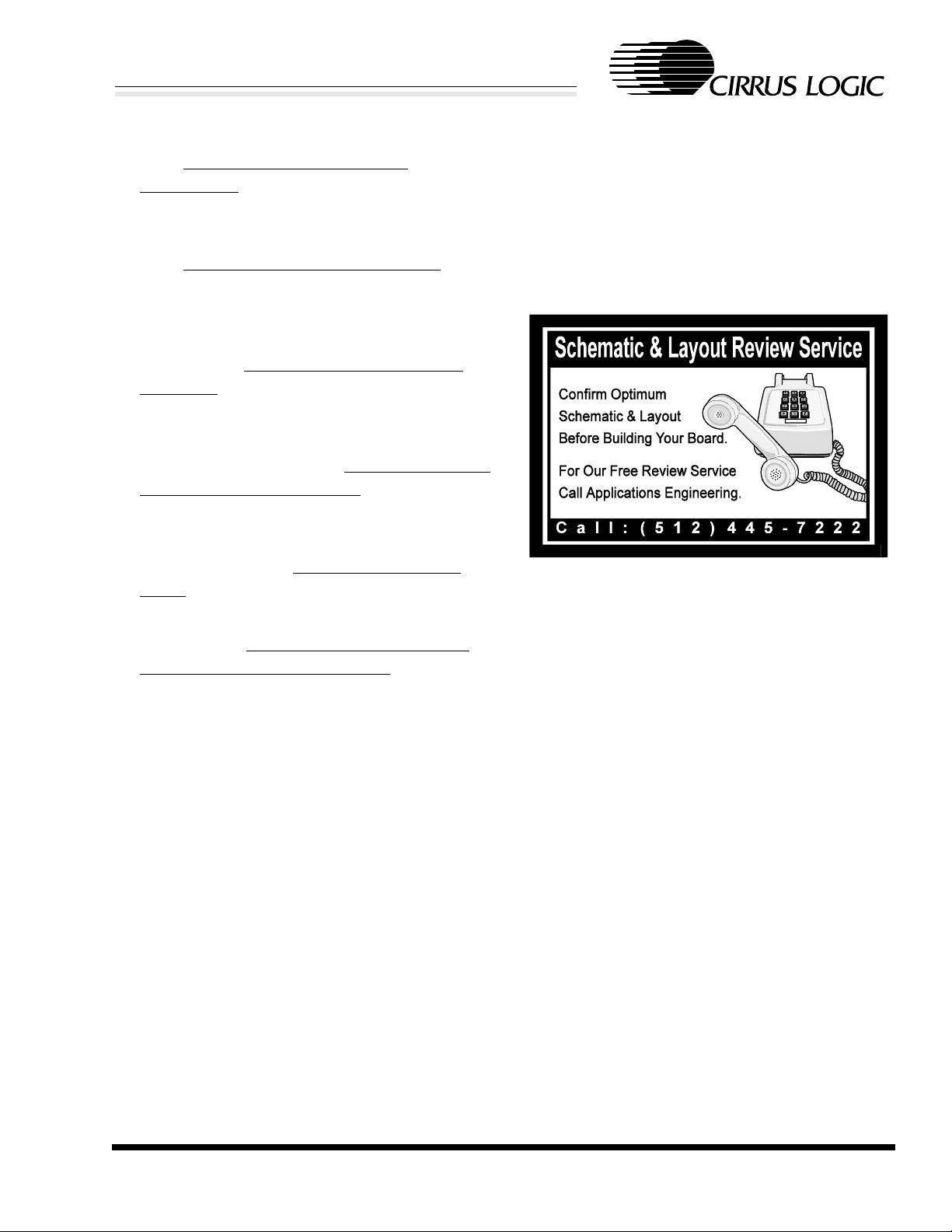
SCHEMATIC DESCRIPTION
Figures 11 through 17 show the schematics for the
CRD4297-1 AMR card. This section will describe
particular pages of the schematic that need to be
discussed.
Figure 11: Block Diagram
The block diagram is an interconnection overview
between schematic pages.
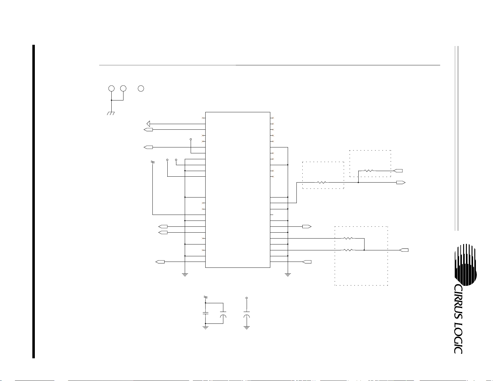
Figure 12: AMR Bus Interface
The +5 V power pin is decoupled through C1 and
supplies power for the SPDIF_OUT circuit. All

CRD4297-1 AMR
CrystalClear™ A C '97 AMR A udio Modem Riser Reference
ground pins are tied to digital ground except for B2,
which is tied to analog ground.
The AC-link, which consists of ASDOUT, ARST#,
ASYNC, ASDIN, and ABITCLK, transfers digital
audio data between the audio codec and the host.
PC_BEEP_BUS routes the motherboard
beep/speaker signal from the motherboard to the
audio subsystem, for use in hearing POST codes
(refer to the Intel Audio/Modem Riser Specification
[2]).
The PRIMARY_DN# signal indicates the presence
or the absence of a primary codec on the mother board. The MSTRCLK is the 24.576 MHz master
clock for the AC ‘97 link. Populate R51 since the
CS4297 is always the primary codec. Populate R50
for CS4297A/99, when they are the secondary c odec.
The CS4297 does not support S/PDIF, R3 is populated so the S/PDIF signal originates from the
AMR bus. For a CS4297A/99 by populating R2 instead of R3, the SPDIF_CODEC signal is directly
routed to the S/PDIF circuit, bypassing the AMR
bus.
Figure 13: Power Supply
The CS4297 requires both a digital +3.3 V and an
analog +5 V supply. The digital power is supplied
from the AMR bus. A separate regulator is recommended for the analog voltage supply to provide
good audio signal quality. A Motorola MC78L05
regulates the +12 V supply from the AMR bus
down to a clean +5 V analog supply. Two packaging options are supported, where U5 is an SO8 surface mount package and U4 is a TO-92 pin-in-hole
package. The -12 V power pin is decoupled
through C73/C74, and supplies power to the headphone circuit.
added next to pins 25 and 26 if the capacitor connected to the output of the power regulator is located far away from the CS4297. All filtering
capacitors of audio signals are NPO-type to ensure
minimal added distortion. Two footprints are provided for the crystal XTAL: a CA-301 pin-in-hole
footprint, Y1, for miniature crystal; and a standard
HC-49U package, Y2. The HC-49U package c an
be bent over and soldered to the card. R47 is a termination resistor in the serial AC-link between the
CS4297 and the AMR bus.
Figure 15: Analog Inputs
The inputs for AUX, VIDEO, CD, and LINE are
passed through a divider circuit that reduces the
voltage by 6 dB to allow connection of line level
sources up to 2 Vrms. The 220 pF capacitors are
provided on Line_In, Mic_In, CD_In, Aux_In,
Video_In, and Internal Modem connection for
EMC suppression. These may be removed if EMC
testing determines they are not required. 1 µF ACcoupling capacitors are used on the Line_In,
Mic_In, CD_In, Aux_In, Video_In, and Internal
Modem circuit to minimize the low frequency rolloff. The internal CD audio connection utilizes a
pseudo-differential interface with CD_GND as the
common return path for both the left and right
channels. Therefore, the input impedance of this
block is half of that of the other inputs.
The modem connection is both a mono input and
output. The output is fed from the CS4297’s
MONO_OUT pin through a divider made of
R22/23. The divider ratio is preset to 0 dB for an
output voltage of 1 Vrms. If a lower output voltage
is desired, the resistors can be replaced with appropriate values, as long as the total load on the output
is kept greater than 10 kΩ. The input is not divided
to accommodate line level sources up to 1 Vrms.
Figure 14: CS4297 AC ‘97 Audio Codec
For the best audio performance, the analog voltage
regulator, an MC78L05, is located near the
CS4297. A 10 µF electrolytic capacitor should be
CIRRUS LOGIC ADVANCED PRODUCT DATABOOK
DS242RD1B1 5
Figure 16: Audio Outputs
The line out is driven directly by the CS4297. The
headphone out amplifier, a Motorola MC1458, is

CRD4297-1 AMR
CrystalClear™ AC '97 AMR Audio Modem Riser Reference
capable of driving stereo headphones with impedances greater than 32 Ω or powered speakers.
R37/38 are added for short-circuit protection. An
optical S/PDIF (IEC 958 consumer) output is also
supported.
Figure 17: Microphone Pre-amp and Bias
A Motorola MC33078D low noise dual op-amp
provides an +18 dB gain stage for the microphone
and buffers the phantom power supply for the mic.
The phantom power is derived from the +5 V analog supply and buffered by U1A to provide a maximum of 4.2 V with no load and a minimum of
2.0 V under a 0.8 mA load on the ring, as required
by the PC 99 System Design Guide, Chapter 17,
Audio Components [5].
Component Selection
Great attention was given to the particular components on the CRD4297-1 AMR board with cost,
performance, and package selection as the most important factors. Listed are some of the guidelines
used in the selection of components:
• no components smaller than 0805 package
• use single package components, no resistor
packs
• right-angled headers for all internal connections to provide sufficient headroom for the
jacks
EMC Components
A number of capacitors and inductors are included
to help the board meet EMC compliance tests, such
as FCC Part 15. Modifying this selection of components without EMC testing could cause EMC compliance failure.
GROUNDING AND LAYOUT
Partitioned Voltage and Ground Planes
The pinout of the CS4297 allows the ground split to
completely separate digital signals on one side and
analog signals on the other. This split is located
very close to the CS4297 so analog and digital
ground return currents originating from the
CS4297 may flow through their respective ground
planes. A bridge is made across the split to maintain the proper reference potential for eac h ground
plane.
The area around the crystal oscillator and the two
XTAL signals is filled with copper on the top and
bottom sides and attached to digital ground. This
ground plane serves to keep noise from coupling
onto these pins. All data converters are highly susceptible to noise on the crystal pins.
A separate chassis ground provides a reference
plane for all of the EMC components. The chassis
ground plane is connected to the analog ground
plane at the external jacks.
• dual footprint for XTAL. Standard H49U with
GND pad and small circular CA-301 pin-inhole package
• Dual footprint for +5 V and +3.3 V regulators.
Surface mount and pin-in-hole package are
supported.
CIRRUS LOGIC ADVANCED PRODUCT DATABOOK
6 DS242RD1B1
CS4297 Layout Notes
Please refer to the CS4297 Data Sheet [3] on how
the area under the chip should be partitioned and
how the bypass capacitors should be placed. Pay
close attention to the suggestions for the bypass capacitors on REFFLT, AFLT1, AFLT2, and the
power supply capacitors. The pinout of the CS4297
is designed to keep digital and analog signals from
crossing when laying out the board.

CRD4297-1 AMR
CrystalClear™ A C '97 AMR A udio Modem Riser Reference
AUDIO PERFORMANCE EVALUATION
Signal Name Connector Maximum Voltage Reference
Designator
Line In Jack 2.341 V
Mic In Jack 0.146 V
Line Out Jack 1.058 V
Speaker Out (8Ω) N/A N/A 0 dB FS(so) N/A
In the above reference designators, the letters in parenthesis designate the full-scale value for that particular I/O. These are used in the tables below to
Microphones Supported Support Comments
3-Pin Phantom Power (power on ring) Yes
2-Pin Dynamic Yes
2-Pin Phantom Power (power on tip)
Full Duplex (A-D-PC-D-A):
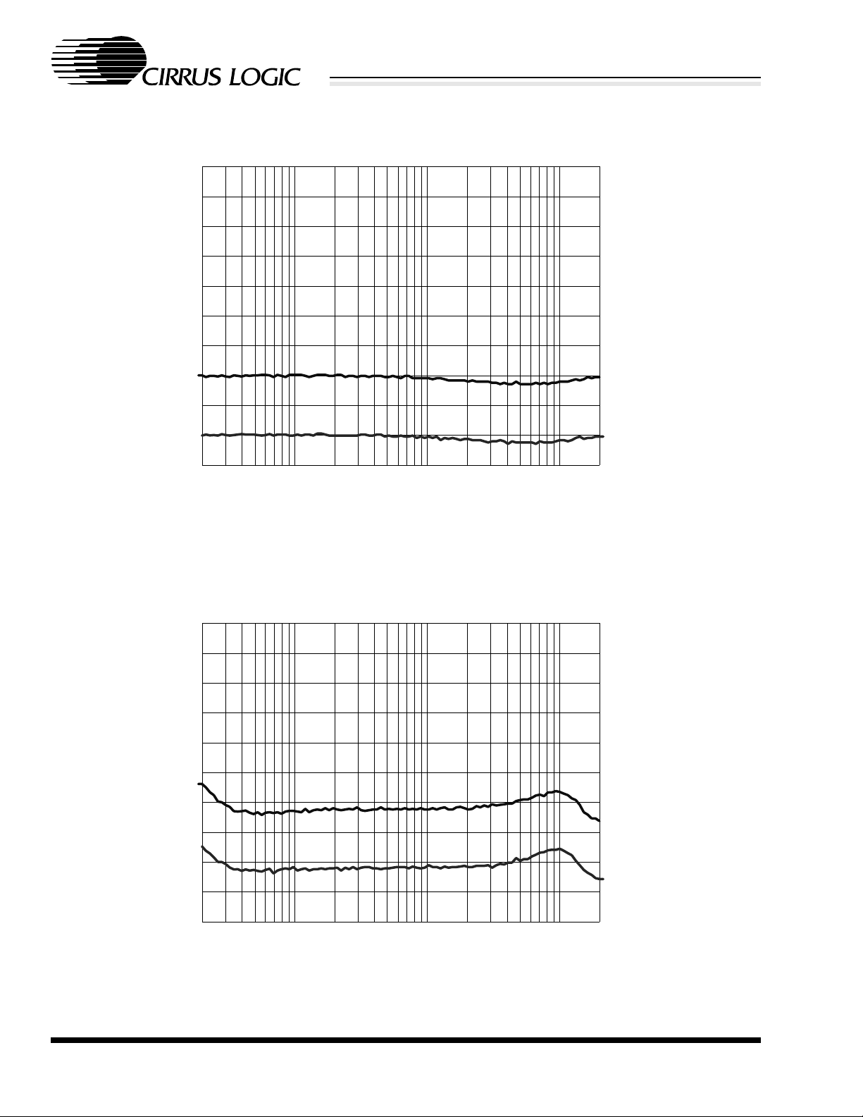
Line In to Line Out Reference Left Right Units Figures
Dynamic Range 83.8 83.8 dB FS A (lo) 97 - 1NXL
THD+N -3 dB FS (li) -81.1 -80.5 dB FS (lo) 97 - 1DXL
Frequency Response Ac = -0.25 dB 20-20k 31-20k Hz 97 - 1MXL
NOTE: TM004: combined test used in lieu of TM002 and TM003
help clarify which full-scale value applies to the
particular measurement. Values referenced to digital numbers on the PC are liste d with the (d) suffix.
RMS
RMS
RMS
0 dB FS (li)
0 dB FS (mi)
0 dB FS (lo) N/A
Imp. (k
Ω)
Analog Mixer (A-A):
Line In to Line Out Reference Left Right Units Figures
Dynamic Range 95.4 95.3 dB FS A (lo) 97 - 1NAL
THD+N -3 dB FS (li) -91.2 -90.6 dB FS (lo) 97 - 1DAL
Frequency Response Ac = -0.1 dB 20-20k 20-20k Hz 97 - 1MAL
Crosstalk f = 10 kHz -66.7 N/A dB FS (lo) 97 - 1CAL
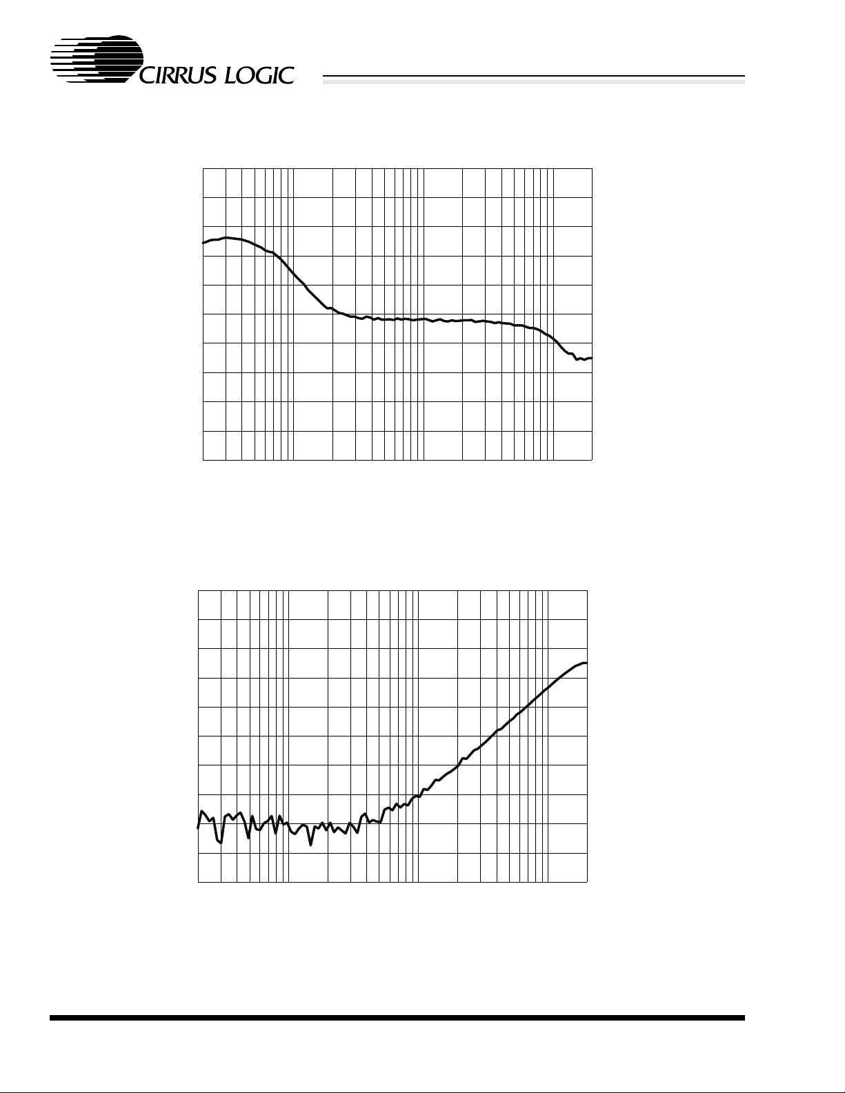
Analog Mixer (A-A):
Mic In to Line Out Reference Left Right Units Figures
Dynamic Range Gain = 0 dB 93.9 N/A dB FS A (lo) 97 - 1NAM
THD+N -3 dB FS (mi) -85.9 N/A dB FS (lo) 97 - 1DAM
Frequency Response Ac = -3 dB 58-15.5k N/A Hz 97 - 1MAM
NOTE: Mic In is Mono
Plots
In the following plots, stereo measurements have
two sets of data per plot and two vertical axes.
Above each vertical axis is a label indicating a
channel that relates to that axis. The data set extends beyond the vertical axis to indicate its association with that axis. Using Figure X as an example,
the top set of data extends beyond the right vertical
axis, which is labeled at the top “RIGHT’, indicating that the top set of data is the right channel and
associated with the right vertical axis. Likewise,
the bottom set of data extendds beyond the left vertical axis which is labeled at the top “LEFT”, indicating that the bottom set of data is the left channel
and associated with the left vertical axis.
CIRRUS LOGIC ADVANCED PRODUCT DATABOOK
DS242RD1B1 7

CrystalClear™ AC '97 AMR Audio Modem Riser Reference
CwGRAPH 0.65 CrystalWare(tm)
CRD4297-1 AMR
3
2
1
0
-1
-2
-3
Amplitude (dB)
-4
-5
-6
-7
20 100 1 k 10 k 20 k
97-1\97-1MXL.ADXLEFT RIGHT
Frequency (Hz)
6
5
4
3
2
1
0
-1
-2
-3
-4
Figure 1. Full Duplex (A-D-PC-D-A): Line In/Out Frequency Response
Amplitude (dB)
CwGRAPH 0.65 CrystalWare(tm)
-60
-65
-70
-75
-80
-85
-90
-95
Dynamic Range (dB FS A)
-100
-105
-110
20 100 1 k 10 k 20 k
97-1\97-1NXL.ADXLEFT RIGHT
Frequency (Hz)
Figure 2. Full Duplex (A-D-PC-D-A): Line In/Out Dynamic Range
-50
-55
-60
-65
-70
-75
-80
-85
-90
-95
-100
Dynamic Range (dB FS A)
CIRRUS LOGIC ADVANCED PRODUCT DATABOOK
8 DS242RD1B1

CRD4297-1 AMR
CrystalClear™ A C '97 AMR A udio Modem Riser Reference
CwGRAPH 0.65 CrystalWare(tm)
-60
-65
-70
-75
-80
-85
-90
THD+N (dB FS)
-95
-100
-105
-110
20 100 1 k 10 k 20 k
97-1\97-1DXL.ADXLEFT RIGHT
Frequency (Hz)
Figure 3. Full Duplex (A-D-PC-D-A): Line In/Out THD+N vs. Frequency
-50
-55
-60
-65
-70
-75
-80
-85
-90
-95
-100
THD+N (dB FS)
CwGRAPH 0.65 CrystalWare(tm)
3
2
1
0
-1
-2
-3
Amplitude (dB)
-4
-5
-6
-7
20 100 1 k 10 k 20 k
97-1\97-1MAL.ADXLEFT RIGHT
Frequency (Hz)
Figure 4. Analog Mixer (A-A): Line In/Out Frequency Response
6
5
4
3
2
1
0
Amplitude (dB)
-1
-2
-3
-4
CIRRUS LOGIC ADVANCED PRODUCT DATABOOK
DS242RD1B1 9
CrystalClear™ AC '97 AMR Audio Modem Riser Reference
CwGRAPH 0.65 CrystalWare(tm)
CRD4297-1 AMR
-60
-65
-70
-75
-80
-85
-90
-95
Dynamic Range (dB FS A)
-100
-105
-110
20 100 1 k 10 k 20 k
97-1\97-1NAL.ADXLEFT RIGHT
Frequency (Hz)
Figure 5. Analog Mixer (A-A): Line In/Out Dynamic Range
-50
-55
-60
-65
-70
-75
-80
-85
-90
-95
-100
Dynamic Range (dB FS A)
CwGRAPH 0.65 CrystalWare(tm)
-60
-65
-70
-75
-80
-85
-90
THD+N (dB FS)
-95
-100
-105
-110
20 100 1 k 10 k 20 k
97-1\97-1DAL.ADXLEFT RIGHT
Frequency (Hz)
Figure 6. Analog Mixer (A-A): Line In/Out THD+N vs. Frequency
-50
-55
-60
-65
-70
-75
-80
-85
-90
-95
-100
THD+N (dB FS)
CIRRUS LOGIC ADVANCED PRODUCT DATABOOK
10 DS242RD1B1

CRD4297-1 AMR
CrystalClear™ A C '97 AMR A udio Modem Riser Reference
CwGRAPH 0.65 CrystalWare(tm)
3
2
1
0
-1
-2
-3
Amplitude (dB)
-4
-5
-6
-7
20 100 1 k 10 k 20 k
97-1\97-1MAM.ADX
Frequency (Hz)
Figure 7. A n alog Mixer ( A-A): Mic In/ Line Out Fr equency Resp onse
CwGRAPH 0.65 CrystalWare(tm)
-60
-65
-70
-75
-80
-85
-90
-95
Dynamic Range (dB FS A)
-100
-105
-110
20 100 1 k 10 k 20 k
97-1\97-1NAM.ADX
Frequency (Hz)
Figure 8. Analog Mixer (A-A): Mic In/Line Out Dynamic Range
CIRRUS LOGIC ADVANCED PRODUCT DATABOOK
DS242RD1B1 11
CrystalClear™ AC '97 AMR Audio Modem Riser Reference
CwGRAPH 0.65 CrystalWare(tm)
CRD4297-1 AMR
-60
-65
-70
-75
-80
-85
-90
THD+N (dB FS)
-95
-100
-105
-110
20 100 1 k 10 k 20 k
97-1\97-1DAM.ADX
Frequency (Hz)
Figure 9. Analog Mixer (A-A): Mic In/Line Out THD+N vs. Frequency
CwGRAPH 0.65 CrystalWare(tm)
-50
-55
-60
-65
-70
-75
-80
Crosstalk (dB)
-85
-90
-95
-100
20 100 1 k 10 k 20 k
97-1\97-1CAL.ADX
Frequency (Hz)
Figure 10. An alog Mixer (A-A): Line In/ Out Crosstalk vs. Freque ncy
CIRRUS LOGIC ADVANCED PRODUCT DATABOOK
12 DS242RD1B1
CRD4297-1 AMR
CrystalClear™ A C '97 AMR A udio Modem Riser Reference
REFERENCES
1) Intel, Audio Codec ‘97 Component
Specification, Revision 2.1,
http://developer.intel.com/pc-supp/
platform/ac97/
2) Intel, Audio/Modem Riser Specification,
Revision 1.01, Sep 10, 1998.
http://developer.intel.com/pcsupp/platform/ac97/INDEX.HTM
3) Cirrus Logic, CS4297 SoundFusion Audio
Codec ‘97 Data Sheet, July 1998.
http://www.cirrus.com/products/overviews/
cs4297.html
4) Steve Harris, Clif Sanchez, Personal Computer
Audio Quality Measurements, Ver 0.5
http://www.cirrus.com/products/papers/
meas/meas.html
5) Intel and Microsoft, PC 99 System Design
Guide
http://www.microsoft.com/hwdev/desguid/
ADDENDUM
• Schematic drawings
• Layout drawings
• Bracket drawing
• Bill of materials
6) M. Montrose. Printed Circuit Board Design
Techniques for EMC Compliance, IEEE Press,
New York: 1996.
CIRRUS LOGIC ADVANCED PRODUCT DATABOOK
DS242RD1B1 13

14 DS242RD1B1
AMR_BUS
CIRRUS LOGIC ADVANCED PRODUCT DATABOOK
AUDIO_IN
AUDIO_IN
PC_BEEP_BUS
PC_BEEP
PC-BEEP-BUS
CD_INL
CD_COM
CD_INR
LINE_IN_L
LINE_IN_R
AUX_INL
AUX_INR
VIDEO_L
VIDEO_R
PHONE_IN
MONO_OUT
PC_BEEP_BUS
AMR_BUS
PC_BEEP
CD_INL
CD_COM
CD_INR
LINE_IN_L
LINE_IN_R
AUX_INL
AUX_INR
VIDEO_L
VIDEO_R
PHONE_IN
MONO_OUT
CS4297
PC_BEEP
CD_INL
CD_COM
CD_INR
LINE_IN_L
LINE_IN_R
AUX_INL
AUX_INR
VIDEO_L
VIDEO_R
PHONE_IN
MONO_OUT
CS4297
MSTRCLK
MSTRCLK
MSTRCLK
MIC1
ARST#
PRIMARY_DN#
ASYNC
ARST#
PRIMARY_DN#
ARST#
PRIMARY_DN#
ASYNC
ABITCLK
ASDOUT
ASDIN
ASDOUT
ABITCLK
ASDIN
ASDIN
ASYNC
ASDOUT
ABITCLK
ALT_LINE_OUT_L
ALT_LINE_OUT_R
S/PDIF_CODEC
SPDIF_CODEC
S/PDIF_CODEC
LINE_OUT_R
LINE_OUT_L
S/PDIF_OUT
LINE_OUT_R
LINE_OUT_L
ALT_LINE_OUT_L
ALT_LINE_OUT_R
SPDIF_OUT
AUDIO_OUT
LINE_OUT_R
LINE_OUT_L
ALT_LINE_OUT_L
ALT_LINE_OUT_R
AUDIO_OUT
CrystalClear™ AC '97 AMR Audio Modem Riser Reference
SPDIF_OUT
POWER
POWER
AUDIO_MICIN
AUDIO_MICIN
MIC1
MIC1
Figure 11. Block Diagram
CRD4297-1 AMR
DS242RD1B1 15
AMR BU
S
populate R2 for
CS4299 board
populate R3 for
CS4297 board
populate R51 if
primary AMR device.
populate R50 if
secondary AMR
device.
DGNDDGND+12VD+3.3VD+5VD
AGND
+3.3V
D
DGNDDGN
D
+5VDCGND-12V
D
KEYKEYKEYKE
Y
P1
AMR CONNECTO
RB1B2B3B4B5B6B7B8B9B10
B11
B12
B13
B14
B15
B16
B17
B18
B19
B20
B21
B22
B23A1A2A3A4A5A6A7A8A9A10
A11
A12
A13
A14
A15
A16
A17
A18
A19
A20
A21
A22
A23
AUDIO_MUTE#
GND
MONO_OUT/PC_BEEP
RSVD
RSVD
PRIMARY_DN#
-12V
GND
+12V
GND
+5VD
GND
RSVD
RSVD
+3.3VD
GND
AC97_SDATA_OUT
AC97_RESET#
AC97_SDATA_IN3
GND
AC97_SDATA_IN2
GND
AC97_MSTRCLK
AUDIO_PWRDN
MONO_PHONE
RSVD
RSVD
RSVD
GND
+5Vdual/+5VSB
USB_OC
GND
USB+
USB-
GND
S/PDIF_IN
GND
+3.3Vdual/+3.3VSB
GND
AC97_SYNC
GND
AC97_SDATA_IN1
GND
AC97_SDATA_IN0
GND
AC97_BITCLK
C2
0.1uF
Z5UR30R20M1HO
LE1M3
TOOLH
OLEM2HO
LE
1
+
C1
10UF
12
+
C3
10UF
12
R50
47
R51
47
ARST
#
ABI
TCLK
ASYNC
ASDINASDOUT
PRIMARY_DN#
MSTRCL
K
S/PDIF_OUT
S/PDIF_CODEC
PC
_BEEP_BUS
CIRRUS LOGIC ADVANCED PRODUCT DATABOOK
CRD4297-1 AMR
CrystalClear™ A C '97 AMR A udio Modem Riser Reference
Figure 12. AMR Bus

16 DS242RD1B1
CIRRUS LOGIC ADVANCED PRODUCT DATABOOK
POWER SUPPLIES
GND2GND3
GND1
VOUTVIN
AGND
MC78L05ACD
36
2
18
U4
MC78L05
AGNDAGND
Do not populate U5
+12VD
L2
31@100MHz
100uF
C70
+12VA
U5
+
5 4
NC2 NC1
7
GND4
3 1
IN OUT
C71
0.1uF
Z5U
Connect AGND to DGND with a 50 mil trace near the 4297
Connect CGND to DGND with a 50 mil trace near the finger
edge of the board.
SURFACE MOUNT
POPULATION
OPTION
+5VA
PIN IN HOLE
POPULATION
+
OPTION
C72
10UF
-12VD
L1
31@100MHz
-12VA
C73
100uF
AGND
C74
0.1uF
Z5U
CrystalClear™ AC '97 AMR Audio Modem Riser Reference
CRD4297-1 AMR
Figure 13. Power Supplies

DS242RD1B1 17
y
C62, C63 and
3
CRD4297-1 AMR
CrystalClear™ A C '97 AMR A udio Modem Riser Reference
+3.3VD
CIRRUS LOGIC ADVANCED PRODUCT DATABOOK
DO NOT
POPULATE R45
MSTRCLK
C64
1.0uF
C51
0.1uF
Z5U
R45 0
C65
0.1uF
Z5U
+5VA
C52
0.1uF
Z5U
AGNDDGND
layout Y1 on top
of Y2 -- populate
onl
one XTAL
Y1
24.576 MHz
1 2
Y2
C60
22pF
DGND
C66
1.0uF
C53
0.1uF
C67
0.1uF
Z5U
C61
22pF
C54
0.1uF
Z5U
ASDIN
ASYNC
ARST#
PC_BEEP
PHONE_IN
AUX_INL
AUX_INR
VIDEO_L
VIDEO_R
CD_INL
CD_COM
CD_INR
MIC1
LINE_IN_L
LINE_IN_R
C68
390pF
NPO
+3.3VD
C69
390pF
NPO
+5VA
U3
25 26
AVdd1 AVss1
38
AVdd2
1
DVdd1
9
DVdd2
2
XTL_IN
3
XTL_OUT
8
SDATA_IN
10
SYNC
11
RESET#
12
PC_BEEP
13
PHONE
14
AUX_L
15
AUX_R
16
VIDEO_L
17
VIDEO_R
18
CD_L
19
CD_GND
20
CD_R
21
MIC1
22
MIC2
23
LINE_IN_L
24
LINE_IN_R
27
REFFLT
28
Vrefout
29
AFLT1
30 48
AFLT2 S/PDIF_OUT
CS4297
AVss2
DVss1
DVss2
BIT_CLK
SDATA_OUT
LINE_OUT_L
LINE_OUT_R
MONO_OUT
ALT_LINE_OUT_L
ALT_LINE_OUT_R
NC1
FLT3D
FLTI
FLTO
NC5
NC6
NC7
ID0#
ID1#
EAPD
C55
680pF
NPO
AGND
42
4
7
6
5
35
36
37
39
41
31
32
33
34
40
43
44
45
46
47
R47 47
C62
NPO
R48 0
C56
680pF
NPO
1000pF
AGNDDGND
C63
0.01uF
AGND
C57
680pF
NPO
X7R
C58
680pF
NPO
ABITCLK
ASDOUT
LINE_OUT_L
LINE_OUT_R
MONO_OUT
ALT_LINE_OUT_L
ALT_LINE_OUT_R
Do not populate
R48 for CS4297.
Polpulate C62,
C63 and R48 for
CS4299
PRIMARY_DN#
S/PDIF_CODEC
C59
680pF
NPO
AGND
Figure 14. CS4297

18 DS242RD1B1
VIDEO IN
L
GND
GND
R
AUX IN
CD IN
L
GNDGN
D
R
Connect CGND to
AGND at the
jack
LINE IN
MONO OUT
PHONE IN
GND
GND
INTERNAL MODEM CONNECTION
PC SPEAKER IN
L
GND
GND
R
AGND
AGND
AGND
AGNDAGN
D
AGN
D
AGNDCGNDAGN
D
AGND
AGND
AGND
AGND
AGND
AGND
AGND
AGND
AGND
R106.8KR116.8KR5
6.8KR6
6.8
K
R14
6.8
K
R15
6.8KR18
6.8KR19
6.8KR7
6.8KR4
6.8KR9
6.8
K
R8
6.8
K
R12
3.4
K
R13
3.4KR166.8KR176.8KR206.8KR216.8KR23
47K
R24
47K
R22
0
C26
0.1uF
Z5UC10
220pF
R31
47KC11
220pF
C12220pF
C19220pF
C21220pF
C22220pFC23
220pF
C24220pFC16
220pF
C17220pFC18
220pFJ14X1HD
R-AU1234J54X1HD
R-AU12
3
4
J2
4X1HD
R-AU1234J34X1HD
R-AU1234J4PHONO-1/84
3521C4
1uFX7RC81uFX7RC151uFX7R
C251uF
X7RC281uF
X7R
C291u
F
X7RC51uFX7RC91uFX7R
C141u
F
X7RC201uFX7
R
C131u
F
X7
R
VIDEO_R
VIDE
O_L
AUX_INRAUX
_INL
CD_INR
CD_INL
CD_C
OM
LINE_IN_R
LINE_IN_L
MONO_OUT
PHONE_IN
PC
_BEEP
PC-B
EEP-BUS
CIRRUS LOGIC ADVANCED PRODUCT DATABOOK
CrystalClear™ AC '97 AMR Audio Modem Riser Reference
CRD4297-1 AMR
Figure 15. Audio In

DS242RD1B1 19
HEADPHONE
JACK
LINE OUT
JACK
Connect CGND to
AGND at the
jack
Connect CGND to
AGND at the
jack
Digital Outp
ut
CGN
D
AGND
CGNDAGND
DGND
DGND
DGND+5VDAGND
+12VA
+12VA
AGND
AGND
-12VA
-12VA
R37101/4
W
R3810
1/4WJ1
0
TO
TX-173
1
23456
R49
8.2KU2AMC14
58
321U2B
MC14
58
567
R3527
K
C4122pFR36
56KR43100KR44
100KC46
10UF
12C47
10UF
1
2
C4010UF
1
2
C4210UF12
C44
22
0pF
C45
22
0pF
C48220pFC49
220pF
C4322pF
C50
0.1uF
Z5UR3927K
R4
0
56KJ9
PHONO-1
/84352
1
J7
PHONO-1
/8
4
3
521ALT_LINE_OUT_L
ALT_L
INE_OUT_R
LINE_OU
T_R
LINE_
OUT_L
SPDIF_O
UT
CIRRUS LOGIC ADVANCED PRODUCT DATABOOK
CRD4297-1 AMR
CrystalClear™ A C '97 AMR A udio Modem Riser Reference
Figure 16. Audio Out

20 DS242RD1B1
CIRRUS LOGIC ADVANCED PRODUCT DATABOOK
R26
68K
AGND
R28
100K
+5VA
+5VA
U1A
84
MC33078D
3
+
1
2
-
AGND
12
+
AGND
R29 47K
C31
10UF
AGND
R25
47K
R27
47K
CrystalClear™ AC '97 AMR Audio Modem Riser Reference
J6
PHONO-1/8
Connect CGND
to the jack
CGND
C35
220pF
R32 2.7K
C36
220pF
C33 0.068 uF
X7R
place close to
pins 8 and 4
+5VA
AGND
C30
0.1uF
Z5U
R33 6.8K
12
+
C37
10UF
AGND
4
3
5
2
1
AGND
+5VA
84
5
+
6
-
AGND
C38 220pF
R34 47K
U1B
MC33078D
7
C34 1uF
X7R
MIC1
CRD4297-1 AMR
Figure 17. Mic Pre-Amp

DS242RD1B1 21
CIRRUS LOGIC ADVANCED PRODUCT DATABOOK
CRD4297-1 AMR
CrystalClear™ A C '97 AMR A udio Modem Riser Reference
Figure 18. Assembly Drawing

22 DS242RD1B1
CIRRUS LOGIC ADVANCED PRODUCT DATABOOK
CrystalClear™ AC '97 AMR Audio Modem Riser Reference
Figure 19. Top Layer
CRD4297-1 AMR

DS242RD1B1 23
CIRRUS LOGIC ADVANCED PRODUCT DATABOOK
CRD4297-1 AMR
CrystalClear™ A C '97 AMR A udio Modem Riser Reference
Figure 20. Bottom Layer

24 DS242RD1B1
CIRRUS LOGIC ADVANCED PRODUCT DATABOOK
CrystalClear™ AC '97 AMR Audio Modem Riser Reference
Figure 21. Bracket Drawing
CRD4297-1 AMR
25 DS242RD1B1
BILL OF MATERIALS
CRD4297-AMR
Item Qty Reference Value Type PCB-Footprint Mnfr Part Number Description
1 9 C1,C3,C31,C37,C40,C42,
2 12 C2,C26,C30,C50,C51,C52,
3 12 C4,C5,C8,C9,C13,C14,C15,
CIRRUS LOGIC ADVANCED PRODUCT DATABOOK
4 18 C10,C11,C12,C16,C17,C18,
5 1 C33 0.068 uF X7R C S N_0805 KEMET C0805C683K5RAC CAP, 0805, X7R, 68000pF, 10%, 50V
6 2 C41,C43 22pF COG SMT_0805 C0805C220GAC CERM CAP,22pF,5%,50V,COG
7 5 C55,C56,C57,C58,C59 680pF NPO SMT_0805 KEMET C0805C681J5GAC CERM CAP, 680pF, 5%, 50V,COG
8 2 C60,C61 22pF COG CC0805 CAP,22pF,SO,0805,5%,50V,COG
9 2 C64,C66 1.0uF Y5V SMT_1206 MURATA GRM42-
10 2 C68,C69 390pF NPO SMT_0805 KEMET C0805C391J5GAC CERM CAP,390pF, 5%, 50V,COG
11 2 C70,C73 100uF ELECT PIH PANASONIC ECA-1CM101 ALUM ELECT, 100uF,20%,16V,POL
12 4 J1,J2,J3,J5 4X1HDR-AU CONN CON_MLX_70553 MOLEX 70553-0003 HDR, 4X1, 0.025" PIN, 0.1" CTR, 15u" AU
13 4 J4,J6,J7,J9 PHONO-1/8 CONN CON_STEREO_LZR LZR ELEC-
14 1 J 10 TOTX-173 CONN TOTX173 TOSHIBA TOTX173 OPTICAL TOSLINK TRANSMITTER
15 2 L1,L2 31@100MHz FERRITE IND_FB1206 TDK HF50ACB321611-T IND, FBEAD, 1206, 31@100MHz, 25%
16 2 M1,M2 HOLE
17 1 M3 TOOLHOLE TOOLHOLE
18 1 P1 AMR CON-
19 2 R 3,R22 0 RES RES_0805 PHILIPS 9C08052A0R00J RES, SO, 0805, 0.5%, 1/10W, METAL FILM
20 17 R4,R5,R6,R7,R8,R9,R10,
21 2 R 12,R13 3.4K RES RES_0805 PHILIPS 9C08052A3401F RES, SO, 0805, 3.4K, 1%, 1/10W, METAL FILM
22 7 R 23,R24,R25,R27,R29,
23 1 R 26 68K RES RES_0805 PHILIPS 9C08052A6802J RES, SO, 0805, 68K, 5%, 1/10W, METAL FILM
24 3 R 28,R43,R44 100K RES RES_0805 PHILIPS 9C08052A1003J RES, SO, 0805, 100K, 5%, 1/10W, METAL FILM
25 1 R 32 2.7K RES RES_0805 PHILIPS 9C08052A2701J RES, SO, 0805, 2.7K, 5%, 1/10W, METAL FILM
26 2 R35,R39 27K RES RES_0805 PHILIPS 9C08052A2702J RES,27K,SO,0805,5%,1/10W,METAL FILM
27 2 R36,R40 56K RES RES_0805 PHILIPS 9C08052A5602J RES,56K,SO,0805,5%,1/10W,METAL FILM
28 2 R 37,R38 10 RES RES_1206 PHILIPS 9C12063A10R0J RES, SO, 1206, 10, 5%, 1/4W, METAL FILM
29 2 R47,R51 47 RES RES_0805 PHILIPS 9C08052A47R0J RES, SO, 0805, 47, 5%, 1/10W, METAL FILM
C46,C47,C72
C53,C54,C65,C67,C71,
C74
C20,C25,C28,C29,C34
C19,C21,C22,C23,C24,
C35,C36,C38,C44,C45,
C48,C49
R11,R14,R15,R16,R17,
R18,R19,R20,R21,R33
R31,R34
10UF ELELCT ALUM/10UF/16P PANASONIC ECA-1CM100 ALUM ELE CT,10uF,20%,16V,POL
0.1uF Z5U CSN_0805 KEMET C0805C104M5UAC CAP, 0805, Z5U, .1uF, 20%, 50V
1uF X7R CSN_1206 VENKEL C1206X7R500-
105KNE
220pF COG SMT_0805 KEMET C0805C221J5GAC CERM CAP,220pF,5%,50V,COG
6Y5V105Z016BL
SJ372 CONN, 1/8" DOUBLE SW. STEREO PHONE
TRONICS
AMR5V-46
NECTOR
6.8K RES RES_0805 PHILIPS 9C08052A6801F RES, SO, 0805, 6.8K, 1%, 1/10W, METAL FILM
47K RES RES_0805 PHILIPS 9C08052A4702J RES, SO, 0805, 47K, 5%, 1/10W, METAL FILM
CAP, 1206, X7R, 1uF, 10%, 25V
CERM CAP,1.0UF,25V,Y5V
JACK
CrystalClear™ AC '97 AMR Audio Modem Riser Reference
CRD4297-1 AMR

DS242RD1B1 26
Item Qty Reference Value Type PCB-Footprint Mnfr Part Number Description
30 1 R49 8.2K RES RES_1206 Philips 9C12063A820J RES,8.2k,SM1206,5%,1/4W
31 1 U 1 MC33078D OP AMP SO8 MOTOROLA MC33078D IC, SO, SOIC8, 33078, DUAL OP AMP
32 1 U2 MC1458 SO8 SO8 MOTOROLA MC1458 DUAL HEADPHONE AMP
33 1 U3 CS4297 CODEC QFP48_7X7 CRYSTAL
34 1 U4 MC78L05 VREG TO-92 MOTOROLA MC78L05AC 5V POS.VOLT.REG., 100ma
35 1 Y1 24.576 MHz PAR RES, FUND XTL_CA-301 E PSON CA-301_24.576M-C X TL, 24.576MHz, FUND, PAR RES
DO NOT POPULATE
Item Qty Reference Value Type PCB-Footprint Mnfr Part Number Description
1 1 C63 0.01uF CAP CSN_0805 KEMET C0805C103K5RAC CERM CAP, .01uF, 10%, 50V,X7R
CIRRUS LOGIC ADVANCED PRODUCT DATABOOK
2 1 C62 1000pF CAP SMT_0805 KEMET C0805C102J5GAC CERM CAP, 1000pF, 5%, 50V,COG
3 1 R50 47 RES RES_0805 PHILIPS 9C08052A47R0J RES, SO, 0805, 47, 5%, 1/10W, METAL FILM
4 3 R2,R45,R48 0 RES RES_0805 PHILIPS 9C08052A0R00J RES, SO, 0805, 0, 5%, 1/10W, METAL FILM
5 1 Y2 24.576 MHz XTALHC49PAD EPSON CRYSTAL, 24.576MHz, H49-US TYPE, Fund
6 1 U5 MC78L05ACD VREG SO8 MOTOROLA MC78L05ACD 5V POS. VOLT. REG., 100ma
SEMICOND.
CS4279 IC, SO, AC ’97 2.0 SERIAL CODEC w/ SRC
Mode Par Res
CRD4297-1 AMR
CrystalClear™ AC '97 AMR A udio Modem Riser Reference

• Notes •

 Loading...