

Page 1

CRD4610-1
Advanced Product Databook
FEATURES
■ PCI Audio Accelerator card designed to meet AC
’97 specifications
■ 4-layer single sided planar example board
■ CS4610 SoundFusion™ PCI Audio Accelerator
■ CS4297 SoundFusion™ Audio Codec '97
■ Complete suite of Analog I/O connections:
— Line In, Line Out, Mic In, Headphone or Headset con-
nection, Modem audio connection, CD Audio In, Video
In, Aux In, and PC Speaker In
■ Joystick/MIDI Interface
■ Meets or exceeds Microsoft’s
both required and advanced, audio performance
requirements.
ORDERING INFO
CRD4610-1
®
PC’97 and PC’98 ,
CrystalClear™
AC '97 Motherboard
Reference Design
DESCRIPTION
The CRD4610-1 showcases Cirrus Logic’s Cystal
Audio AC '97 motherboard solution using the
CS4610 SoundFusion Audio Accelerator and the
CS4297 SoundFusion Audio Codec '97. This design illustrates a single sided motherboard
implementation on a PCI adapter card. Using the
Mic In, Line Out and Line In analog connectors
only, the combined motherboard footprint is approximately 3.1 sq. in. This area is outlined around
the CS4610 and the CS4297. The card includes
other optional analog inputs and outputs, as well.
Volume control buttons are also included to demonstrate the hardware master volume control.
CIRRUS LOGIC ADVANCED PRODUCT DATABOOK
NOV ‘97 DS241RD1C1
Copyright Cirrus Logic, I nc. 1997
(All Rights Reserv ed)
Page 2

CRD4610-1
CrystalCle ar™ AC '97 Motherboard Refe renc e Design
GENERAL INFORMATION
Today’s multimedia applications demand high
quality PC a udio an d many audi o connec tions. To
®
meet this demand Intel
defined the AC ‘97 (Audio
Codec ‘97) specification that defines a two chip audio solution [1]. The idea behind the two-chip solution is to have a separate audio controller chip
connected to the PCI bus to accelerate increasingly
popular audio p rocessi ng func tion s such as Aure al
TM
A3D
and Dolby
, DirectSound 3DTM, wavetable synthesis,
®
Digital (AC-3®) decoding. A separa te
audio codec is conne cted to th e control ler for ana log mixing and data conversion. Audio data is
transferred be twe e n the co ntr oll er ch ip an d the audio codec through a standard digital interface
called an AC Link at a 48 kHz frame rate. For more
information on AC ‘97 and the AC Link, please
consult the AC ‘9 7 specificatio n [1].
The adv antage of a two chip a udio solu tion is that
the analog section of a system can be completely
separated from the noisy digital envi ronment of a
personal compu ter. A digital link is all that is required to connec t the audio codec t o the PCI busbased AC’97 controller. This allows the audio section to reach the required signal to noise ratio of
~90 dB while making t he layout an d placeme nt of
the audio section easier to impleme nt.
The CRD4610-1 demonstrates Cirrus’ two-chip solution using t he CS4610 SoundFus ion PCI Audio
Accelerator and the CS4297 SoundFusion Audio
Codec. These two integrated circuits demonstrate
Cirrus’ powerful DSP cont roller and unsurpassed
CrystalClear audio quality in a single PCI add-in
card reference desi gn.
REFERENCE DESIGN FEATURES
The reference design ill ustrates a typ ical four-lay er, single side d mot herbo ard layo ut. T he re fer ence
design card is sectioned into th ree main parts: t he
CS4610 PCI Audio Accelerator section, the
CS4297 Audio Codec ‘97 section, and the Optional
Extended Anal og I/O section.
CS4610 PCI Audio Accelerator Section
The area aro und the CS 4610 in cludes th e required
bypass capacitors, PLL power supply filter components, an EEPROM, the components for the joystick connection and a buffer circuit for the external
MIDI connec tion. The layou t of this secti on complies with the PCI specific ation versio n 2.1 [2] for
add-in cards. Please refer to the Schematic and
Layout sections of this document for more information. For more information on the CS4610, refer
to the CS4610 Data Sheet [3]. The required area for
this particular layout is 1.97 sq. in.
External EEPROM
The CS4610 EE PROM c onta ins the requ ired Sub system Vendor ID and Subsystem ID values as well
as two configura tion regi sters which con figure the
software driver of the CS4610 to operate in AC ‘97
link mode. Th e CS4610 currently requir es 7 data
bytes in the EEPR OM for configurat ion. The PCI
Special Interest Group assigns manufacturers a
Subsystem Vendor ID. To meet WHQL
dards, the Subsystem ID must be a non-zero va lue.
Please call Cirrus Logic PC Products Crystal Audio
Division at (512) 445-7222 to have a Subsystem ID
assigned to a particu la r proj ect.
If the CS4610 is im plemented on a mother boa rd,
an external EEPROM is not required for proper operation. A host-load procedure may be used for
configuration in this case. However, silicon revisions rev. C and prior m ust use an EEPROM if a
unique Subsystem ID is required. This is due to an
errata which causes the upper byte of the subsystem
vendor ID to be duplicated in the subsystem ID
field during host load to the SSVID register.
It is recomme nded that a n EEPROM be used during system de velopment to allo w debug and configuration changes without having to modify BIOS
code. If host load will be used in producti on, the
EEPROM circuit ry can be left unpopul ated.
™ stan-
CIRRUS LOGIC ADVANCED PRODUCT DATABOOK
2 DS241RD1C1
Page 3

CRD4610-1
CrystalClear™ AC '97 Motherboard Reference Design
For information regarding the programming and
timing of th e EEPR OM, refer to t he CS4610 Data
Sheet [3].
CS4297 Audio Codec ‘97 Section
This section con tains the compone nts for the Mic
In, Line In, and Line Out audio connections. It also
includes a 24.576 MHz crystal that acts as the mas-
ter clock in an AC ‘97 co nfiguration. The capaci tors required for the CS42 97 and their placement
are discussed in the CS4297 Data She et. Refer to
the Grounding and Layout section of the data sheet
for the recommended routing the audio section [4].
The require d area for thi s particular layout is 1.08
sq. in.
Optional Extended Analog I/O Section
The CS4297 has many ana log inputs and outputs
that may or may not be used depending on the system’s appli cat ion. Un used in puts shou ld be t ied to
Vrefout (pin 28) o r capa citi vely c oup led to the an alog ground plane. The optional section contains
the compo nen ts for a he adpho ne amp lifie r a nd an other microphone amplifier for the MIC2 input.
This section also contains a popul ation option for
headphones or head se t operation on the 1/8 " ext ernal jack. Th e referenc e card ship s with hea dphone
operation enabled. To enable headset operation,
R24 and R26 should be removed and one of the resistors placed in the space for R25. This will enable
the microphone 2 input on the tip connection of the
external jac k and the right head phone channel on
the ring co nne ction of the external jack.
The Modem Audio, CD ROM, Video In, Aux in,
and Spk In headers a re also part of the Extended
Analog I/O section. Each header has a few resistor
packs a nd capacito rs associated with it. The header
and its associ ated compo nents may or may not be
necessary depending on the audio inputs implemented.
Audio Inputs and Outputs
The entire se t of the CS4297 ’s analog I/O is re presented on the refe rence design card through internal headers a nd external connectors:
-Line Out
-Mic In
-Line In
- CD ROM In
- Modem audio connection
- Headphone Out or Headset connection
- Aux In
- Video In
- PC Speaker
Five external 1/8" jacks and six internal header
connections are used for analog inputs and outputs.
The modem audio connection and the line out connection have an internal header and an external 1/8"
jack conne ction. When a pl ug is inserted in to the
external jac k for the modem audio or the line out
connections, the correspondi ng internal conn ector
is disabled.
The line ou t, line in and microphone in circuits are
included in the area outlined around the CS4297
codec. The other analog connections are considered to be part of the optional extended analog I/O.
Line Out
The Line Out connection can either be made
through the exte rna l 1/8" jack or t he int e rnal 4- pin
(0.1 inch center) header. If the 1/8" jack is used the
internal 4 p in connecto r is disabled. The Line Out
output can only drive input impedances greater
than 10 kΩ.
• Maximum outp ut l eve l: 1 Vrms
CIRRUS LOGIC ADVANCED PRODUCT DATABOOK
DS241RD1C1 3
Page 4

CRD4610-1
CrystalCle ar™ AC '97 Motherboard Refe renc e Design
Mic In
The Microphone In 1/8" jack provides an input to a
microphone preamplifier circuit that provides
17 dB of gain.
• Maximum input level:
- Microphone Boost enabled: 12.7 mV
- Microphone Boost di sabled: 127 mV
• Supports 3-pin phantom power and dynamic
microphones
• Microphone power is provided on the ring con-
nection of th e 1/8" stereo jack
Line In
The Line In 1/8" jack provides an input to the Line
In pins of the CS4297 .
• Maximum input level: 2 Vrms
CD ROM In
The CD ROM input header is a 4 p in (0.08 inch
center) shrouded connector that fits most CD ROM
audio ad apter cabl es .
• Maximum input level: 2 Vrms
• Differential input using the CD common pin as
the ground
Modem Audio Connection
The modem audio connection can either be m ade
through the e xter na l 1/8" j ack or the i nter na l 4-pin
(0.1 inch center) header. These connectors have
both an input and an output on them.
External 1/8" jack:
• Ring connection: Mono inp ut
- Maximum input level: 1 Vr ms
• Tip connection: Mono output
- Maximum ou tput level: 0.7 Vrms
Headphone Out or Headset
An external 1/8" ja ck is provided for a hea dphone
or headset co nne ction. The ca rd com es c onf igured
for headphone operation with the selection being
made by a 0 Ω resistor population option. The
headphone option is selected by populating R24
and R26 and not populating R25. The headse t option is selected when R25 is populated and R24 and
R26 are not populated.
Headphone output option:
• Capable of driving low impedance loads such
as 32 Ω headphones
• Maximum outp ut l eve l: 1.4 Vrms
Headset option:
Ring connecti on: Right headphone output
• Maximum outp ut l eve l: 1.4 Vrms
Tip connection: Microphone 2 input
• Maximum input level:
- Microphone Boost enable d: 12 . 7 mV
- Microphone Boost disabled: 127 m V
• Microphone power i s provided o n the tip con nection. This setup supports phantom power
mics only (not dynamic mics)
Aux In
• Internal 4 pin hea der (0.1 inch cen te r )
• Maximum input level: 2 Vr m s
Video In
• Internal 4 pin hea der (0.1 inch cen te r )
• Maximum input level: 2 Vr m s
PC Speaker
• Internal 2 pin hea der (0.1 inch cen te r )
• Mono input for the internal PC speaker output
CIRRUS LOGIC ADVANCED PRODUCT DATABOOK
4 DS241RD1C1
Page 5

CRD4610-1
CrystalClear™ AC '97 Motherboard Reference Design
Other Reference Card Features
Other referenc e card fea tures tha t are not ass ociat ed with the other secti ons are the e xternal vol ume
control buttons, the joystick/ M IDI connection, and
the power regulators.
Volume Control Buttons
The volume control buttons are connected to the
CS4610 and ac t as a master volume co ntrol. The
four-pin header can be populated to provide a cable
connectio n for volu me con trol but tons that can be
placed e lsew he re in t he s yst em. Th ere is a volum e
up button and a volume down button. Pressing both
buttons at the same time enables the mute/unmmute function .
Joystick/MIDI connection
The DB-15 connector allows a joystick or an external MIDI device to be connected to the CS4610. In
the AC’ 97 conf igurati on, the C S4610 ha ndles the
joystick operation. The external connection can
also take MIDI data from a n external source to the
CS4610. A buffer circuit allows the MIDIOUT pin
of the CS4610 to drive an external M IDI input.
Power Regulators
There are t wo powe r regula tors o n the bo ard. One
is a Linear Technologies LT117CST-3.3 voltage
regulator that derives the +3.3 V supply for the
CS4610 and the CS4297 from the +5 V on the PCI
bus. This regulator is unnecessary on mother
boards with a +3.3 V supply. The regulator was
used in this reference design because the +3.3 V
PCI bus power pins are not guaranteed to be on the
PCI bus connector. The card is also designed to be
used in a 5 V PCI Connector [2].
A Motorola MC78M05CDT regulates the PCI
+12 V supply down to provide a clean +5 V analog
supply for the operational amplifiers and the
CS4297. A power regulator is recommended for
the analog voltage supply to provide good audio
signal quality. The MC78M05CDT regulator can
provide up to 500 mA of current with adequate
heat-sinking, which is enough power for the
CS4297 and the three audio op-amps. The
MC78L05 power regulators do not provide enough
current to power the same devices, and are not recommended for use with the CS42 97.
SCHEMATIC DESCRIPTION
Figures 1 through 8 show the schematics for the
CRD4610-1 card. This section will describe particular pages of the schematic that need to be discussed.
Figure 7 : CD Audio Input
C5 and C6 a re used in pa rallel to ma ke a 2 µF capacitor on th e CD Co mmon li ne becau se th e input
impedance on tha t li ne is half of what is on the CD
In Right and CD In Left. A 2 µF capacitor could be
used, but m any of t he 2 µF ca pacitors tested ha ve
shown distortion problems.
Figure 3 : CS4297
A 10 µF electrolytic capacitor should be added
next to pins 25 and 26 if the capacitor connected to
the output of the power regulator is located far
away from the CS429 7. For the best aud io perfor mance, the an alog voltage re gulator should be located near th e C S429 7. R1 and R2 a re te rmin at ion
resistors in the serial AC link be t ween the CS4297
and the CS4610. NPO-type capacitors should be
used on all lo ading capacitors of a udio signals to
ensure minimal a dded distortion.
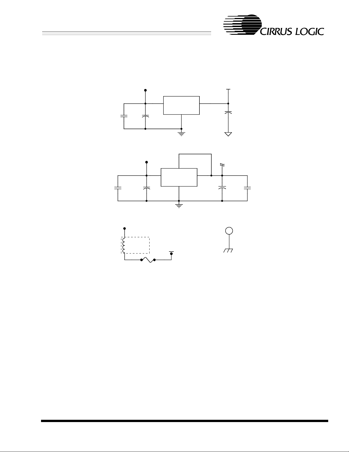
Figure 2 : CS4610
The 0.1 µF capa ci tors connec te d to th e pow er pins
of the CS4610 should be as close as possible to the
chip. The inductor L6 is used to f ilter the power
supply for the in ternal PLL cir cuit. R7 can be removed from a production design, and pin 51 can be
connected directly to digital ground. R3 and R4 are
terminatio n resist ors in the ser ial AC l ink be tween
the CS4297 and the CS4610.
CIRRUS LOGIC ADVANCED PRODUCT DATABOOK
DS241RD1C1 5
Page 6

CRD4610-1
CrystalCle ar™ AC '97 Motherboard Refe renc e Design
Figure 4 : Line Input
Two parallel 1 µF capacitors are used on the line in
circuit to dec rease the low freque ncy corner since
this input is usually used for high signal quality input. A 2 µF capacitor c ould be used , but 2 µF surface mount capacitors are often not high quality
capacitors and can add distortion to audio signals.
Figure 6 : Headphone or Headset
A resistor popula tion optio n is incl uded to ch oose
between a hea dphone or headset connecti on. The
headset connection incorporates the right headphone and MIC2 on one external jack.
Figure 14 : MIDI and Joystick Connection
A buffer driver circuit is use d on the MIDI out put
pin to provide the necessary drive for MIDI devices
connected through a long cable. This circuit can be
removed, and R28 populated to by pass the buffer
driver circuit if it is unnecessary.
Figure 15 : PCI Bus Connection
The PCI 2.1 specification requires that each unused
+3.3 V power pin should be connected with an average of 0.01 µF capacitor [2]. Two 0.1 µF capacitors in parallel provide the required capacitance for
the power pins.
EMC Components
on trace lengths that are not imposed on motherboard designs. These trace length limits for add-in
cards are as follows:
• Maximum trace length for 32-bit signals on 32bit and 64-bit ca rds is 1. 5 inches.
• Maximum trace lengths for signals on th e 64bit extension are 2 inch es .
• Trace length for the PCI CLK signal is 2.5 inches ± 0.1 inch.
• The PCI CLK si gna l must drive only one load.
Please refer to the PCI 2.1 Specification Section
4.3.6 for information on routing PCI bus signals on
a motherboard [2 ].
Partitioned Voltage and Ground Planes
The CRD4610-1 is partitioned into a digital and analog section. Correspondingly, the voltage and
ground planes are partitioned to keep digital and
analog ground currents from crossing. Ground currents from digi tal s igna ls are inhere ntly noisy with
respect to analog signals and should be isolated
from the audio se ction. Th e first ru le in lay ing out
mixed signal PCBs is to keep all digital signals
over the digital ground plane and all analog signals
over the analog ground plane. When digital and analog signals cross pl anes, they introduce noise into
the audio sec tion reducing pe rformance.
A number of capacitors a nd inducto rs are included
to help the board meet EMC compliance tests, such
as FCC P art 15. T he se com pon ents are ou tlin ed in
the schematic. They may or may not be needed in a
particular design, so the footprints are added in
case they are ne cessa ry. EM C te sting should sho w
where problem areas exist, and components can be
added to those areas. EMC components can also be
removed in area s tha t do not show problems.
GROUNDING AND LAYOUT
The routing of the CRD4610-1 provides a good example of how a PC I add-i n ca rd should lo ok. PCI bus based add-in card s have explicit requireme nts
CIRRUS LOGIC ADVANCED PRODUCT DATABOOK
6 DS241RD1C1
The pinout of the CS4297 allows the ground split to
complete ly separate digi tal signals on one side and
analog signals on the other. This split is located
very close to the CS4297 so analog and digital
ground return currents originating from the
CS4297 may flo w thro ugh their respe ctiv e gr ound
planes. A bri dge is made acr oss the split to m aintain the p rop er ref erenc e poten tial for eac h gr ound
plane.
Another small pa rtiti on in the digi tal ground p lan e
is for the cryst al oscillator. T he data conv erters in
the CS4297 ar e highly susce ptible to noise on t he
Page 7

CRD4610-1
CrystalClear™ AC '97 Motherboard Reference Design
crystal pins. This partition serves to keep noise
from coupling into these pins.
A separate chassis ground is also used on the VCC
Layer for EMC purposes. All of the components
that are for EMC complian ce are referenced to thi s
plane. The chassis ground plane is connected to the
analog ground plane at the external jacks.
CS4297 Layout Notes
Please refer to the CS429 7 Data She et on how the
area under the chi p should be parti tioned and ho w
the bypass capacitors should be placed [4]. Pay
close attention to the suggestions for the bypass capacitors on REFFLT, AFLT1, AFLT2 and the
power supply capacitors. The pinout of the CS4297
is designed to k ee p digital and an al og signals from
crossing when laying out the board.
REFERENCES
1) Intel, Aud io Codec ‘97 C omponent Spe cification, Revision 1.0 3, September 15, 1996.
http://develo per. i nte l.com/pc-supp
/platform/ac97/
2) PCI Special Interest Group, PCI Local Bus
Specification, Revi sion 2.1, June 1, 1995.
http://www.pcisig.com/
3) Cirrus Logic, CS4610 SoundFusion PCI Audio
Accelerat o r Data Sheet
http://www.cirrus.com/products
/overviews/cs4610.html
4) Cirrus Logic, CS4297 SoundFusion Audio Codec ‘97 Data Sheet
http://www.cirrus.com/products
/overviews/cs4297.html
5) Steve Harris, Clif Sanchez, Personal Computer
Audio Quality Meas ure m en ts , V er 0.5
http://www.ci rrus. com/products
/papers/meas/meas.html
6) Microsoft, PC Design Guidelines
http://www.microsoft.com/hwdev/desguid/
7) M. Montrose. Printed Circuit Board Design
Techniques for EMC Compliance, IEEE Press,
New York: 1996.
Dolby and AC-3 are registered trademarks of Dolby Laboratories Licensing Corporation.
Aureal A3D is a trademark of Aureal Semiconductor Inc.
Intel is a registered trademarks of Intel Corporation.
Microsoft is a registered trademark, DirectSound 3D and WHQL are trademarks of Microsoft.
SoundFusion and CrystalClear are trademarks of Cirrus Logic, Inc.
All other names are trademarks, registered trademarks, or service marks of their respective companies.
,
CIRRUS LOGIC ADVANCED PRODUCT DATABOOK
DS241RD1C1 7
Page 8

CRD4610-1
CrystalCle ar™ AC '97 Motherboard Refe renc e Design
AUX_IN
Figure 9
CD_IN
Figure 7
VIDEO_IN
VIDEO_L
VIDEO_R
Figure 8
PC_BEEP
Figure 11
MIDI_JOY
Figure 14
AUX_R
AUX_L
CD_INR
CD_INL
CD_COM
PC_BEEP
MIC2
AUX_R
AUX_L ALT_LINE_OUTR
CD_INR
CD_INL
CD_COM
VIDEO_L
VIDEO_R
PC_BEEP
AUX_R
AUX_L
CD_INR
CD_INL
CD_COM
VIDEO_L
VIDEO_R
PC_BEEP
CS4297
ARST#
ASDOUT
ASYNC
ALT_LINE_OUTR
ALT_LINE_OUTL
MONO_OUT
PHONE_IN
LINE_OUTR
LINE_OUTL
ABITCLK
ASDIN
MIC1
LINE_INL
LINE_INR
VREF
Figure 3
ASDIN
ARST#
ASYNC
ASDOUT
ABITCLK
Figure 2
JBB2
JBB1
JBCY
JBCX
JAB2
JAB1
JACY
JACX
MIDIIN
MIDIOUT
JBB2
JBB1
JBCY
JBCX
JAB2
JAB1
JACY
JACX
MIDIIN
MIDIOUT
JBB2
JBB1
JBCY
JBCX
JAB2
JAB1
JACY
JACX
INTA#
RST#
GNT#
CLK
ASYNC
CS4610
IDSEL
C/BE2#
C/BE3#
REQ#
ASDIN
ARST#
ASDOUT
ABITCLK
PERR#
SERR#
STOP#
FRAME#
DEVSEL#
IRDY#
TRDY #
C/BE0#
C/BE1#
PAR
AD[31..0]
MIDIIN
MIDIOUT
MIC2
VREF
ALT_LINE_OUTL
VREF
MONO_OUT
PHONE_IN
MIC1
VREF
LINE_INL
LINE_INR
LINE_OUTR
LINE_OUTL
MIC2_IN
MIC2
VREF
HP_OUT_L
HP_OUT_R
Figure 6
HEADPHONE_OUT
ALT_LINE_OUTR
ALT_LINE_OUTL HP_OUT_L
VREF
HP_OUT_R
Figure 13
PHONE_IN
MONO_OUT
PHONE_IN
Figure 10
MIC1_IN
MIC1
VREF
Figure 5
LINE_IN
LINE_INL
LINE_INR
Figure 4
LINE_OUT
LINE_OUTR
LINE_OUTL
Figure 12
HP_OUT_R
HP_OUT_L
POWER
Figure 16
CLK
RST#
GNT#
REQ#
INTA#
INTA#
IDSEL
IRDY#
TRDY#
C/BE2#
C/BE3#
FRAME#
CLK
RST#
GNT#
REQ#
IDSEL
IRDY#
C/BE2#
C/BE3#
FRAME#
PCI_BUS
DEVSEL#
TRDY#
STOP#
STOP#
DEVSEL#
PERR#
SERR#
PERR#
PAR
C/BE0#
C/BE1#
AD[31..0]
PAR
SERR#
C/BE0#
C/BE1#
AD[31..0]
Figure 15
Figure 1. Block Diagram of CRD4610-1
CIRRUS LOGIC ADVANCED PRODUCT DATABOOK
8 DS241RD1C1
Page 9

CRD4610-1
CrystalClear™ AC '97 Motherboard Reference Design
+3.3VD
4
3
C36
100pF
NPO
+3.3VD
1 2
DGND
DGND
RP4
4.7K
C37
100pF
NPO
1 2
R6 4.7k
C38
X7R
0.01UF
RP5
2 3
100
CS4610 AUDIO
ACCELERATOR
41
+3.3VD
R5
10K
ABITCLK
ASDOUT
ASDIN
ASYNC
ARST#
JAB1
JAB2
JBB1
JBB2
JACX
JBCX
JBCY
JACY
DGND
MIDIIN
MIDIOUT
INTA#
RST#
CLK
GNT#
REQ#
FRAME#
IRDY#
TRDY#
DEVSEL#
STOP#
PERR#
SERR#
PAR
IDSEL
R3 47
R4 47
EEDATA
R7 10K
+3.3VD
+5V_PCI
VOLUP
VOLDN
EECLK
C57
Y5V
0.1uF
DO NOT
POPULATE J3
J3
4
3
G
2
U
1
D
4X1HDR
DGND
DGND
1
3
4
Volume Control
S1
UP
1 4
S2
DOWN
1 4
U3
VCC
A0
A12/WC
SLC
A2
SDA
VSS
X24C04
8
7
6
5
U2
74
ABITCLK/SCLK
75
ASDOUT
76
ASDIN
77
ASYNC/FSYNC
78
ARST
56
JAB1/SDO2
57
JAB2/SDO3
58
JBB1/LRCK
59
JBB2/MCLK
52
JACX
54
JBCX
55
JBCY
53
JACY
60
MIDIIN
63
MIDIOUT
66
SDIN2/GPIO
70
VOLUP/XTALI
71
VOLDN/XTALO
79
EECLK/GPOUT
80
EEDAT/GPIO2
51
TEST
81
INTA
82
RST
83
PCICLK
84
PCI_GNT
85
PCI_REQ
15
FRAME
16
IRDY
17
TRDY
20
DEVSEL
23
STOP
24
PERR
25
SERR
26
PAR
99
IDSEL
19
CVDD0
12
CVDD1
61
CVDD2
64
CVDD3
68
CVDD4
86
PCIVDD0
94
PCIVDD1
100
PCIVDD2
8
PCIVDD3
21
PCIVDD4
31
PCIVDD5
39
PCIVDD6
50
PCIVDD7
73
VDD5REF
CS4610-CM
AD00
AD01
AD02
AD03
AD04
AD05
AD06
AD07
AD08
AD09
AD10
AD11
AD12
AD13
AD14
AD15
AD16
AD17
AD18
AD19
AD20
AD21
AD22
AD23
AD24
AD25
AD26
AD27
AD28
AD29
AD30
AD31
CBEO
CBE1
CBE2
CBE3
CRYVDD
CRYGND
CGND0
CGND1
CGND2
CGND3
CGND4
PCIGND0
PCIGND1
PCIGND2
PCIGND3
PCIGND4
PCIGND5
PCIGND6
PCIGND7
48
AD0
47
AD1
46
AD2
45
AD3
44
AD4
43
AD5
42
AD6
41
AD7
37
AD8
36
AD9
35
AD10
34
AD11
33
AD12
32
AD13
29
AD14
28
AD15
11
AD16
10
AD17
9
AD18
6
AD19
5
AD20
4
AD21
3
AD22
2
AD23
97
AD24
96
AD25
95
AD26
92
AD27
91
AD28
90
AD29
89
AD30
88
AD31
38
27
14
98
69
72
18
13
62
65
67
87
93
1
7
22
30
40
49
DGND
1
2
AD[31..0]
C/BE0#
C/BE1#
C/BE2#
C/BE3#
C39
1000pF
X7R
+3.3VD
L6
120 @ 100MHz
C40
0.1uF
Y5V
DGND
AD[31..0]
DGND
CS4610-CM CVDD PINS
+3.3VD
DGND
+3.3VD
DGND
C26
Y5V
0.1uF
PIN 68
C32
Y5V
0.1uF
+3.3VD
DGND
+3.3VD
DGND
PIN 19
C28
Y5V
0.1uF
PIN 64
C34
Y5V
0.1uF
+3.3VD
DGND
PIN 61PIN 13
C30
Y5V
0.1uF
CS4610-CM PCIVDD PINS
+3.3VD
DGND
+3.3VD
DGND
PIN 8
C41
Y5V
0.1uF
C49
Y5V
0.1uF
+3.3VD
PIN 21
C43
Y5V
0.1uF
DGND DGND
+3.3VD
PIN 86
C51
Y5V
0.1uF
DGND
+3.3VD
DGND DGND
PIN 31
C45
Y5V
0.1uF
PIN 94
C53
Y5V
0.1uF
+3.3VD
DGND
+3.3VD+3.3VD
PIN 39
C47
Y5V
0.1uF
PIN 100PIN 50
C55
Y5V
0.1uF
Figure 2. CS4610
CIRRUS LOGIC ADVANCED PRODUCT DATABOOK
DS241RD1C1 9
Page 10

CRD4610-1
CrystalCle ar™ AC '97 Motherboard Refe renc e Design
DGND DGND
VREF
C20
0.1uF
Y5V
Y1
1 2
24.576 MHz
C13
22pF
NPO
C14
22pF
NPO
C22
1.0uF
Y5V
+3.3VD
LINE_INL
LINE_INR
C143
1.0uF
Y5V
AGND
ASDOUT
ASYNC
ARST#
PC_BEEP
PHONE_IN
AUX_L
AUX_R
VIDEO_L
VIDEO_R
CD_INL
CD_COM
CD_INR
MIC1
MIC2
C21
0.1uF
Y5V
+5VA
C24
390pF
NPO
C25
390pF
NPO
U?
25
AVdd1
38
AVdd2
1
DVdd1
9
DVdd2
2
XTL_IN
3
XTL_OUT
5
SDATA_OUT
10
SYNC
11
RESET#
12
PC_BEEP
13
PHONE
14
AUX_L
15
AUX_R
16
VIDEO_L
17
VIDEO_R
18
CD_L
19
CD_GND
20
CD_R
21
MIC1
22
MIC2
23
LINE_IN_L
24
LINE_IN_R
27
REFFLT
28
Vrefout
29
AFLT1
30
AFLT2
CS4297-KQ
AVss1
AVss2
DVss1
DVss2
SDATA_IN
BIT_CLK
LINE_OUT_L
LINE_OUT_R
MONO_OUT
ALT_LINE_OUT_L
ALT_LINE_OUT_R
NC1
NC2
NC3
NC4
NC5
NC6
NC7
NC8
NC9
NC10
NC11
26
42
4
7
DGND
8
6
R2 47
35
36
37
39
41
31
32
33
34
40
43
44
45
46
47
48
C17
680pF
NPO
AGND
C18
680pF
NPO
AGND
R1 47
C15
680pF
NPO
C19
680pF
NPO
AGND
C16
680pF
NPO
AGND
MONO_OUT
ALT_LINE_OUTL
ALT_LINE_OUTR
ASDIN
ABITCLK
LINE_OUTL
LINE_OUTR
+3.3VD
Place close to pins 9 and 7
+
C7
ELEC
10uF
If the 10uF capacitor for the
+5V analog regulator is far
from the CS4297 another 10uF
electrolytic capacitor should
be connected between pins 25
and 26 of the CS4297.
DGND
+3.3VD
C9
0.1uF
Y5V
C10
0.1uF
Y5V
+5VA
C11
0.1uF
Y5V
C12
0.1uF
Y5V
DGND AGND
Figure 3. CS4297
CIRRUS LOGIC ADVANCED PRODUCT DATABOOK
10 DS241RD1C1
Page 11

CRD4610-1
CrystalClear™ AC '97 Motherboard Reference Design
LINE IN
J4
PHONO-1/8
Connect CGND to
AGND at the jack
4
3
5
2
1
AGND
C65
100pF
NPO
CGND
EMC
C66
100pF
NPO
RP18
6.8k
RP19
6.8k
41
41
2 3
AGND
2 3
Figure 4. Line Input
+5VA
C141
Y5V
C63 1.0uF
Y5V
C64 1.0uF
Y5V
C142
Y5V
1.0uF
LINE_INR
LINE_INL
1.0uF
VREF
J7
PHONO-1/8
Connect CGND to
AGND at the jack
4
3
5
2
1
AGND
C78
100pF
NPO
CGND
EMC
R12
R14 47
6.8k
C71
0.1uF
Y5V
AGND
AGND
R16
C76 3.3uF
C79
100pF
NPO
AGND
U5A
4
2
-
3
+
+5VA
8
2.2k
C75 0.33uF
ELEC
+
MC33078D
X7R
1
R17
Figure 5. Microphone Input and Amplifier
47k
C73
100pF
NPO
R15
C74
U5B
+5VA
47k
220pF
NPO
AGND
4
6
-
7
5
+
8
C77 0.33uF
X7R
MC33078D
MIC1
CIRRUS LOGIC ADVANCED PRODUCT DATABOOK
DS241RD1C1 11
Page 12

CRD4610-1
CrystalCle ar™ AC '97 Motherboard Refe renc e Design
HEADPHONE OR
MIC2 AND RIGHT
HEADPHONE JACK
Connect CGND to
AGND at the jack
VREF
HP_OUT_R
J8
PHONO-1/8
4
3
5
2
1
AGND
R24
0
C86
390pF
NPO
CGND
AGND
EMC
C87
390pF
NPO
AGND
+5VA
U6A
4
2
-
3
+
8
R18
C84 0.33uF
1
MC33078D
2.2k
X7R
R19
R21 47
AGND
R23
6.8k
+
C88
3.3uF
ELEC
47k
C82
100pF
NPO
+5VA
C80
0.1uF
Y5V
AGND
R22
+5VA
C83
U6B
6
5
220pF
NPO
4
-
+
8
47k
AGND
7
MC33078D
C85 0.33uF
X7R
MIC2
DO NOT POPULATE
HP_OUT_L
R25
L AND R HEADPHONES:
POPULATE R26 AND R24
DO NOT POPULATE R25
R HEADPHONE AND MIC2:
POPULATE R25
DO NOT POPULATE R26 AND R24
R25
0
R26
0
AGND
Figure 6. Headphone or Headset Connection and Microphone 2 Amplifier
CIRRUS LOGIC ADVANCED PRODUCT DATABOOK
12 DS241RD1C1
Page 13

CRD4610-1
CrystalClear™ AC '97 Motherboard Reference Design
GND
GND
CD IN
J2
R
L
B4B-PH-K
EML
L3
31@ 100MHz
1
2
3
4
L4
31@ 100MHz
L5
31@ 100MHz
AGND
AGND
RP16
2 3
6.8k
RP17
2 3
6.8k
RP3
2 3
3.4k
C3
C4
C5
C6
1.0uF
Y5V
1.0uF
Y5V
1.0uF
Y5V
1.0uF
Y5V
CD_INR
CD_INL
CD_COM
41
41
41
Figure 7. CD Audio Input
J12
R
GND
GND
L
4X1HDR
EMC
L8
4
3
2
1
31@ 100MHz
31@ 100MHz
L9
AGND
VIDEO IN
AGND
RP20
1
4
2
3
6.8k
RP21
1
4
2
3
6.8k
C134
C135
1.0uF
Y5V
1.0uF
Y5V
VIDEO_R
VIDEO_L
Figure 8. Video Audio Input
CIRRUS LOGIC ADVANCED PRODUCT DATABOOK
DS241RD1C1 13
Page 14

CRD4610-1
CrystalCle ar™ AC '97 Motherboard Refe renc e Design
AUX IN
J1
4
R
L
4X1HDR
4
3
2
1
3
2
1
GND
GND
INTERNAL MODEM CONNECTION
J13
MONO OUT
GND
GND
PHONE IN
4X1HDR
AGND
EML
31@ 100MHz
L1
L2
31@ 100MHz
AGND
Figure 9. Aux Input
AGND
RP14
2 3
6.8k
RP15
2 3
6.8k
1.0uF
41
41
C1
C2
Y5V
1.0uF
Y5V
AUX_R
AUX_L
EXTERNAL MODEM
J11
PHONO-1/8
Connect CGND to
AGND at the jack
4
3
5
2
1
AGND
EMC
C126
100pF
NPO
CGND
C127
100pF
NPO
R35
R36
47k
47k
AGND AGND
R34
20K
C124
C125
1.0uF
Y5V
1.0uF
Y5V
PHONE_IN
MONO_OUT
Figure 10. MODEM Audio Connection
CIRRUS LOGIC ADVANCED PRODUCT DATABOOK
14 DS241RD1C1
Page 15

CRD4610-1
CrystalClear™ AC '97 Motherboard Reference Design
PC Speaker
J10
HDR2X1
1
2
EMC
L7
31@ 100MHz
IN
R33
Figure 11. PC Speaker Input
R32
4.7k
47k
+5VA
1
2
C123
2700pF
X7R
AGND
Tie to AGND rather than +5VA if
PC_SPKR is driven by a gate or
buffer rather than a transistor
C122
0.1uF
Y5V
PC_BEEP
LINE_OUTR
LINE_OUTL
C67
C68
+
+
10uF
ELEC
10uF
ELEC
R41
1 MEG
AGND
R42
1 MEG
EMC
C69
390pF
NPO
CGND
C70
390pF
NPO
J5
4
3
5
2
1
PHONO-1/8
Connect CGND to AGND at the jack
AGND
INTERNAL LINE OUT
4
3
2
1
AGND
J6
R
GND
GND
L
4X1HDR
Figure 12. Line Output
CIRRUS LOGIC ADVANCED PRODUCT DATABOOK
DS241RD1C1 15
Page 16

CRD4610-1
CrystalCle ar™ AC '97 Motherboard Refe renc e Design
+5VA
U4A
TDA1308
8
2
-
3
1
+
4
ALT_LINE_OUTR
ALT_LINE_OUTL
VREF
RP6
2 3
27k
AGND
C59 22pF
41
RP7 39k
NPO
2 3
C62 22pF
NPO
+5VA
8
6
-
5
+
TDA1308
4
AGND
41
U4B
7
C60
C61
+
220uF
ELEC
+
220uF
ELEC
4
1 2
AGND
3
R8 10
1/4 WATT
R9 10
1/4 WATT
RP8
47K
HP_OUT_R
HP_OUT_L
+5VA
AGND
Place close as possible to U4
C58
0.1uF
Y5V
Figure 13. Headphone Amplifier
CIRRUS LOGIC ADVANCED PRODUCT DATABOOK
16 DS241RD1C1
Page 17

CRD4610-1
CrystalClear™ AC '97 Motherboard Reference Design
+5V_PCI
+5V_JOY
RP11
JACX
JBCX
JBCY
JACY
JAB1
JBB1
JBB2
JAB2
MIDIIN
C89
5600pF
X7R
C90
5600pF
X7R
C91
5600pF
X7R
2
3
4
C92
5600pF
X7R
2.2k
DGND
81
7
6
5
C93
1
1
1000pF
X7R
2
2
C94
1000pF
X7R
R27
47k
1
2
8
7 6 5
1 2 3 4
C95
1000pF
X7R
1
2
RP12
4.7k
C96
1000pF
X7R
C97
100pF
NPO
C98
100pF
NPO
C99
100pF
NPO
C100
100pF
NPO
C101
100pF
NPO
EMC
C102
100pF
NPO
C103
100pF
NPO
C104
100pF
NPO
C105
100pF
NPO
CGND
C106
100pF
NPO
CGND
16
1
J9
9
DB15
2
10
3
11
4
12
5
13
6
14
7
15
8
17
CGNDCGND
MIDIOUT
J5 JOYSTICK
SUPPLY PINS
+5V_JOY +5V_JOY
PIN 1 PIN 1
C107
Y5V
0.1uF
1
2
CGND
C108
X7R
1000pF
+5V_PCI
41
C111
Y5V
0.1uF
1
2
CGND
PIN 8PIN 8
C112
X7R
1000pF
2 3
RP13 39k
Q1
3
1
MMBT2907ALT1
2
R30
10K
R31
20K
DGND DGND
MMBT3904LT1
Figure 14. MIDI and Joystick Conne c tion
MIDI_BUF
R28
0
DO NOT
R29
5.1K
Q2
3
1
2
POPULATE
CIRRUS LOGIC ADVANCED PRODUCT DATABOOK
DS241RD1C1 17
Page 18

CRD4610-1
CrystalCle ar™ AC '97 Motherboard Refe renc e Design
+12VD
P1
TRST
+12V
TMS
TDI
+5V1
INTA
INTC
+5V2
RSVD1
+5V3
RSVD2
GND1
GND2
RSVD3
RST
+5V4
GNT
GND3
RSVD4
AD30
+3.3V1
AD28
AD26
GND4
AD24
IDSEL
+3.3V2
AD22
AD20
GND5
AD18
AD16
+3.3V3
FRAME
GND6
TRDY
GND7
STOP
+3.3V4
SDONE
SBO
GND8
PAR
AD15
+3.3V5
AD13
AD11
GND9
AD9
KEY1
KEY2
C/BE0
+3.3V6
AD6
AD4
GND10
AD2
AD0
+5V5
REQ64
+5V6
+5V7
Side A
PCI_BUS_5V_A
1
2
3
4
5
6
7
8
9
10
11
12
13
14
15
16
17
18
19
20
21
22
23
24
25
26
27
28
29
30
31
32
33
34
35
36
37
38
39
40
41
42
43
44
45
46
47
48
49
50
51
52
53
54
55
56
57
58
59
60
61
62
+5V_PCI
+3.3V_PCI
INTA#
RST#
GNT#
IDSEL
FRAME#
TRDY#
STOP#
PAR
C/BE0#
PCI BUS
AD30
AD28
AD26
AD24
AD22
AD20
AD18
AD16
AD15
AD13
AD11
AD9
AD6
AD4
AD2
AD0
AD31
AD29
AD27
AD25
AD23
AD21
AD19
AD17
AD14
AD12
AD10
AD8
AD7
AD5
AD3
AD1
+3.3V_PCI
CLK
REQ#
C/BE3#
C/BE2#
IRDY#
DEVSEL#
PERR#
SERR#
C/BE1#
Y5V
0.1uF
+5V_PCI
+C138
C139
ELEC
10uF
P2
1
-12V
2
TCK
3
GND11
4
TDO
5
+5V8
6
+5V9
7
INTB
8
INTD
9
PRSNT1
10
RSVD5
11
PRSNT2
12
GND12
13
GND13
14
RSVD6
15
GND14
16
CLK
17
GND15
18
REQ
19
+5V10
20
AD31
21
AD29
22
GND16
23
AD27
24
AD25
25
+3.3V7
26
C/BE3
27
AD23
28
GND17
29
AD21
30
AD19
31
+3.3V8
32
AD17
33
C/BE2
34
GND18
35
IRDY
36
+3.3V9
37
DEVSEL
38
GND19
39
LOCK
40
PERR
41
+3.3V10
42
SERR
43
+3.3V11
44
C/BE1
45
AD14
46
GND20
47
AD12
48
AD10
49
GND21
50
KEY3
51
KEY4
52
AD8
53
AD7
54
+3.3V12
55
AD5
56
AD3
57
GND22
58
AD1
59
+5V11
60
ACK64
61
+5V12
62
+5V13
Side B
PCI_BUS_5V_B
PRSNT2#,
PRSNT1# = 00
Power
Requi re ment =
7.5W max
Place near PCI
edge connector
PCI Bus +5V_PCI
+5V_PCI
+ C114
C113
ELEC
10uF
DGND
Unused PCI Bus
+3.3V supply Plac e
near PCI edge
connector
+3.3V_PCI
C136
Y5V
0.1uF
DGND
Side B
near pin 1
X7R
0.01UF
C137
Y5V
0.1uF
DGND
AD[31..0]
AD[31..0]
DGND
Figure 15. PCI Bus Connection
CIRRUS LOGIC ADVANCED PRODUCT DATABOOK
18 DS241RD1C1
Page 19
CRD4610-1
CrystalClear™ AC '97 Motherboard Reference Design
POWER SUPPLIES
1
2
+5V_PCI
C132
Y5V
0.1uF
C133
0.01UF
X7R
EMC
L10
31@ 100MHz
+12VD
+
C128
ELEC
10uF
+5V_PCI
+
3
C130
ELEC
10uF
F1
1
IN
IN
4
TAB (OUT)
GND
1
DGND
+5V_JOY
U9
OUT
GND
MC78M05CDT
2
DGND
U10
OUT
LT1117CST-3.3
+5VA
3
+
C129
ELEC
10uF
AGND
+3.3VD
2
C140
Y5V
0.1uF
HOLE
+
C131
100uF
ELEC
H1
1
CGND
FUSE
PTC
Connect AGND to DGND with a 50 mil trace near the 4297
Connect CGND to DGND with a 50 mil trace near the finger
edge of the board.
Figure 16. Power Supplie s
CIRRUS LOGIC ADVANCED PRODUCT DATABOOK
DS241RD1C1 19
Page 20

CRD4610-1
CrystalCle ar™ AC '97 Motherboard Refe renc e Design
Figure 17. Top Side Silk Screen
CIRRUS LOGIC ADVANCED PRODUCT DATABOOK
20 DS241RD1C1
Page 21

CRD4610-1
CrystalClear™ AC '97 Motherboard Reference Design
Figure 18. Top Layer Route
CIRRUS LOGIC ADVANCED PRODUCT DATABOOK
DS241RD1C1 21
Page 22

CRD4610-1
CrystalCle ar™ AC '97 Motherboard Refe renc e Design
Figure 19. Gnd Layer
CIRRUS LOGIC ADVANCED PRODUCT DATABOOK
22 DS241RD1C1
Page 23

CRD4610-1
CrystalClear™ AC '97 Motherboard Reference Design
Figure 20. VCC Layer
CIRRUS LOGIC ADVANCED PRODUCT DATABOOK
DS241RD1C1 23
Page 24

CRD4610-1
CrystalCle ar™ AC '97 Motherboard Refe renc e Design
Figure 21. Bottom Side Route
CIRRUS LOGIC ADVANCED PRODUCT DATABOOK
24 DS241RD1C1
Page 25

CRD4610-1
CrystalClear™ AC '97 Motherboard Reference Design
Figure 22. Assembly Drawing
CIRRUS LOGIC ADVANCED PRODUCT DATABOOK
DS241RD1C1 25
Page 26

CRD4610-1
CrystalCle ar™ AC '97 Motherboard Refe renc e Design
Figure 23. Drill Drawing and Manufacturing Instructions
CIRRUS LOGIC ADVANCED PRODUCT DATABOOK
26 DS241RD1C1
Page 27

CRD4610-1
CrystalClear™ AC '97 Motherboard Reference Design
CRD4610-1 Revised: Thursday, June 19, 1997
RD10-1C1A Revision: C1A
Bill Of Materials June 19,1997 12:06:27
Item Quantity Reference Part MFG PN DESCRIPTION
1 16 C1,C2,C3,C4,
C5,C6,C22,C6
3,C64,C124,C
125,C134,C13
5,C141,C142,
C143
2 8 C7,C67,C68,C
113,C128,C12
9,C130,C139
3 32 C9,C10,C11,C
12,C20,C21,C
26,C28,C30,C
32,C34,C40,C
41,C43,C45,C
47,C49,C51,C
53,C55,C57,C
58,C71,C80,C
107,C111,C12
2,C132,C136,
C137,C138,C1
40
4 4 C13,C14,C59,
C62
5 5 C15,C16,C17,
C18,C19
6 6 C24,C25,C69,
C70,C86,C87
7 20 C36,C37,C65,
C66,C73,C78,
C79,C82,C97,
C98,C99,C100
,C101,C102,C
103,C104,C10
5,C106,C126,
C127
8 3 C38,C114,C1330.01UF PANASONIC ECU-V1H103KBV CAP,0.01F,50V,10%,0603,X7R
1.0uF MURATA GRM406Y5V105Z016AD
10uF NICHICON UUK1C10 0MCU1GSCAP,10uF,ELEC,20%,16V,4mm(B)
0.1uF PANASONIC ECU-V1C104ZFV CAP,0.1uF,16V,+80/-20%,0603,Y5V
22pF PANASONIC ECU-V1H220KCV CAP,22pF,0603,5%,50V,NPO
680pF PANASONIC ECU-V1H681JCX CAP,680pF,0805,5%,50V,NPO
390pF PANASONIC ECU-V1H391KCV CAP,390pF,0603,10%,50V,NPO
100pF PANASONIC ECU-V1H101KCV CAP,22pF,0603,5%,50V,X 7R
CAP,1.0UF,SO,0805,+80/20%,16V,Y5V
9 7 C39,C93,C94,
C95,C96,C108
,C112
10 2 C60,C61 220uF NICHICON UUK0G221MCU1GSCAP,220uF,ELEC,20%,4V,6.3mm(D)
11 2 C74,C83 220pF PANASONIC ECU-V1H221KCV CAP,220pF,50V,10%,0603,NPO
12 4 C75,C77,C84,
C85
13 2 C76,C88 3.3uF NICHICON UUK1H3R3MCU1GSCAP,3.3uF,SMT,ELEC,20%,50V,4mm(
14 4 C89,C90,C91,
C92
15 1 C123 2700pF PANASONIC ECU-V1H272KBV CAP,2700pF,50V,10%,0603,X7R
1000pF PANASONIC ECU-V1H102KBV CAP,1000pF,50V,10%,0603,X7R
0.33uF MURATA GRM426X7R334K016AD
5600pF PANASONIC ECU-V1H562KBV CAP,22pF,0603,5%,50V,X7R
CAP,0.33uF,1206,+80/-20%,16V,X7R
B)
CIRRUS LOGIC ADVANCED PRODUCT DATABOOK
DS241RD1C1 27
Page 28

CRD4610-1
CrystalCle ar™ AC '97 Motherboard Refe renc e Design
CRD4610-1 Revised: Thursday, June 19, 1997
16 1 C131 100uF PANASONIC ECE-V1AA101P CAP,100uF,SMT,E LEC,20%,10V
17 1 F1 FUSE RAYCHEM MINISMD050-2 FUSE
18 1 H1 HOLE HOLE
19 4 J1,J6,J12,J13 4X1HDR SAMTEC TSW-104-07-T-S HDR,4X1,0.025"PI N, 0.1"CTR
20 1 J2 B4B-PH-K B4B-PH-K 4 PIN SHROUDED HEADER, .08"
21 5 J4,J5,J7,J8,J11PHONO-1/8 LZR SJ-372 CONN,1/8" SWITCHED STEREO
PHONE JACK,TH
22 1 J9 DB15 AMP 747845-3 CONN,15D SHELL,FEMALE,RT
ANGLE PC MOUNT
23 1 J10 HDR2X1 SAMTEC TSW-102-07-T-S HDR,1X2,0.025"PIN,0.1"CTR
24 9 L1,L2,L3,L4,L5
,L7,L8,L9,L10
25 1 L6 120 @ 100MHz TDK HF30ACB453215-TIND,FBEAD,1812,120@100MHz,25%
26 1 P1 PCI_BUS_5V_A PCI_BUS_5V_A PCI BUS 5V SIDE A
27 1 P2 PCI_BUS_5V_B PCI_BUS_5V_B PCI BUS 5V SIDE B
28 1 Q1 MMBT2907ALT1 NATIONAL MMBT2907ALT1 TRAN,PNP,SOT23,SMT
29 1 Q2 MMBT3904LT1 NATIONAL MMBT3904LT1 TRAN,NPN,SOT23,SMT
30 1 RP3 3.4k PANASONIC EXB-V4V342GV RES ARRAY,2 ISOLATED,
31 1 RP4 4.7K PANASONIC EXB-V4V472JV RES ARRAY,2 ISOLATED,
32 1 RP5 100 PANASONIC EXB-V4V101JV RES ARRAY,2 ISOLATED,
33 1 RP6 27k PANASONIC EXB-V4V273JV RES ARRAY,2 ISOLATED,
34 2 RP7,RP13 39k PANASONIC EXB-V4V393JV RES ARRAY,2 ISOLATED,
35 1 RP8 47K PANASONIC EXB-V4V473JV RES ARRAY,2 ISOLATED,
36 1 RP11 2.2k PANASONIC EXB-V8V222JV RES ARRAY,4 ISOLATED,
37 1 RP12 4.7k PANASONIC EXB-V8V472JV RES ARRAY,4 ISOLATED,
38 8 RP14,RP15,R
P16,RP17,RP
18,RP19,RP20
,RP21
39 6 R1,R2,R3,R4,
R14,R21
40 3 R5,R7,R30 10K PHILIPS 9C06031A1002J RES,10K,SO,0603,5%,1/10W,METAL
41 2 R6,R32 4.7k PANASONIC ERJ-3GSYJ472V RES,4.7k,0603,1/16W,5%,MTL FILM
42 2 R8,R9 10 PHILIPS 9C12063A10R0J RES,10,SO,1206,5%,1/4W,METAL
43 8 R12,R15,R19,
R22,R27,R33,
R35,R36
44 2 R16,R18 2.2k PANASONIC ERJ-3GSYJ222V RES,2.2k,0603,1/16W,5%,MTL FILM
45 2 R17,R23 6.8k PANASONIC ERJ-3GSYJ682V RES,6.8k,0603,1/16W,5%,MTL FILM
46 2 R24,R26 0 PHILIPS 9C06032A0R00J RES,0,SO,0603,5%,1/10,METAL
47 1 R29 5.1K PHILIPS 9C06031A5101J RES,5.1K,SO,0603,5%,1/10W,METAL
31@ 100MHz TDK HF50ACB321611-TIND,FBEAD,1206,120@100MHz,25%
3.4k,1/16W,2%,0.6mm,SMT
4.7K,1/16W,5%,0.6mm,SMT
100,1/16W,5%,0.6mm,SMT
27k,1/16W,5%,0.6mm,SMT
39k,1/16W,5%,0.6mm,SMT
47K,1/16W,5%,0.6mm,SMT
2.2K,1/16W,5%,0.6mm,SMT
4.7K,1/16W,5%,0.6mm,SMT
6.8k PANASONIC EXB-V4V682JV RES ARRAY,2 ISOLATED,
6.8k,1/16W,5%,0.6mm,SMT
47 PHILIPS 9C06031A47R0J RES,47,SO,0603,5%,1/16W,METAL
FILM
FILM
FILM
47k PANASONIC ERJ-3GSYJ473V RES,47k,0603,1/16W,5%,MTL FILM
FILM
FILM
CIRRUS LOGIC ADVANCED PRODUCT DATABOOK
28 DS241RD1C1
Page 29

CRD4610-1
CrystalClear™ AC '97 Motherboard Reference Design
CRD4610-1 Revised: Thursday, June 19, 1997
48 2 R31,R34 20K PHILIPS 9C06031A2002J RES,20K,SO,0603,5%,1/10 W,METAL
FILM
49 2 R42,R41 1 MEG PHILIPS 9C06031A1004J RES,1M,SO,0 603,5 %,1/16W,META L
FILM
50 2 S1,S2 EVQ-PHP03T EVQ-PHP03T PUSH BUTTON SWITCH
51 1 U1 CS4297-KQ CRYSTAL CS4297-KQ_0 AC ’97 Serial CODEC w/ 3D
52 1 U2 CS4610-CM CRYSTAL CS4610-CM PCI AUDIO ACCELERATOR
53 1 U3 X24C04 ATMEL AT24C04N-10SC IC,24C04,512X8BIT,SO,SOIC8,EEPR
OM
54 1 U4 TDA1308 PHILIPS TDA1308S8 IC,1308,SO,SOIC8,LOW NOISE
HEADPHONE AMP
55 2 U5,U6 MC33078D MOTO MC33078D IC,33078,SO,SOIC8,DUAL OP AMP
56 1 U10 LT1117CST-3.3 LINEAR
TECHNOLO
GY
57 1 U9 MC78M05CDT MOTOROLA MC78M05CDT +5V REGULATOR, DPAK, 2%,
58 1 Y1 24.576 MHz EPSON CA-301_2 4.576M-CCRYST AL, 24.576MHz, CA-3 01, Fund
DO NOT POPULATE
2 R25, R28 0 PHILIPS 9C06032A0R00J RES,0,SO,0603,5%,1/10,METAL
1 J3 4X1HDR SAMTEC TSW-104-07-T-S HDR,4X1,0.025"PIN,0.1"CTR
LT1117CST-3.3 3.3V REGULATOR, SOT_223, 0.2%,
800mA
500MA
Mode Par Res
FILM
CIRRUS LOGIC ADVANCED PRODUCT DATABOOK
DS241RD1C1 29
Page 30

 Loading...