

CRD44800
50 W Half-Bridge Reference Design for the CS44800
Features
Eight half-bridge channels, 50 W each
Least amount of discrete components per
channel
Programmable load compensation
Power Supply Rejection (PSR) feedback
allowing amplifier to operate from low cost
linear unregulated power supplies
Peak signal limiting
Thermal and over-current protection
> 85% amplifier efficiency
Works with GUI to configure the board or in
a standalone mode for easy operation.
Demonstrates recommended layout and
grounding arrangements
Description
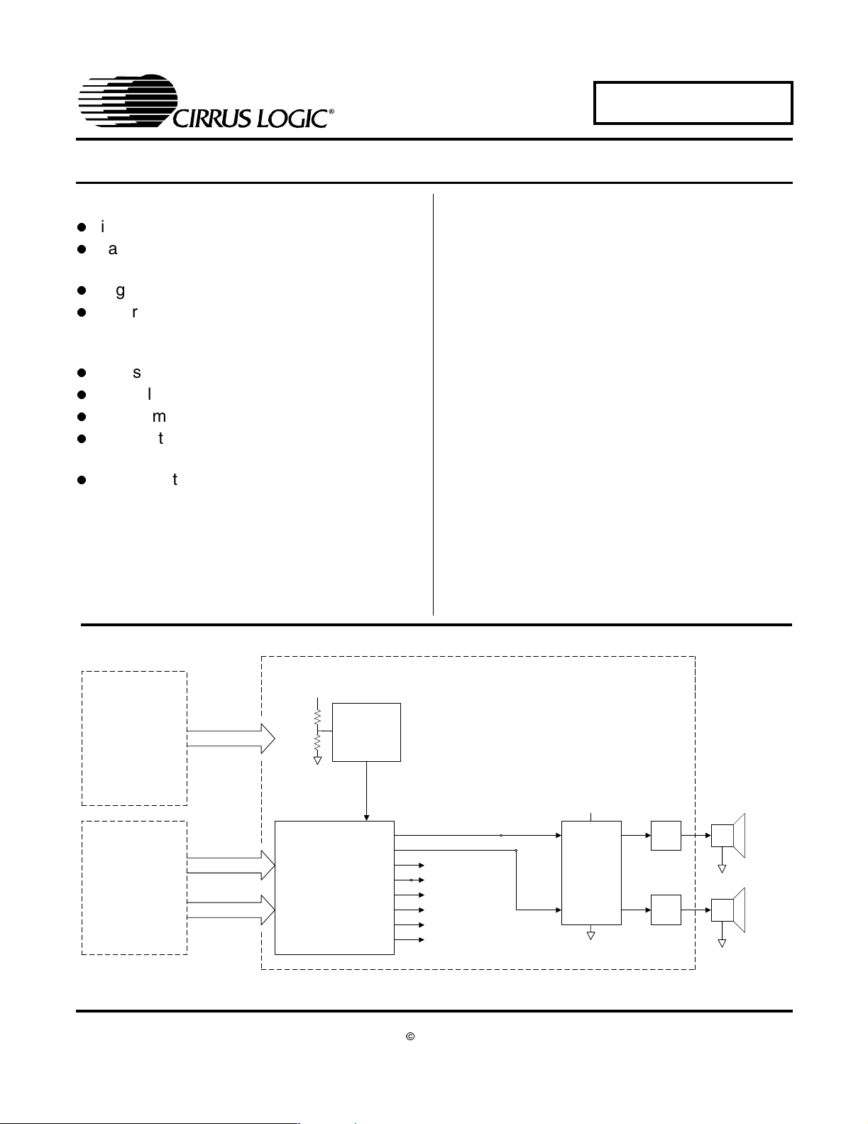
The CRD44800 PWM Amplifier demonstrates the
CS44800, Cirrus’ eight-channel pure digital PMW controller. This reference design implements an eightchannel amplifier which delivers 50 W per half-bridge
I
channel into 6 Ω loads using a single +45 V supply (at
10% THD+N). A 155 W Switched Mode Power Supply
(SMPS) is used to power the CRD44800.
As shown below, the CS44800 IC takes four stereo digital audio inputs in I²S format and converts them to PWM
outputs. This 64-pin LQFP IC provides an integrated
sample rate converter for 32 kHz-192 kHz input sample
rate support, volume up/down, speaker load compensation, PopGuard® to prevent pops in single voltage rail
half-bridge applications, peak limiting to prevent amplifier clipping, power supply ripple compensation, and AM
frequency interference elimination.
This reference design uses the the Philips TDA8939, an
integrated power stage back end for digital amplifiers
(four TDA8939 parts configured as half-bridges are used
for this eight-channel design). Current limiting and thermal protection are provided by the TDA8939.
The inductor/capacitor 2
nd
order low pass filter (LPF) removes high frequency components from the output
signal effectively converting it from digital to analog.
ORDERING INFORMATION
CRD44800 Reference Design
155W Switched Mode
Power Supply
Audio Driver Board
Cirrus Logic, Inc.
www.cirrus.com
+45V/+5V
I2S Clocks & Data
2
C Host Control
I
PSR Circuitry
+45V
CS4461 ADC
CS44800
(PWM Controller)
Copyright © Cirrus Logic, Inc. 2004
PWM Outputs
To channels 3/4
To channels 5/6
To channels 7/8
(All Rights Reserved)
+45V
LPF
Philips
TDA8939
LPF
Channels 1 and 2 (of 8)
6Ω
6Ω
DEC ‘04
DS632RD2
1

TABLE OF CONTENTS
1. SCHEMATIC DESCRIPTIONS ................................................................................................. 3
1.1 CRD44800 PWM Amplifier ................................................................................................ 3
1.2 CRD44800 Driver Board .................................................................................................... 3
1.3 Switched Mode Power Supply ........................................................................................... 4
2. OPERATION INFORMATION ................................................................................................... 5
2.1 Power Supply Ratings ...................................................................................................... 10
2.2 Power Supply Decoupling ................................................................................................ 10
2.3 Electromagnetic Interference (EMI) ................................................................................. 11
2.3.1 Suppression of EMI at the Source ...................................................................... 11
3. SCHEMATICS ......................................................................................................................... 13
4. LAYOUT .................................................................................................................................. 20
5. BILL OF MATERIALS ............................................................................................................ 23
6. TYPICAL PERFORMANCE PLOTS ....................................................................................... 25
7. REVISION HISTORY .............................................................................................................. 29
LIST OF FIGURES
Figure 1. Speaker Terminal Configuration ......................................................................................6
Figure 2. CS44800 Dialog Tab........................................................................................................ 8
Figure 3. Advanced Register Debug Tab - CS44800 ...................................................................... 9
Figure 4. Power and Connectors................................................................................................... 13
Figure 5. CS44800 ........................................................................................................................ 14
Figure 6. Left/Right Back Surround Channels............................................................................... 15
Figure 7. Left/Right Surround Channels ........................................................................................ 16
Figure 8. LFE/Center Channels..................................................................................................... 17
Figure 9. Left/Right Channels........................................................................................................18
Figure 10. PSR Feedback ............................................................................................................. 19
Figure 11. Silk Screen Top............................................................................................................ 20
Figure 12. Topside Layer .............................................................................................................. 21
Figure 13. Bottomside Layer ......................................................................................................... 22
Figure 14. Bill of Materials .............................................................................................................23
Figure 15. Bill of Materials .............................................................................................................24
Figure 16. Frequency Response...................................................................................................25
Figure 17. THD+N vs. Frequency at 1 W, 10 W, and 20 W .......................................................... 26
Figure 18. THD+N vs. Power at 1 kHz .......................................................................................... 27
Figure 19. FFT at -60 dBFS and 1 kHz ......................................................................................... 28
CRD44800
LIST OF TABLES
Table 1. RMS Output Voltage for Given Load Impedance .............................................................. 3
Table 2. Revision History .............................................................................................................. 29
2
CRD44800
1. SCHEMATIC DESCRIPTIONS
1.1 CRD44800 PWM Amplifier
The CS44800 shown in Figure 5 employs a built-in Sample Rate Converter (SRC) to support
all popular sampling frequencies between 32 kHz and 192 kHz. The CS44800 produces a
PWM frequency of either 384 kHz or 768 kHz (refer to CS44800 data sheet). In this design,
analog or digital audio signals are always output at a 384 kHz PWM rate.
The CS4461 ADC is used to monitor the signal and line frequency related ripple that is inevitable on the power supply rail when the amplifiers operate. The ripple voltage is digitized
and fed back to the CS44800. The CS44800 uses this information to substantially reduce
ripple related distortion and noise in the audio output signal.
Four Philips TDA8939 power stages provide the power back end to drive the speaker loads.
Each TDA8939 consists of a pair of over current and temperature protected half-bridge PWM
output stages. The TDA8939 is performance optimized for use in open loop Class D amplifier
systems. By changing the power supply voltage and/or the load impedance, RMS output
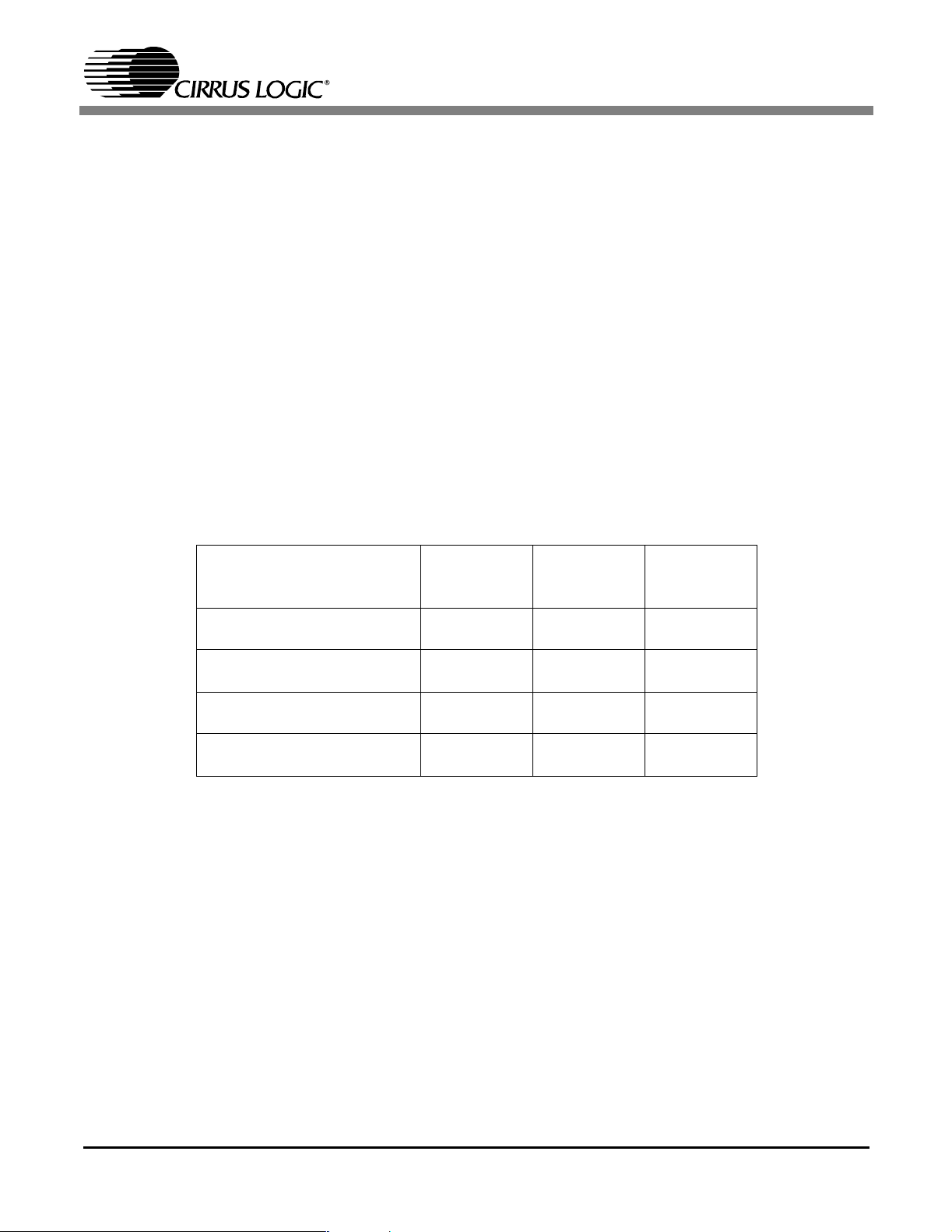
power at the speaker can be increased. Table 1 illustrates measured RMS output voltage
when using the TDA8939 configured as a half-bridge:
Supply Voltage
45 V 1% THD+N
10% THD+N
50 V 1% THD+N
10% THD+N
55 V 1% THD+N
10% THD+N
60 V 1% THD+N
10% THD+N
Table 1. RMS Output Voltage for Given Load Impedance
RMS Output
Power with an
8 Ω Load
25 W
38 W
32 W
47 W
38 W
57 W
44 W
67 W
RMS Output
Power with a
6 Ω Load
33 W
50 W
41 W
61 W
50 W
74 W
58 W
88 W
RMS Output
Power with a
4 Ω Load
47 W
70 W
57 W
86 W
69 W
105 W
81 W
124 W
1.2 CRD44800 Driver Board
The CRD44800 Driver board provides a convenient source of PCM I²S signals to drive the
CRD44800 PWM Amplifier board. Eight analog inputs allow multi-channel analog audio signals to be used for evaluation of the amplifier. In addition, either optical or coaxial stereo
S/PDIF signals can be used to evaluate the amplifier. In this case, the left and right channel
digital data are distributed to each of the additional channel pairs.
The CRD44800 Driver board provides two modes of operation: stand-alone and remote. In
the stand-alone mode, basic evaluation of the CS44800 is possible. The user can select between analog and digital S/PDIF input signals (jumpers J17 and J18), control the system volume, mute and unmute the system (switch S2), and ramp the PWM output up and down
(switch S3).
3

CRD44800
In the Remote mode, the DB-9 connector (J14, labelled RS-232) is connected to a host PC.
All aspects of the CS44800 may then be evaluated using the supplied software.
1.3 Switched Mode Power Supply
The SMPS used for the CRD44800 is a 155W OEM supply. The supply provides +45V for
the TDA8939 PWM back ends, and +5V to power all the signal level circuitry. The SMPS is
fully over-current and over-temperature protected.
4

CRD44800
2. OPERATION INFORMATION
Switches and Indicators (Located on the Driver Board):
RESET Pushbutton (S1) - forces a complete system reset.
MUTE Pushbutton (S2) - mutes the audio output of the CRD44800, but the PWM output stage
will continue switching.
RAMP UP/DN Pushbutton (S3) - forces a ramp down or a ramp up of the PWM switching output.
After a ramp down, the PWM output stage is no longer switching.
MUTE LED (D16) - indicates that the audio output is muted. The MUTE LED is also used during
CRD44800 initialization (see below).
FAULT LED (D19) - indicates several types of fault conditions. If one (or more) of the PWM outputs is shorted, or the PWM back end overheats, the FAULT LED will light. Also, if either the
Optical or Coax digital input is selected as the system input and a valid digital signal is not
present, the FAULT LED will light. The FAULT LED is also used during CRD44800 initialization
(see below).
S/PDIF ERROR LED (D6) - indicates the absence of a valid S/PDIF signal into the CS8416.
Stand-alone Operation
The CRD44800 evaluation system is prewired for operation. The SMPS is a universal input, 90260VAC, 50/60Hz.
1) Attach the supplied power cord to the power entry module. Do not turn on the power yet.
2) Configure jumper J10 for the desired volume control mode. If J10 is in, the gain of the
CS44800 will be forced to 0dB, irrespective of the position of the volume control pot. If J10 is
out, the volume control pot determines the CS44800 gain.
3) Configure jumpers J17 and J18 for the desired mode of operation. The first three options are
stand-alone, while the final option is remote.
Function J17 J18
Analog Inputs 1 - 2 1 - 2
Coaxial S/PDIF 2 - 3 1 - 2
Optical S/PDIF 1 - 2 2 - 3
Remote Mode 2 - 3 2 - 3
4) If the Analog input mode is selected, configure jumpers J6 and J7 to select the sampling frequency for the CS5341s.
Sample Rate (Fs) J6 J7
48 kHz 2 - 3 2 - 3
96 kHz 1 - 2 2 - 3
192 kHz 2 - 3 1 - 2
5
CRD44800
5) Supply either analog signals (if the Analog input option is selected) or either coaxial or optical
digital PCM inputs (if the digital S/PDIF option is selected).
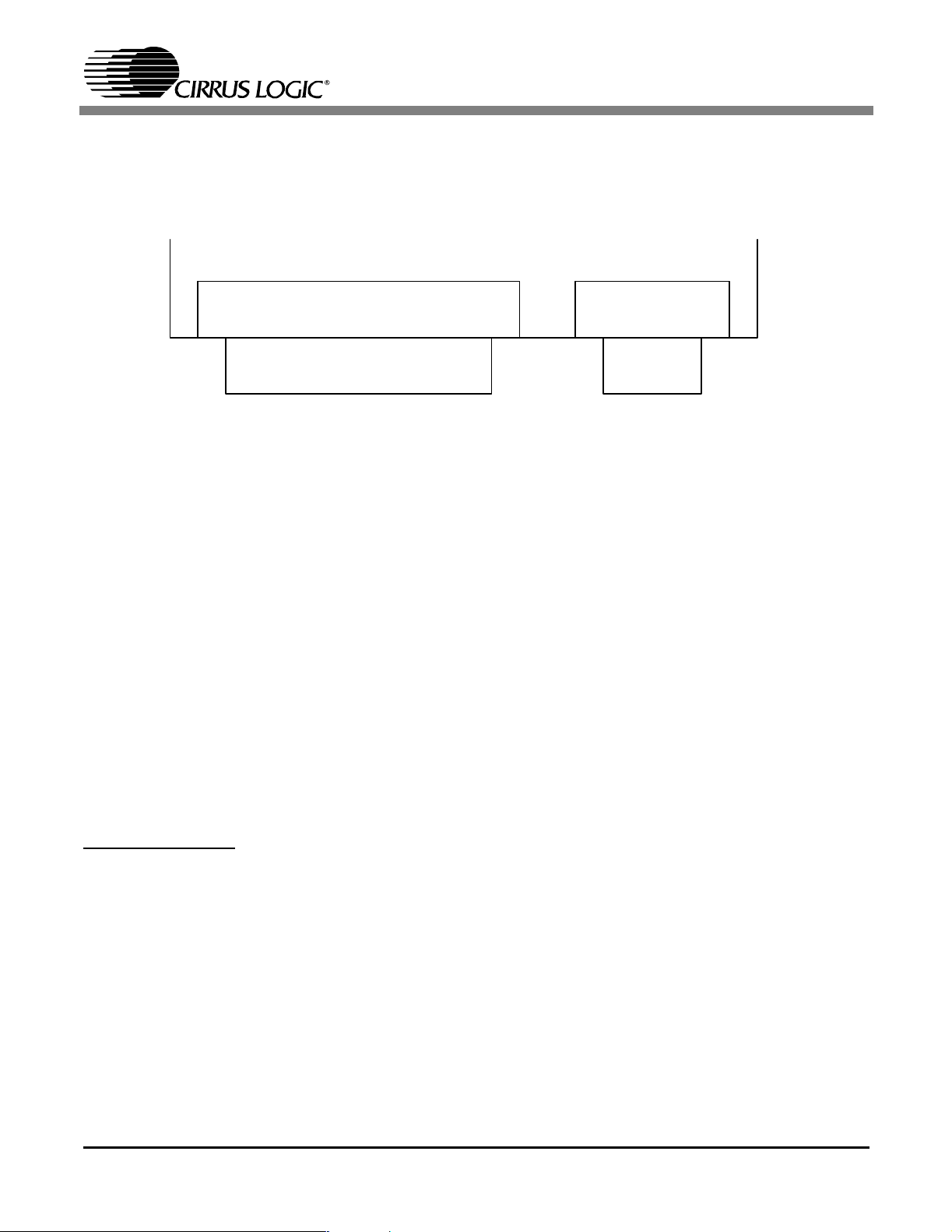
6) Connect loudspeakers to the speaker output terminals. The Red terminal is positive, and the
Black terminal is ground.
Rx Lx Rs Ls S C R L
Figure 1. Speaker Terminal Configuration
Turn the volume control fully counterclockwise and apply power using the power switch on the
power entry module. The Fault and Mute LEDs will both light briefly as the system is initialized.
Note that if either the Coax or the Optical input is selected, a valid digital signal must be provided
to the selected input so that the CRD44800 can complete initialization. If a valid signal is not
present at the selected input, both the Fault and Mute LEDs will remain lit.
If one of the stand-alone modes is selected, the amplifiers should now be operating. Slowly advance the volume control clockwise until the desired volume is achieved. The MUTE pushbutton
(S2) may be used to mute and unmute the audio output. The RAMP UP/DN pushbutton (S3) will
initiate a ramp up or ramp down of the audio output. Ramping down the audio output stops any
audio output. In order to avoid a “pop” in the speakers, you should ramp down the outputs before
turning off the AC power.
Note that in the stand-alone mode, several system faults are indicated by the lighting of the red
Fault LED, D19. Typical causes for fault conditions are short circuited speaker outputs, thermal
shutoff of the power back end, or lack of a S/PDIF signal when either of the S/PDIF inputs is selected.
Remote Operation
The CRD44800 may also be operated remotely via the Cirrus FlexGUI for complete control of all
the features of the CS44800. Note that the Fault and Mute LEDs operate differently in the remote
mode. They indicate the selected audio signal input as explained below. Follow the procedure
below to set up remote operation.
1) Attach the supplied power cord to the power entry module. Do not turn on the power yet.
2) Configure jumpers J17 and J18 for remote operation. Jumpers J17 and J18 should have pins
2 and 3 connected for remote operation. Jumpers J6 and J7 should be removed completely.
3) Turn on the AC power. Press the Reset button on the driver board. Select the desired audio
6

CRD44800
input source by pressing the Mute button. The following table shows the inputs selections:
Selected Input Mute LED Fault LED
Analog Inputs On Off
Optical S/PDIF Off On
Coaxial S/PDIF On On
4) Connect the DB-9 RS-232 port (J14) on the CRD44800 Driver board to a PC serial port.
5) Copy the CRD44800 directory from the included CD-ROM to the users local hard drive. Note
that FlexGUI is only compatible with systems running Windows 98 or better (i.e. Windows 98,
ME, 2000, XP, etc.).
6) Modify the following line in the file “flexconfig.ini”, which is found in the FlexLoader application
directory. This line is found in the [CDB44800Comm] section of the ini file.
SERIAL = PI_Serial.dll, 2500, COM1, 38400
Replace “COM1” with the number of the serial communications (RS-232) port you are using
(COM1/COM2/COM3/COM4).
7) Start FlexGUI opening FlexLoader.exe. This application can be used to read and modify any
CS44800 register, and provides easy control over individual channel volumes.
The CS44800 Dialog tab provides high level control over the CS44800’s registers. Controls are
provided to change volume, mute, power down, ramp control, quantization level, SAI input format, minimum pulse width, and channel delay.
7
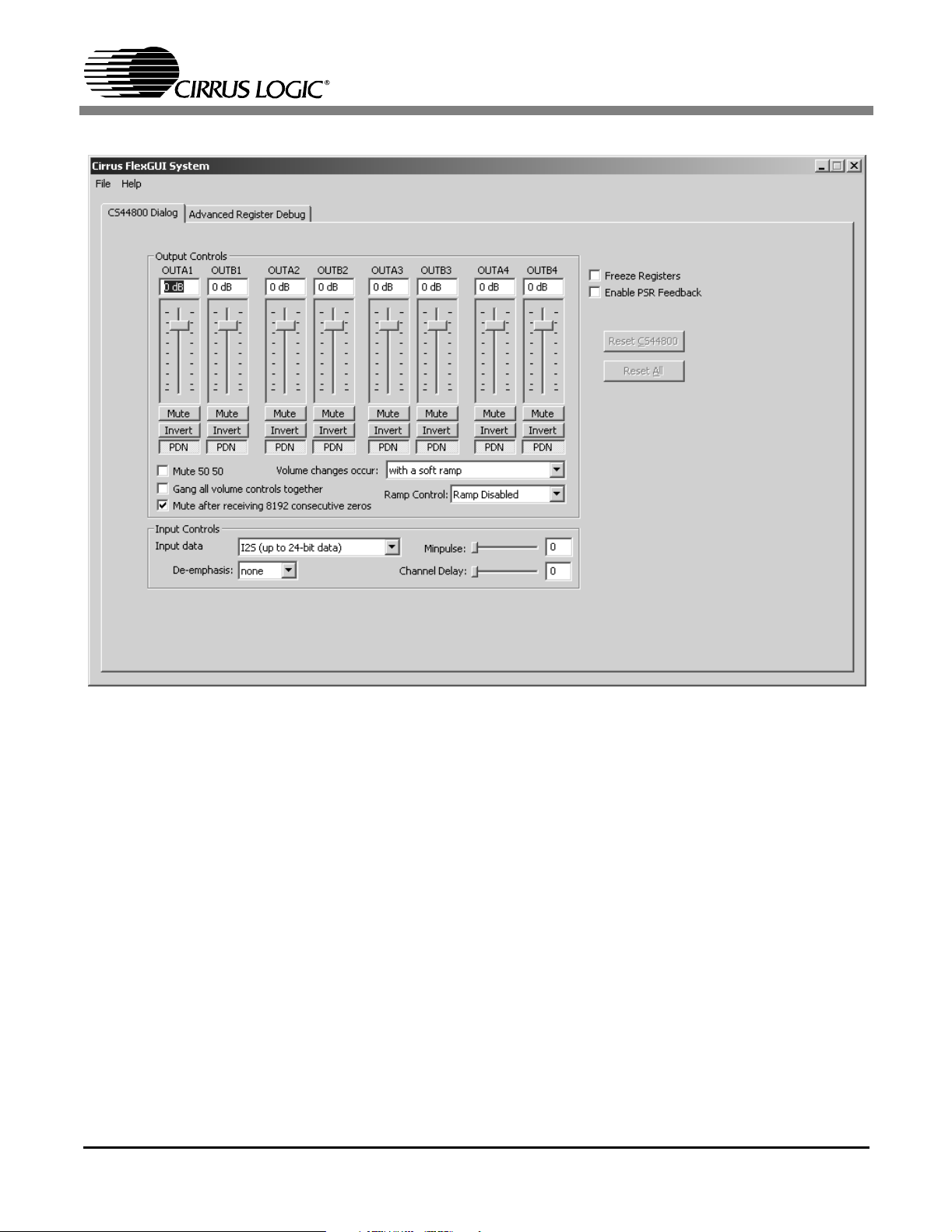
CRD44800
Figure 2. CS44800 Dialog Tab
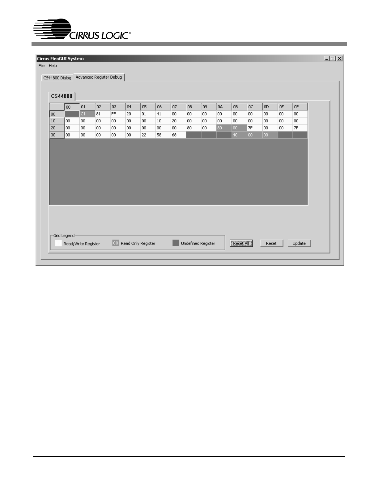
The Advanced Register Debug tab provides low level control over the CS44800 and CS8416 individual register settings. Each device is displayed on a separate tab. Register values can be
modified bitwise or bytewise. For bitwise, click the appropriate pushbutton for the desired bit. For
bytewise, the desired hex value can be typed directly in the register address box in the register
map.
8
CRD44800
Figure 3. Advanced Register Debug Tab - CS44800
9

CRD44800
System Issues
2.1 Power Supply Ratings
The required power supply current rating can be estimated as follows. 33 W is used as the
reference output power because this represents the typical full scale output with no clipping.
Assume the efficiency, η, is approximately 85% (this accounts for power to supply control
electronics and overhead), then for 33 W / 8 channels:
W
P
Total
P
Supply
Consequently the supply current is:
Supply
I
P
P
V
P
Supply
Out
η
Total
2
Supply
264
310
155
85.0
45
W
310
===
W
===
155
W
2
V
W
===
A
4.3
The factor of 2 in the denominator of the P
calculation arises from the fact that for typical
Supply
consumer applications in A/V or DVD receivers, the power supply should be capable of providing ½ the total requirement for all channels operating at full power. This design guide is
still quite conservative, and gives more that adequate headroom in real applications.
2.2 Power Supply Decoupling
Proper power supply decoupling is one key to maximizing the performance of a Class-D amplifier. Because the design uses an open loop output stage, noise on the power supply rail
will be coupled to the output. While the PSR functionality of the CS44800 helps reduce power
supply noise feedthrough to the output, careful decoupling of the power stage supply rails is
essential. Referring to Figure 11, the top side of the CRD44800 PWM amplifier board, good
decoupling practice is shown. Notice that the 0.1 µF ceramic capacitors are as close as
physically possible to the power pins of the TDA8939. The ground side of the capacitors is
connected directly to top side ground plane, which is also used by the power supply return
pins. This keeps the high frequency current loop small to minimize power supply variations
and EMI. 470 µF electrolytic capacitors are also located in close proximity to the power supply pins to supply the current locally for each channel. These are not required to be expensive
low ESR capacitors. General purpose electrolytic capacitors that are specified to handle the
ripple current can be used. The real time PSR feedback of the CS44800/CS4461 can greatly
attenuate the induced voltages due to the power supply ripple current.
10

CRD44800
2.3 Electromagnetic Interference (EMI)
The EMI challenges that face a maker of Class-D amplifiers are largely the same challenges
that have been faced by the switch mode power supply industry for many years. The numerous EMI consulting firms that have arisen and the many books that have been written on the
subject indicate the scope of potential problems and available solutions. They should be considered a resource - most makers of switch mode equipment would benefit from developing
a working relationship with a qualified EMI lab and from bringing their experience to bear on
design issues, preferably early in the design process.
This reference design from Cirrus Logic is a board level solution which is meant to control
emissions by minimizing and suppressing them at the source in contrast to containing them
in an enclosure.
The EMI requirements for an amplifier have added dimensions beyond those imposed on
power supplies. Audio amplifiers are usually located in close proximity to radio receivers, particularly AM receivers which are notoriously sensitive to interference. Amplifiers also need to
operate with speaker leads of unpredictable length and construction which make it possible
for any high frequency currents that appear on the outputs to generate nuisance emissions.
The criteria for judging successful EMI control is not as well defined for amplifier design as it
is for power supplies. While the techniques of measuring conducted and radiated emissions
are similar for both types of products, power supplies have a number of clearly defined (and
legally imposed) thresholds that are useful mainly as guidelines when testing amplifiers.
2.3.1 Suppression of EMI at the Source
Several techniques are used in the circuit design and board layout to minimize high frequency fields in the immediate vicinity of the high power components. Specific techniques
include the following:
• As was mentioned in Section 2.2, effective power supply decoupling of high frequency
currents, and minimizing the loop area of the decoupling loop is one aspect of minimizing EMI.
• Each output of the TDA8939 includes “snubbing” components. For example, OUT1 of
U4 includes snubber components R10 and R11 (5.6 Ω), and C36 and C39 (560 pF).
These components serve to damp ringing on the switching outputs in the 30-50 MHz
range. The snubbing components should be as close as practical to the output pins to
maximize their effectiveness. Again, refer to Figure 11 for the preferred component
layout.
• A separate ground plane with a solid electrical connection to the chassis and which
surrounds the speaker output connector should be implemented. This allows the
speaker outputs to be RF decoupled to the chassis just before they exit the chassis
from the speaker connector. Again, refer to Figure 11 for the preferred component layout.
• Make use of source termination resistors on all digital signals whose traces are longer
11

CRD44800
than about 25 mm.
It is extremely critical that the layout of the power amplifier section of the Cirrus Logic
CS44800 Reference Design be copied as exactly as possible to assure best RF/EMI performance.
12

3. SCHEMATICS
CRD44800
Figure 4. Power and Connectors
13

CRD44800
Figure 5. CS44800
14

CRD44800
Figure 6. Left/Right Back Surround Channels
15

CRD44800
16
Figure 7. Left/Right Surround Channels

CRD44800
Figure 8. LFE/Center Channels
17

CRD44800
18
Figure 9. Left/Right Channels

CRD44800
Figure 10. PSR Feedback
19

4. LAYOUT
CRD44800
20
Figure 11. Silk Screen Top

CRD44800
Figure 12. Topside Layer
21

CRD44800
22
Figure 13. Bottomside Layer

5. BILL OF MATERIALS
CRD44800
PANASONIC ECJ2VB1H102K
C124 C127 C132 C133
C135 C136 C137 C138
C139 C140 C141 C142
NICHICON UPW1H102MHD
C143
C113 C120
BC COMPONENTS 2222 370 11474
PANASONIC ECA1HM471
C114 C119
PANASONIC ECJ2VC1H561J
C105 C106
C77 C78 C89 C90 C99
PANASONIC ECJ1VF1E104Z
KEMET C0805C104K5RAC
C100 C111 C112 C121
C122
C24 C25 C26 C27 C126
C49 C50 C53 C54 C55 C56
C57 C58 C59 C60 C63 C64
C65 C66 C79 C80 C81 C82
311-00001-01
KEMET C1206C224K5RAC
LTD
C85 C86 C87 C88 C101
C102 C103 C107 C108
C109 C110 C123 C125
C115 C118
PT-422-03
PT-1222P-03
INDUSTRIES
INDUSTRIES
Figure 14. Bill of Materials
Rev Description Qty U/M Reference Designator MFG MFG. P/N
Line
Item
1 A CAP 1000pF ±10% 50V X7R 0603 2 EA C145 C146 PANASONIC ECJ1VB1H102M
2 A CAP 1000pF ±10% 50V X7R 0805 19 EA C9 C10 C19 C21 C34 C104
3 A CAP 1uF ±10% 25V X7R 1206 1 EA C28 PANASONIC ECJ3YB1E105K
4 A CAP 1000uF ±20% 50V ELEC RAD 16x25m 8 EA C37 C44 C69 C76 C91 C98
5 A CAP 120pF ±5% 50V C0G 0603 2 EA C12 C13 KEMET C0603C121J5GAC
6 A CAP 2200pF ±10% 50V X7R 0603 1 EA C14 KEMET C0603C222K5RAC
7 A CAP 22uF ±20% 6.3V ELEC RAD 5 EA C3 C4 C6 C7 C33 PANASONIC ECEA0JKS220
8 A CAP 39pF ±5% 50V C0G 0603 2 EA C11 C30 KEMET C0603C390J5GAC
9 A CAP 0.47uF ±10% 63V MTL FLM RAD 8 EA C16 C43 C70 C75 C92 C97
10 A CAP 470uF ±20% 50V ELEC RAD 8 EA C51 C52 C61 C62 C83 C84
11 A CAP 47uF ±20% 16V ELEC RAD 6.3x11MM 2 EA C15 C31 PANASONIC ECEA1CKS470
12 A CAP 560pF ±5% 50V C0G 0805 16 EA C35 C36 C45 C46 C67 C68
13 A CAP 0.1uF +80/-20% 25V Y5V 0603 11 EA C1 C2 C18 C20 C22 C23
14 A CAP 0.1uF ±10% 50V X7R 0805 37 EA C17 C29 C32 C38 C47 C48
15 A CAP 0.22uF ±10% 50V X7R 1206 8 EA C39 C42 C71 C74 C93 C96
16 A HEATSINK, 30W, APOGEE PWM 1 EA HS1 SUMMIT HEAT SINKS CO
17 A CONN, FLEX 22PIN, ST, I mm PITCH 1 EA J2 HIROSE FH21-22S-1DSA
18 A CONN, 8PIN EH 2.5MM PTCH PWR HDR 1 EA J1 JST B8B-EH-A
19 A CONN, 2x2 SPKR TERMINAL 1 EA J5 DRAGON CITY
20 A CONN, 6x2 SPKR TERMINAL 1 EA J4 DRAGON CITY
23

CRD44800
DALE CRCW06031000F
R89 R101 R110 R111 R112
R113 R114 R115 R116
R117 R118
DALE CRCW080522R1F
DALE CRCW12062201F
PANASONIC ERJ3GEYJ473V
PANASONIC ERJ6ENF47R5V
R92 R95
R93 R94
R109
R33 R34
YAGEO 9C12063A5101JLHFT
DALE CRCW20105R6J
R62 R64
R29 R36 R70 R77 R82 R83
R90 R91 R96 R97
Figure 15. Bill of Materials
24
Rev Description Qty U/M Reference Designator MFG MFG. P/N
Line
Item
21 A IND, 22UH, 3.5A 8 EA L5 L6 L7 L8 L9 L10 L11 L12 TRANSTEK MAGNETICS TMP50612CT
22 A RES 10 OHM 1/10W ±5% 0603 1 EA R71 PANASONIC ERJ3GEYJ100V
23 A RES 10.2 OHM 1/16W ±1% 0603 FILM 1 EA R56 DALE CRCW060310R2F
24 A RES 100 OHM 1/16W ±1% 0603 FILM 17 EA R59 R75 R85 R86 R87 R88
25 A RES 10k OHM 1/16W ±1% 0603 FILM 2 EA R5 R65 PANASONIC ERJ3EKF1002V
26 A RES 121 OHM 1/16W ±1% 0603 FILM 3 EA R1 R3 R4 DALE CRCW06031210F
27 A RES 1.96k OHM 1/16W ±1% 0603 FILM 1 EA R48 DALE CRCW06031961F
28 A RES 200 OHM 1/16W ±1% 0603 FILM 1 EA R2 DALE CRCW06032000F
29 A RES 2k OHM 1/16W ±1% 0603 FILM 2 EA R54 R55 DALE CRCW06032001F
30 A RES 22.1 OHM 1/10W ±1% 0805 FILM 8 EA R11 R14 R24 R27 R78 R81
31 A RES 2.2k OHM 1/8W ±1% 1206 FILM 8 EA R12 R13 R25 R26 R79 R80
32 A RES 46.4k OHM 1/16W ±1% 0603 FILM 1 EA R49 DALE CRCW06034642F
33 A RES 47k OHM 1/10W ±5% 0603 FILM 6 EA R16 R30 R42 R76 R84
34 A RES 47.5 OHM 1/10W ±1% 0805 FILM 8 EA R18 R19 R20 R21 R31 R32
35 A RES 49.9 OHM 1/16W ±1% 0603 FILM 4 EA R6 R7 R44 R58 DALE CRCW060349R9F
36 A RES 49.9k OHM 1/16W ±1% 0603 FILM 1 EA R57 DALE CRCW06034992F
37 A RES 5.1K OHM 1/4W +5% 1206 8 EA R37 R38 R41 R45 R47 R51
NO POP 4 EA R17 R35 R39 R40
38 A RES 5.6 OHM 1/2W ±5% 2010 FILM 16 EA R9 R10 R15 R22 R23 R28
39 A RES 649 OHM 1/16W ±1% 0603 FILM 1 EA R8 DALE CRCW06036490F
40 A RES 90.9 OHM 1/16W ±1% 0603 FILM 2 EA R52 R53 PANASONIC ERJ3EKF90R9V
41 D IC CRUS A/D PSR FEEDBACK TSSOP24 1 EA U12 CIRRUS LOGIC CS4461-CZZ/D
42 A IC CRUS, MULTI CHNL PWM CONTR QFP64 1 EA U11 CIRRUS LOGIC CS44800-CQ/A
43 A IC, 1.5A ADJ V REG, TO-252 2 EA U1 U2 NJR NJM317DL1
44 A IC LNR DUAL OP AMP LOW V RRO VSP8 1 EA U3 NJR NJM2140R
45 A IC LOG CLASS D PWR COMP HSOP24 4 EA U4 U5 U6 U7 PHILLIPS TDA8939TH
46 A OSC, 24.576MHz 100ppm 5V, SG-531 1 EA U14 CITIZEN CMX309FLC24.576MT
47 A SCREW PANHEAD, 4-40, PH, 1/2"L 5 EA BUILDING FASTENERS PMS 440 0050 PH

6. TYPICAL PERFORMANCE PLOTS
CRD44800
+1
+0.5
-0
-0.5
-1
-1.5
-2
-2.5
-3
-3.5
-4
Hz
Figure 16. Frequency Response
20 20k50 100 200 500 1k 2k 5k 10k
-5
-4.5
d
B
r
A
25

20 W
CRD44800
1 W
1
0.5
0.2
0.1
10 W
0.05
0.02
0.01
0.005
0.002
Hz
Figure 17. THD+N vs. Frequency at 1 W, 10 W, and 20 W
20 20k50 100 200 500 1k 2k 5k 10k
0.001
26
%

CRD44800
10
5
2
1
0.5
0.2
0.1
0.05
0.02
W
Figure 18. THD+N vs. Power at 1 kHz
100m 50200m 500m 1 2 5 10 20
0.01
%
27

CRD44800
+0
-10
-20
-30
-40
-50
-60
-70
-80
-90
-100
-110
-120
-130
Hz
Figure 19. FFT at -60 dBFS and 1 kHz
20 20k50 100 200 500 1k 2k 5k 10k
-140
28
d
B
r
A

7. REVISION HISTORY
Release Date Changes
RD1 June 2004 1st Release
RD2 December 2004 2nd Release
-Updated schematics and layout to reflect rev B.
CRD44800
Table 2. Revision History
Contacting Cirrus Logic Support
For all product questions and inquiries contact a Cirrus Logic Sales Representative.
To find one nearest you go to http://www.cirrus.com/
IMPORTANT NOTICE
Cirrus Logic, Inc. and its subsidiaries ("Cirrus") believe that the information contained in this document is accurate and reliabl e. However, the information is subject
to change wi thout notice and is provided "AS IS" wit hout warranty of any kind (express or implied). Customers are advised to obtain the latest version of relevant
information to verify, before placing orders, that info rmation bei ng relied on is current and complete. All products are sold subject to the terms and condi tions of sale
supplied at the time of order acknowledgment, including those pertaining to warranty, indemnification, and limitat ion of liability. No responsibility is assumed by Cirrus
for the use of this information, including use of this information as the basis for manufacture or sale of any items, or for infringement of patents or o ther rights of third
parties. This document is the property of Cirr us and by furnishing this information, Cirrus grants no license, express or implied under any patents, mask work rights,
copyrights, trademarks, trade secrets or other intellectual property rights. Cirrus owns the copyrights associated with the information contai ned herein and gives consent for copies to be made of the information onl y for use within your organization with respect to Cirrus integrated circuit s or other products of Cirrus. This consent
does not extend to other copying such as copyi ng for general distribution, advertising or promotional purposes, or for creating any work for resale.
CERTAIN APPLICATIONS USING SEMICONDUCTOR PRODUCTS MAY INVOLVE POTENTIAL RISKS OF DEATH, PERSONAL INJURY, OR SEVERE PROPERTY OR ENVIRONMENTAL DAMAGE (“CRITICAL APPLICATIONS”). CIRRUS PRODUCTS ARE NOT DESIGNED, AUTHORIZED OR WARRANTED FOR USE
IN AIRCRAFT SYSTEMS, MILITARY APPLICATI ONS, PRODUCTS SURGI CALLY IMPLANTED INTO THE BODY, AUTOMOTIVE SAFETY, SECURITY DEVICES,
LIFE SUPPORT PRODUCTS OR OTHER CRITICAL. INCLUSION OF CIRRUS PRODUCTS IN SUCH APPLICATIONS IS UNDERSTOOD TO BE FULLY AT THE
CUSTOMER’S RISK AND CIRRUS DISCLAIMS AND MAKES NO WARRANTY, EXPRESS, STATUTORY OR IMPLIED, INCLUDING THE IMPLIED WARRANTIES
OF MERCHANTABILITY AND FITNESS FOR PARTICULAR PURPOSE, WITH REGARD TO ANY CIRRUS PRODUCT THAT I S USED IN SUCH A MANNER. IF
THE CUSTOMER OR CUSTOMER’S CUSTOMER USES OR PERMITS THE USE OF CIRRUS PRODUCTS IN CRI TICAL APPLICATI ONS, CUSTOMER AGREES,
BY SUCH USE, TO FULLY INDEMNIFY CIRRUS, ITS OFFICERS, DI RECTORS, EMPLOYEES, DISTRIBUTORS AND OTHER AGENTS FROM ANY AND ALL
LIABILITY, INCLUDING ATTORNEYS’ FEES AND COSTS, THAT MAY RESULT FROM OR ARI SE IN CONNECTION WITH THESE USES.
Cirrus Logic, Cirrus, the Cirrus Logic logo designs, and Popguard are trademarks of Ci rrus Logic, Inc. All other brand and product names in this document may be
trademarks or service marks of their respective owners.
29
 Loading...