

Page 1
Reference Design for CS42L51
CRD42L51
Features
! Ultra Small Layout
! Single AAA Battery Source
! 1/8” Stereo Input Allows up to 2 Vrms Signals
! On-Board MIC
! 1/8” Stereo Headphone Output Jack
! S/PDIF Input (CS8416 Receiver)
! Flexible User Interface
– 2 Pushbuttons Enable, Disable and
Navigate between Reset, Standby, Input
Source and Effects Options
– 2 Pushbuttons Adjust Volume and Effects
CRD42L51 Actual Size
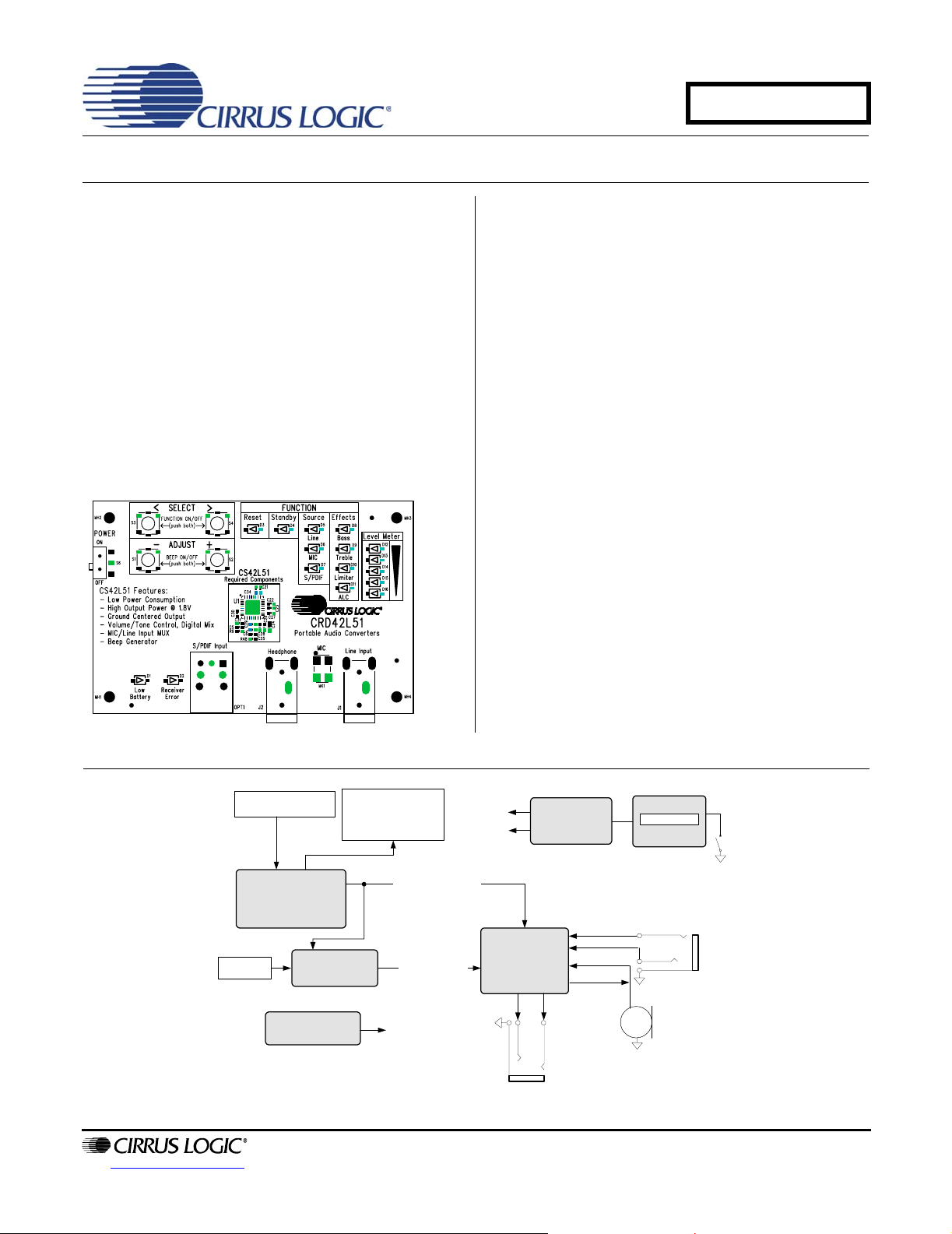
Description
The CRD42L51 evaluation board provides a quick and
easy evaluation of select features in the CS42L51 Low
Power, Stereo CODEC. Four pushbuttons and sixteen
LED’s comprise the user interface, allowing manipulation of the CS42L51’s registers and control clock/data
routing between the CODEC, crystal oscillator, and
S/PDIF Receiver.
Two 1/8” stereo jacks provide analog input and output
connections, and a S/PDIF optical receiver provides a
digital input connection. An on-board microphone demonstrates the high dynamic range of the CS42L51’s
Programmable Gain Amplifier (PGA) and MIC preamplifier.
Power is derived from a single AAA battery boosted up
to 3.3 V for the interface and control logic, then regulated down to 1.8 V for the CS42L51 ’s anal og/digital co re
and headphone supply.
The CRD42L51 highlights the ultra small layout required for the CS42L51. Required components include
only a few small ceramic capacitors and resistors.
ORDERING INFORMATION
CRD42L51 Reference Design
Push Buttons
Microcontroller
Optical
Input Jack
CS8416
12.2880 MHz
Oscillator
LED Selection
Indicators
I²C Control/Reset
Clocks/Data
Master Clock
+3.3 V
+1.8 V
CS42L51
Step Up DC-DC
Converter w/
Linear Reg.
1/8" Stereo
Headphone Jack
AAA
Battery Clip
1/8" Stereo Line
Input Jack
Omni-directional
Microphone
http://www.cirrus.com
Copyright © Cirrus Logic, Inc. 2005
(All Rights Reserved)
DECEMBER '05
DS679RD1
Page 2

TABLE OF CONTENTS
1. QUICK-START GUIDE ........................................................................................................................... 3
2. FUNCTION & LEVEL DETAILS ............................................................................................................ 4
3. SYSTEM OVERVIEW ............................................................................................................................. 5
3.1 Power (U2) ..................................................................................................................................... 5
3.2 Microcontroller (U5) ........................................................................................................................ 5
3.3 CS42L51 Audio CODEC (U1) ........................................................................................................ 5
3.4 CS8416 Digital Audio Receiver (U4) .............................................................................................. 5
3.5 Oscillator (Y1) ................................................................................................................................. 5
3.6 Analog Input ................................................................................................................................... 5
3.7 Analog Outputs ............................................................................................................................... 5
3.8 Switch & Pushbutton ...................................................................................................................... 6
3.9 LEDs ............................................................................................................................................... 6
3.10 Error Indicators ........................................... ... ... .... ... ... ... .... ........................................................... 6
3.11 Layout .................. ... .... ... ... ....................................... ... ... .... ... ........................................................ 6
4. SYSTEM CONNECTIONS & INTERFACE ............................................................................................. 7
5. CRD42L51 SCHEMATICS ..................................................................................................................... 9
6. CRD42L51 LAYOUT ........................................................................................................................... 13
7. REVISION HISTORY ............................................................................................................................ 19
LIST OF FIGURES
Figure 1. Block Diagram............................................................................................................................... 8
Figure 2. CS42L51 and Analog I/O (Schematic Sheet 1) .................................................................... ... .... .9
Figure 3. S/PDIF Input (Schematic Sheet 2).............................................................................................. 10
Figure 4. Microcontroller, Pushbuttons and LED Indicators (Schematic Sheet 3) ..................................... 11
Figure 5. DC-DC Converter and AAA Battery Clip (Schematic Sheet 4)................................................... 12
Figure 6. Silk Screen Top........................... ... ... ... .... ... ... ... ....................................... ... .... ... ... ...................... 13
Figure 7. Silk Screen Bottom ..................................................... ... .... ... ... ... ... .... ......................................... 14
Figure 8. Top-Side Layer ........................................................................................................................... 15
Figure 9. Internal Layer (Ground Plane) ................................................. ... ... ............................................. 16
Figure 10. Internal Layer (Power Plane).................................................................................................... 17
Figure 11. Bottom-Side Layer.................................................................................................................... 18
CRD42L51
2 DS679RD1
Page 3
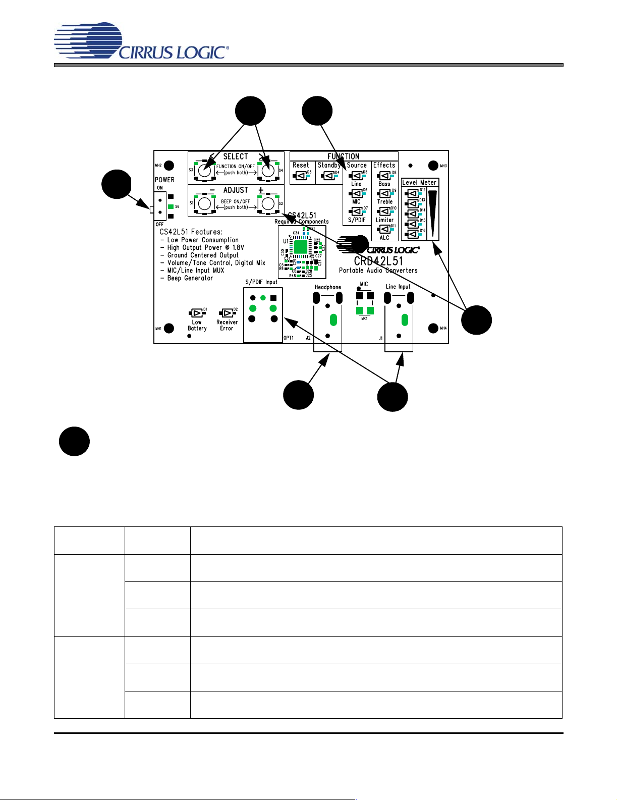
1. QUICK-START GUIDE
y
t
/
CRD42L51
4. Push both SELECT buttons simultaneously to turn off the Reset function.
The board will enter Standby for a moment and
then automatically activate the Line function.
3
3. Switch the power
switch to the ON position.
battery, installed on the
back side, is required.)
The Reset Function will
activate. No selections or
adjustments can be
made while Reset is on.
(NOTE: 1 AAA
1. Begin by connecting 16 Ω
or 32 Ω headphones.
7. Speak into the microphone or activate the external S/PDIF or Line player to begin evaluation.
7
4
1
5. Use any one of the SELECT buttons to navigate
between and shift the focus to select functions.
5
To turn selected functions on or off, push both SELECT buttons simultaneously. The assocated LED will turn on or off.
6. Use any one of the ADJUST buttons to control
the volume/ threshold
level of each Source/Effects that receives focus.
The Level Meter will briefl
display a pre-defined gradien
that represents the volume
threshold level in dBs. The optimal/default level flashes for a
few seconds.
6
2. Connect the desired interface. Apply up to 2 Vrms to the Line
2
Input. For smaller signals, enable the
ALC function for automatic level control (up to +12 dB analog gain). For digital source, connect optical cable to
S/PDIF Input
Pushbutton
Control Key Press Description
<
(only)
SELECT
ADJUST
DS679RD1 3
>
(only)
< AND >
(simultaneously)
-
(only)
+
(only)
- AND +
(simultaneously)
Left/Up Navigation - Shifts the focus between functions. A blinking LED indicates which func-
tion has received focus.
Right/Down Navigation - Shifts the focus between functions. A blinking LED indicates which
function has received focus.
Enables/Disables the function that is in-focus. When the selected function is enabled AND
in-focus, the associated LED blinks ON, periodically, with a longer duty cycle.
Decreases the volume level of the function that is in-focus.
Increases the threshold level of the ALC/Limiter when either is in-focus.
Increases the volume level of the function that is in-focus.
Decreases the threshold level of the ALC/Limiter when either is in-focus.
Enables/Disables confirmation/error beeps.
Page 4
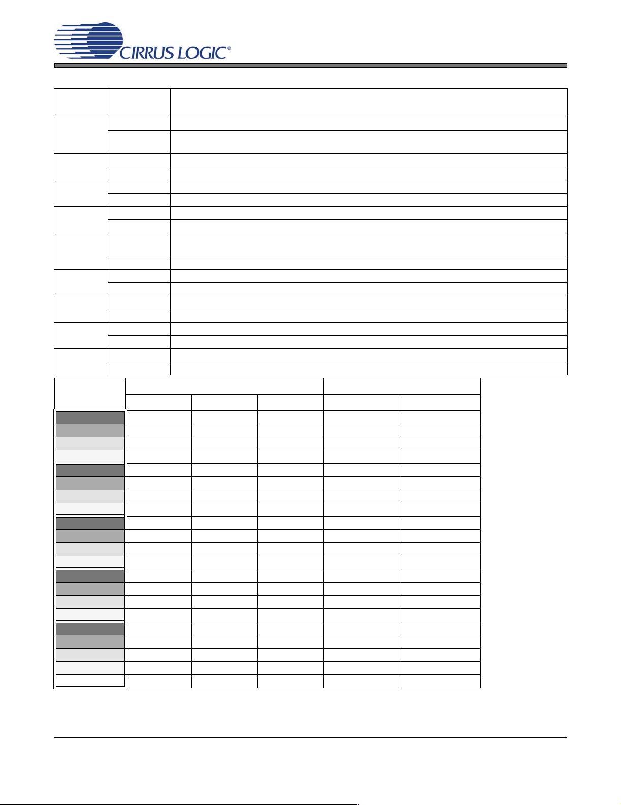
2. FUNCTION & LEVEL DETAILS
State/LED
Function
Reset
Standby
Line
MIC
S/PDIF
Bass
Treble
Limiter
ALC
Illumination Description
ON CS42L51, CS8416, optical receiver, oscillator held in reset and disabled.
OFF
ON CS8416, optical receiver, oscillator held in reset and disabled; CS42L51 soft powered down.
OFF All devices out of reset; CS42L51 powered up, register settings restored.
ON Stereo Line Input selected, unmuted; MIC powered down.
OFF Stereo Line Input muted.
ON Mono MIC selected, powered up, unmuted; Line disabled.
OFF MIC muted.
ON
OFF S/PDIF Input muted; CS8416 and optical receiver powered down.
ON Tone Control enabled, Bass corner frequency set to 200 Hz, Treble corner frequency set to 7 kHz.
OFF Tone Control (Bass and Treble) disabled.
ON Tone Control enabled, Bass corner frequency set to 200 Hz, Treble corner frequency set to 7 kHz.
OFF Tone Control (Bass and Treble) disabled.
ON Limiter enabled, attack rate set to 0x02, release rate set to 0x3D.
OFF Limiter disabled.
ON ALC enabled, attack rate set to 0x02, release rate set to 0x3D.
OFF ALC disabled.
CS42L51, oscillator out of reset. CS8416 and optical receiver controlled by S/PDIF function. The Line function
is enabled automatically.
S/PDIF Input selected, unmuted; CS8416 and optical receiver powered up. (Line or MIC mixed with S/PDIF if
enabled.)
CRD42L51
Level Meter
(LED Luminosity)
LED12_ON +6.0 +44.0 +12.0 -18.0 -24.0
LED12_75% +4.0 +42.5 +10.5 - -
LED12_50% +2.0 +41.0 - - -
LED12_25% +0.0 +39.5 +9.0 - -
LED13_ON -1.5 +38.0 +7.5 -12.0 -18.0
LED13_75% -3.0 +36.5 +6.0 - -
LED13_50% -4.5 +35.0 - - -
LED13_25% -6.0 (default) +33.5 +4.5 - -
LED14_ON -7.5 +32.0 (default) +3.0 -9.0 -12.0
LED14_75% -9.0 +30.5 +1.5 - -
LED14_50% -11.0 +29.0 - - -
LED14_25% -13.0 +27.5 +0.0 (default) - -
LED15_ON -16.0 +26.0 -1.5 -6.0 (default) -9.0 (default)
LED15_75% -19.0 +24.5 -3.0 - -
LED15_50% -22.0 +23.0 - - -
LED15_25% -26.0 +21.5 -4.5 - -
LED16_ON -30.0 +20.0 -6.0 -3.0 -6.0
LED16_75% -35.0 +18.5 -7.5 - -
LED16_50% -40.0 +17.0 - - -
LED16_25% -45.0 +15.5 -9.0 - -
LED16_OFF -51.5 +14.0 -10.5 +0.0 -3.0
Line/SPDIF MIC Bass/Treble MAX MIN/Cushion
Level (dB) ALC/Limiter Threshold (dB)
4 DS679RD1
Page 5

CRD42L51
3. SYSTEM OVERVIEW
The CRD42L51 reference design provides a quick and general overview of the features in the CS42L51 CODEC
and provides a reference of an ultra small lay ou t de sign. Line, MIC and S/PDIF sources are accomodated, and a
microcontroller automatically configures the board and the CODEC’s internal registers for straightforward operation.
The CRD42L51 schematic-set has been partitioned into four pages and is shown in Figures 2 through 5.
3.1 Power (U2)
Power is supplied to the board through a single AAA battery. A DC-DC Converter boosts the battery’s voltage to 3.3 V which is then regulated down to 1.8 V. The CS42L51 is powered fro m 1.8 V, demonstrating its
internal ground-centered amplifier’s ability to deliver ample power into headphone loads even at low supply
voltages. The interface logic between the CS8416, oscillator and CS42L51 operates at 3.3 V.
3.2 Microcontroller (U5)
The microcontroller controls digital signal routing between the CS42L51, CS8416 and oscillator in response
to user input via four pushbuttons. It automatically initializes the board to predefined settings once power is
applied.
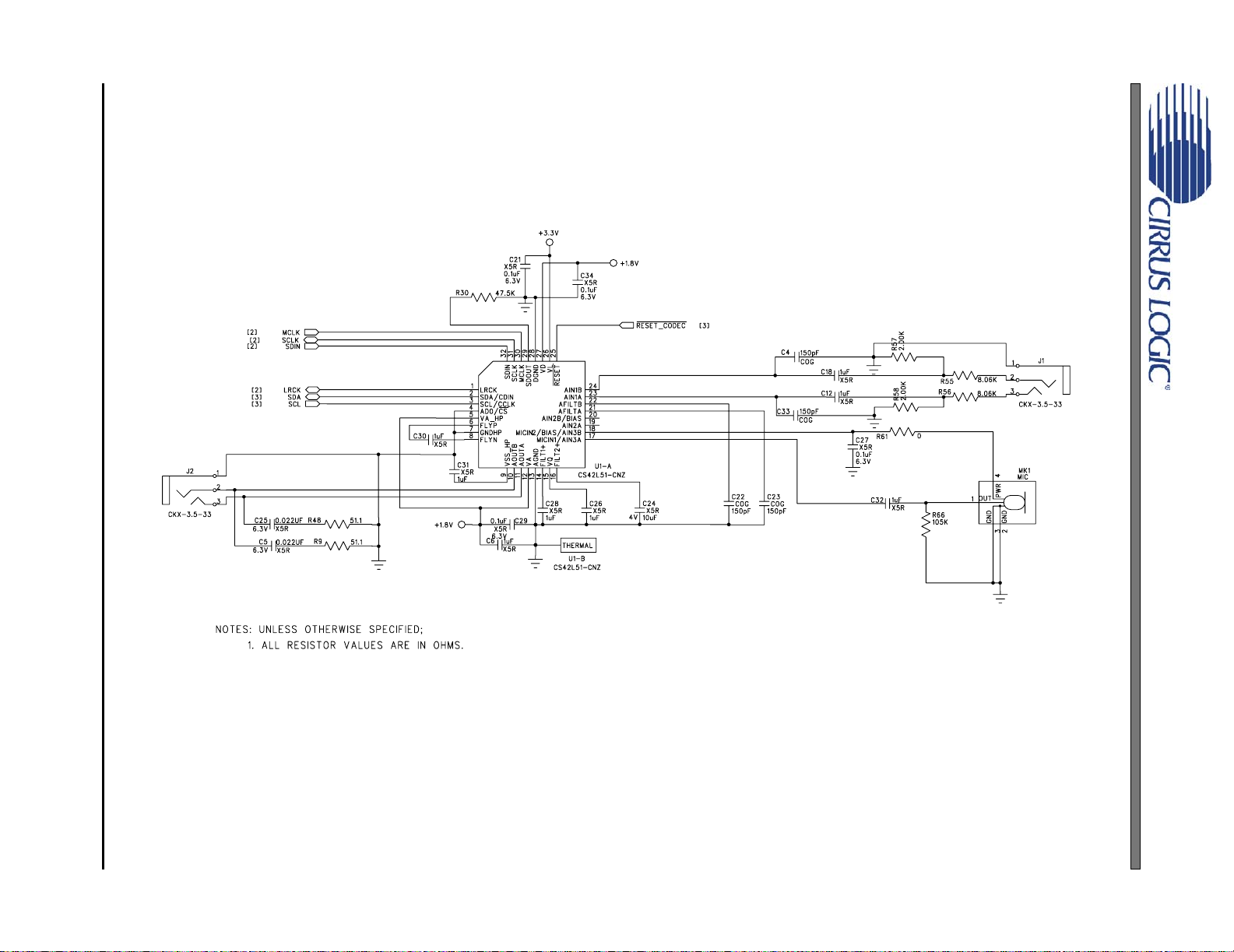
3.3 CS42L51 Audio CODEC (U1)
A complete description of the CS42L51 (Figure 2 on page 9) is included in the CS42L51 product d ata sheet.
The CS42L51 is automatically configured by the microcontroller to the default settings following a power-on
condition and later modified based on user input via four pushbuttons. See Section 2 for a description of
each functional mode and the associated configuration setting for the CS42L51.
3.4 CS8416 Digital Audio Receiver (U4)
A complete description of the CS8416 receiver (Figure 3 on page 10) and a discussion of the digital audio
interface are included in the CS8416 data sheet.
The CS8416 converts the input S/PDIF data stream from the optical connector into PCM data for the
CS42L51. The S/PDIF input may be mixed with the Line or MIC input. In this case, the CODEC clock source
comes from the CS8416. Should the S/PDIF source become unavailable, causing a Receiver Error, the microcontroller will automatically switch the system master clock to the oscillator for uninterrupted operation
of the Line or MIC input.
3.5 Oscillator (Y1)
The on-board oscillator provides the system master clock when the digital audio receiver is powered down
or when a Receiver Error occurs. Selections are automatically de termined ba sed on user input an d system
status.
3.6 Analog Input
An 1/8” jack supplies the line-level analog inputs through an AC-coupled passive filter. Voltage dividers before the inputs to the CS42L51 allow up to 2 Vrms signals (NOTE: To amplify smaller signals, enable the
Automatic Level Control (ALC). The CS42L51 applies up to +12 dB analog gain, as ne eded, using the ALC
together with the integrated Programmable Gain Amplifier (PGA)). A surface-mount microphone connects
to one of the inputs of the CS42L51 and is mux’d with the Line input. Either the Line or MIC input may be
mixed with the S/PDIF input.
3.7 Analog Outputs
An 1/8” jack outputs the signal from the CS42L51’s ground-centered headphone amplifier. The load stabilizer circuitry made up of a resistor/capacitor pair allow the amplifier to drive headphone in addition to linelevel loads.
DS679RD1 5
Page 6

3.8 Switch & Pushbutton
The POWER switch engages the AAA battery when switched to the ON position. Power is applied to the
board and the microcontroller initializes. T he SELECT push button switches allow the user to navig ate back
and forth between the FUNCTION options. When both SELECT buttons are pushed simultaneously, the
state of the function that receives focus (indicated by a blinking LED) is toggled. The ADJUST buttons allow
the user to apply gain, attenuation and move the threshold levels of the ALC and Limiter (the level of each
is shown in the Level Meter LED’s). When both ADJUST buttons are pushed simultaneously, the state of
the CS42L51’s internal beep generator is toggled.
3.9 LEDs
The FUNCTION LEDs provide a visual indication of which functions are presently ON (constant illumination)
or OFF (no illumination) and which has received focus (periodic illumination). The Level Meter LEDs provide
a visual indication of the Line, MIC, S/PDIF, Bass and Treble volume levels as well as the Limiter and ALC
threshold levels (see Section 2 for LED luminosity decode). When the selected function re ceives focus, the
Level Meter LEDs are illuminated for a brief moment, reflecting the volume/threshold level, and flash when
the adjustment reaches the default level.
3.10 Error Indicators
Low Battery: When the battery voltage level in the AAA battery d rops below approximately 0.96 V, this LED
will illuminate. Operation will continue until the level drops to approximately 0.70 V; but after a power cycle,
the DC-DC converter will only start up when the level is at least 1.1 V.
CRD42L51
Receiver Error: If the S/PDIF function is enabled and the CS8416 loses its PLL lock (trigg ered by unpluggin
the cable from the optical connector, OPT1, or turning off the S/PDIF audio source), this LED will illuminate.
If the Line or MIC function is presently enabled, the CRD will automatically switch from the CS8416’s master
clock to the on-board oscillator and configure the CS42L51 accordingly for uninterrupted operation of the
Line or MIC input.
3.11 Layout
The CS42L51 requires only a minimal set of components to achieve specified performance results. Its integrated ground-centered amplifie r eliminates the need for bulky DC-blocking capacitors and only requires
two tiny ceramic capacitors for the charge pump. Additional components include load-stabilization circuitry
and power supply decoupling. See the CS42L51 data sheet for further details.
Figure 1 on page 8 provides an overview of the connections to the CS42L5 1. Figure 6 on page 13 and Figure 7 on page 14 show the component placement. Figure 8 on page 15 shows the top layout; Figure 9 on
page 16 and Figure 10 on page 17 show the inner layers, and Figure 11 on page 18 shows the bottom lay-
out. The decoupling capacitors are located as close to the CS42L51 as possible. Extensive use of ground
plane fill in the reference design yields large reductions in radiated noise.
6 DS679RD1
Page 7

CRD42L51
4. SYSTEM CONNECTIONS & INTERFACE
Connector/
Interface
AAA BT1 Input Battery Power Supply.
< SELECT S3 Input
SELECT > S4 Input
- ADJUST S1 Input
ADJUST + S2 Input
Line Input J1 Input 1/8” jack for analog input signal to CS42L51. Up to 2 Vrms signals allowed.
MIC MK1 Input Microphone for analog input signal to CS42L51.
Headphone J2 Output Headphone or Line-level jack for analog outputs.
S/PDIF IN OPT1 Input CS8416 digital audio input via optical cable.
Reference
Designator Input/Output Description
Pushbutton for navigating to the left or upwards. On/Off (function enable/disable) control when pushed simultaneously with SELECT >.
Pushbutton for navigating to the right or downwards. On/Off (function
enable/disable) control when pushed simultaneously with < SELECT.
Pushbutton for decreasing volume levels and increasing threshold levels.
On/Off (beep enable/disable) control when pushed simultaneously with
ADJUST +.
Pushbutton for increasing volume levels and decreasing threshold levels.
On/Off (beep enable/disable) control when pushed simultaneously with
ADJUST +.
DS679RD1 7
Page 8

DS679RD1 8
CRD42L51 BLOCK DIAGRAM
Push Buttons
Microcontroller
Figure 4 on page 11
Optical
Input Jack
Figure 3 on page 10
12.2880 MHz
CS8416
Oscillator
LED Selection
Indicators
I²C Control/Reset
Clocks/Data
Master Clock
+3.3 V
+1.8 V
CS42L51
Step Up DC-DC
Converter w/
Linear Reg.
Figure 5 on page 12
Figure 2 on page 9
AAA
Battery Clip
1/8" Stereo Line
Input Jack
Omni-directional
Microphone
1/8" Stereo
Headphone Jack
Figure 1. Block Diagram
CRD42L51
Page 9
9 DS679RD1
5. CRD42L51 SCHEMATICS
Figure 2. CS42L51 and Analog I/O (Schematic Sheet 1)
CRD42L51
Page 10

DS679RD1 10
Figure 3. S/PDIF Input (Schematic Sheet 2)
CRD42L51
Page 11

11 DS679RD1
Figure 4. Microcontroller, Pushbuttons and LED Indicators (Schematic Sheet 3)
CRD42L51
Page 12

DS679RD1 12
Figure 5. DC-DC Converter and AAA Battery Clip (Schematic Sheet 4)
CRD42L51
Page 13

DS679RD1 13
6. CRD42L51 LAYOUT
Figure 6. Silk Screen Top
CRD42L51
Page 14

DS679RD1 14
Figure 7. Silk Screen Bottom
CRD42L51
Page 15

15 DS679RD1
Figure 8. Top-Side Layer
CRD42L51
Page 16

DS679RD1 16
Figure 9. Internal Layer (Ground Plane)
CRD42L51
Page 17

17 DS679RD1
Figure 10. Internal Layer (Power Plane)
CRD42L51
Page 18

DS679RD1 18
Figure 11. Bottom-Side Layer
CRD42L51
Page 19

7. REVISION HISTORY
Release Changes
RD1 Initial Release
CRD42L51
Contacting Cirrus Logic Support
For all product questions and inquiries contact a Cirrus Logic Sales Representative.
To find the one nearest to you go to www.cirrus.com/corporate/contacts/sales.cfm
IMPORTANT NOTICE
Cirrus Logic, Inc. and its subsidiaries ("Cirrus") believe that the information contained in this document is accurate and reliable. However, the information is subject
to change without not ice and is pr ovided "AS IS" witho ut warr anty of any kind (express or implied). Customers are advised to obtain the latest version of relevant
information to verify, before placing orders, that information being relied on is current and complete. All products are sold subject to the terms and conditions of sale
supplied at the time of order acknowledgment, including those pertaining to warranty, indemnification, and limitation of liability. No responsibility is assumed by Cirrus
for the use of this information, including use of this information as the basis for manufacture or sale of any items, or for infringement of patents or other rights of third
parties. This document is the property of Cirrus and by furnishing this information, Cirrus grants no license, express or implied under any patents, mask work rights,
copyrights, trademarks, trade secrets or other inte llectual property rig hts. Cirrus owns the copyrights associated with the information contained herein and gives consent for copies to be made of the information only for use within your organization with respect to Cirrus integrated circuits or other products of Cirrus. This consent
does not extend to other copying such as copying for general distribution, advertising or promotional purposes, or for creating any work for resale.
CERTAIN APPLICATIONS USING SEMICONDUCTOR PRODUCTS MAY INVOLVE POTENTIAL RISKS OF DEATH, PERSONAL INJURY, OR SEVERE PROPERTY OR ENVIRONMENTAL DAMAGE (“CRITICAL APPLICATIONS”). CIRRUS PRODUCTS ARE NOT DESIGNED, AUTHORIZED OR WARRANTED FOR USE
IN AIRCRAFT SYSTEMS, MILITARY APPLICATIONS, PRODUCTS SURGICALLY IMPLANTED INTO THE BODY, AUTOMOTIVE SAFETY OR SECURITY DEVICES, LIFE SUPPORT PRODUCTS OR OTHER CRITICAL APPLICATIONS. INCLUSION OF CIRRUS PRODUCTS IN SUCH APPLICATIONS IS UNDERSTOOD TO BE FULLY AT THE CUSTOMER’S RISK AND CIRRUS DISCLAIMS AND MAKES NO WARRANTY, EXPRESS, STATUTORY OR IMPLIED,
INCLUDING THE IMPLIED WARRANTIES OF MERCHANTABILITY AND FITNESS FOR PARTICULAR PURPOSE, WITH REGARD TO ANY CIRRUS PRODUCT
THAT IS USED IN SUCH A MANNER. IF THE CUSTOMER OR CUSTOMER’S CUSTOMER USES OR PERMITS THE USE OF CIRRUS PRODUCTS IN CRITICAL
APPLICATIONS, CUSTOMER AGREES, BY SUCH USE, T O FULLY INDEMNIF Y CIRRUS, ITS OF FICE RS, DI RECTORS, EMPLOYEES, DISTRI BUTORS AND
OTHER AGENTS FROM ANY AND ALL LIABILITY, INCLUDING ATTORNEYS’ FEES AND COSTS, THAT MAY RESULT FROM OR ARISE IN CONNECTION
WITH THESE USES.
Cirrus Logic, Cirrus, and the Cirrus Logic logo designs are trademarks of Cirrus Logic, Inc. All other brand and product names in this document may be trademarks
or service marks of their respective owners.
DS679RD1 19
 Loading...