

Page 1
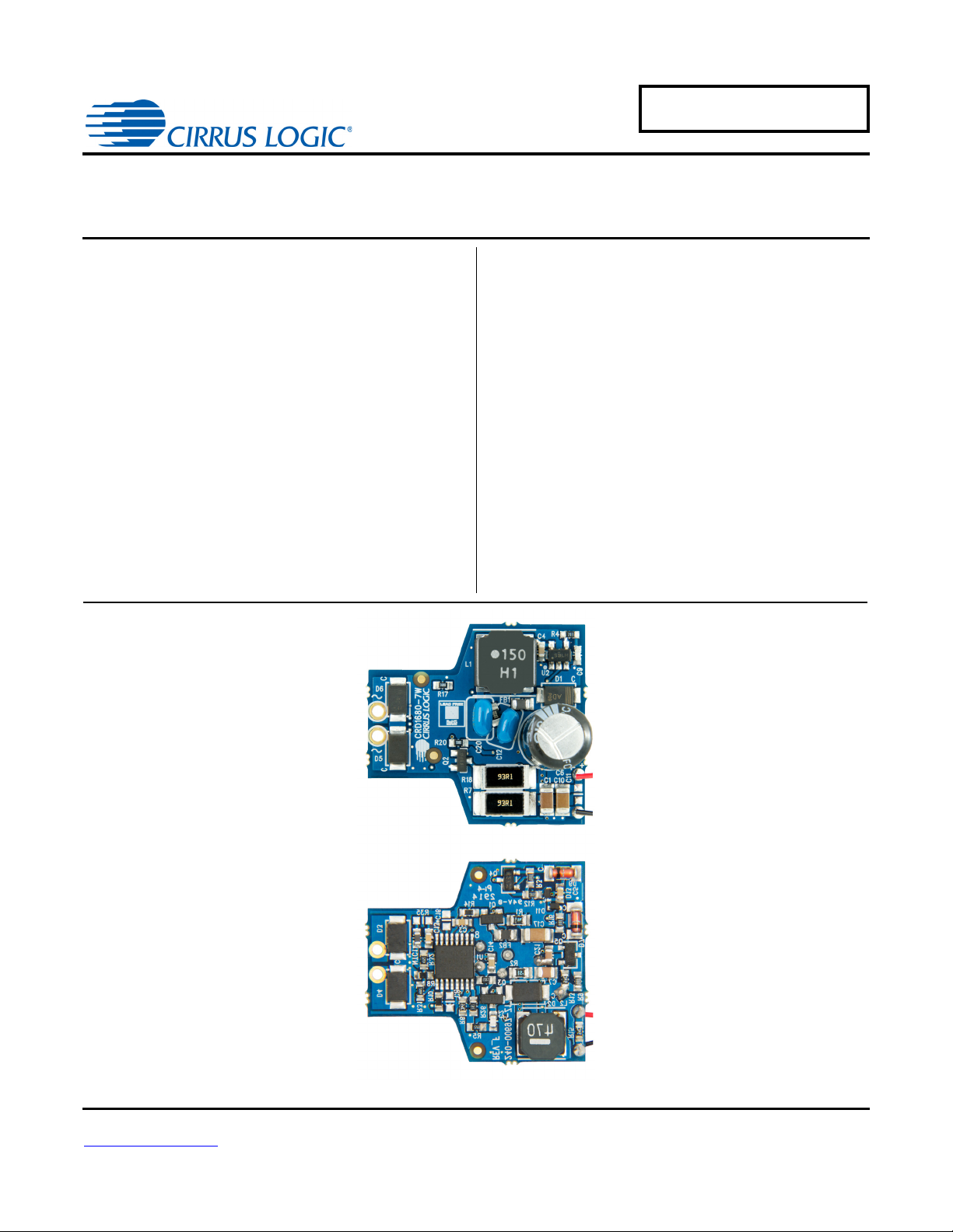
Top
Bottom
CRD1680-7W
1.102 28mm1.024 26mm0.672 17mm
7 Watt Reference Design
CRD1680-7W
Features
• Constant-current Output
• Flicker-free Dimming
• Line Voltage 12VAC/VDC, ±10%
• Rated Input Power: 7.0 W
• Rated Output Power: 5.6W
• Output Voltage: <15 V
• High Efficiency with Magnetic and Electronic
Transformers
• Low Component Count
• Supports Cirrus Logic Product CS1680
General Description
The CRD1680-7W reference design demonstrates the
performance of the CS1680 dimmable LED driver for
low-voltage lighting with a target output of 430mA driving
4LEDs in series
and multi-lamp transformer compatibility for non-dimmer
systems and dimmer systems paired with electronic and
magnetic low-voltage transformers
targeted to fit into MR16 LED lamp applications.
DIMENSIONS (OVERALL)
Length Width Height
For more information, see Figure 3 on page 6.
ORDERING INFORMATION
CRD1680-7W-Z 7 Watt Reference Design Supports CS1680
. It
provides exceptional single-lamp
. The form factor is
Cirrus Logic, Inc.
http://www.cirrus.com
Copyright Cirrus Logic, Inc. 2014
(All Rights Reserved)
AUG‘14
DS1017RD3
Page 2
CRD1680-7W
IMPORTANT SAFETY INSTRUCTIONS
ead and follow all safety instructions prior to using this demonstration board.
his Engineering Evaluation Unit or Demonstration Board must only be used for assessing IC performance in a
aboratory setting. This product is not intended for any other use or incorporation into products for sale.
his product must only be used by qualified technicians or professionals who are trained in the safety procedures
ssociated with the use of demonstration boards.
Risk of Electric Shock
The open and unprotected boards present a serious risk of electric shock and can cause serious injury or death.
Extreme caution needs to be exercised while handling this board.
Avoid contact with the exposed conductor or terminals of components on the board. High voltage is present on
exposed conductor and terminals of any components.
Dangerous voltages and/or currents may be internally generated and accessible at various points across the board.
Charged capacitors store high voltage, even after the circuit has been disconnected from the power source.
Make sure that the power source is off before wiring any connection. Make sure that all connectors are well
connected before the power source is on.
Follow all laboratory safety procedures established by your employer and relevant safety regulations and guidelines
such as the ones listed under, OSHA General Industry Regulations - Subpart S and NFPA 70E.
Suitable eye protection must be worn when working with or around demonstration boards. Always
omply with your employer’s policies regarding the use of personal protective equipment.
All components and metallic parts may be extremely hot to touch when electrically active.
Contacting Cirrus Logic Support
For all product questions and inquiries contact a Cirrus Logic Sales Representative. To find the one nearest to you
go to www.cirrus.com
IMPORTANT NOTICE
Cirrus Logic, Inc. and its subsidiaries ("Cirrus") believe that the information contained in this document is accurate and reliable. However, the information is subject
to change without notice and is provided "AS IS" without warranty of any kind (express or implied). Customers are advised to obtain the latest version of relevant
information to verify, before placing orders, that information being relied on is current and complete. All products are sold subject to the terms and conditions of sale
supplied at the time of order acknowledgment, including those pertaining to warranty, indemnification, and limitation of liability. No responsibility is assumed by Cirrus
for the use of this information, including use of this information as the basis for manufacture or sale of any items, or for infringement of patents or other rights of third
parties. This document is the property of Cirrus and by furnishing this information, Cirrus grants no license, express or implied under any patents, mask work rights,
copyrights, trademarks, trade secrets or other intellectual property rights. Cirrus owns the copyrights associated with the information contained herein and gives
consent for copies to be made of the information only for use within your organization with respect to Cirrus integrated circuits or other products of Cirrus. This consent does not extend to other copying such as copying for general distribution, advertising or promotional purposes, or for creating any work for resale.
CERTAIN APPLICATIONS USING SEMICONDUCTOR PRODUCTS MAY INVOLVE POTENTIAL RISKS OF DEATH, PERSONAL INJURY, OR SEVERE PROPERTY OR ENVIRONMENTAL DAMAGE ("CRITICAL APPLICATIONS"). CIRRUS PRODUCTS ARE NOT DESIGNED, AUTHORIZED OR WARRANTED FOR
USE IN PRODUCTS SURGICALLY IMPLANTED INTO THE BODY, AUTOMOTIVE SAFETY OR SECURITY DEVICES, LIFE SUPPORT PRODUCTS OR OTHER
CRITICAL APPLICATIONS. INCLUSION OF CIRRUS PRODUCTS IN SUCH APPLICATIONS IS UNDERSTOOD TO BE FULLY AT THE CUSTOMER'S RISK
AND CIRRUS DISCLAIMS AND MAKES NO WARRANTY, EXPRESS, STATUTORY OR IMPLIED, INCLUDING THE IMPLIED WARRANTIES OF MERCHANTABILITY AND FITNESS FOR PARTICULAR PURPOSE, WITH REGARD TO ANY CIRRUS PRODUCT THAT IS USED IN SUCH A MANNER. IF THE CUSTOMER
OR CUSTOMER'S CUSTOMER USES OR PERMITS THE USE OF CIRRUS PRODUCTS IN CRITICAL APPLICATIONS, CUSTOMER AGREES, BY SUCH USE,
TO FULLY INDEMNIFY CIRRUS, ITS OFFICERS, DIRECTORS, EMPLOYEES, DISTRIBUTORS AND OTHER AGENTS FROM ANY AND ALL LIABILITY, INCLUDING ATTORNEYS' FEES AND COSTS, THAT MAY RESULT FROM OR ARISE IN CONNECTION WITH THESE USES.
Cirrus Logic, Cirrus, the Cirrus Logic logo designs, EXL Core, and the EXL Core logo design are trademarks of Cirrus Logic, Inc. All other brand and product names
in this document may be trademarks or service marks of their respective owners.
R
T
l
T
a
x
x
x
x
x
x
c
2 DS1017RD3
,
Page 3

CRD1680-7W
1. INTRODUCTION
The CS1680 is a cascade boost-buck dimmable LED controller IC. The CS1680 uses a Cirrus Logic proprietary intelligent digital control that provides exceptional single-lamp and multi-lamp transformer compatibility for nondimmer systems and dimmer systems paired with electronic and magnetic low-voltage transformers. The CS1680
integrates a continuous conduction mode (CCM) boost converter that provides transformer compatibility and dimmer
compatibility with a constant output current buck stage. An adaptive digital algorithm controls the boost stage and
dimmer compatibility operation mode to enable flicker-free operation down to 5% output current with leading-edge
and trailing-edge dimmers. For in-depth implementation of the CS1680, please consult documents in Further Reading on page 3 for IC and reference design details.
The CRD1680-7W board is optimized to deliver low system cost in a high-efficiency, flicker-free, phase-dimmable,
solid-state lighting (SSL) solution for incandescent lamp replacement applications. The feedback loop is closed
through an integrated digital control system within the IC. Protection algorithms such as output open/ short, overcurrent detection, boost overvoltage, and overtemperature thermistors protect the system during abnormal conditions.
Details of these features are provided in the CS1680 Dimmable LED Driver IC for Low-voltage Lighting data sheet.
The CRD1680-7W board demonstrates the performance of the CS1680. This reference board has been designed
for an output load of 4
This document provides the schematic for the board. It includes oscilloscope screen shots that indicate various operating waveforms. Graphs are also provided that document the performance of the board in terms of Efficiency vs.
Line Voltage, Output Current vs. Line Voltage, and Output Current vs. Dim Angle for the CS1680 dimmable LED
controller IC.
LEDs in series at a target output current of 430mA (12.0V typical).
Extreme caution needs to be exercised while handling this board. This board is to be used by trained professionals
only.
Further Reading
• Cirrus Logic, 2014. “Dimmable LED Driver IC for Low-voltage Lighting,” DS1055F1, AUG 2014.
• Cirrus Logic, 2014. “Design Guide for a CS1680 Dimmable LED Driver IC for Low-voltage Lighting,”
AN379REV3, AUG 2014.
NOTE
If any other Cirrus Logic document contains information conflicting with the device data sheet,
the device data sheet is considered to have the most current and correct data.
DS1017RD3 3
Page 4
600-00697-Z1 REV_F1
D.PAPANDREA/JDG D.PAPANDREA
SHEET
OFSHEET
ENGINEER
DATE
DRAWN BY
PART #
SHEET
8/14/2014
CRD1680-7W-Z
11
TITLE
SIZE
B
08/07/13INITIAL RELEASEA.0
DATEDESCRIPTIONREV
C20 now Throug h Hole
1127 B.1
ADDED RED AND BLACK WIRES 09/10/13
B.2 10/08/13Changing the silicon to B1 and some components values
1136
C.0 11-19-13ADDED R11 & C12
1153
1165
D.0 ADDED R12 & R16. CHANGED D11/D13,U2,R11,C12 12/16/13
1194
E.0 change C12 from SMD0805 To through hole TDK FK16X7R1H105K 03/11/14
VIN+
VIN-
1225
F CHANGES TO COMPLY WITH RADIATED EMI 07/11/14
LED OUTPUT
LED OUTPUT
1235
F1 C HANGED FB1,FB2 AND R102 08/12/14
-t
NTC1 100K
0.1mA
12
D3
PMEG4050EP,115
40V
12
D4
PMEG4050EP,115
40V
12
D6
PMEG4050EP,115
40V
12
D5
PMEG4050EP,115
40V
12
D1
PMEG4020EP,115
40V
12
D2
PMEG4020EP,115
40V
L1
15uH
1
G
2
S
3
D
Q1
IRLML0040TRPBF
R1
0.16 Ohm
R2
0.51 Ohm
R14
22 OHM
R17
10
R20
10
C16
NO POP
0603
C8
NO POP
0603
C6
180uF
ELEC
35V
L2
47uH
1
CTRL2
2
EOTP
3
BSTSENSE
4
GND
5
BSTGD
6
VDD
7
GPIO
8
NC
9
BUCKZCD
10
NC
11
CLAMP
12
BUCKGD
13
BUCKSENSE
14
VAC
15
BSTOUT
16
CTRL1
U1
CS1680-FZZ TSSOP16
1
G
2
S
3
D
Q3
IRLML0040TRPBF
C13
1000pF
X7R
R35
NO POP
1
B
2
E
3
C
Q4
PMBT4401,215
L
N
+
-
R3
5.11K
12
D9
BZV55-C6V2,115
12
D7
BZV55-C16,115
C4
0.10uF
X7R
R4
20K
12
D13
BAS52-02V H6327
45V
12
D11
BAS52-02V H6327
45V
1
B
2
E
3
C
Q5
PMBT4401,215
R13
35.7K
R26
2K
R10
604K
R8
604K
R7
93.1
1
G
2
S
3
D
Q2
IRLML0040TRPBF
R5
6.65K
R6
35.7K
C2 27pF
COG
R15
35.7K
C10
10uF
X7R
C7
4.7uF
X7R
R9
0
C3
0.10uF
X7R
C21
1uF
X7R
C9
100pF
COG
C20
0.68UF
MLCC
R31
49.9K
R32
47.5K
C5
0.10uF
X7R
C1
10uF
X7R
C11
NO POP
0603
FB1
120OHM@100MHz
PCB DWG-
240-00697-Z1
ASSY DWG-
603-00697-Z1
SCHEMATIC DWG
600-00697-Z1
LBL SUBASSY PROD ID AND REV
WIRE-RED-STR-28AWG
080-00043-Z1
WIRE-BLACK-STR-28AWG
080-00044-Z1
R11
1
C12
1UF
MLCC
R1251.1
R160
1
NC
2
A
3
GND
4
Y
5
VCC
U2
SN74LVC1G14MDBVREP
FB2
120OHM@100MHz
C17
10uF
X7R
C14
0.10uF
X7R
R10222 OHM
R18
93.1
4 DS1017RD3
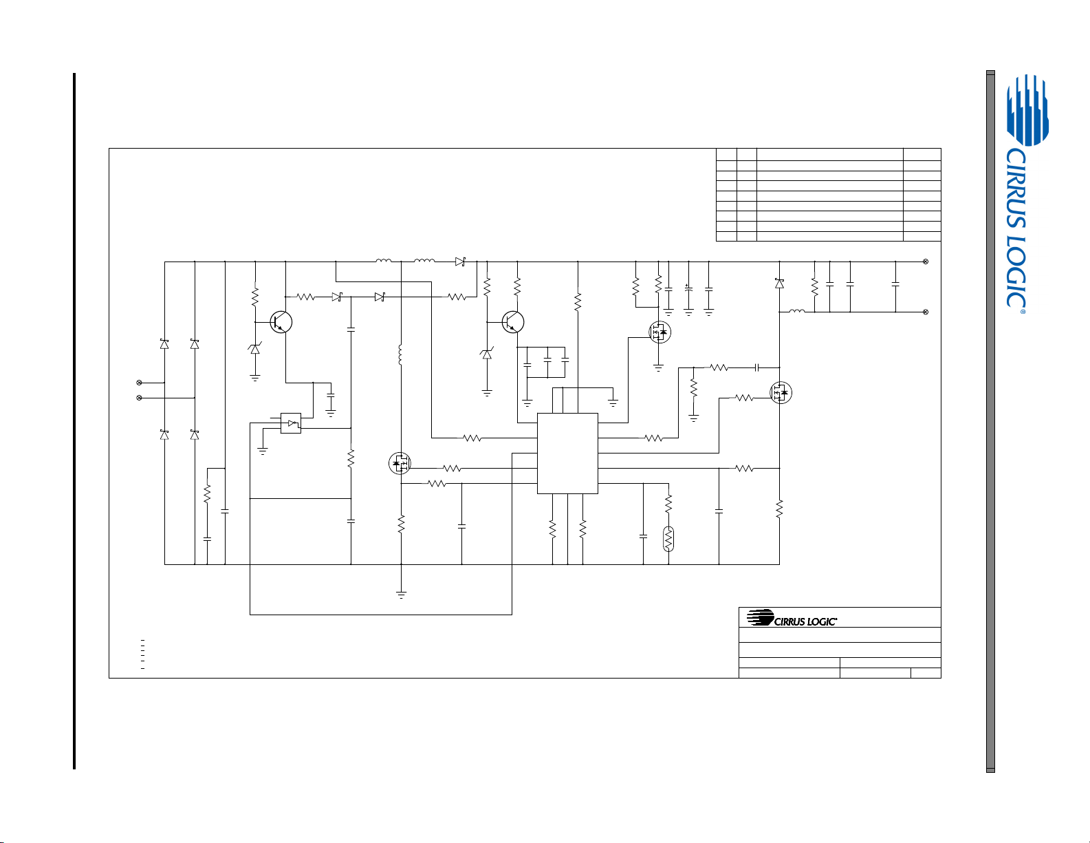
2. SCHEMATIC
CRD1680-7W
Figure 1. Schematic
Page 5
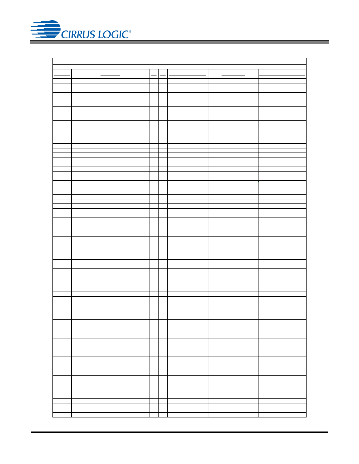
3. BILL OF MATERIALS
Line Ite m Descri ption Qty UM Reference Designator Manufacturer Manufacturer Part Number
0002 CAP 10uF ±10% 25V X7R NPb 1206 2
C1 C10
0003 CAP 27pF ±5% 50V C0G NPb 0603 1 EA
C2
KEMET
C0603C270J5GAC
0004 CAP 0.10uF 10% 25V X7RLESR NPb 0603 4
C3 C4 C5 C14
0005 CAP 180uF ±20% 35V AL ELEC NPb RA D 1 EA
C6
PANASONIC
EEUFR1V 181B
0006 CAP 4.7uF ±10% 35V X7R NPb 0805 1
C7
0008 CAP 100pF ±5% 50V C0G NPb 0603 1 EA
C9
KEMET
C0603C101J5GAC
0009 CAP 1uF ±10% 50V X7R NPb RAD 1
C12
0010 CAP 1000pF ±10% 50V X7R NPb 0603 1 EA
C13
KEMET
KOA
PANASONIC
C0603C102K5RAC
X7R0603HTTD102K
ECJ1VB1H102K
0011 CAP 10uF ±10% 35V X7R MLC NPb 1206 1
C17
0012 CAP 0.68uF ±10% 50V X7R NPb RAD 1
C20
0013 CAP 1uF ±10% 25V X7R CER NPb 0603 1
C21
0014 DIODE SKY BARR 2A 40V NPb SOD128 2
D1 D2
0015 DIODE SKY BARR 5A 40V NPb SOD128 4
D3 D4 D5 D6
0016 DIODE ZENER 500mW 16V NPb SOD80C 1
D7
0017 DIODE ZENER 500mW 6.2V NPb S OD80C 1
D9
0018 DIODE SHKY 750mA 45V NPb SC79-2 2
D11 D13
0019 FE BEAD 3.0A 120ohm@100MHz NPb 0805 2
FB1 FB2
0021 IND PWR 15uH 2.4A ±20% SHLD NPb SM 1
L1
0022 IND PWR 47uH 1.3A ±20% SHLD NPb SM 1
L2
0023 THERM 100K OHM ±5% 0.10mA NPb 0603 1
NTC1
0024 TRAN MOSF ET N-CH 40V 3.6A NPb SOT23 3
Q1 Q2 Q3
0025 TRAN NPN SW 40V 600mA NP b SOT-23 2
Q4 Q5
0026 RES 0.16 OHM 1/ 4W ±1% NP b 0805 1
R1
0027 RES 0.51 OHM 1/ 4W ±1% NP b 0805 1
R2
0028 RES 5.11k OHM 1/10W ±1% NPb 0603 1 EA
R3
DALE
KOA
PANASONIC
CRCW06035K 11FKEA
RK73H1JTTD5111F
ERJ3EKF5111V
0029 RES 20k OHM 1/ 10W ±5% NP b 0603 FILM 1 EA
R4
DALE
KOA
CRCW060320K 0JNEA
RK73B1JTTD203J
0030 RES 6.65k OHM 1/10W ±1% NPb 0603 1
R5
0031 RES 35.7K OHM 1/10W ±1% NPb 0603 3
R6 R13 R15
0032 RES 93.1 OHM 1W ±1% FILM NPb 2512 2
R7 R18
0033 RES 604K OHM 1/ 10W ±1% NPb 0603 2
R8 R10
0034 RES 0 OHM 1/10W ±5% NPb 0603 FILM 2 EA
R9 R16
NIC COMPO NENTS
PANASONIC
VENKEL
NRC0606ZOTRF
ERJ3EKF0R00V
CR0603-10W-000T
0035 RES 1 OHM 1/4W ±1% NPb 0805 1
R11
0036 RES 51.1 OHM 1/ 10W±1% NP b 0603 FILM 1 EA
R12
KOA
PANASONIC
RK73H1JTTD51R1F
ERJ3EKF51R1V
0037 RES 22.0 OHM 1/ 10W ±1% NP b 0603 2
R14 R102
0038 RES 10 OHM 1/10W ±1% NPb 0603 FILM 2 EA
R17 R20
VENKEL
PANASONIC
C0603-10W-10R0FT
ERJ3EKF10R0V
0039 RES 2k OHM 1/ 10W ±5% NP b 0603 FILM 1 EA
R26
KOA
PANASONIC
RK73B1JTTD202J
ERJ3GEYJ202V
0040 RES 49.9k OHM 1/10W ±1% NPb 0603 1 EA
R31
KOA
PANASONIC
RK73H1JTTD4992F
ERJ3EKF4992V
0041 RES 47.5k OHM 1/10W ±1% NPb 0603 1 EA
R32
KOA
PANASONIC
RK73H1JTTD4752F
ERJ3EKF4752V
0043 IC CRUS TRIAC DIM LV 12V NPb TSOP 16 1
U1
0044 IC INV SNGL SCHMIT-TRIG NPb SOT23-5 1
U2
0045 WIRE 28AW G PTFE INSULATED STRND RED 3 IN W 1 A NY SOURCE 080-00043-Z1
0046 WIRE 28AW G PTFE INSUL STRND BLACK 3 IN W 2
Figure 2. Bill of Materials
Date Gene rated: 08/14/2014
CRD1680-7W
BOM: CRD1680-7W-Z Rev: F1
EA
EA
EA
EA
EA
EA
EA
EA
EA
EA
EA
EA
EA
EA
EA
EA
EA
EA
EA
EA
EA
EA
EA
EA
EA
EA
EA
EA
TAIYO YUDEN TMK316B7106KL-TD
NIC COMPONENTS
MURATA GRM188R71E104KA01D
PANASONIC
TDK C2012X7R1V475K125AC
Walsin
TDK FK16X7R1H105K
NIC COMPONENTS
TAIYO YUDEN GMK316AB 7106KL-TR
TDK FK16X7R1H684K
TDK CGA3E1X7R1E105K080A C
NXP PMEG4020EP,115
NXP PMEG4050EP,115
NXP BZV55-C16,115
NXP BZV55-C6V2,115
INFINEON BAS 52-02V H6327
WURTH ELECTRONICS 742792023
TAIYO YUDEN NRS8040T150MJGJ
TAIYO YUDEN NR6045T470M
MURATA NCP18WF104J03RB
INTERNATIONAL RECTIFIER IRLML0040TRPBF
NXP PMBT4401,215
PANASONIC ERJS6SFR16V
PANASONIC ERJS6QFR51V
WALSIN
PANASONIC
DALE CRCW06036K65FKEA
YAGE O RC0603FR-0735K7L
ROHM MCR100JZHF93R1
YAGE O RC0603FR-07604KL
DALE
WALSIN
STACK POLE RNCP0805FTD1R00
DALE
VENKEL
PANASONIC ERJ3EKF22R0V
DALE
WALSIN
DALE
WALSIN
DALE
WALSIN
DALE
WALSIN
CIRRUS LOGIC CS1680-FZZ/B1
TEXAS INSTRUMENTS SN74LV C1G14MDBVREP
ANY S OURCE 080-00044-Z1
NMC0603NPO270J50TRPF
EEUFR1V 181
0603N101J500LT
NMC0603X7R102K50TRPF
WR06X5111FTL
ERJ3GEYJ203V
CRCW06030000Z0EA
WR06X000PTL
CRCW060351R1FK EA
CR0603-10W-51R1FT
CRCW060310R0FK EA
ER06X10R0FTL
CRCW06032K 00JNEA
WR06X202JTL
CRCW060349K 9FKEA
WR06X4992FTL
CRCW060347K 5FKEA
WR06X4752FTL
DS1017RD3 5
Page 6
6 DS1017RD3
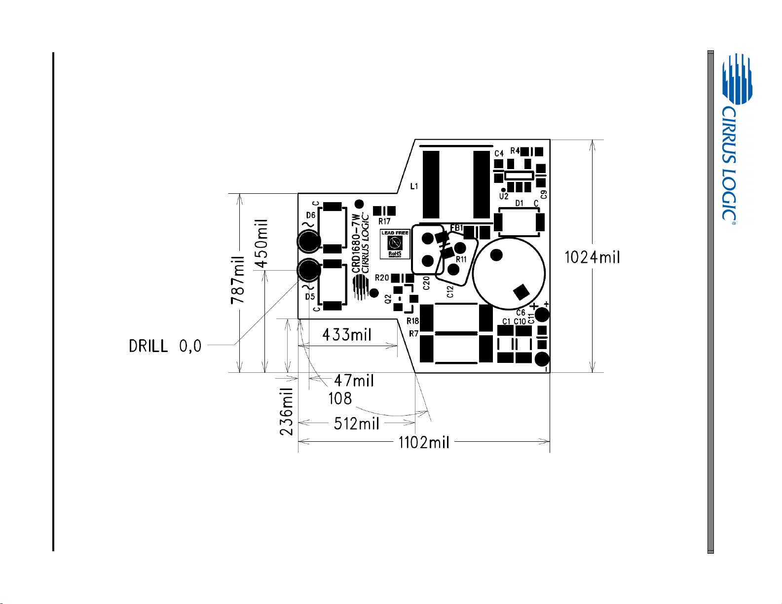
4. BOARD LAYOUT
Figure 3. PCB Dimensions
CRD1680-7W
Page 7
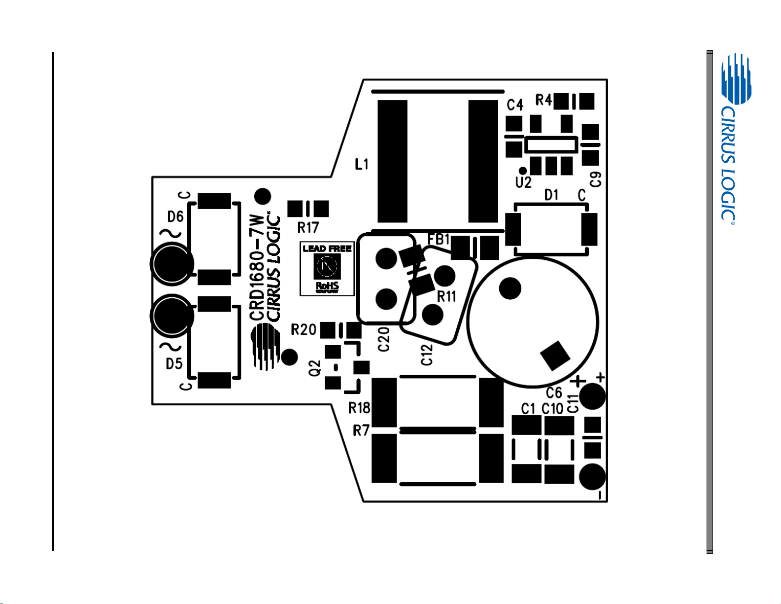
DS1017RD3 7
Figure 4. Top Silkscreen
CRD1680-7W
Page 8
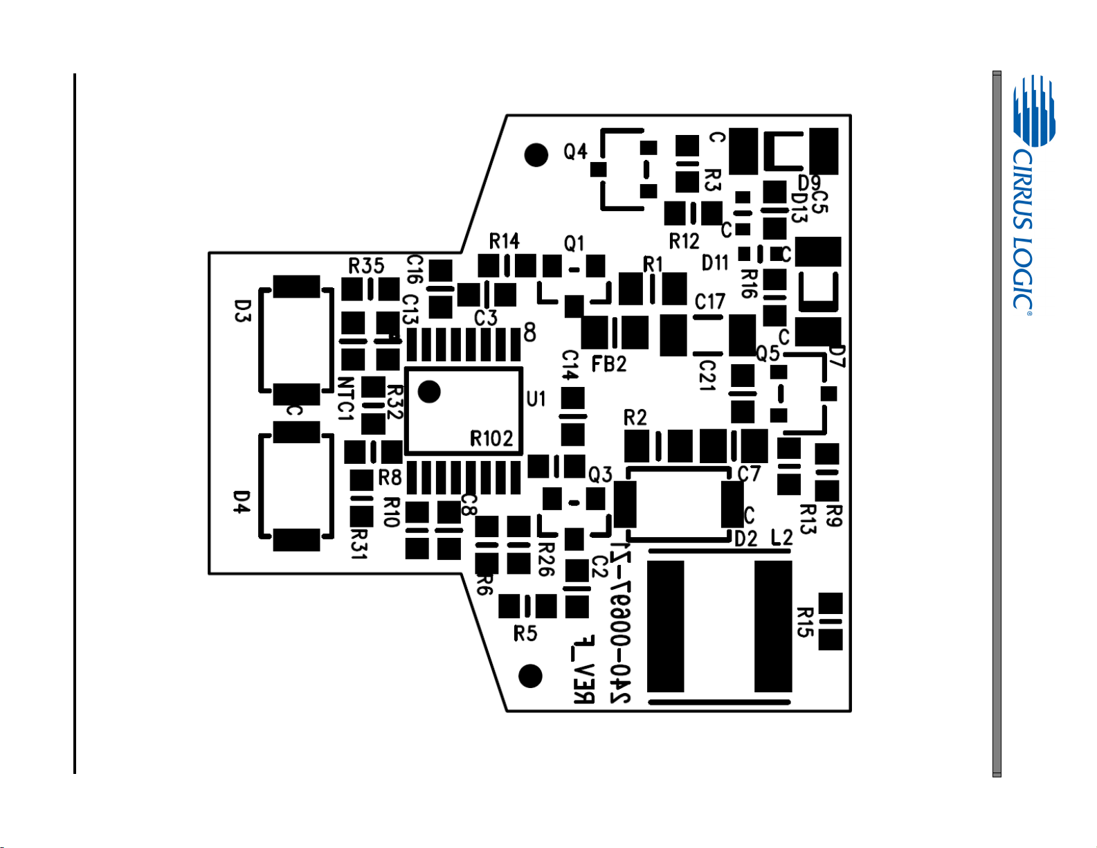
8 DS1017RD3
Figure 5. Bottom Silkscreen
CRD1680-7W
Page 9
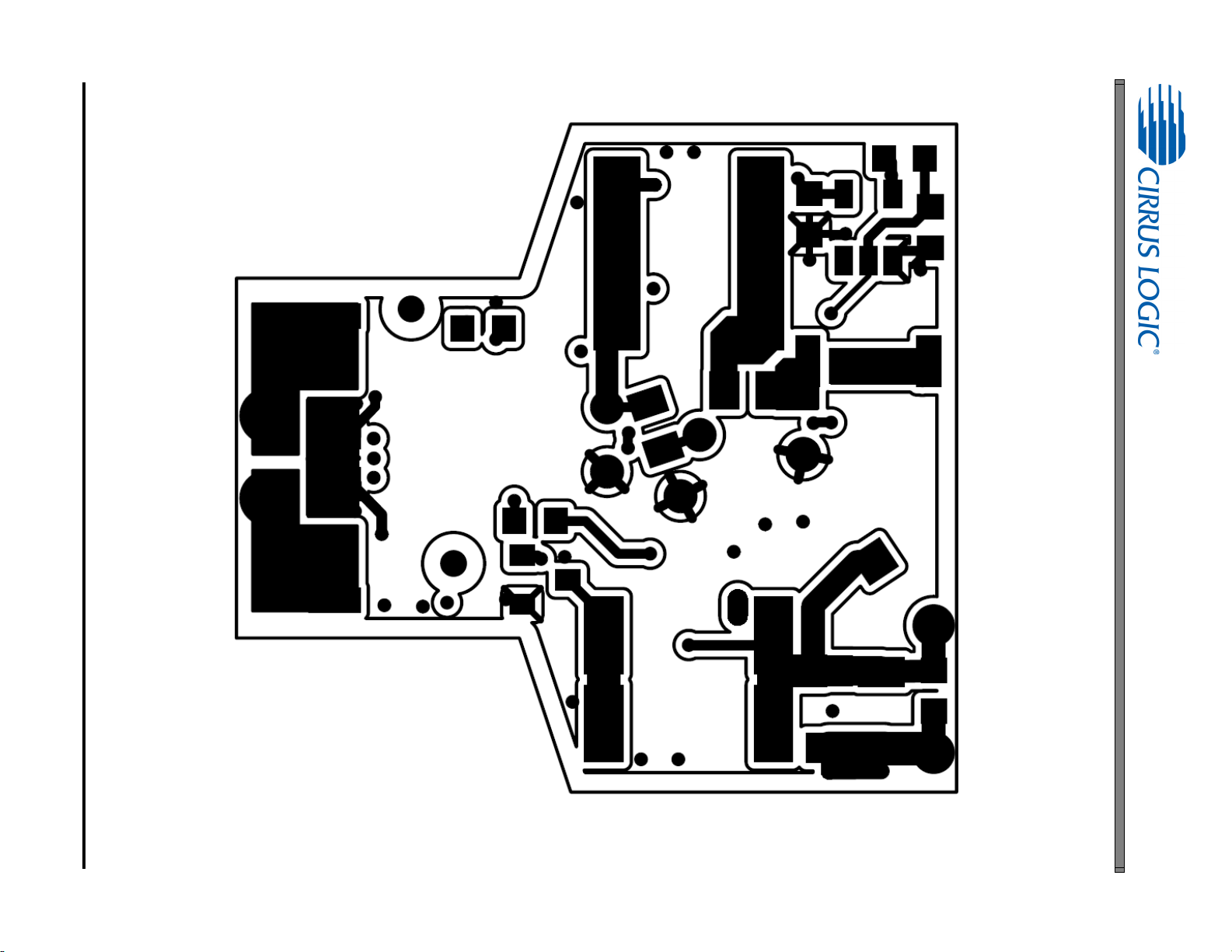
DS1017RD3 9
Figure 6. Top Routing, Layer 1
CRD1680-7W
Page 10
10 DS1017RD3
Figure 7. Power Plane, Layer 2
CRD1680-7W
Page 11

DS1017RD3 11
Figure 8. Ground Plane, Layer 3
CRD1680-7W
Page 12

12 DS1017RD3
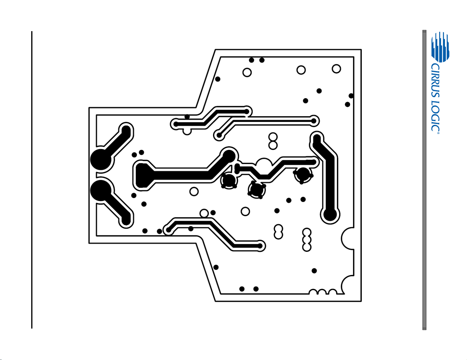
Figure 9. Bottom Routing, Layer 4
CRD1680-7W
Page 13

5. THERMAL IMAGING
Figure 10. Top Thermal
Figure 11. Bottom Thermal
CRD1680-7W
DS1017RD3 13
Page 14

CRD1680-7W
6. DIMMER COMPATIBILITY
The boost stage is a low-side asynchronous boost converter. Once the CS1680 reaches its UVLO start threshold
and begins normal operation, the CS1680 controller executes a dimmer switch detection algorithm to set the operating state of the IC. Table 1 summarizes the system operating state that produced the empirical dimmer compatibility results.
MR16 Lamp with a CS1680 (12VAC)
Date 09/09/2013 Power Factor
Vendor Cirrus Logic IEC-61000-3-2 Compliant (Y/N)
Input Voltage (RMS) 12 EN55015 Compliant (Y/N) Y
Form Factor MR16 Nominal Input Power (W)
Model # CRD1680-7W Maximum Input Power (W)
IC CS1680 Output Voltage (V)
Topology Boost/Buck Output Current (mA)
Isolation (Y/N) N
Efficiency
7
(%) 76.6 % Output Power (W)
Output Current Ripple
1,6
1,4
1,4
120Hz (mA)
1,6
1,6
2,6
3,6
1,5
0.98
Y
6.79
7.0
12.27
424
0
5.21
Notes: 1. Tested at nominal input voltage, nominal input frequency and without a dimmer
2. Tested over input voltage tolerances for steady-state operation
3. Compliant with IEC 61000-3-2 Class C < 25 W
4. Average
5. Peak-to-peak
6. Measured with Chroma 66202 Power Analyzer
7. MR16 lamp efficiency is dependent on LED output voltage V
OUT
14 DS1017RD3
Page 15

DS1017RD3 15
6.1 120VAC Dimmer Compatibility
Table 1 reports the empirical dimmer compatibility results when detectable inputs to the dimmer compatibility circuit are generated using a 120VAC
transformer paired with a leading-edge or trailing-edge dimmer.
Table 1: 120VAC, 60Hz Mains Power System
Dimmer
1
Transformer
Lutron DVLV-600P
Leading Edge
Flicker Free2
Steady-State
# of lamps # of lamps # of lamps # of lamps # of lamps # of lamps # of lamps # of lamps
3
I
out
(%)
Min
Max Max Max Max
Lutron DVELV-300P
Trailing Edge
Flicker Free2
Steady-State
I
out
(%)
Min
Flicker Free2
Steady-State
Lutron SELV-300P
Trailing Edge
I
(%)
out
Min
Flicker Free2
Steady-State
Levitron 6615
Trailing Edge
I
(%)
out
Min
136 1 3 6 136 1 3 6 136 1 3 6 136 1 3 6
Hatch
LS1250EN
Lightech
LET60
Hatch
RS12-80M
Hatch
VS12-60WD
Osram
ET-MZ 60
YYY
YYY
YYY
YYY
YYN
Eurofase Y N N
5.2 5.2 5.2
---
808070 --- --- ---
5.2 5.2 5.2
YYY
100 100 100 100 100 90 100 100 80 100 100 100
5.2 5.2 5.2
YYY
100 100 100 100 100 100 100 100 80 100 100 100
5.2 5.2 5.2
YYY
100 100 100 100 100 80 100 90 80 100 100 90
5.2 5.2 5.2
YYY
100 100 100 100 100 70 100 90 70 100 100 80
5.2 5.2 5.2
YYN
---
5.2 5.2 5.2
5.2 5.2 5.2
5.2 5.2 5.2
5.2 5.2 5.2
5.2 5.2 5.2
---
YYY
YYY
YYY
YYY
YYY
---
5.2 5.2 5.2
5.2 5.2 5.2
5.2 5.2 5.2
5.2 5.2 5.2
5.2 5.2 5.2
---
---
20 10 5.2
YYY
30 10 10
YYY
10 5.2 5.2
YYY
10 5.2 5.2
YYY
10 10 10
YYN
100 90 70 100 100 80 100 100 70 100 100 90
Notes: 1. This document includes trademarks, trade names, brands, logos, product names and/or product identifiers of companies other than Cirrus Logic, Inc. All such trademarks,
trade names, brands, logos, product names, and product identifiers are for identification purposes only and are the property of their respective owners, who are not
affiliated with Cirrus Logic. Please visit the respective sites of those owners to obtain a listing or understanding of their trademark rights. This document also includes
results from testing performed by Cirrus Logic for its own purposes and for which there are currently no industry standards. While this testing was applied objectively, its
results may include at least some degree of subjectivity. The testing or test results should not be interpreted as any comment on the overall quality or suitability of any
tested products.
2. Flicker-free results are reported at different conduction angle ranges and dependent on transformer and dimmer pairing.
3. Empirical results are recorded only with a magnetic transformer paired with a lead-edge dimmer.
CRD1680-7W
Page 16

16 DS1017RD3
6.2 230VAC Dimmer Compatibility
Table 2 reports the empirical dimmer compatibility results when detectable inputs to the dimmer compatibility circuit are generated using a 230VAC
transformer paired with a leading-edge or trailing-edge dimmer.
Table 2: 230VAC, 50Hz Mains Power System
Dimmer
1
Transformer
HPM CAT400L
Leading Edge
Flicker Free2
Steady-State
# of lamps # of lamps # of lamps # of lamps # of lamps # of lamps # of lamps # of lamps
3
I
out
(%)
Min
Flicker Free2
Steady-State
Max Max Max Max
Busch 2247U
Leading Edge
I
(%)
out
Min
Flicker Free2
Steady-State
HPM CAT400T
Trailing Edge
I
(%)
out
Min
Flicker Free2
Steady-State
Clipsal 32E450TM
Trailing Edge
I
(%)
out
Min
136 1 3 6 136 1 3 6 136 1 3 6 136 1 3 6
Niko
320-00001
Osram
Parrot 105
Philips
S60
Primaline
105
Tridonic
Possum
Notes: 1. This document includes trademarks, trade names, brands, logos, product names and/or product identifiers of companies other than Cirrus Logic, Inc. All such trademarks,
2. Flicker-free results are reported at different conduction angle ranges and dependent on transformer and dimmer pairing.
3. Empirical results are recorded only with a magnetic transformer paired with a lead-edge dimmer.
YYY
YYY
YYY
YYY
YYY
trade names, brands, logos, product names, and product identifiers are for identification purposes only and are the property of their respective owners, who are not
affiliated with Cirrus Logic. Please visit the respective sites of those owners to obtain a listing or understanding of their trademark rights. This document also includes
results from testing performed by Cirrus Logic for its own purposes and for which there are currently no industry standards. While this testing was applied objectively, its
results may include at least some degree of subjectivity. The testing or test results should not be interpreted as any comment on the overall quality or suitability of any
tested products.
5.2 5.2 5.2
YYY
100 90 100 100 100 100 -
5.2 5.2 5.2
YYY
100 100 40 100 100 80 80 80 60 100 100 80
5.2 5.2 5.2
YNY
100 90 80 100 100 100 100 90 80 100 100 100
5.2 5.2 5.2
YYN
100 100 90 100 100 40 100 80 90 100 100 100
5.2 5.2 5.2
NYY
100 100 80 100 100 100 80 70 60 100 100 60
5.2 5.2 5.2
5.2 5.2 5.2
5.2 5.2 5.2
5.2 5.2 5.2
5.2 5.2 5.2
---
YYN
YYY
YYY
YYN
5.2 5.2 5.2
5.2 5.2 5.2
5.2 5.2 5.2
5.2 5.2 5.2
-
--
--
---
YYY
YYY
YYY
YYY
5.2 5.2 5.2
5.2 5.2 5.2
5.2 5.2 5.2
5.2 5.2 5.2
-
-
--
--
CRD1680-7W
Page 17

CRD1680-7W
7. INDUCTOR CONSTRUCTION
The CS1680 integrates a continuous conduction mode (CCM) boost converter that provides transformer compatibility and dimmer compatibility with a constant output current buck stage. The following sections describe the boost
and buck inductors installed on the CRD1680-7W.
7.1 Boost Inductor
The CS1680 uses an adaptive digital algorithm to control the boost stage and dimmer compatibility operation mode,
which enables flicker-free operation down to 5% output current with leading-edge and trailing-edge dimmers. Boost
inductor L1 is selected to be a standard TAIYO YUDEN power inductor.
7.1.1 Electrical Specifications
Characteristics conditions:
• Operating temperature range: -25 °C to +125 °C (including coil heat)
Parameter Condition Symbol Value Unit
TAIYO YUDEN Boost Inductor # NRS8040T150MJGJ
Inductance (Note 1)
DC Resistance (Note 1)
Saturation Current
f
=100kHz
measured
Maximum
Rated Current
15 (±20%) H
0.065
2900 mA
Notes: 1. Measured across pins 1 and 2
7.2 Buck Inductor
The CS1680 buck stage is a constant current-regulated DC-DC converter capable of delivering the highest possible
efficiency with constant current output while minimizing line frequency ripple. Buck inductor L2 is selected to be a
standard TAIYO YUDEN power inductor.
7.2.1 Electrical Specifications
Characteristics conditions:
• Operating temperature range: -25 °C to +125 °C (including coil heat)
Parameter Condition Symbol Value Unit
TAIYO YUDEN Buck Inductor #NR6045T470M
Inductance (Note 1)
DC Resistance (Note 1)
Saturation Current
Notes: 1. Measured across pins 1 and 2
f
=100kHz
measured
t
=20°C
DCR
Rated Current
47 (±20%) H
0.286
1300 mA
DS1017RD3 17
Page 18

8. PERFORMANCE PLOTS (120VAC)
0
0.1
0.2
0.3
0.4
0.5
20 40 60 80 100 120 140 160 180
Output Current (A)
Dim Angle (o)
Mode 1
Mode 1 - Hatch LS1250EN w/Leading-edge Waveform
Mode 2 - Lightech LET60 w/
Traili
ng-edge Waveform
Mode 3 - Lightech LET60 w/Leading-edge Waveform
Mode 3
Mode 2
Mode 1
Mode 3
Mode 2
Figure 12. Typical CRD1680-7W Output Current vs. Dim Angle, 120VAC
0
2
4
6
8
10
12
20 40 60 80 100 120 140 160 180
Input Power (W)
Dim Angle (o)
Mode 1 - Hatch LS1250EN w/Leading-edge Waveform
Mode 2 - Lightech LET60 w/Trailing-edge W aveform
Mode 3 - Lightech LET60 w/Leading-edge Waveform
Mode 1
Mode 3
Mode 2
Figure 13. Typical CRD1680-7W Input Power vs. Dim Angle, 120VAC
CRD1680-7W
18 DS1017RD3
Page 19

CRD1680-7W
0.0
0.2
0.4
0.6
0.8
1.0
108 112 116 120 124 128 132
Output Current (A)
Line Voltage (V)
Magnetic Transformer - Hatch LS1250EN
Electronic Transformer - Lightech LET60
Magnetic Transformer
Electronic Transformer
Figure 14. CRD1680-7W Output Current vs. Line Voltage, 108VAC to 132VAC
60
65
70
75
80
85
90
108 112 116 120 124 128 132
Efficiency (%)
Line Voltage (V)
Magnetic Transformer - Hatch LS1250EN
Electronic Transformer - Lightech LET60
Magnetic Transformer
Electronic Transformer
Figure 15. Typical CRD1680-7W Efficiency vs. Line Voltage, 108VAC to 132VAC
DS1017RD3 19
Page 20

CRD1680-7W
0.60
0.65
0.70
0.75
0.80
0.85
0.90
0.95
1.00
108 112 116 120 124 128 132
Power Factor
Line Voltage (V)
Magnetic Transformer - Hatch LS1250EN
Electronic Transformer - Lightech LET60
Magnetic Transformer
Electronic Transformer
Figure 16. CRD1680-7W Power Factor vs. Line Voltage, 108VAC to 132 VAC
20 DS1017RD3
Page 21

CRD1680-7W
Figure 17. No-dimmer CRD1680-7W Output Mode1, Steady-state
Figure 18. Maximum CRD1680-7W Output Mode1, Steady-state
DS1017RD3 21
Page 22

CRD1680-7W
Figure 19. Maximum CRD1680-7W Output Mode2, Steady-state
Figure 20. Maximum CRD1680-7W Output Mode3, Steady-state
22 DS1017RD3
Page 23

CRD1680-7W
Figure 21. CRD1680-7W Output Current at Minimum Dim Angle, Mode1, Turn-on Waveforms
Figure 22. CRD1680-7W Output Current at Maximum Dim Angle, Mode1, Turn-on Waveforms
DS1017RD3 23
Page 24

CRD1680-7W
Figure 23. CRD1680-7W Output Current at Minimum Dim Angle, Mode2, Turn-on Waveforms
Figure 24. CRD1680-7W Output Current at Maximum Dim Angle, Mode2, Turn-on Waveforms
24 DS1017RD3
Page 25

CRD1680-7W
Figure 25. CRD1680-7W Output Current at Minimum Dim Angle, Mode3, Turn-on Waveforms
Figure 26. CRD1680-7W Output Current at Maximum Dim Angle, Mode3, Turn-on Waveforms
DS1017RD3 25
Page 26

9. PERFORMANCE PLOTS (230VAC)
0
0.1
0.2
0.3
0.4
0.5
20 40 60 80 100 120 140 160 180
Output Current (A)
Dim Angle (o)
Mode 1
Mode 1 - Niko 320-0001 w/Leading-edge Waveform
Mode 2 - Parrot 105 w/
Trailing-edge Waveform
Mode 3 - Parrot 105 w/Leading-edge Waveform
Mode 3
Mode 2
Figure 27. Typical CRD1680-7W Output Current vs. Dim Angle, 230VAC
0
2
4
6
8
10
12
20 40 60 80 100 120 140 160 180
Input Power (W)
Dim Angle (o)
Mode 1
Mode 1 - Niko 320-0001 w/Leading-edge Waveform
Mode 2 - Parrot 105 w/
Traili
ng-edge Waveform
Mode 3 - Parrot 105 w/Leading-edge Waveform
Mode 3
Mode 2
Figure 28. Typical CRD1680-7W Input Power vs. Dim Angle, 230VAC
CRD1680-7W
26 DS1017RD3
Page 27

CRD1680-7W
0.0
0.2
0.4
0.6
0.8
1.0
208 212 216 220 224 228 232 236 240 244 248 252
Output Current (A)
Line Voltage (V)
Magnetic Transformer - Niko 320-0001
Electronic Transformer - Parrot 105
Magnetic Transformer
Electronic Transformer
Figure 29. CRD1680-7W Output Current vs. Line Voltage, 208VAC to 252VAC
60
65
70
75
80
85
90
208212216220224228232236240244248252
Efficiency (%)
Line Voltage (V)
Magnetic Transformer - Niko 320-0001
Electronic Transformer - Parrot 105
Magnetic Transformer
Electronic Transformer
Figure 30. Typical CRD1680-7W Efficiency vs. Line Voltage, 208VAC to 252VAC
DS1017RD3 27
Page 28

CRD1680-7W
0.6
0.65
0.7
0.75
0.8
0.85
0.9
0.95
1
208 212 216 220 224 228 232 236 240 244 248 252
Power Factor
Line Voltage (V)
Magnetic Transformer - Niko 320-0001
Electronic Transformer - Parrot 105
Magnetic Transformer
Electronic Transformer
Figure 31. CRD1680-7W Power Factor vs. Line Voltage, 208VAC to 252 VAC
28 DS1017RD3
Page 29

10.CONDUCTED EMI
Figure 32. CRD1680-7W Conducted EMI
Device Under Test: CRD1680-7W-Z Operating Conditions: 230V 50Hz
Test Specification: IEC 61000-3-2 Operator Name: DLP
Scan Settings (1 Range)
Frequencies Receiver Settings
Start Stop Step Res BW M-Time Atten Preamp
150kHz 30MHz 4.5kHz 9 kHz (6dB) 50 ms Auto Off
Final Measurement
Detectors: PK+, AV Peaks: 8 Meas Time: 1s Acc. Margin: 12dB
CRD1680-7W
DS1017RD3 29
Page 30

11.RADIATED EMI
Figure 33. CRD1680-7W Radiated EMI - Horizontal Polarity
Figure 34. CRD1680-7W Radiated EMI - Vertical Polarity
Device Under Test: CRD1680-7W-Z Operator Name: DLP
Test Specification: CISPR 16-1-4:2007 EN55022 Compliant (Y/N): Y
Antenna Orientation: Horizontal/Vertical Frequency Range: 30MHz to 1GHz
EUT Line Voltage: 230 VAC EUT Power Frequency: 50Hz
Final Measurement
CRD1680-7W
30 DS1017RD3
Page 31

12.REVISION HISTORY
Revision Date Changes
RD1 SEP 2013 Initial release
RD2 NOV 2013 Content addition and clarification for revision B silicon
RD3 JAN 2014 Content clarification for PCBA revision D
RD4 SEP 2014 Content addition
CRD1680-7W
DS1017RD3 31
 Loading...