

Page 1
Top
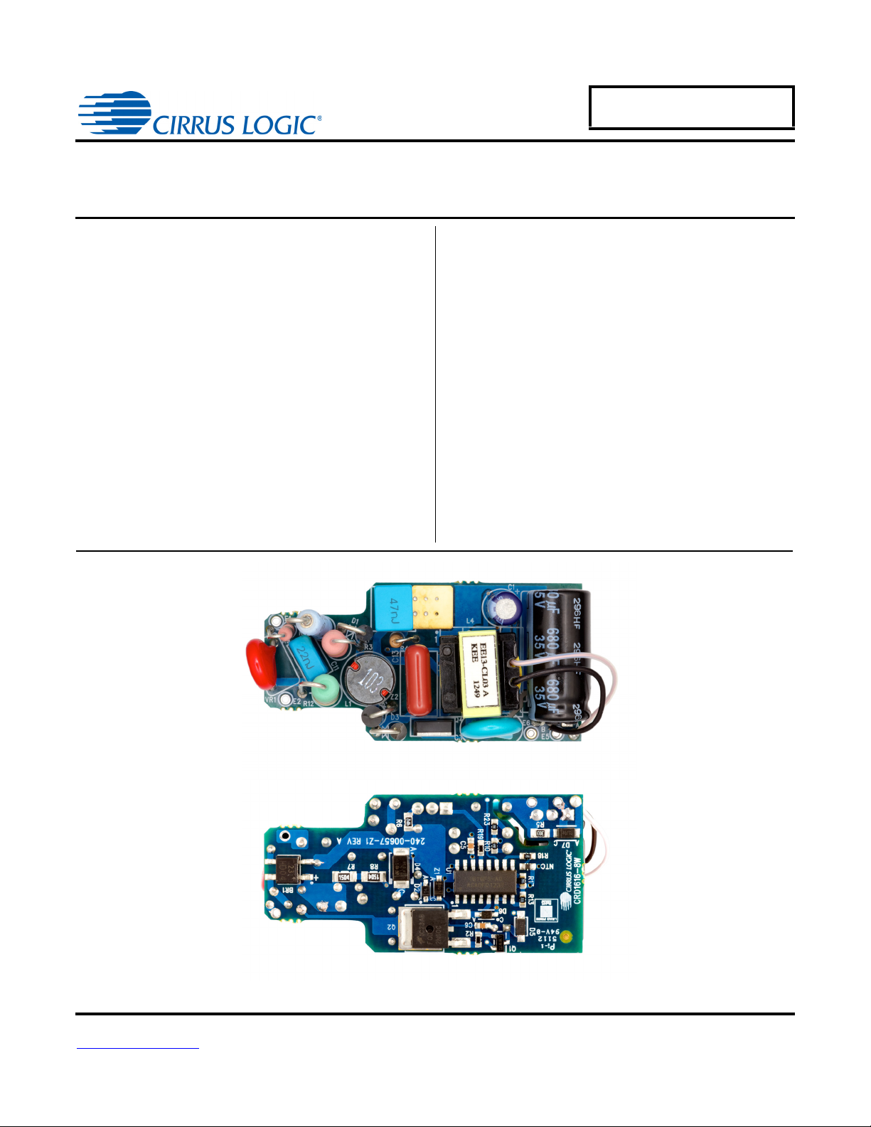
CRD1616-8W
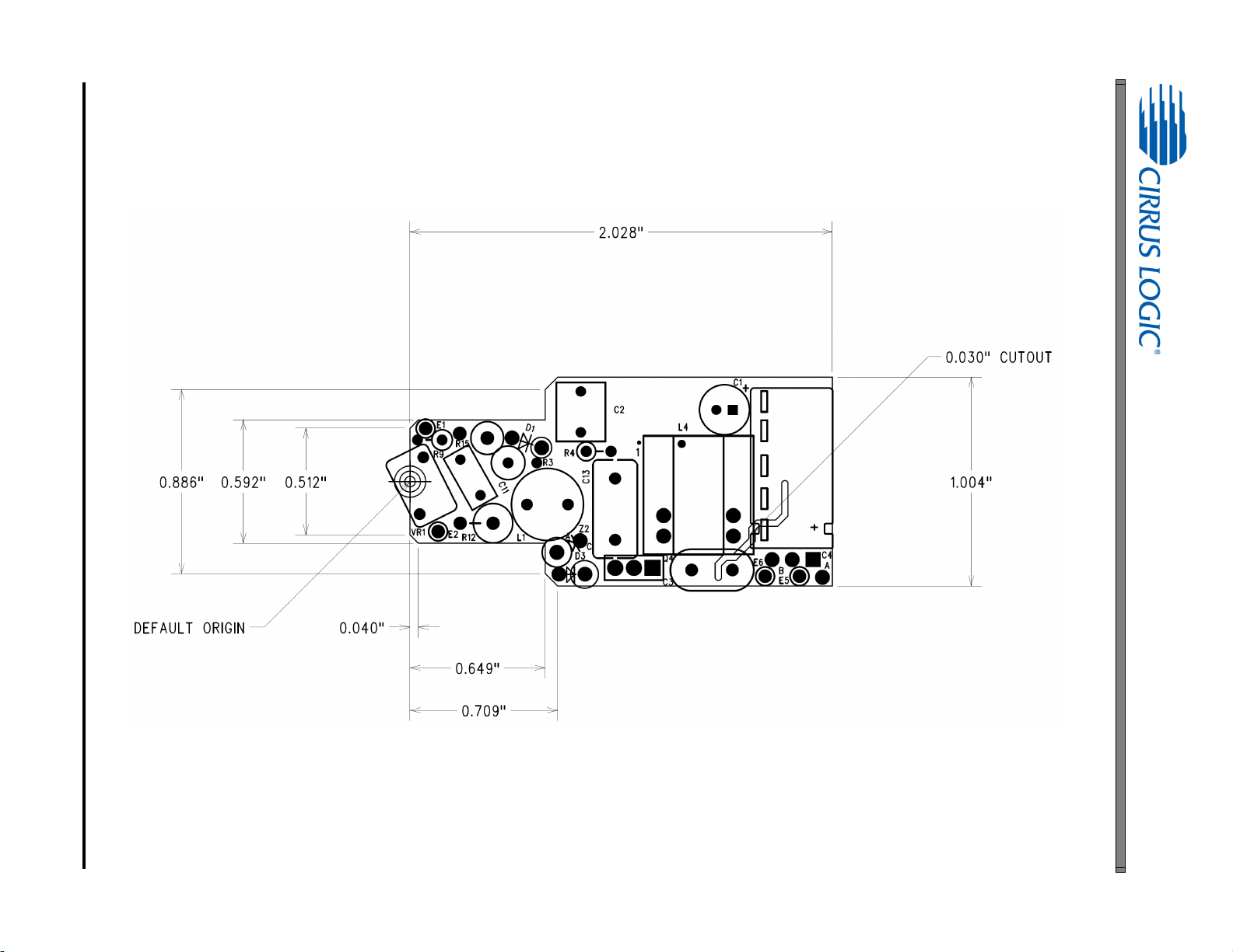
2.028 51.5mm1.004 25.5mm0.65 16.5mm
8 Watt Reference Design
CRD1616-8W
Features
• Quasi-resonant Flyback with Constant-current Output
• Flicker-free Dimming
• Line Voltage 207VAC - 253VAC
• Rated Output Power: 7W
• Efficiency: 82.5% at
• Supports Cirrus Logic CS1616
250mA
for 10LEDs in Series
General Description
The CRD1616-8W reference design demonstrates the
performance of the CS1616 single stage dimmable AC/ DC
LED driver IC with a 250mA output driving
series
. It offers best-in-class dimmer compatibility with
leading-edge, trailing-edge, and digital dimmers. The form
factor is targeted to fit into many LED bulb applications
(GU10, A19, PAR, BR).
DIMENSIONS (OVERALL)
Length Width Height
For more information, see Figure 3 on page 6.
ORDERING INFORMATION
CRD1616-8W-Z 8 Watt Reference Design
Supports CS1616
10LEDs in
Cirrus Logic, Inc.
http://www.cirrus.com
Bottom
Copyright Cirrus Logic, Inc. 2013
(All Rights Reserved)
DEC‘13
DS1003RD4
Page 2
CRD1616-8W
Contacting Cirrus Logic Support
For all product questions and inquiries contact a Cirrus Logic Sales Representative. To find the one nearest to you
go to www.cirrus.com
IMPORTANT NOTICE
Cirrus Logic, Inc. and its subsidiaries ("Cirrus") believe that the information contained in this document is accurate and reliable. However, the information is subject
to change without notice and is provided "AS IS" without warranty of any kind (express or implied). Customers are advised to obtain the latest version of relevant
information to verify, before placing orders, that information being relied on is current and complete. All products are sold subject to the terms and conditions of sale
supplied at the time of order acknowledgment, including those pertaining to warranty, indemnification, and limitation of liability. No responsibility is assumed by Cirrus
for the use of this information, including use of this information as the basis for manufacture or sale of any items, or for infringement of patents or other rights of third
parties. This document is the property of Cirrus and by furnishing this information, Cirrus grants no license, express or implied under any patents, mask work rights,
copyrights, trademarks, trade secrets or other intellectual property rights. Cirrus owns the copyrights associated with the information contained herein and gives
consent for copies to be made of the information only for use within your organization with respect to Cirrus integrated circuits or other products of Cirrus. This consent does not extend to other copying such as copying for general distribution, advertising or promotional purposes, or for creating any work for resale.
CERTAIN APPLICATIONS USING SEMICONDUCTOR PRODUCTS MAY INVOLVE POTENTIAL RISKS OF DEATH, PERSONAL INJURY, OR SEVERE PROPERTY OR ENVIRONMENTAL DAMAGE ("CRITICAL APPLICATIONS"). CIRRUS PRODUCTS ARE NOT DESIGNED, AUTHORIZED OR WARRANTED FOR
USE IN PRODUCTS SURGICALLY IMPLANTED INTO THE BODY, AUTOMOTIVE SAFETY OR SECURITY DEVICES, LIFE SUPPORT PRODUCTS OR OTHER
CRITICAL APPLICATIONS. INCLUSION OF CIRRUS PRODUCTS IN SUCH APPLICATIONS IS UNDERSTOOD TO BE FULLY AT THE CUSTOMER'S RISK
AND CIRRUS DISCLAIMS AND MAKES NO WARRANTY, EXPRESS, STATUTORY OR IMPLIED, INCLUDING THE IMPLIED WARRANTIES OF MERCHANTABILITY AND FITNESS FOR PARTICULAR PURPOSE, WITH REGARD TO ANY CIRRUS PRODUCT THAT IS USED IN SUCH A MANNER. IF THE CUSTOMER
OR CUSTOMER'S CUSTOMER USES OR PERMITS THE USE OF CIRRUS PRODUCTS IN CRITICAL APPLICATIONS, CUSTOMER AGREES, BY SUCH USE,
TO FULLY INDEMNIFY CIRRUS, ITS OFFICERS, DIRECTORS, EMPLOYEES, DISTRIBUTORS AND OTHER AGENTS FROM ANY AND ALL LIABILITY, INCLUDING ATTORNEYS' FEES AND COSTS, THAT MAY RESULT FROM OR ARISE IN CONNECTION WITH THESE USES.
Cirrus Logic, Cirrus, the Cirrus Logic logo designs, EXL Core, and the EXL Core logo design are trademarks of Cirrus Logic, Inc. All other brand and product names
in this document may be trademarks or service marks of their respective owners.
IMPORTANT SAFETY INSTRUCTIONS
Read and follow all safety instructions prior to using this demonstration board.
This Engineering Evaluation Unit or Demonstration Board must only be used for assessing IC performance in a
laboratory setting. This product is not intended for any other use or incorporation into products for sale.
This product must only be used by qualified technicians or professionals who are trained in the safety procedures
associated with the use of demonstration boards.
Risk of Electric Shock
• The direct connection to the AC power line and the open and unprotected boards present a serious risk of electric
shock and can cause serious injury or death. Extreme caution needs to be exercised while handling this board.
• Avoid contact with the exposed conductor or terminals of components on the board. High voltage is present on
exposed conductor and it may be present on terminals of any components directly or indirectly connected to the AC
line.
• Dangerous voltages and/or currents may be internally generated and accessible at various points across the board.
• Charged capacitors store high voltage, even after the circuit has been disconnected from the AC line.
• Make sure that the power source is off before wiring any connection. Make sure that all connectors are well
connected before the power source is on.
• Follow all laboratory safety procedures established by your employer and relevant safety regulations and guidelines,
such as the ones listed under, OSHA General Industry Regulations - Subpart S and NFPA 70E.
Suitable eye protection must be worn when working with or around demonstration boards. Always
comply with your employer’s policies regarding the use of personal protective equipment.
All components and metallic parts may be extremely hot to touch when electrically active.
2 DS1003RD4
Page 3
CRD1616-8W
1. INTRODUCTION
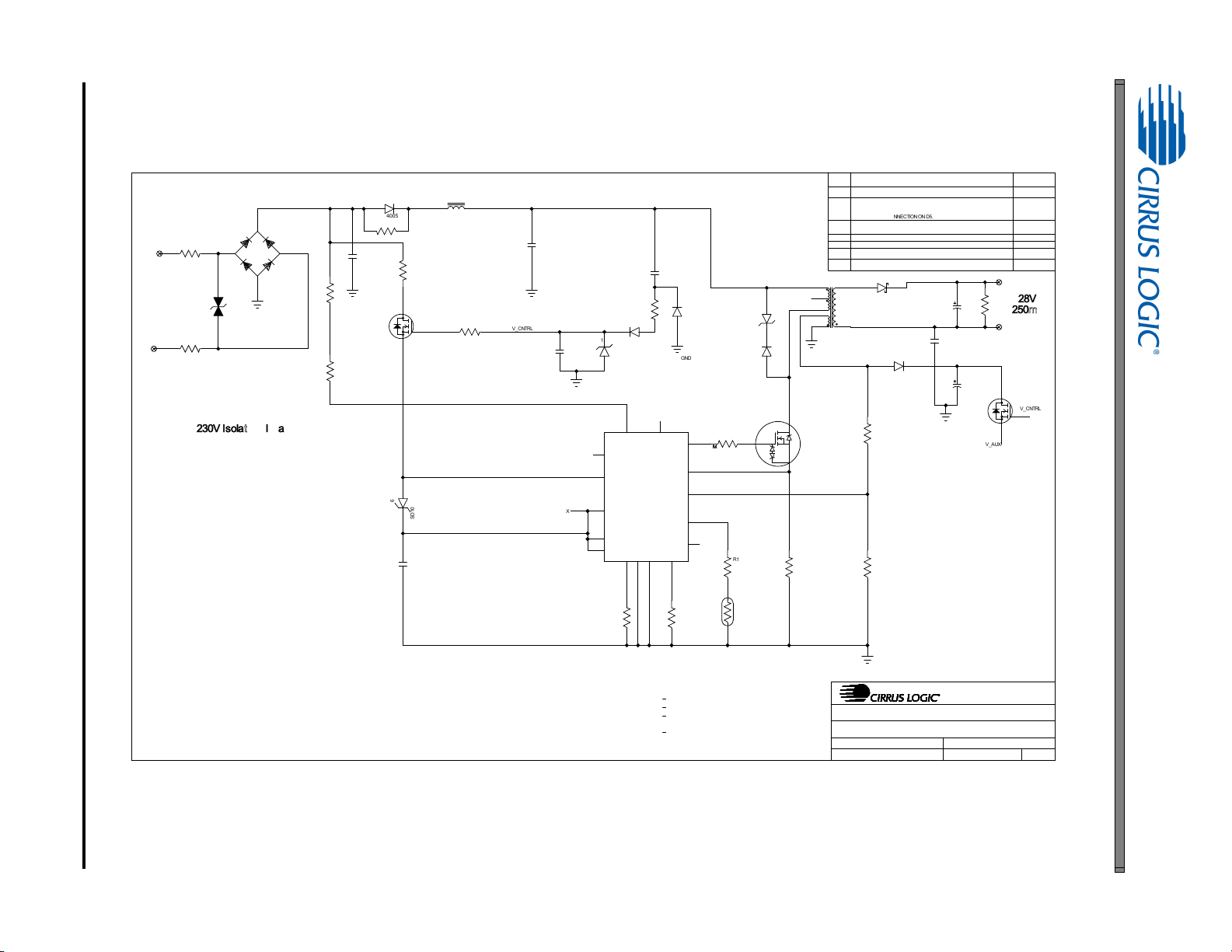
The CS1616 is a 230VAC quasi-resonant flyback mode dimmable LED controller IC. The CS1616 uses a digital control algorithm that is optimized for high efficiency and >0.9 power factor over a wide input voltage range (207VAC
to 253VAC). The CS1616 integrates a dimmer compatibility circuit with a constant output current, quasi-resonant
flyback stage. An adaptive dimmer compatibility algorithm controls the dimmer compatibility operation mode to enable flicker-free operation from 0% to 100% output current with leading-edge, trailing-edge, and digital dimmers.
The CRD1616-8W board is optimized to deliver low system cost in a high-efficiency, flicker-free, phase-dimmable,
solid-state lighting (SSL) solution for incandescent lamp replacement applications. The feedback loop is closed
through an integrated digital control system within the IC. Protection algorithms such as output open/ short,
current-sense resistor open/ short, and overtemperature thermistors protect the system during abnormal conditions.
When using the CS1616 for a design that does not require active clamp circuitry, the CLAMP pin should be left
floating. Details of these features are provided in the CS1616/16 data sheet DS961 Single Stage Dimmable Offline
AC/DC Controller for LED Lamps.
The CRD1616-8W board demonstrates the performance of the CS1616. This reference board has been designed
for an output load of 10
This document provides the schematic for the board. It includes oscilloscope screen shots that indicate various operating waveforms. Graphs are also provided that document the performance of the board in terms of Efficiency vs.
Line Voltage, Output Current vs. Line Voltage, and Output Current vs. Dim Angle for the CS1616 dimmable LED
controller IC.
LEDs in series at 250 mA (28V typical).
Extreme caution needs to be exercised while handling this board. This board is to be used by trained professionals
only.
DS1003RD4 3
Page 4
4 DS1003RD4
600-00657-Z1 REV E
C.LAMBERTC.LAMBERT
SHEET
OFSHEET
ENGINEER
DATE
DRAWN BY
PART #
SHEET
6/4/2013
SCHEM,CRD1616-8W
11
TITLE
SIZE
B
12/17/12A
REV DESCRIPTION DATE
INITIAL RELEASE
127(681/(6627+(5:,6(63(&,),('
$//5(6,67259$/8(6$5(,12+06
$8;,/,$5<+$5':$5($1'5(/$7(''2&80(176
A1
CHGD C11 TO KEMET PHE426KJ5220JR05.
01/23/13
CHGD C13 TO PANASONIC ECQE4683RJF.
CHGD C2 TO KEMET PHE426KJ5470JR05.
CORRECTED CONNECTION ON D5.
ECO1028
ECO1029 B INCORPORATED ECO1028 CHANGES TO THE BOARD LAYOUT.
02/05/13
ECO1050 C
CHANGED D7, FOOT PRINT CHANGED
02/25/13
ECO1070 C1
CHANGED U1 REV FROM B1 TO A0
04/19/13
DECO1080 REMOVED THERMAL PAD FROM U1. 4/25/13
ECO1095 E ADD KEEPOUT ON L4, PIN 8 TO PREVENT SHORT OF REMOVED PIN. 06/04/13
422-00657-01
12
D6
SD103BWS-TP
5
5
15K
-t
17&
100K
5
!"
(
LINE
(
NEUTRAL
R4
1K
PCB DWG-
=
LBL SUBASSY PROD ID AND REV
SCHEMATIC DWG
=
ASSY DWG-
=
'
1N4005
1
2
Z1
NZH16C,115
16V
5
#!#"
Pri
Sec
Aux
4
5
6
7
8
B
A
L4
EE13-CL03
C2
0.047uF
400V
1
3
2
Q2
AOD1N60
G
D
S
Q4
STD3NK80Z-1
5
53.6K
5
4.42 Ohm
&
47uF
ELEC
R15
270
1
2R34.7K
2W
C4
680uF
AL ELEC
R5
30K
(
LINE
(
LINE
1
+
3
2
-
4
%5
HD04-T
C6
1uF
X7R
R10
69.8K
1
G
2
S
3
D
Q1
2N7002P,215
R2 47 OHM
5
1.50M
5
1.50M
1
AUXCNTRL
2
IAC
3
CLAMP
4
SGND
5
SOURCE
6
SDA
7
SCL
8
CTRL1
9
CTRL2
10
EOTP
11
FBSENSE
12
GND
13
GD
14
VDDH
15
NC
16
FBAUX
U1
CS1616-FSZ
1
2
VR1
V275LT4P
275V
12
D7
SS110-TP
100V
C11
0.022uF
MTLPOLY
L1
10mH
C13
0.068uF
MTLPO LY
R9 56 Ohm
R12 100 Ohm
12
D2
1N4148WX-TP
100V
1
2
D4
STTH1L06A
600V
C5
1uF
X7R
1
2
D3
STTH1R06
600V
1
2
Z2
P6KE350A
300V
C3
2200pF
CERAMIC
12
D5
1N4148W-7-F
100V
V_AUX
V_AUX
V_CNTRL
GND
V_CNTRL
2. SCHEMATIC
CRD1616-8W
Figure 1. Schematic
Page 5
3. BILL OF MATERIALS
Item Rev DescripƟon Qty Reference Designator MFG MFG P/N
1 DIODE RECT 400V 0.8A NPB MINIDIP 1 BR1 DIODES INC HD04-T
2 CAP 47uF ±20% 35V AL ELEC NPb RAD 1 C1 KEMET ESK476M035AC3AA
3 CAP 0.047uF ±5%LS 400V MTL NPb RAD 1 C2 KEMET PHE426KJ5470JR05
4 A CAP 2200pF ±10% 2KV CERAMIC NPb TH 1 C3 MURATA DEBB33D222KA2B
5
6 CAP 1uF ±10% 25V X7R CER NPb 0603 2 C5 C6 TDK CGA3E1X7R1E105K
7 CAP 0.022uF ±5%LS 400V MTL NPb RAD 1 C11 KEMET PHE426KJ5220JR05
8 CAP 0.068uF ±5%LS 400V MTL NPb RAD 1 C13 PANASONIC ECQE4683RJF
9 DIODE RECT 600V 1A 50mA NPb DO-41 1 D1 DIODES INC 1N4005
10 DIODE HS SWT 100V 300mA NPb SOD323 1 D2 MICRO COMMERCIAL 1N4148WX-TP
11 DIODE FAST 600V 1A NPb DO-41 1 D3 ST STTH1R06
12 DIODE ULT FAST 600V 1A NPb SMA 1 D4 ST MICROELECTRONICS STTH1L0
6A
13 DIODE FAST SW 100V 400mW NPb SOD123 1 D5 DIODES INC 1N4148W-7-F
14 DIODE SCHOTTKY 350mA 30V NPb SOD323 1 D6 MICRO COMMERCIAL SD103BWS-TP
15 DIODE SKY RECT 100V 1A NPb DO-214AC 1 D7 MCC SS110-TP
16
17 IND 10mH ±10% 34OHM NPb 350DIA TH 1 L1 COILCRAFT RFB0807-103L
18 XFMR 4.0mH ±10% 10KHz NPb TH 1 L4 KUNSHAN EAGERNESS EE13-CL03
19
20 TRAN MSFET nCH 60V 360mA NPb SOT-23 1 Q1 NXP 2N7002P,215
21 TRAN MOSFET nCH 1.3A 600V NPb DPAK 1 Q2 ALPHA & OMEGA AOD1N60
22 TRAN MOSFET nCH 2.5A 800V NPb IPAK 1 Q4 ST MICROELECTRONICS STD3NK80Z-1
23 RES 47 OHM 1/10W ±1% NPb 0603 2 R2 R19 PANASONIC ERJ3EKF47R0V
24 RES 4.7K OHM 2W 5% MTL FILM NPb AXL 1 R3 YAGEO FMP200JR-52-4K7
25 RES 1k OHM 1/2W ±5% CARFL NPb AXL 1 R4 STACKPOLE ELECTRONICS CFM12JT1K00
26 RES 30K OHM 1/8W ±0.1% NPb
0805 1 R5 PANASONIC ERA-6YEB303V
27 RES 4.42 OHM 1/8W ±1% NPb 0805 FLM 1 R6 YAGEO RC0805FR-074R42L
28 RES 1.50M OHM 1/4W ±1% NPb 1206 2 R7 R8 PANASONIC ERJ8ENF1504V
29 RES 56 OHM 1W 5% MTL FILM NPb AXL 1 R9 YAGEO FMP100JR-52-56R
30
31 RES 100 OHM 2W 5% FUSIBLE WW NPb AX 1 R12 YAGEO FKN2WSJR-73-100R
32 RES 51.1k OHM 1/10W±1% NPb 0603 FLM 1 R13 DALE CRCW060351K1FKEA
33 RES 270 OHM 2W ±5% MTL FLM NPb AXL 1 R15 PANASONIC ERG2SJ271
34 RES 53.6k OHM 1/10W±1% NPb0603 FILM 1 R17 DALE CRCW060353K6FKEA
35 RES 15k OHM 1/10W ±1% 0603 FILM 1 R18 DALE CRCW060315K0FKEA
36 RES 3k OHM 1/10W ±5% NPb 0603 FILM 1 R23 DALE CRCW06033K00JNEA
37 A0 IC CRUS TRIAC DIM PFC 230V NPb SO16 1 U
1 CIRRUS LOGIC CS1616-FSZ/A0
38 VARISTOR 275V 80pF 23J 7mm NPb RAD 1 VR1 LITTELFUSE V275LT4P
39 DIODE ZENER 500mW 16V NPb SOD123F 1 Z1 NXP NZH16C,115
40 DIODE TVS 300V 600W NPb DO-204AC 1 Z2 LITTELFUSE P6KE350A
Figure 2. Bill of Materials
CAP 680uF ±20% 35V AL ELEC NPb RAD 1 C4 PANASONIC EEUFR1V681
NO POP PAD H40 P64 NPb TH 4 E1 E2 E5 E6 NO POP NP-PAD-H40P64
CRD1616-8W
DS1003RD4 5
THERM 100K OHM ±5% 0.10mA NPb 0603 1 NTC MURATA NCP18WF104J03RB
RES 69.8k OHM 1/10W ±1% NPb 0603 1 R10 DALE CRCW060369K8FKEA
Page 6
6 DS1003RD4
4. BOARD LAYOUT
Figure 3. PCB Dimensions
CRD1616-8W
Page 7
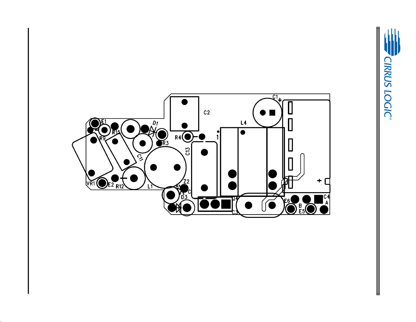
DS1003RD4 7
Figure 4. Top Silkscreen
CRD1616-8W
Page 8
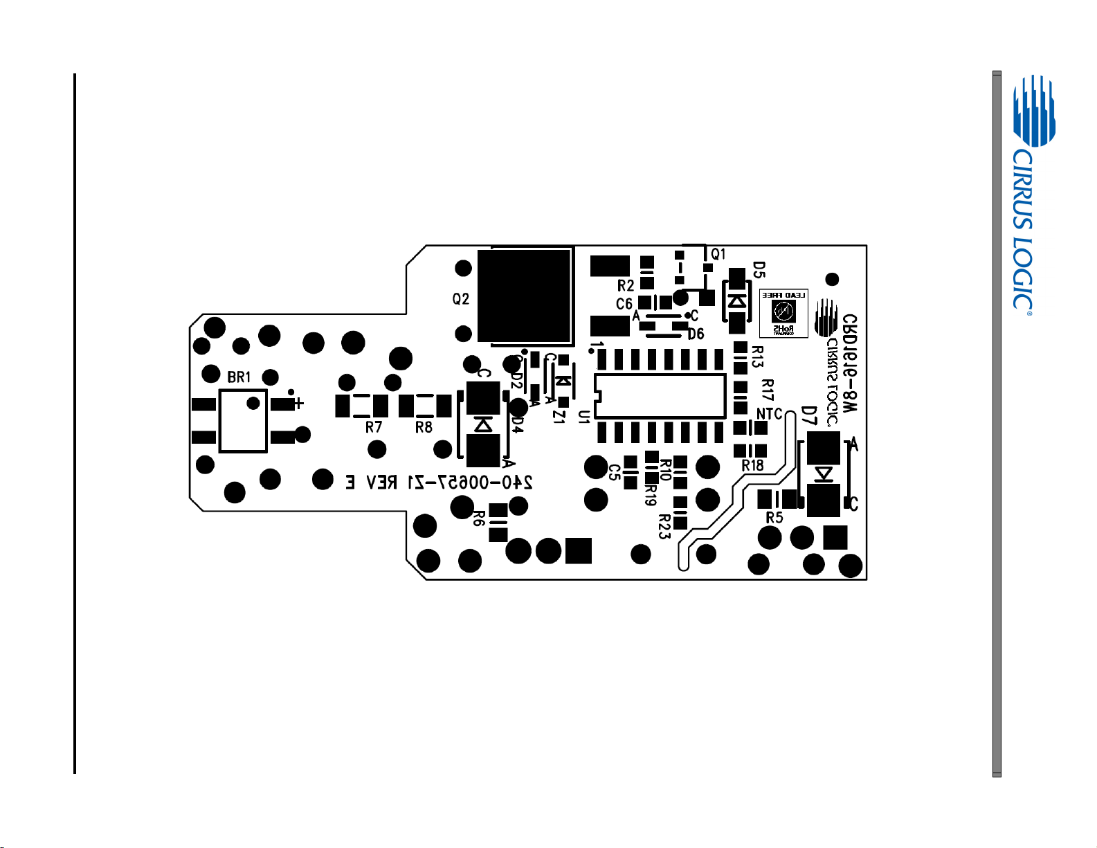
8 DS1003RD4
Figure 5. Bottom Silkscreen
CRD1616-8W
Page 9

DS1003RD4 9
Figure 6. Top Routing
CRD1616-8W
Page 10

10 DS1003RD4
Figure 7. Bottom Routing
CRD1616-8W
Page 11

5. THERMAL IMAGING
Figure 8. Top Thermal
Figure 9. Bottom Thermal
CRD1616-8W
DS1003RD4 11
Page 12
CRD1616-8W
6. DIMMER COMPATIBILITY - A19 WITH CS1616 (230V/ 50HZ)
Input Power 8.34W Dimmer Compatibility 718/ 864 Efficiency 81.7%
Date
1/14/2013 Power Factor
1,5
0.95
Vendor Cirrus Logic EN55015 Compliant (Y/N) Y
Input Voltage
Form Factor
Model #
IC
Topology
Isolation (Y/N)
230V/50Hz Nominal Input Power (W)
A19 Maximum Input Power (W)
CRD1616-8W Output Voltage (V)
CS1616 Output Current (mA)
Flyback
Output Current Ripple
Y Output Power (W)
1,3
1,3
120Hz (mA
1,5
1,5
1,5
p-p
1,4
)
8.34
8.5
27.51
248
200
6.82
Compatibility Spec. 1.0 Efficiency (%) 81.3
Dimmer Type
Flicker Free
Steady-state
# of Lamps # of Lamps # of Lamps # of Lamps
1 5 10 1 5 10 1 5 10 1 5 10
Monotonic
Dimming
Max I
(mA) Min I
OUT
OUT
(mA)
Total
Berker - Leading Edge N Y N Y Y Y - 249 - 8 2 7 12
Bticino - Trailing Edge N Y Y Y Y Y 120 11 3 110 3 3 3 16
Bull - Leading Edge Y N N Y Y Y 251 248 249 3 3 3 14
Busch - Leading Edge Y Y Y Y Y Y 250 249 249 3 3 3 24
Busch - Trailing Edge Y Y Y N Y Y 249 247 248 2 2 2 23
Busch - Trailing Edge Y Y Y N Y Y 249 248 248 2 2 2 23
Chint - Leading Edge N Y Y Y Y N - 245 246 3 3 3 17
Chisen - Leading Edge Y Y Y Y Y Y 249 248 249 3 3 3 24
Chisen - Leading Edge Y Y Y Y Y Y 248 248 248 3 3 3 24
Clipsal - Trailing Edge N Y Y Y Y Y - 249 248 2 2 2 18
Clipsal - Trailing Edge Y Y Y Y Y Y 248 246 248 2 2 2 24
Clipsal - Leading Edge Y Y Y Y Y Y 250 249 249 3 3 3 24
CLSEN - Leading Edge Y Y Y Y Y Y 247 247 250 3 3 3 24
Cshyh - Leading Edge Y Y N Y Y Y 249 247 250 4 3 3 19
Dbang - Leading Edge Y Y Y Y Y Y 248 246 249 3 3 3 24
Elro - Twilight Sensor Y Y Y Y Y Y 243 245 246 0 0 0 24
Elro - Motion Detector Y Y Y Y Y Y 243 245 246 0 0 0 24
Futina - Leading Edge Y Y Y Y Y Y 244 248 247 3 3 3 24
Gira - Leading Edge N N N Y Y Y 249 250 248 3 3 3 9
HPM - Trailing Edge Y Y Y N Y N 220 216 211 2 2 2 19
Jung - Leading Edge Y N Y Y Y Y 249 249 249 2 10 2 19
Legrand - Trailing Edge Y Y Y Y Y Y 75 73 73 2 2 2 21
Leiben - Leading Edge Y Y Y Y Y Y 249 247 248 3 3 3 24
12 DS1003RD4
Page 13
CRD1616-8W
Dimmer Type
Flicker Free
Steady-state
# of Lamps # of Lamps # of Lamps # of Lamps
1 5 10 1 5 10 1 5 10 1 5 10
Monotonic
Dimming
Max I
(mA) Min I
OUT
OUT
(mA)
Total
Lonon - Leading Edge Y Y Y Y Y Y 248 248 251 3 3 3 24
Lutron - Leading Edge Y N N Y Y Y 249 248 249 3 3 3 14
Lutron - Leading Edge Y Y N Y Y Y 244 245 246 3 3 3 19
MK - Leading Edge Y N N Y Y Y 250 251 250 3 3 3 14
N&L - Trailing Edge N Y Y N N N 213 209 202 2 3 2 13
Opus - Leading Edge Y Y N Y Y Y 249 248 249 3 3 3 19
Siemens - Leading Edge Y Y N Y Y Y 247 247 249 3 3 2 19
Songri - Leading Edge Y Y Y Y Y Y 248 248 249 3 3 3 24
T&J - Leading Edge Y Y N Y Y Y 248 248 249 3 3 3 19
T&J - Leading Edge Y Y Y Y Y Y 250 248 250 3 3 3 24
TCL - Leading Edge N Y N Y N Y - 243 246 3 3 3 12
TNC - Leading Edge Y Y N Y Y Y 247 247 248 3 3 3 19
Wuyun - Trailing Edge Y Y Y Y Y Y 249 250 247 3 2 2 24
Overall Total 718
Notes: 1. Tested at nominal input voltage, nominal input frequency, and without a dimmer, after soaking for 15 minutes
2. Compliant with IEC 61000-3-2 Class C < 25 W
3. Average
4. Peak-to-peak
5. Measured with Chroma 66202 Power Analyzer
DS1003RD4 13
Page 14

CRD1616-8W
99.5T
#37AWG
(0.12mm)
140.5 T
#37 AWG
(0.12 mm)
25T
#31AWG
(0.226mm)
Primary
4
8
5
6
Auxili ary
7
Secondary
32T
#30AWG
(0.25mm)
A
B
Figure 10. Flyback Transformer Schematic
7. INDUCTOR CONSTRUCTION
The CRD1616-8W provides power factor correction and dimmer compatibility with a constant output current, quasiresonant flyback stage. The following sections describe the flyback transformer installed on the CRD1616-8W.
7.1 Flyback Transformer
The flyback transformer stage is a quasi-resonant peak current-regulated DC-DC converter capable of delivering
the highest possible efficiency with constant current output while minimizing line frequency ripple. The auxiliary winding is used for zero-current detection and overvoltage protection.
7.1.1 Electrical Specifications
Characteristics conditions:
• Operating temperature range: -25 °C to +120 °C (including coil heat)
Parameter Condition Sym Min Typ Max Unit
Flyback Transformer
f
Electrical Strength (Note 1)
Primary Inductance (Note 2)
Primary Leakage Inductance (Note 2)
f
resonant
f
resonant
Primary DC Resistance (Note 2)
Secondary DC Resistance (Note 3)
Auxiliary DC Resistance (Note 4)
Notes: 1. Time = 2sec.
2. Measured across pins 4 and 5.
3. Measured across pins B and A.
4. Measured across pins 6 and 7.
14 DS1003RD4
=50/60Hz
operate
=10kHz, 0.3V at
=10kHz, 0.3V at
t
=20°C
DCR
t
=20°C
DCR
t
=20°C
DCR
20°C
20°C
L
P
L
K
- 1200 - V
3.6 4.0 4.4 mH
--80H
8.8 11 13.2
- - 0.372
0.304 0.38 0.456
RMS
Page 15
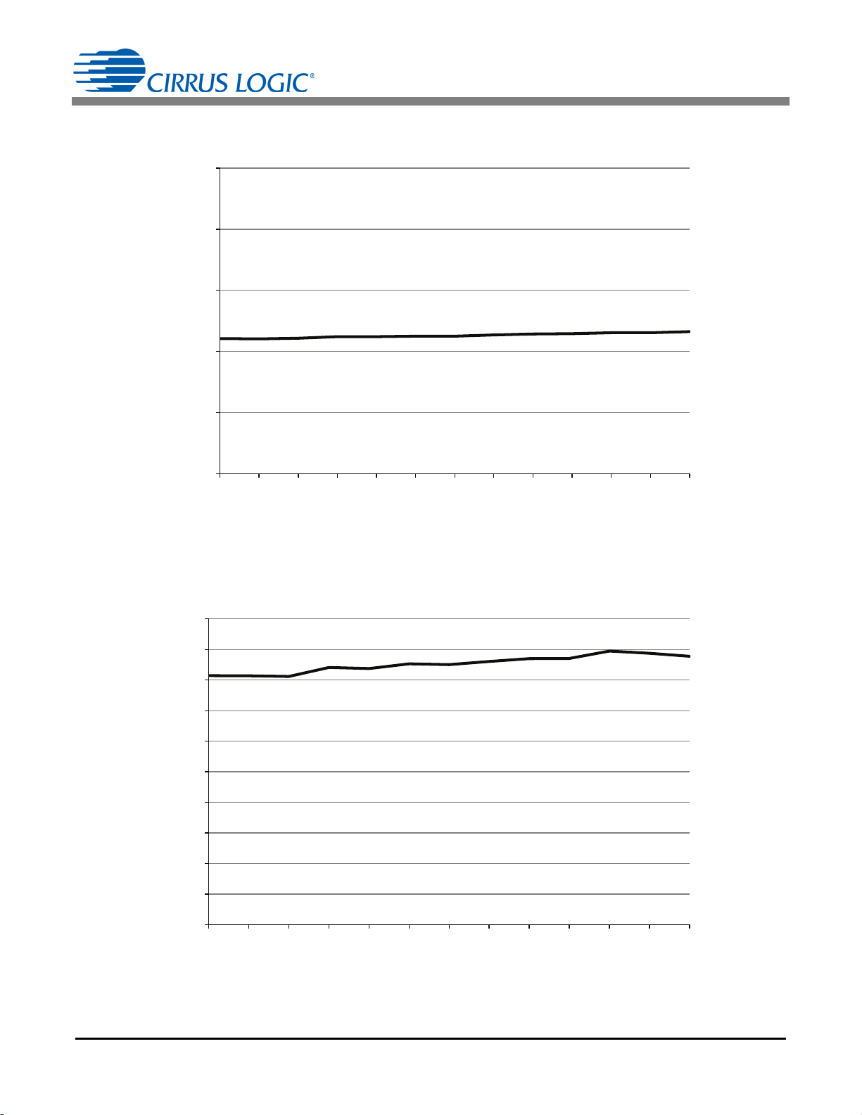
8. PERFORMANCE PLOTS
0.2
0.22
0.24
0.26
0.28
0.3
207 211 215 219 223 227 230 233 237 241 245 249 253
Output Current (A)
Line Voltage (V)
Figure 11. Output Current vs Line Voltage
Figure 12. Typical Efficiency vs Line Voltage
75
76
77
78
79
80
81
82
83
84
85
207 211 215 219 223 227 230 233 237 241 245 249 253
Efficiency (%)
Line Voltage (V)
CRD1616-8W
DS1003RD4 15
Page 16

CRD1616-8W
Figure 13. Power Factor vs Line Voltage
0.90
0.91
0.92
0.93
0.94
0.95
0.96
0.97
0.98
0.99
1.00
207 211 215 219 223 227 230 233 237 241 245 249 253
Power Factor
Line Voltage (V)
10
11
12
13
14
15
16
17
18
19
20
207 211 215 219 223 227 230 233 237 241 245 249 253
THD (%)
Line Voltage (V)
Figure 14. THD vs Line Voltage
16 DS1003RD4
Page 17

CRD1616-8W
0
0.05
0.1
0.15
0.2
0.25
0.3
30 40 50 60 70 80 90 100 110 120 130 140 150 160 170 180
Output Current (A)
Dim Angle (°)
Leading Edge
Trailing Edge
Figure 15. Typical Output Current vs Dim Angle
DS1003RD4 17
Page 18

CRD1616-8W
Figure 16. No-dimmer Mode, Startup, 230 VAC
Figure 17. No-dimmer Mode, Steady-state, 230VAC
18 DS1003RD4
Page 19

CRD1616-8W
Figure 18. Flyback FET Q3, 230VAC
Figure 19. Flyback FET Q3, 230VAC (with Zoom In)
DS1003RD4 19
Page 20

CRD1616-8W
Figure 20. Flyback FET Q3, 230VAC (with Zoom In)
Figure 21. Leading-edge Dimmer Mode, Steady-state, 230VAC
20 DS1003RD4
Page 21

CRD1616-8W
Figure 22. Trailing-edge Dimmer Mode, Steady-state, 230VAC
DS1003RD4 21
Page 22

9. CONDUCTED EMI
Figure 23. Conducted EMI
Device Under Test: CRD1616-8W-Z Operating Conditions: NOMINAL
Test Specification: EN55022:2010 Operator Name: CAL
Scan Settings (1 Range)
Frequencies Receiver Settings
Start Stop Step Res BW M-Time Atten Preamp
150kHz 30MHz 4.5kHz 9kHz (6dB) 50ms Auto Off
Final Measurement
Detectors: QP, AV Peaks: 25 Meas Time: See scan settings Acc. Margin: 12dB
CRD1616-8W
Final Measurement Results
Trace
1 QP 0.15 58.20 66.00 -7.80 N / on
2 AV 0.1815 42.87 54.42 -11.55 N / on
1 QP 2.5125 52.99 56.00 -3.01 N / on
2 AV 10.0005 40.93 50.00 -9.07 N / on
* = Limit Exceeded
22 DS1003RD4
Frequency
(MHz)
Level
(dB
V)
Limit
(dBV)
Delta Limit
(dB)
Delta Ref
(dB)
Comment
Page 23

10.REVISION HISTORY
Revision Date Changes
RD1 FEB 2013 Final release
RD2 APR 2013 Context clarification
RD3 JUL 2013 Content updated using PCBA Rev C
RD4 DEC 2013 Corrected typographical errors
CRD1616-8W
DS1003RD4 23
 Loading...