

Page 1
TM
CobraNet
Routing Primer
Steve Gray, Cirrus Logic, Inc.
Configuring CobraNetTM systems to properly route audio is fairly straightforward once the underlying
concepts are understood. This document explains the concepts behind end to end routing and how to
configure CobraNet
CobraNet
TM
device Data Sheets and Reference Manuals.
The variables referred to in this document are described in the CobraNet
TM
interfaces to route audio channels. Use this document as a companion to the available
TM
Programmer’s Reference. They
are known as Management Interface (MI) variables and can be read and written via the hardware Host
Management Interface (HMI) or via SNMP over the network.
The signals referred to are described in the Datasheet or Hardware Reference Manual applicable to the
particular CobraNet
TM
interface in use.
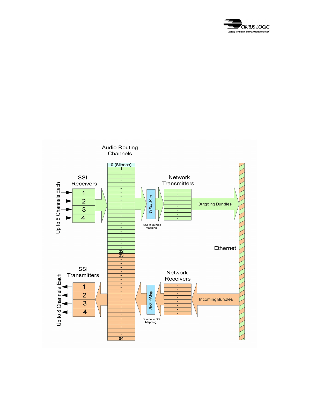
Referring to Figure 1 below, let’s consider the components of CobraNetTM audio routing.
Fig. 1 Simplified Routing Schematic
CobraNetTM Audio Routing Primer Rev. 1.2 ©Copyright 2004 Cirrus Logic, Inc
Page 1 of 9
Page 2

Components of Routing
Bundles
A Bundle is the basic unit of data for transporting audio over a CobraNetTM network and can contain from
zero to eight audio sub-channels. Sample size, sample rate and transmission latency all have an impact on
processor bandwidth and packet sizes required to process and transmit the audio data. These factors can limit
the number of audio channels that can be processed by a CobraNetTM interface. The maximum number of
audio sub-channels allowable per bundle will be from 3 to 8 depending on these settings. The maximum
number of bundles possible can also be affected by these settings. Maximum sub-channel count per bundle
will typically be eight but may be less depending on the particular configuration.
An important attribute of the Bundle is the identifying number assigned to it (the Bundle number). The
Bundle number determines both where the data is sent and, to a large extent, how it is sent. When a receiver
on one interface is assigned the same bundle number as that of a transmitter on another interface, the
CobraNet
interfaces.
Bundles can be transmitted using the following modes:
Refer to the Programmer’s reference for information on valid bundle numbers and how they affect addressing
modes.
TM
protocol will automatically establish a connection and begin transmitting audio data between the
• Unicast (one-to-one)
• Multiple unicast (up to four copies unicast to more than one receiver)
• Multicast (one bundle to an unlimited number of receivers)
• Private (same as unicast or multicast but requiring specification of a MAC address)
Network Transmitters and Receivers
Transmitters and Receivers are logical entities within the CobraNetTM interface which are closely coupled to
the concept of Bundles. Each transmitter or receiver is capable of sending or receiving one Bundle. The
number of transmitters and receivers within a CobraNetTM interface is dependant on the particular
implementation and is fixed by the firmware. The user can configure the number of available transmitters or
receivers to be used.
Synchronous Serial Interface
Each CobraNetTM interface contains one or more Synchronous Serial Interfaces, or SSI’s. SSI’s carry
multiplexed audio data into and out of the CobraNet
DACs, ADCs, DSP processors and other digital audio interfaces. See Appendix C for more information on
the SSI.
TM
interface in time slices and are typically connected to
Audio Routing Channels
Audio routing channels are used to map audio data between a multiplexed SSI time slice and a bundle subchannel. CobraNet
>32 are used for transmitting and channels 33->64 are used for receiving. The actual number of routing
channels available is dependant on the particular CobraNet
special case which is, strictly speaking, not a routing channel. Channel 0, when assigned to a transmitter
Bundle, will cause transmission of an empty channel equivalent to silence. Channel 0, when assigned to a
receiver bundle sub-channel, will cause the bundle sub-channel received to be discarded.
For practical purposes, each unique audio routing channel can be thought of as having a fixed association
with a unique SSI time slice. In reality, audio routing channels are assigned to SSI time slices via the
audioMap variable array. Omission of this variable in Figure 1 is intentional. It should not be changed. See
Appendix B for default SSI to Audio Routing channel assignments.
TM
interfaces contain up to 64 audio routing channels numbered from 1 to 64. Channels 1-
TM
implementation. Channel 0 is an additional
CobraNetTM Audio Routing Primer Rev. 1.2 ©Copyright 2004 Cirrus Logic, Inc
Page 2 of 9
Page 3

Bundle to Audio Routing Channel Mapping – txSubMap and rxSubMap
The RxSubMap and TxSubMap variable arrays are used to map Audio Routing Channels to and from Bundle
sub-channels. As described above, an Audio Routing Channel can be thought of as assigned to a specific time
slice within a Synchronous Serial Interface. Therefore, assigning an Audio Routing Channel to a bundle subchannel is equivalent to assigning an SSI time slice to a bundle sub-channel. See Appendix B for default SSI
to Audio Routing channel assignments.
Routing Variables
• txBundle *1 - Each transmitter has a txBundle variable associated with it which specifies the Bundle
Number assigned to that transmitter. There is one instance of this variable for each transmitter.
• rxBundle
Number assigned to that receiver. There is one instance of this variable for each receiver.
• txSubMap *
• rxSubMap *
• txSubFormat *
• rxSubFormat *
• Each interface has one modeRateControl variable which specifies the latency and sample rate used
for all bundles transmitted and received by the interface.
*1
Array variables. There is one instance of this variable for each transmitter and each receiver.
*2
Array variables that are also members of an array. There are multiple instances of this variable for
each transmitter and each receiver.
*3
8 equals the maximum permissible number of audio sub-channels per bundle.
*1
- Each receiver has an rxBundle variable associated with it which specifies the Bundle
2
- Each transmitter has up to 8 txSubMap variables associated with it. *3
2
- Each receiver has up to 8 rxSubMap variables associated with it. *3
2 -
Each transmitter has up to 8 txSubFormat variables associated with it. *3
2
- Each receiver has up to 8 rxSubFormat variables associated with it. *3
Putting it Together
To route audio between two CobraNetTM interfaces, both the transmitter and receiver must be configured to
send and receive audio channels. In many cases default values can be used and only txSubMap, rxSubMap,
txBundle and rxBundle variables need be set.
Transmitter Configuration
• Assign a bundle number to the transmitter using txBundle.
• Assign Audio Routing channels (and by extension SSI audio channels) to the transmitter (Bundle)
using txSubMap.
• Specify the format of the channels using txSubFormat
• Make sure the value of modeRateControl agrees with the selected txSubFormat.
• Make sure txSubCount for each transmitter is greater than or equal to the number of channels being
transmitted in the bundle. If the value of txSubCount is larger than required, unassigned subchannels will be sent as empty channels.
Receiver Configuration
• Assign a bundle number to a receiver using rxBundle.
• Assign Audio Routing channels (and by extension SSI audio channels) to the receiver (Bundle)
using rxSubMap
• Make sure the value of modeRateControl agrees with the format of the channels to be received.
CobraNetTM Audio Routing Primer Rev. 1.2 ©Copyright 2004 Cirrus Logic, Inc
Page 3 of 9
Page 4

Example:
We have two standard CM-2 modules to be configured as a transmitter and a receiver. We want to send
the audio data with standard latency, a 48-kHz sample rate and 20 bit sample size.
We would like to send two audio channels from the transmitter to the receiver in one unicast bundle.
Bundle number 273 is a valid unicast bundle number suitable for use.
SSI interface 1 is connected to a 2 channel A to D on the transmitter and SSI interface 1 is connected to a
2 channel D to A on the receiver.
For the transmitting interface the following values should be set:
txBundle 273 Assign bundle number to transmitter
txSubCount >= 2 Make sure bundle is big enough
txSubMap.1 1 Assign audio routing channel to 1
txSubMap.2 2 Assign audio routing channel to 2
txSubFormat.1 0x54000 Set format of 1st audio channel
txSubFormat.2 0x54000 Set format of 2nd audio channel
modeRateControl 0x600 Set interface latency and sample rate
For the receiving interface the following values should be set:
rxBundle 273 Assign bundle number to receiver
rxSubMap.1 33 Assign 1
st
bundle channel to audio routing channel
rxSubMap.2 34 Assign 2nd bundle channel to audio routing channel
modeRateControl 0x600 Set interface latency and sample rate
Once the variables are properly set, the CobraNetTM protocol takes over to make sure the Bundles (audio
data) go to and from the correct interfaces. The reservation and reverse reservation components of the
CobraNetTM protocol, which are transparent to the user, automatically detect when a transmitter and one or
more receivers on the network have the same bundle numbers assigned. It will then establish the connection
between these interfaces via the permissions component of the protocol, again transparent to the user, and
cause bundles to flow from the transmitting interface to one or more receiving interfaces with the same
bundle number assignment(s).
Refer to the Programmer’s Reference for detailed information about addressing these variables via HMI or
SNMP.
st
bundle channel
nd
bundle channel
Additional Information
Refer to the Cirrus Logic Application Note “Bundle Assignments In CobraNetTM Systems” for further
information on the use of bundles and their implications on network design and utilization.
CobraNetTM Audio Routing Primer Rev. 1.2 ©Copyright 2004 Cirrus Logic, Inc
Page 4 of 9
Page 5

Appendix A - MI Variables used in routing
Refer to the CobraNet
txBundle
rxBundle:
Array variables which set the bundle number that a transmitter or receiver will use. There is one
instance of these variables for each Receiver or Transmitter.
Defaults: All variables = 0 for standard CobraNet
May be initialized to other values depending on product.
txSubMap:
An array variable which maps which Audio Routing Channel goes to which bundle sub-channel.
There are multiple instances of this variable for each transmitter.
Defaults: Transmitter 1 = 1 -> 8
Transmitter 2 = 9 -> 16
Transmitter 3 = 17 -> 24
Transmitter 4 = 25 -> 32
rxSubMap:
An array variable which maps which bundle sub-channel goes to which Audio Routing Channel.
There are multiple instances of this variable for each receiver.
Defaults: Receiver 1 = 32 -> 40
Receiver 2 = 41 -> 48
Receiver 3 = 49 -> 56
Receiver 4 = 57 -> 64
txSubFormat:
An array variable which sets the audio format of each bundle sub-channel. There are multiple
instances of this variable for each transmitter.
Default: 0x54000 = 5-1/3 mS latency, 48KHz sample rate, 20 bit sample size
rxSubFormat
As above for txSubFormat except for the following:
• rxSubFormat is Read only
• The LSB will be set to 1 when the audio channel is being properly decoded. If LSB is seen
Default: N.A.; Set based on format of received sub-channel
txSubCount:
An array variable which sets the number of sub-channels contained in a bundle. Fewer than the
maximum number of channels allowable can be specified. This value must be greater than or equal
to the number of channels to be sent in a bundle. There is one instance of this variable per
Transmitter.
Default: 8
TM
Programmer’s Reference for more detailed information on these variables.
set to 0, then the interface recognizes the format but cannot decode it (probably due to an
incompatible modeRateControl value).
TM
interfaces.
CobraNetTM Audio Routing Primer Rev. 1.2 ©Copyright 2004 Cirrus Logic, Inc
Page 5 of 9
Page 6

modeRateControl:
Must be set the same on both the sending and receiving interfaces. There is one modeRateControl
variable per CobraNet
particular CobraNet
TM
interface and its value affects all audio channels. All channels on a
TM
node must be set to the same latency (1 1/3, 2/23 or 5 1/3) and sample rate
(48-kHz or 96-kHz). Sample sizes (16, 20 or 24 bits), as specified by txSubFormat, can vary by
channel, and are not affected by modeRateControl. The sample rate and latency component of
txSubFormat must set in agreement with the value of modeRateControl.
Default: 0x600 - 5 1/3 mS latency, 48kHz
CobraNetTM Audio Routing Primer Rev. 1.2 ©Copyright 2004 Cirrus Logic, Inc
Page 6 of 9
Page 7

Appendix B – SSI Interface Theory
There are typically four Synchronous Serial Interfaces in a CobraNetTM interface. This number can differ
depending on product and/or configuration. SSI interfaces are configured at the factory to carry two to eight
audio channels each, in each direction. The number of audio channels multiplexed on an SSI will be reflected
in the rate of the audio bit clock (SCLK). The word clock (FS1) will run at the configured sample rate of 48kHz or 96-kHz. Each doubling of audio channels on the SSI will result in a doubling of the SCLK rate. For 2
channels per SSI, the SSI interface can be connected directly to D to A and A to D converters in most cases.
For higher channel counts the SSI data and/or SLCK must be multiplexed or de-multiplexed in order to
interface to the converters. The SSI interface always assumes use of a 32 bit sample size; in actual use the
relevant data within each sample will be 16, 20 or 24 bits.
The SSI carries multiplexed audio data in one of three modes. The mode is fixed in firmware at the factory
and is described in detail in the Hardware Reference Manual or Data Sheet applicable to the particular
CobraNetTM interface in use.
Example:
A CM-2 module (based on the CS18101) chip is typically configured to handle 8 audio input channels and 8
audio output channels. There are four SSI interfaces, each of which is capable of carrying 2 audio channels in
each direction.
Therefore, the interface’s word clock (FS1 signal) will be running at the configured sample rate of 48-kHz or
96-kHz and the bit clock (SCLK) will be running at 64 times FS1 (or at FS64). This SCLK rate allows
multiplexing of two audio channels of up to 32 bits each on each SSI channel in each direction; or one
channel per half cycle of FS1. SSI channels 1, 2, 3 and 4 will each contain audio channels 1 and 2 for each
direction. i.e. 4 SSI channels x 2 audio channels per SSI x 2 directions = 8 channels in and 8 channels out, or
8 x 8. Refer to the Hardware Reference Manual or Data Sheet applicable to the particular CobraNet
interface in use for more detail.
TM
CobraNetTM Audio Routing Primer Rev. 1.2 ©Copyright 2004 Cirrus Logic, Inc
Page 7 of 9
Page 8

Appendix C – Default SSI to Audio Routing Channel Mapping
2 x 2 Interface
SSI Interface SSI Timeslice
1
1 33 1
2 34 2
Audio Routing
Channel (Receive)
8 x 8 Interface
SSI Interface SSI Timeslice
1
2
3
4
1 33 1
2 34 2
1 35 3
2 36 4
1 37 5
2 38 6
1 39 7
2 40 8
Audio Routing
Channel (Receive)
16 x 16 Interface
SSI Interface SSI Timeslice
1
2
3
4
1 33 1
2 34 2
3 35 3
4 36 4
1 37 5
2 38 6
3 39 7
4 40 8
1 41 9
2 42 10
3 43 11
4 44 12
1 45 13
2 46 14
3 47 15
4 48 16
Audio Routing
Channel (Receive)
Audio Routing
Channel (Transmit)
Audio Routing
Channel (Transmit)
Audio Routing
Channel (Transmit)
CobraNetTM Audio Routing Primer Rev. 1.2 ©Copyright 2004 Cirrus Logic, Inc
Page 8 of 9
Page 9

Appendix B – continued
32 x 32 Interface
SSI Interface SSI Timeslice
1
2
3
4
Audio Routing
Channel (Receive)
1 33 1
2 34 2
3 35 3
4 36 4
5 37 5
6 38 6
7 39 7
8 40 8
1 41 9
2 42 10
3 43 11
4 44 12
5 45 13
6 46 14
7 47 15
8 48 16
1 49 17
2 50 18
3 51 19
4 52 20
5 53 21
6 54 22
7 55 23
8 56 24
1 57 25
2 58 26
3 59 27
4 60 28
5 61 29
6 62 30
7 63 31
8 64 32
Audio Routing
Channel (Transmit)
CobraNetTM Audio Routing Primer Rev. 1.2 ©Copyright 2004 Cirrus Logic, Inc
Page 9 of 9
 Loading...