

Page 1
Evaluation Board for the CS6422
CDB6422
Features
z Includes analog, digital (µ-law/a-law), and
POTS (Plain Old Telephone Service)
network interfaces
z Variable gain (±20 dB) and user-defined
fixed-gain options for analog acoustic and
network inputs and outputs
z Integrated DTMF generator and keypad
provide dialing function
z Operates from +5 V or +12 V power supply,
allowing for use in car
z Operates in stand-alone or PC-based
configuration
z On-board EEPROM stores CS6422
configuration settings
z On-board speaker driver capable of driving
1 Watt into a 4 Ω load with less than 1% THD
AIN-MIC
AIN-RCA
AOUT-RCA
ACOUSTIC
INPUT/
OUTPUT
GAIN AND
FILTERING
CS6422
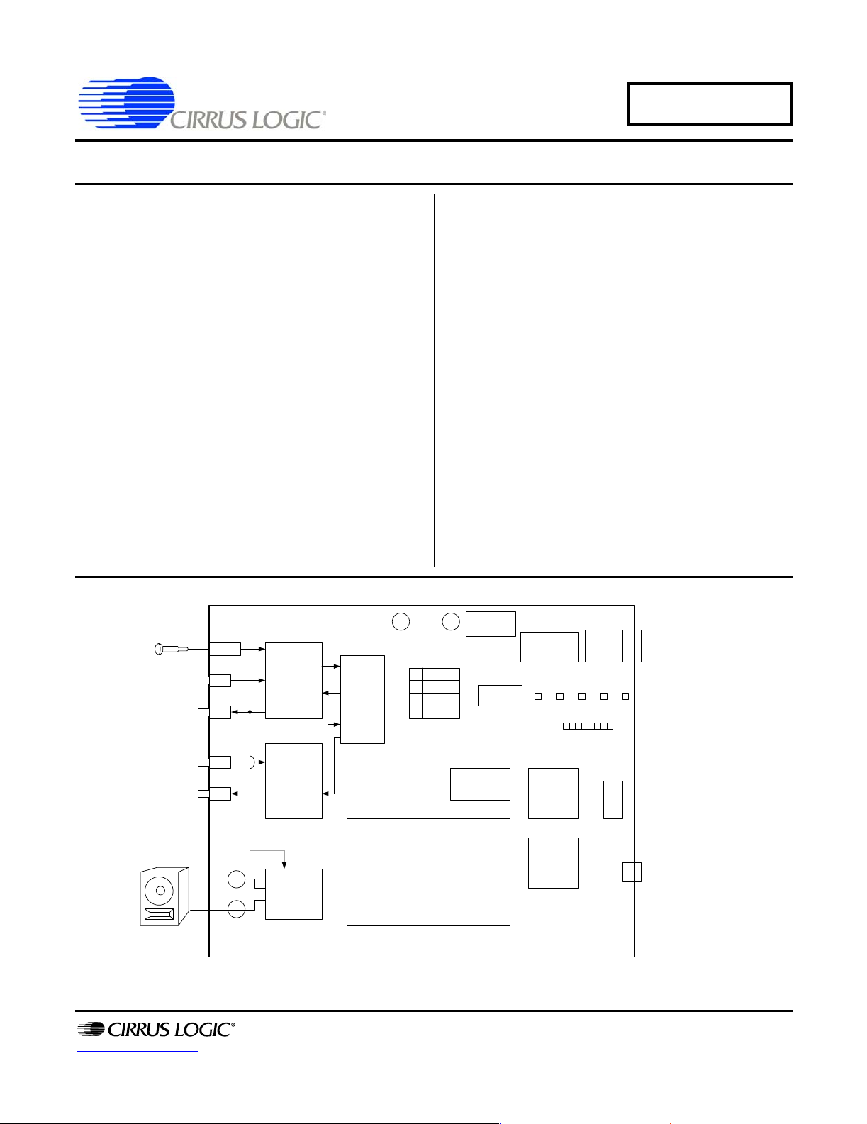
Description
The CDB6422 provides an easy platform to evaluate the
performance of the CS6422 echo cancelling IC in a target system. To facilitate evaluation, the board provides
a wide selection of network interfacing options (analog
telephone line, µ-law/a-law PCM data, or analog RCA
jack). The analog interfaces support both fixed and va riable gain options to allow for level-matching with target
hardware. The board includes a keypad and a DTMF
generator to enable dialing on standard analog telephone systems.
The board can operate from a single +12V power supply
and can be used in a stand-alone configuration allowing
for easy testing in car cellular hands-free applications.
ORDERING INFO
CDB6422 Evaluation Board
+5V/+12VGND
VOLTAGE
KEYPAD
REGULATOR
DIP
SWITCH
MICRO-
CONTROLLER
µC
6422
RESET
RST
LOAD
RS232
VOLDNVOL
RS-232
SERIAL
PORT
UP
http://www.cirrus.com
NIN-RCA
NOUT-RCA
SPKR+
SPKR-
NETWORK
INPUT/
OUTPUT
GAIN AND
FILTERING
1 WATT
SPEAKER
DRIVER
DTMF
TRANSCEIVER
PATCH AREA
Copyright © Cirrus Logic, Inc. 2006
(All Rights Reserved)
µ-LAW
CODEC
DAA
LEDs
DIGITAL
PCM
HEADER
ANALOG
PHONE
LINE
MAR ‘06
DS295DB2
Page 2

CDB6422
TABLE OF CONTENTS
1. GENERAL DESCRIPTION ...............................................................................................................4
2. HARDWARE .....................................................................................................................................4
2.1 Powering the Board ...................................................................................................................4
2.2 Analog Configuration .................................................................................................................4
2.2.1 Acoustic Input ...............................................................................................................4
2.2.1.1 AIN1: ............................................................................................................4
2.2.1.2 MIC_BIAS: ...................................................................................................4
2.2.1.3 AIN2: ............................................................................................................4
2.2.1.4 AIN3, AIN4: ..................................................................................................4
2.2.1.5 AIN5: ............................................................................................................5
2.2.1.6 AIN6, AIN7: ..................................................................................................5
2.2.2 Acoustic Output ............................................................................................................5
2.2.2.1 AOUT1: ........................................................................................................5
2.2.2.2 AOUT2: ........................................................................................................5
2.2.2.3 AOUT3, AOUT4: .......................................................................................... 5
2.2.2.4 AOUT5: ........................................................................................................5
2.2.2.5 AOUT6: ........................................................................................................5
2.2.2.6 SPEAKER_GAIN: ........................................................................................5
2.2.3 Network Input ...............................................................................................................5
2.2.3.1 NIN1: ............................................................................................................5
2.2.3.2 NIN2, NIN3: ..................................................................................................5
2.2.3.3 NIN4: ............................................................................................................5
2.2.4 Network Output .............................................................................................................6
2.2.4.1 NOUT1: ........................................................................................................6
2.2.4.2 NOUT2: ........................................................................................................6
2.2.4.3 NOUT3, NOUT4: ..........................................................................................6
2.2.4.4 NOUT5: ........................................................................................................6
2.2.4.5 NOUT6: ........................................................................................................6
2.3 CODEC Configuration ...............................................................................................................6
2.4 DAA Configuration .....................................................................................................................6
2.5 Microcontroller Configuration .....................................................................................................6
2.5.1 PROGRAM/RUN: .........................................................................................................6
2.5.2 EXT/UC: .......................................................................................................................6
2.5.3 UC_RESET: .................................................................................................................6
2.6 Miscellaneous ............................................................................................................................6
2.6.1 HOOK SWITCH: ...........................................................................................................6
2.6.2 KEYPAD: ......................................................................................................................7
2.6.3 DIP SWITCH: ...............................................................................................................7
2.6.4 “6422_RST” PUSHBUTTON: .......................................................................................7
2.6.5 “LOAD” PUSHBUTTON: ...............................................................................................7
2.6.6 “VOL_DOWN” PUSHBUTTON: ....................................................................................8
2.6.7 “VOL_UP” PUSHBUTTON: ..........................................................................................8
3. COMMAND SERIAL PORT DESCRIPTION ..................................................................................... 8
3.1 Command List: ...........................................................................................................................8
3.2 Command Descriptions: ............................................................................................................9
3.2.1 ver - Output Code Version ...........................................................................................9
3.2.2 reset - Reset 8515 ........................................................................................................9
3.2.3 r - Reset CS6422 ..........................................................................................................9
3.2.4 wr [xxxb] - Write CS6422 Register ...............................................................................9
3.2.5 wrb [ab cd] - Write Bits in CS6422 Register .................................................................9
3.2.6 rd [x] - Read CS6422 Register .....................................................................................9
3.2.7 swd [1..9] - Switch Down ..............................................................................................9
3.2.8 swu [1..9] - Switch Up .................................................................................................10
3.2.9 swp - Poll Dip Switches ..............................................................................................10
3.2.10 off_hook - DAA Off Hook ......................................................................................... 10
3.2.11 on_hook - DAA On Hook .......................................................................................... 10
3.2.12 d_reset - DTMF Transceiver Reset ..........................................................................10
2 DS295DB2
Page 3

CDB6422
3.2.13 doff - DTMF Transmit Off ......................................................................................... 10
3.2.14 dtmf [x] - DTMF Transmit On .................................................................................... 10
3.2.15 kd [0..e] - Keypad Down Event ................................................................................. 10
3.2.16 ku [0..e] - Keypad Up Event ..................................................................................... 10
3.2.17 st [x] - Single Tone Transmit On ............................................................................... 10
3.2.18 pd [1..4] - Push Button Down Event ......................................................................... 10
3.2.19 pu [1..4] - Push Button Up Event .............................................................................. 11
3.2.20 vol_up - CS6422 RVol Up ........................................................................................ 11
3.2.21 vol_down - CS6422 RVol Down ............................................................................... 11
3.2.22 mute - Mute ..............................................................................................................11
3.2.23 unmute - Unmute ...................................................................................................... 11
3.2.24 save [x] - Save Current CS6422 Configuration ........................................................ 11
3.2.25 recall [x] - Recall CS6422 Configuration ..................................................................11
3.2.26 ring - DAA Ring Event .............................................................................................. 11
3.2.27 mwr [abcd ef g] - Memory Write (8515) .................................................................... 11
3.2.28 uc - UC Jumper Set .................................................................................................. 11
3.2.29 ext - EXT Jumper Set ............................................................................................... 12
3.2.30 d {number} - Dial Phone Number ............................................................................. 12
3.2.31 ? - List Commands ................................................................................................... 12
4. USAGE EXAMPLES ....................................................................................................................... 12
4.1 CS6422 Usage Notes: .............................................................................................................12
4.2 Setting the Acoustic Coupling: ................................................................................................. 12
4.3 Jumper configuration: .............................................................................................................. 13
4.4 Usage Scenario #1: Analog Phone Call with Separated Speaker and Microphone ................ 14
4.5 Usage Scenario #2: Cellular Call through Analog Network Interface ..................................... 14
4.6 Usage Scenario #3: Cellular Call Through Digital Network Interface ..................................... 15
5. SCHEMATICS.................................................................................................................................. 17
6. REVISION HISTORY ....................................................................................................................... 29
LIST OF FIGURES
Figure 1. Power..................................................................................................................................... 17
Figure 2. Acoustic Input......................................................................................................................... 18
Figure 3. Acoustic Output...................................................................................................................... 19
Figure 4. Network Output...................................................................................................................... 20
Figure 5. Network Input......................................................................................................................... 21
Figure 6. u-Law Codec.......................................................................................................................... 22
Figure 7. DAA (POTS Interface)............................................................................................................ 23
Figure 8. DTMF Transceiver .................................................................................................................24
Figure 9. CS6422.................................................................................................................................. 25
Figure 10. RS-232 Interface.................................................................................................................. 26
Figure 11. Microcontroller...................................................................................................................... 27
Figure 12. Keypad and DIP Switch .......................................................................................................28
DS295DB2 3
Page 4

CDB6422
1. GENERAL DESCRIPTION
The CDB6422 provides an easy interface to evaluate the performance of the CS6422 echo cancelling
IC in a target system. To facilitate evaluation, the
board provides a wide selection of network interfacing options (analog telephone line, µ-law/a-law
PCM data, or analog RCA jack). The analog interfaces support a varitey of fixed and variable gain
options to allow for easy level-matching with target
hardware. The board includes a keypad and a
DTMF generator that enable dialing on standard
analog telephone systems.
Furthermore, the board can operate from a single
+12V power supply and can be operated in a standalone configuration allowing for easy testing in cellular car hands-free applications.
For more information regarding the configuration
of the CS6422 device, please refer to the CS6422
data sheet.
board is powered from a +5V supply, the +10VD
LED will not be lit (or will be quite dim).
2.2 Analog Configuration
At first glance the analog section of the board (the
left-most quarter) might appear dauntingly complex. The jumpers select, for the most part, a series
of fixed or adjustable gains in the APO, AO, NI,
and NO signal paths. Actual system implementation is not this complex. The following text describes the jumper settings in signal path order.
2.2.1 Acoustic Input
2.2.1.1 AIN1:
The acoustic input of the CDB6422 can be derived
from an 1/8" mic jack (AIN_MIC) or a standard
RCA jack (AIN_RCA). The header AIN1 selects
the input source.
2.2.1.2 MIC_BIAS:
2. HARDWARE
2.1 Powering the Board
The CDB6422 board can operate from either a
+12V supply or a +5V supply. When operating
from a +5V supply, the µ-law/a-law codec
(MC145503) is unavailable. The board comes
shipped from the factory configured for a +12V
power supply. The power supply must be able to
supply at least 500mA of current.
For operation from a +12V supply, the on-board
voltage regulators must be selected by installing
jumpers in the appropriate places marked '+12V'.
These jumpers are labeled PWR_SEL1 through
PWR_SEL4 and are located near the bulky 3-terminal voltage regulators.
If operating from a +5V supply, the jumpers should
be installed in the '+5V' setting.
When the board is properly powered, at least 4
green LEDs should be lit. These LEDs are labeled
+5VA, +5VD, +5VSPKR, and +10VD. If the
If the acoustic input source is a standard electret
microphone, the board can supply a bias current to
power it. The mic bias is enabled by installing the
jumper on the "ENABLED" setting of the header
called MIC_BIAS. There is a fixed 2.2k series resistance (R1) between the op-amp supplying the
bias voltage and the mic input. The value of the
mic bias voltage can be adjusted by tuning the pot
labeled "BIAS" (R6).
2.2.1.3 AIN2:
AIN2 selects between the ACTIVE acoustic input
circuitry (op-amps) and a PASSIVE RC-network.
2.2.1.4 AIN3, AIN4:
AIN3 and AIN4 select the type and amount of gain
for the acoustic input circuitry. For fixed gains
(AIN4 = “0dB”, “+20dB”, or “USER”), AIN3
should be set to "FIXED". For variable gain (20dB to +20dB) AIN3 should be set to "VARIABLE" and AIN4 should be set to "-20dB to
4 DS295DB2
Page 5

CDB6422
+20dB". The pot labeled "AIN_GAIN" (R2) controls the variable gain.
2.2.1.5 AIN5:
AIN5 selects the acoustic input source from the following options: “ACTIVE” (the previous gain
sources), “PASSIVE” (the RC-network), and “DTMF” (the DTMF transceiver, used for testing purposes).
2.2.1.6 AIN6, AIN7:
AIN6 and AIN7 are configured based on the state
of the internal MIC preamp on the CS6422. If the
internal mic preamp is enabled (Mic = '1'), then
AIN6 and AIN7 should be configured to the "ON"
position. If the internal mic preamp is disabled
(Mic = '0'), then AIN6 and AIN7 should be configured to the "OFF" position.
2.2.2 Acoustic Output
2.2.2.1 AOUT1:
AOUT1 selects between the “ACTIVE” drive output circuitry (op-amps) and the “PASSIVE” circuitry (simple RC-network). To take advantage of
the supplied filters and gain stages, set AOUT1 to
the “ACTIVE” state.
2.2.2.2 AOUT2:
AOUT2 selects the order of the Butterworth filter
following AO at either "1-POLE" or "3-POLES".
2.2.2.4 AOUT5:
AOUT5 selects the source of the acoustic output
RCA jack (“0dB” before gain stage, “GAINED”
after gain stage, or “PASSIVE” RC-network).
2.2.2.5 AOUT6:
AOUT6 selects the type of output (“AC”-coupled
or ”DC”-coupled) at the AOUT_RCA jack.
2.2.2.6 SPEAKER_GAIN:
SPEAKER_GAIN selects the gain of the on-board
differential BTL speaker driver to “0dB”, “+6dB”,
“+9dB”, or “USER”. The “+9dB” setting should
not be used, as it will result in clipping at the speaker driver outputs.
2.2.3 Network Input
2.2.3.1 NIN1:
NIN1 selects between the “ACTIVE” network input circuitry (op-amps) and a “PASSIVE” RC-network.
2.2.3.2 NIN2, NIN3:
NIN2 and NIN3 select the type and amount of gain
for the network input circuitry. For fixed gains
(NIN3 = “0dB” or ”USER”), NIN2 should be set to
"FIXED". For variable gain (-20dB to +20dB)
NIN2 should be set to "VARIABLE" and NIN3
should be set to "-20dB to +20dB". The pot labeled
"NIN_GAIN" (R5) controls the variable gain.
2.2.2.3 AOUT3, AOUT4:
AOUT3 and AOUT4 select the type and amount of
gain for the acoustic output circuitry. For fixed
gains (AOUT4 = “0dB” or “USER”), AOUT3
should be set to "FIXED". For variable gain (20dB to +20dB) AOUT3 should be set to "VARIABLE" and AOUT4 should be set to "-20dB to
+20dB". The pot labeled "AOUT_GAIN" (R3)
controls the variable gain.
DS295DB2 5
2.2.3.3 NIN4:
NIN4 selects the network input source from the following options: “ACTIVE” (the previous gain
sources), “PASSIVE” (the RC-network),
“POTS(DAA)” (the analog telephone line), “CODEC” (the µ-law codec), or “DTMF” (the DTMF
transceiver, used for testing purposes).
Page 6

CDB6422
2.2.4 Network Output
2.2.4.1 NOUT1:
NOUT1 selects between the “ACTIVE” drive output circuitry (op-amps) and the “PASSIVE” circuitry (simple RC-network). To take advantage of
the supplied filters and gain stages, set NOUT1 to
the “ACTIVE” state.
2.2.4.2 NOUT2:
NOUT2 selects the order of the Butterworth filter
following NO at either "1-POLE" or "3-POLES".
2.2.4.3 NOUT3, NOUT4:
NOUT3 and NOUT4 select the type and amount of
gain for the network output circuitry. For fixed
gains (NOUT4 = “0dB” or “USER”), NOUT3
should be set to "FIXED". For variable gain (20dB to +20dB) NOUT3 should be set to "VARIABLE" and NOUT4 should be set to "-20dB to
+20dB". The pot labeled "NOUT_GAIN" (R4)
controls the variable gain.
2.2.4.4 NOUT5:
NOUT5 selects the source of the network output
RCA jack (“0dB” before gain stage, “GAINED”
after gain stage, or ”PASSIVE” RC-network).
2.2.4.5 NOUT6:
NOUT6 selects the type of output (“AC”-coupled
or “DC”-coupled) at the NOUT_RCA jack.
2.3 CODEC Configuration
The codec is accessible only if the board is operating from a +12V power supply.
The CDB6422 has a µ-law/a-law PCM interface
that is accessible through the PCM header
(HDR49). HDR27 enables optional signal inversions for PCM_IN (RDI), PCM_OUT (TDI), CLK
(CI), and SYNC (SI). To enable the inverter, install
the header next to the appropriate label.
To select "a-law" data, install HDR53 (A-LAW).
To power down the codec, install HDR54 (PDI).
2.4 DAA Configuration
To enable DTMF tones to be transmitted to the analog telephone network, HDR86 (DTMF_TX)
must be installed.
2.5 Microcontroller Configuration
2.5.1 PROGRAM/RUN:
The microcontroller is shipped preprogrammed
from the factory. The configuration jumper should
be loaded on HDR94 "RUN". To program the microcontroller with new software, the configuration
jumper should be moved to HDR91 "PROGRAM"
when the programming software prompts to do so.
2.5.2 EXT/UC:
By default, the microcontroller writes configuration information to the CS6422 through the
CS6422 uC interface. The microcontroller outputs
can be disabled by moving the jumper from
HDR90 (uC) to HDR89 (EXT) to allow an external
source to configure the CS6422 through the "6422
EXT INTERFACE" header (HDR21).
2.5.3 UC_RESET:
The UC_RESET pushbutton initiates a hardware
microcontroller reset. The microcontroller programs Configuration 0 to the default CS6422 register state. It leaves the other Configuration sets
alone. Furthermore, the UC_RESET initiates a
CS6422 reset which performs a hardware reset and
downloads Configuration 0 to the CS6422.
2.6 Miscellaneous
2.6.1 HOOK SWITCH:
Sliding the HOOK SWITCH to “OFF_HOOK”
will cause the DAA to move to the OFF HOOK
state (pick up the phone). Sliding the switch to
“ON-HOOK” will cause the DAA to hang up (after
about a 1 second delay). The uC software automatically answers the phone after 3 rings. To hang up
6 DS295DB2
Page 7

CDB6422
the phone after this occurs, slide the HOOK
SWITCH first to the "OFF_HOOK" position and
then back to the "ON_HOOK" position.
2.6.2 KEYPAD:
The default state of the keypad is to generate
DTMF tones when the keys are pressed to enable
dialing through the analog phone network. The
keypad also allows for manual CS6422 register entry and CS6422 register configuration storage and
recall in association with the LOAD pushbutton
(SW5). See the description of the LOAD pushbutton for more information.
2.6.3 DIP SWITCH:
SW1 contains and 8-position DIP switch which enables access to some commonly-used CS6422 register parameters. The operation of the DIP switch
is such that if the DIP switch is moved from the
OPEN state to the CLOSED state, the specified
register is written with the stated contents. For example, if switch 1 “MIC=0” is moved from the
OPEN state to the CLOSED state, then the value of
the MIC parameter is set to '0'. When the switch is
moved from the CLOSED state to the OPEN state,
the previous value of the parameter is restored. In
the above example, if Mic were initially '1' when
switch 1 was CLOSED, it would be restored to '1'
when the switch was OPENed.
If the Mic parameter were initially '0' at the time
switch 1 was CLOSED, it would remain '0' when
switch 1 was switched from CLOSED back to
OPEN.
2.6.4 “6422_RST” PUSHBUTTON:
The "6422_RST" pushbutton initiates a COLD
hardware reset on the CS6422 device and downloads the register set stored in Configuration 0 to
the CS6422.
2.6.5 “LOAD” PUSHBUTTON:
The “LOAD” button changes the state of the KEYPAD to enable direct programming of the CS6422
registers and to allow access to the Configuration
sets. Both of these features are particularly useful
when using the CDB6422 in a "stand-alone" environment, that is, when the board is not connected to
a PC.
Pressing the “LOAD” button once places the KEYPAD in the “LOAD” state (LEDs in status bar turn
off). The 4 following KEYPAD presses encode a
hexadecimal (0000 to ffff) number which the microcontroller interprets as a CS6422 register write.
Each KEYPAD press causes a pair of LEDs in the
status bar to light. After the fourth keypress, the
hex value is transmitted to the CS6422's uC interface. See the “Register Definition” section of the
CS6422 data sheet.
If the register write is valid (last digit is ‘0’, ‘2’, ‘4’,
‘6’, ‘8’, or ‘a’), then the local copy of the CS6422
registers is updated in the microcontroller. If the
register write is invalid, the register contents are
transmitted to the CS6422, but the microcontroller's local copy remains unchanged.
After the last digit has been entered, the write takes
effect and the KEYPAD returns to its normal
DTMF state. Furthermore, the LEDs in the status
bar return to display Receive Volume information.
Pressing the “LOAD” button twice in a row places
the KEYPAD in “Configuration Recall” state (2
LEDs in status bar light). The next KEYPAD press
selects a CS6422 register Configuration (0-9) to recall. Once selected, the configuration set (all 6 registers) is transmitted to the CS6422. The KEYPAD
and status LEDs return to their normal states after
the Configuration number has been selected.
Pressing the “LOAD” button three times in a row
places the KEYPAD in “Configuration Save” state
(4 LEDs in status bar light). The next KEYPAD
press stores the current CS6422 register configuration in the selected Configuration location (0-9).
DS295DB2 7
Page 8
CDB6422
The KEYPAD and status LEDs return to their normal states after the Configuration number has been
selected.
Because the Configuration sets are stored in EEPROM, they will survive a power-off event. However, Configuration 0 is special for two reasons: 1)
it is reset to the CS6422 default register state on
power-up or on microcontroller reset, and 2) it is
automatically downloaded to the CS6422 when the
“6422_RST” pushbutton is pressed (or the 'r' command is sent from a terminal).
Thus, if you wish to test a RESET configuration
state and you will be testing the board from poweroff (for example, if you set up your configuration
registers in the lab and want to perform testing in a
car), you must store the configuration to be tested
in Configuration space (1..9). Once the board has
been powered for testing in the target environment
(the car), you can RECALL the saved configuration and STORE it in Configuration 0. Pressing the
“6422_RST” button will reset the CS6422 and
download the Configuration 0 information to the
device for testing.
2.6.6 “VOL_DOWN” PUSHBUTTON:
Pressing the "VOL_DOWN" pushbutton decreases
the receive (speaker) volume by 3dB per button
press until RVol = 'mute'. The current receive volume is reflected in the status LED bar with the following mapping:
# LEDs on RVol Value
0mute
1 -12 to 0 dB
2 +3 to +6 dB
3 +9 to +12 dB
4 +15 to +18 dB (default)
5 +21 dB
6 +24 dB
7 +27 dB
8 +30 dB (maximum)
2.6.7 “VOL_UP” PUSHBUTTON:
Pressing the "VOL_UP" pushbutton increases the receive (speaker) volume by 3dB per button press until
RVol = '+30dB'. The receive volume is reflected in
the status LED bar with the mapping described in the
“VOL_DOWN” Pushbutton description.
3. COMMAND SERIAL PORT DESCRIPTION
The CDB6422 can operate connected to a PC or in a
stand-alone configuration. If connected to a PC, the
board can be controlled by supplied Windows-based
software or through a simple terminal program. The
board communicates at 19.2kbps, 8 data bits, 1 stop
bit, and no parity or handshaking of any kind. All
commands and responses are standard ASCII text
with no special characters or binary data.
This section describes the commands and response
primitives that the board accepts and provides
through the serial connection. This can be thought
of as a "command list" for "terminal" mode.
3.1 Command List:
The following is a listing of commands and messages that the CDB6422 (Rev. A) evaluation board accepts and transmits through the serial connection.
ver reset
rwr
wrb rd
swd swu
swp off_hook
on_hook d_reset
doff dtmf
kd ku
st pd
pu vol_up
vol_down mute
unmute save
recall ring
mwr uc
ext d
?
8 DS295DB2
Page 9

CDB6422
3.2 Command Descriptions:
3.2.1 ver - Output Code Version
A. Writes current code and EEPROM versions to the UART
B. No arguments accepted
C. No MSG Stack pushes
3.2.2 reset - Reset 8515
A. Resets microcontroller just as with hard-
ware reset
B. Description:
1. Initializes all hardware (ports, timers,
UART, RAM spaces, external interrupts)
2. Writes MSG jump table into EEPROM
and the CS6422 default reset configuration into Configuration 0
3. Polls dip switches for custom configuration
3.2.4 wr [xxxb] - Write CS6422 Register
A. Writes 16-bit value $xxxb to CS6422
(b/2 designates register address)
B. No MSG Stack pushes
C. Description:
1. Writes register value to Current register
copy in EEPROM (if write is valid)
2. Echoes register value to UART
3. Implements CS6422 uC write timing
3.2.5 wrb [ab cd] - Write Bits in CS6422 Register
A. Writes 'c' number of bits with the value
of 'd' to bits beginning at bit number 'b' in
6422 register 'a'
3. Initializes MSG Stack
4. Pushes 'ver' command onto MSG Stack
5. Pushes 'd_reset' command onto MSG
Stack
6. Pushes 'r' command onto MSG Stack
7. Pushes 'mwr 00c9 ff r' command onto
MSG Stack - initializes polling input,
DIP switches, pushbuttons, uC/EXT
header)
3.2.3 r - Reset CS6422
A. Resets CS6422 with register set from
Configuration 0
B. No arguments accepted
C. Description:
1. Implements CS6422 reset sequence (see
CS6422 datasheet)
2. Pushes 'recall 0' onto MSG Stack - configures CS6422 with register set in
Configuration 0
B. Description:
1. Decodes the arguments and uses Current
register copy to obtain 2 byte value
$xxxb for writing to CS6422
2. Pushes “wr xxxb” onto MSG Stack
3.2.6 rd [x] - Read CS6422 Register
A. Prints the value for the 6422 register 'x'
stored in the Current register copy in the
EEPROM of the microcontroller. If no parameter is specified, all 6 CS6422 registers
are displayed.
B. No MSG Stack pushes
3.2.7 swd [1..9] - Switch Down
A. Notifies microcontroller that DIP
switch(es) 1..9 have been switched down
(handles multiple switches)
B. No MSG Stack pushes
C. Description:
DS295DB2 9
Page 10

CDB6422
1. Saves the current state of the CS6422
register(s) bits to be changed in eeprom
2. Configures the CS6422 register(s) according to the switch function
3.2.8 swu [1..9] - Switch Up
A. Notifies microcontroller that DIP
switch(es) 1..9 have been switched up (handles multiple switches)
B. No MSG Stack pushes
C. Description:
Returns the CS6422 register(s) to the state
prior to the the respective 'swd' event
3.2.9 swp - Poll Dip Switches
A. Polls the DIP switches (assumes all
switches are down) and pushes “swu [1..8]”
onto the MSGStack to reflect the current
state of the DIP switches
B. No arguments accepted
3.2.10 off_hook - DAA Off Hook
A. Places DAA OFF-HOOK (enables network connection)
3.2.13 doff - DTMF Transmit Off
A. Stops transmission of any tone from the
DTMF transceiver (dual and single tones).
B. No arguments accepted
C. No MSG Stack pushes
3.2.14 dtmf [x] - DTMF Transmit On
A. Causes DTMF Transceiver to transmit
tone associated with a telephone key 'x'
B. No MSG Stack pushes
3.2.15 kd [0..e] - Keypad Down Event
A. Message indicating that key(s) [0..e] are
being pressed
B. Pushes to MSG Stack depending on
Keypad Mode (DTMF, LOAD, RECALL,
STORE)
3.2.16 ku [0..e] - Keypad Up Event
A. Message indicating that key(s) [0..e]
have been released
B. Pushes to MSG Stack depend on Keypad
Mode (DTMF, LOAD, RECALL, STORE)
B. No arguments accepted
C. No MSG Stack pushes
3.2.11 on_hook - DAA On Hook
A. Places DAA ON-HOOK (disconnects
the call)
B. No arguments accepted
C. No MSG Stack pushes
3.2.12 d_reset - DTMF Transceiver Reset
A. Resets the DTMF transceiver
B. No arguments accepted
C. No MSG Stack pushes
10 DS295DB2
3.2.17 st [x] - Single Tone Transmit On
A. Tells the DTMF transceiver to transmit
a single tone of frequency associated with
integer 'x' (see table below)
B. No pushes to MSG Stack
3.2.18 pd [1..4] - Push Button Down Event
A. Message indicating that push button(s)
[1..4] have been pressed
B. Pushes to MSG Stack are according to
button number:
Button 1 - 6422_RST - initiates a CS6422
reset
Button 2 - LOAD
1st push: next 4 'kd [x]' events will
Page 11

CDB6422
write the value formed by the buttons
pushed to the CS6422 (i.e. push “wr
[wxyz]” onto the MSG Stack)
2nd push: next 1 'kd [x]' event will push
a 'recall [x]' onto the MSG Stack
3rd push: next 1 'kd [x]' event will push
a 'save [x]' onto the MSG Stack
4th push: returns Keypad Mode to default DTMF state
Button 3 - VOL_DOWN - decrements the
CS6422 receive volume by 3dB
Button 4 - VOL_UP - increments the
CS6422 receive volume by 3dB
3.2.19 pu [1..4] - Push Button Up Event
A. Message indicating that push button(s)
[1..4] have been released
B. No pushes to MSG Stack
3.2.20 vol_up - CS6422 RVol Up
A. Increment the CS6422 RVol volume
level by 3dB to a max value of '+30dB'
B. Pushes “wr [abc0]” to the MSG Stack
C. No arguments needed
3.2.23 unmute - Unmute
A. Restores CS6422 state from 'mute' command
B. No arguments needed
3.2.24 save [x] - Save Current CS6422 Configuration
A. Saves the current CS6422 register set
into Configuration 'x' ('x' = 0-9) in EEPROM
B. No pushes to MSG Stack
3.2.25 recall [x] - Recall CS6422 Configuration
A. Reconfigures the CS6422 with Configuration set 'x'
B. Pushes 6 'wr' commands with arguments
from the Configuration set in EEPROM
3.2.26 ring - DAA Ring Event
A. Message indicating the the DAA has de-
tected a ring signal on the phone line
B. After 3 ring signals, an “off_hook” com-
mand is pushed onto the MSG Stack
3.2.21 vol_down - CS6422 RVol Down
A. Decrement the CS6422 RVol volume
level by 3dB to a min value of 'mute'
B. Pushes “wr [abc0]” to the MSG Stack
C. No arguments needed
3.2.27 mwr [abcd ef g] - Memory Write
3.2.22 mute - Mute
A. Sets the CS6422 TVol to 'mute',
HDD=RSD=TSD='1',
ACC=NCC='cleared'
B. Pushes “swd “ events on the MSG Stack
C. No arguments needed
DS295DB2 11
3.2.28 uc - UC Jumper Set
C. No arguments needed
(8515)
A. Writes the byte $ef to address $abcd in
either SRAM (g = 'r') or EEPROM (g = 'e')
B. No pushes to MSG Stack
A. Message indicating that the jumper UC
is installed, enabling the microcontroller to
drive the uC interface of the CS6422
B. No arguments needed
C. No pushes to MSG Stack
Page 12

CDB6422
3.2.29 ext - EXT Jumper Set
A. Message indicating that the jumper EXT
is installed, allowing an external source to
configure the CS6422
B. No arguments needed
C. No pushes to the MSG Stack
3.2.30 d {number} - Dial Phone Number
A. Dials phone numbers up to 14 digits. A
‘,’ will add a small delay between numbers.
B. No pushes to the MSG Stack
C. Description:
3.2.31 ? - List Commands
A. Prints the list of available commands to
the UART
B. No arguments needed
C. No pushes to the MSG Stack
4. USAGE EXAMPLES
This section provides some examples of configuration and use. All of the following examples assume
+12V operation (PWR_SEL1-4 = '+12V'), external
microphone plugged into 1/8" jack, and CS6422 internal mic preamp enabled.
4.1 CS6422 Usage Notes:
This section contains useful information regarding
the operation of the CS6422 in a system.
1) The CS6422 begins operation in half-duplex
mode. The device switches to full-duplex
mode automatically when both of its echo cancellers have trained.
2) If an echo canceller is enabled but no echo path
exists, then it will never train and the system
will remain in half-duplex. If an echo path does
not exist for the echo canceller, then the EC
should be disabled. For example, if there is no
coupling between NO and NI, the Network
Echo Canceller should be disabled by setting
NECD to ‘1’.
3) If the echo path is distorted (THD > 2%) then
the performance of the echo canceller will be
degraded, which can cause the device to remain
in half-duplex or to drop to half-duplex frequently (during loud speech, for example).
Common sources of distortion are the speaker,
the speaker driver, and clipping at the A/D converter at APO.
4) If the echo path is weak (gain between AO and
APO less than -30dB) then the echo canceller
will have difficulty adapting to the path and the
system will remain in half-duplex. A good goal
is to have a coupling gain between -20dB and 6dB
5) The coupling gain must always be less than
0dB, otherwise a full-scale signal at AO or NO
will cause clipping at the associated A/D at
APO or NI, resulting in large amounts of distortion which degrades echo canceller performance.
6) The Acoustic Echo Canceller trains when there
is speech in the receive path (through RVol) but
not in the transmit path.
7) The Network Echo Canceller trains when there
is speech in the transmit path (through TVol)
but not in the receive path.
8) During full-duplex operation, if there is speech
in both transmit and receive paths (doubletalk), then neither echo canceller will train.
9) The echo cancellers will not train in the presence of any periodic signals (sine waves or music, for example). Appropriate training signals
are voice and white noise.
4.2 Setting the Acoustic Coupling:
This section describes how to adjust the mic
preamp gain or the speaker/mic position to set the
12 DS295DB2
Page 13

CDB6422
acoustic coupling between AO and APO to -9dB (a
design target).
In a desktop speakerphone, the acoustic coupling is
typically altered by adjusting the mic preamp gain.
In a hands-free car kit, the acoustic coupling is typically altered by adjusting the speaker and mic position.
For this exercise, NIN4 should be set to ‘ACTIVE’,
and there should be no signal connected to
NIN_RCA.
1) Configure the CS6422 from RESET with the
following:
reg 0: 57a0 (d7a0 if the internal mic preamp
is used) -- RVol = +9dB
reg 1: 26a2 -- TVol = +12dB
reg 5: 003a -- NSdt = -12dB
2) Adjust the speaker/mic position until the system is just on the verge of howling. At this
point the loop gain is approximately equal to
0dB. The above register configuration sets a
gain of +9dB between APO and AO. When the
speaker and mic are placed such that the system
is on the verge of howling, the coupling between AO and APO is approximately -9dB.
3) In the desktop telephone application (where the
speaker and microphone are not mobile), adjust
the mic preamp gain until the system is just on
the verge of howling.
4.3 Jumper configuration:
Acoustic input using external microphone and internal mic preamp:
AIN1 = MIC
MIC_BIAS = ENABLED
AIN2 = ACTIVE
AIN3 = FIXED
AIN4 = 0dB
AIN5 = ACTIVE
AIN6 = ON
AIN7 = ON
(Alternate) Acoustic input using AIN_RCA with
no mic bias and internal mic preamp disabled:
AIN1 = RCA
MIC_BIAS = DISABLED
AIN2 = ACTIVE
AIN3 = FIXED
AIN4 = 0dB
AIN5 = ACTIVE
AIN6 = OFF
AIN7 = OFF
-- NOTE: 'Mic' bit in Register 0 should be '0' for
this configuration!
Acoustic output using 3-pole Butterworth filter and
speaker driver set to 0dB (1/4 Watt into 4 ohms).
AOUT1 = ACTIVE
AOUT2 = 3-POLES
AOUT3 = FIXED
AOUT4 = 0dB
AOUT5 = GAINED
AOUT6 = AC
SPEAKER_GAIN = 0dB
Network input (input source varies based on scenario):
NIN1 = ACTIVE
NIN2 = FIXED
NIN3 = 0dB
NIN4 = ACTIVE, POTS(DAA), or CODEC depending on signal source
Network output using 3-pole Butterworth filter:
NOUT1 = ACTIVE
NOUT2 = 3-POLE
NOUT3 = FIXED
NOUT4 = 0dB
NOUT5 = GAINED
NOUT6 = AC
Other Jumper Settings:
HDR94 "RUN" installed
HDR90 "uC" installed
HDR86 "DTMF_TX" installed
DS295DB2 13
Page 14

CDB6422
4.4 Usage Scenario #1: Analog Phone Call with Separated Speaker and Microphone
In this scenario, NIN4 is set to “POTS(DAA)” to
select the analog phone line as the network input
source. The analog phone line is plugged into the
RJ-11 jack (J6) called "Phone Line".
The CS6422 is configured from default settings
with the following:
reg 0: 9400 -- GB = '0.75dB/ms'
reg 3: 2006 -- PCSen = 'low'
reg 5: 004a -- ASdt = '-24dB'
To configure the CS6422 with the above:
1) press and release the "6422_RST" pushbutton
2) press and release the "LOAD" pushbutton
(once)
3) press '9' '4' '0' '0' on the keypad
4) press and release the "LOAD" pushbutton
(once)
5) press '2' '0' '0' '6' on the keypad
1) press and release the "LOAD" pushbutton (2)
times
2) press the number on the keypad corresponding
to the Configuration set to recall.
To make a call:
1) slide the HOOK SWITCH to the “OFF HOOK”
position (you should hear a dial tone from the
speaker
2) dial the phone number to call using the keypad
3) when the far-end talker answers, begin speaking in turns
4) after the echo cancellers have trained properly,
the system will move to full-duplex on its own
5) full-duplex operation can be verified by a double-talk test in which both parties speak at the
same time
6) if the far-end talker does not hear the near-end
talker during far-end speech, then the CS6422
is in half-duplex mode. Continue speaking in
turns until the device switches to full-duplex
mode.
6) press and release the "LOAD" pushbutton
(once)
7) press '0' '0' '4' 'a' on the keypad
At this point, the CS6422 is loaded with the correct
configuration. To save this configuration in Configuration set #1:
1) press and release the "LOAD" pushbutton (3)
times
2) press '1' on the keypad
To save this configuration in the RESET configuration space (Configuration set #0):
1) press and release the "LOAD" pushbutton (3)
times
2) press '0' on the keypad
To recall a configuration:
4.5 Usage Scenario #2: Cellular Call through Analog Network Interface
In this scenario, NIN4 is set to “ACTIVE” to select
the NIN_RCA jack as the network input source.
The cellular phone is connected to NIN_RCA and
NOUT_RCA and the gain selection jumpers
NOUT3, NOUT4, NIN2, and NIN3 have been set
to match full-scale levels with the phone. The Network Echo Canceller (NEC) is disabled because
there is no coupling between the NO pin on the
CS6422 and the NI pin.
The CS6422 is configured from default settings
with the following:
reg 0: 9400 -- GB = '0.75dB/ms'
reg 1: 0a02 -- Taps = '55.5ms'
reg 3: 2006 -- PCSen = 'low'
14 DS295DB2
Page 15

CDB6422
reg 5: 014a -- NECD = '1', ASdt = '-24dB'
(disable NEC and enable acoustic
sidetone)
Note: if the cellular phone provides a net-
work sidetone (coupling between NO
and NI), then Taps should be set to
‘39.5ms/24ms’, and NECD should be
set to ‘0’.
To configure the CS6422 with the above:
1) press and release the "6422_RST" pushbutton
2) press and release the "LOAD" pushbutton
(once)
3) press '9' '4' '0' '0' on the keypad
4) press and release the "Load" pushbutton (once)
5) press '0' 'a' '0' '2' on the keypad
6) press and release the "LOAD" pushbutton
(once)
7) press '2' '0' '0' '6' on the keypad
8) press and release the "LOAD" pushbutton
(once)
9) press '0' '1' '4' 'a' on the keypad
At this point, the CS6422 is loaded with the correct
configuration. To save this configuration in Configuration set #2:
3) after the echo canceller has trained properly,
the system will move to full-duplex on its own
4) full-duplex operation can be verified by a double-talk test in which both parties speak at the
same time
5) if the far-end talker does not hear the near-end
talker during far-end speech, then the CS6422
is in half-duplex mode. Continue speaking in
turns until the device switches to full-duplex
mode.
4.6 Usage Scenario #3: Cellular Call
Through Digital Network Interface
In this scenario, NIN4 is set to “CODEC” to select
the CODEC as the network input source. The cellular phone is connected to the PCM header, and
the optional inversion jumpers on HDR27 are configured for the proper polarity. The Network Echo
Canceller (NEC) is disabled because there is no
coupling between the NO pin on the CS6422 and
the NI pin.
The CS6422 is configured from default settings
with the following:
reg 0: 9400 -- GB = '0.75dB/ms'
reg 1: 0a02 -- Taps = '55.5ms'
reg 3: 2006 -- PCSen = 'low'
1) press and release the "LOAD" pushbutton (3)
times
2) press '2' on the keypad
To recall a configuration:
1) press and release the "LOAD" pushbutton (2)
times
2) press the number on the keypad corresponding
to the Configuration set to recall.
To make a call:
1) initiate or answer a call from the cell phone
2) when the far-end talker answers, begin speaking in turns
DS295DB2 15
To configure the CS6422 with the above:
1) press and release the "6422_RST" pushbutton
2) press and release the "LOAD" pushbutton
3) press '9' '4' '0' '0' on the keypad
4) press and release the "Load" pushbutton (once)
5) press '0' 'a' '0' '2' on the keypad
6) press and release the "LOAD" pushbutton
reg 5: 014a -- NECD = '1', ASdt = '-24dB'
(disable NEC and enable acoustic
sidetone)
(once)
(once)
Page 16

CDB6422
7) press '2' '0' '0' '6' on the keypad
8) press and release the "LOAD" pushbutton
(once)
9) press '0' '1' '4' 'a' on the keypad
At this point, the CS6422 is loaded with the correct
configuration. To save this configuration in Configuration set #2:
1) press and release the "LOAD" pushbutton (3)
times
2) press '2' on the keypad
To recall a configuration:
1) press and release the "LOAD" pushbutton (2)
times
2) press the number on the keypad corresponding
to the Configuration set to recall.
To make a call:
1) initiate or answer a call from the cell phone
2) when the far-end talker answers, begin speaking in turns
3) after the echo canceller has trained properly,
the system will move to full-duplex on its own
4) full-duplex operation can be verified by a double-talk test in which both parties speak at the
same time
5) if the far-end talker does not hear the near-end
talker during far-end speech, then the CS6422
is in half-duplex mode. Continue speaking in
turns until the device switches to full-duplex
mode.
16 DS295DB2
Page 17

5. SCHEMATICS
CDB6422
Figure 1. Power
DS295DB2 17
Page 18

CDB6422
Figure 2. Acoustic Input
18 DS295DB2
Page 19

CDB6422
Figure 3. Acoustic Output
DS295DB2 19
Page 20

CDB6422
Figure 4. Network Output
20 DS295DB2
Page 21

CDB6422
Figure 5. Network Input
DS295DB2 21
Page 22

CDB6422
Figure 6. u-Law Codec
22 DS295DB2
Page 23

CDB6422
Figure 7. DAA (POTS Interface)
DS295DB2 23
Page 24

CDB6422
Figure 8. DTMF Transceiver
24 DS295DB2
Page 25

CDB6422
Figure 9. CS6422
DS295DB2 25
Page 26

CDB6422
Figure 10. RS-232 Interface
26 DS295DB2
Page 27

CDB6422
Figure 11. Microcontroller
DS295DB2 27
Page 28

CDB6422
Figure 12. Keypad and DIP Switch
28 DS295DB2
Page 29

6. REVISION HISTORY
Revision Date Changes
DB1 AUG 1999 Initial Release
DB2 MAR 2006 Update company contact information & legal statement.
CDB6422
Contacting Cirrus Logic Support
For all product questions and inquiries contact a Cirrus Logic Sales Representative.
To find the one nearest to you go to www.cirrus.com
IMPORTANT NOTICE
Cirrus Logic, Inc. and it s subs i dia ri es (“Ci r ru s”) be liev e t hat the in for mat io n con t ain ed in th i s docu ment i s accur at e an d rel iable. However, t h e in fo rmation is subject
to change without noti ce and is provid ed “AS IS” without warrant y of any k ind (exp ress or implied). Customers are advi sed to ob tain the latest version of relevant
information to verify, before placing orders, tha t inform ation b eing relied on is curren t and com plete. All pr oducts ar e sold s ubject to the ter ms an d cond itions of sal e
supplied at the time of order acknowledgment, including those pertaining to warranty, indemnification, and limitation of liability. No responsibility is assumed by Cirrus
for the use of this information, including use of this information as the basis for manufacture or sale of any items, or for infringement of patents or other rights o f third
parties. This document is the prop erty of Ci rru s a nd by furnishing this information, Cirrus grants no licen se, express or implied under any patents, mask work rights,
copyrights, trademarks, trade secrets or other intellectual property rights. Cirrus owns the copyrights associated with the information contained herein and gives consent for copies to be made of the information only for use within your organization with respect to Cirrus integrated circuits or other products of Cirrus. This consent
does not extend to other copying such as copying for ge neral distribution, advertising or promotional purposes, or for creating any work for resale.
CERTAIN APPLICATIONS USING SEMICONDUCTOR PRODUCTS MAY INVOLVE POTENTIAL RISKS OF DEATH, PERSONAL INJURY, OR SEVERE PROPERTY OR ENVIRONMENTAL DAMAGE (“CRITICAL APPLICATIONS”). CIRRUS PRODUCTS ARE NOT DESIGNED, AUTHORIZED OR WARRANTED FOR USE
IN AIRCRAFT SYSTEMS, MILITARY APPLICATIONS, PRODUCTS SURGICALLY IMPLANTED INTO THE BODY, AUTOMOTIVE SAFETY OR SECURITY DEVICES, LIFE SUPPORT PRODUCTS OR OTHER CRITICAL APPLICATIONS. INCLUSION OF CIRRUS PRODUCTS IN SUCH APPLICATIONS IS UND ERSTOOD
TO BE FULLY AT THE CUSTOMER'S RISK AND CIRRUS DISCLAIMS AND MAKES NO WARRANTY, EXPRESS, STATUTORY OR IMPLIED, INCLUDING THE
IMPLIED WARRANTIES OF MERCHANTABILITY AND FITNESS FOR PARTICULAR PURPOSE, WITH REGARD TO AN Y CI RRU S PRODUCT THAT IS USED
IN SUCH A MANNER. IF THE CUSTOMER OR CUSTOMER'S CUSTOMER USES OR PERMITS THE USE OF CIRRUS PRODUCTS IN CRITICAL APPLICATIONS, CUSTOMER AGREES, BY SUCH USE, TO FULLY INDEMNIFY CIRRUS, ITS OFFICERS, DIRECTORS, EMPLOYEES, DISTRIBUTORS AND OTHER
AGENTS FROM ANY AND ALL LIABILITY, INCLUDING ATTORNEYS' FEES AND COSTS, THAT MAY RESULT FROM OR ARISE IN CONNECTION WITH
THESE USES.
Cirrus Logic, Cirrus, and the Cirrus Logic logo designs are trademarks of Cirrus Logic, Inc. All other brand and produc t names in this document may be trademarks
or service marks of their respective owners.
SPI is a trademark of Motorola, Inc.
Microwire is a trademark of National Semiconductor Corporation.
DS295DB2 29
Page 30

CDB6422
30 DS295DB2
 Loading...