

Page 1
CRD1680-10W-18V Schematic
AN405
Design Example of CS1680
for 10W Dimmer-Compatible SSL Circuit
Features
• Constant-current Output
• Flicker-free Dimming
• Line Voltage: 12 VAC/VDC, +/- 10%
• Rated Input Power: 10W
• Rated Output Power: 7.8W
• Efficiency: ~82% at 430mA for 6xLEDs in Series
• Low Component Count
General Description
This application note provides an example of a Solid State
Lighting (SSL) LED lamp circuit designed using Cirrus
Logic’s CS1680, the CRD1680-10W-18V. The CRD168010W-18V reference design demonstrates the performance
of the CS1680 dimmable LED driver for low-voltage lighting
with a 430mA output driving
exceptional single-lamp and multi-lamp transformer
compatibility for non-dimmer systems and dimmer systems
paired with electronic and magnetic low-voltage
transformers. The form factor is targeted to fit into MR16
LED lamp applications.
6xLEDs in series
. It provides
Cirrus Logic, Inc.
http://www.cirrus.com
Copyright Cirrus Logic, Inc. 2014
(All Rights Reserved)
OCT‘14
AN405
Page 2
AN405
Contacting Cirrus Logic Support
For all product questions and inquiries contact a Cirrus Logic Sales Representative. To find the one nearest to you
go to www.cirrus.com
IMPORTANT NOTICE
Cirrus Logic, Inc. and its subsidiaries ("Cirrus") believe that the information contained in this document is accurate and reliable. However, the information is subject
to change without notice and is provided "AS IS" without warranty of any kind (express or implied). Customers are advised to obtain the latest version of relevant
information to verify, before placing orders, that information being relied on is current and complete. All products are sold subject to the terms and conditions of sale
supplied at the time of order acknowledgment, including those pertaining to warranty, indemnification, and limitation of liability. No responsibility is assumed by Cirrus
for the use of this information, including use of this information as the basis for manufacture or sale of any items, or for infringement of patents or other rights of third
parties. This document is the property of Cirrus and by furnishing this information, Cirrus grants no license, express or implied under any patents, mask work rights,
copyrights, trademarks, trade secrets or other intellectual property rights. Cirrus owns the copyrights associated with the information contained herein and gives
consent for copies to be made of the information only for use within your organization with respect to Cirrus integrated circuits or other products of Cirrus. This consent does not extend to other copying such as copying for general distribution, advertising or promotional purposes, or for creating any work for resale.
CERTAIN APPLICATIONS USING SEMICONDUCTOR PRODUCTS MAY INVOLVE POTENTIAL RISKS OF DEATH, PERSONAL INJURY, OR SEVERE PROPERTY OR ENVIRONMENTAL DAMAGE ("CRITICAL APPLICATIONS"). CIRRUS PRODUCTS ARE NOT DESIGNED, AUTHORIZED OR WARRANTED FOR
USE IN PRODUCTS SURGICALLY IMPLANTED INTO THE BODY, AUTOMOTIVE SAFETY OR SECURITY DEVICES, LIFE SUPPORT PRODUCTS OR OTHER
CRITICAL APPLICATIONS. INCLUSION OF CIRRUS PRODUCTS IN SUCH APPLICATIONS IS UNDERSTOOD TO BE FULLY AT THE CUSTOMER'S RISK
AND CIRRUS DISCLAIMS AND MAKES NO WARRANTY, EXPRESS, STATUTORY OR IMPLIED, INCLUDING THE IMPLIED WARRANTIES OF MERCHANTABILITY AND FITNESS FOR PARTICULAR PURPOSE, WITH REGARD TO ANY CIRRUS PRODUCT THAT IS USED IN SUCH A MANNER. IF THE CUSTOMER
OR CUSTOMER'S CUSTOMER USES OR PERMITS THE USE OF CIRRUS PRODUCTS IN CRITICAL APPLICATIONS, CUSTOMER AGREES, BY SUCH USE,
TO FULLY INDEMNIFY CIRRUS, ITS OFFICERS, DIRECTORS, EMPLOYEES, DISTRIBUTORS AND OTHER AGENTS FROM ANY AND ALL LIABILITY, INCLUDING ATTORNEYS' FEES AND COSTS, THAT MAY RESULT FROM OR ARISE IN CONNECTION WITH THESE USES.
Cirrus Logic, Cirrus, the Cirrus Logic logo designs, EXL Core, and the EXL Core logo design are trademarks of Cirrus Logic, Inc. All other brand and product names
in this document may be trademarks or service marks of their respective owners.
IMPORTANT SAFETY INSTRUCTIONS
Read and follow all safety instructions prior to using this demonstration board.
This Engineering Evaluation Unit or Demonstration Board must only be used for assessing IC performance in a
laboratory setting. This product is not intended for any other use or incorporation into products for sale.
This product must only be used by qualified technicians or professionals who are trained in the safety procedures
associated with the use of demonstration boards.
Risk of Electric Shock
• The direct connection to the AC power line and the open and unprotected boards present a serious risk of electric
shock and can cause serious injury or death. Extreme caution needs to be exercised while handling this board.
• Avoid contact with the exposed conductor or terminals of components on the board. High voltage is present on
exposed conductor and it may be present on terminals of any components directly or indirectly connected to the AC
line.
• Dangerous voltages and/or currents may be internally generated and accessible at various points across the board.
• Charged capacitors store high voltage, even after the circuit has been disconnected from the AC line.
• Make sure that the power source is off before wiring any connection. Make sure that all connectors are well
connected before the power source is on.
• Follow all laboratory safety procedures established by your employer and relevant safety regulations and guidelines,
such as the ones listed under, OSHA General Industry Regulations - Subpart S and NFPA 70E.
Suitable eye protection must be worn when working with or around demonstration boards. Always
comply with your employer’s policies regarding the use of personal protective equipment.
All components and metallic parts may be extremely hot to touch when electrically active.
2
Page 3

AN405
1. INTRODUCTION
The CS1680 is a cascade boost-buck dimmable LED controller IC. The CS1680 uses a Cirrus Logic proprietary intelligent digital control that provides exceptional single-lamp and multi-lamp transformer compatibility for non-dimmer systems and dimmer systems paired with electronic and magnetic low-voltage transformers. The CS1680
integrates a continuous conduction mode (CCM) boost converter that provides transformer compatibility and dimmer
compatibility with a constant output current buck stage. An adaptive dimmer compatibility algorithm controls the
boost stage and dimmer compatibility operation mode to enable flicker-free operation down to 5% output current with
leading-edge and trailing-edge dimmers.
The CRD1680-10W-18V board is optimized to deliver low system cost in a high-efficiency, flicker-free, phase-dimmable, solid-state lighting (SSL) solution for incandescent lamp replacement applications. The feedback loop is
closed through an integrated digital control system within the IC. Protection algorithms such as output open/short,
overcurrent detection, boost overvoltage, and overtemperature thermistors protect the system during abnormal conditions. Details of these features are provided in the CS1680 data sheet.
The CRD1680-10W-18V board demonstrates the performance of the CS1680. This reference board has been designed for an output load of 6xLEDs in series at 430mA (
This data sheet provides the schematic and PCB layout for the reference design board. The performance graphs
demonstrate the performance of the CS1680 dimmable-controller reference design in terms of Efficiency vs. Line
Voltage, Power Factor vs. Line Voltage, THD vs. Line Voltage, and Output Current vs. Line Voltage.
18V typical).
Extreme caution needs to be exercised while handling this board. This board is to be used by trained professionals
only.
3
Page 4
4
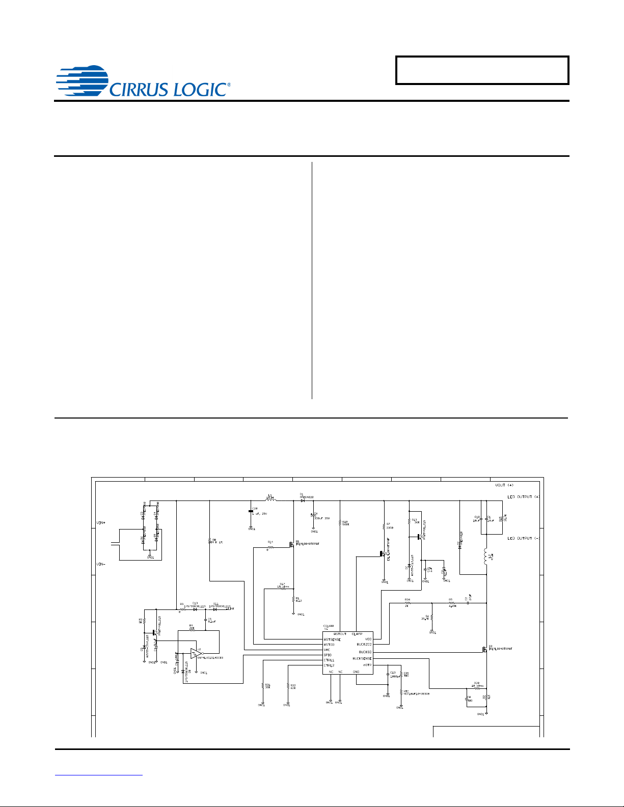
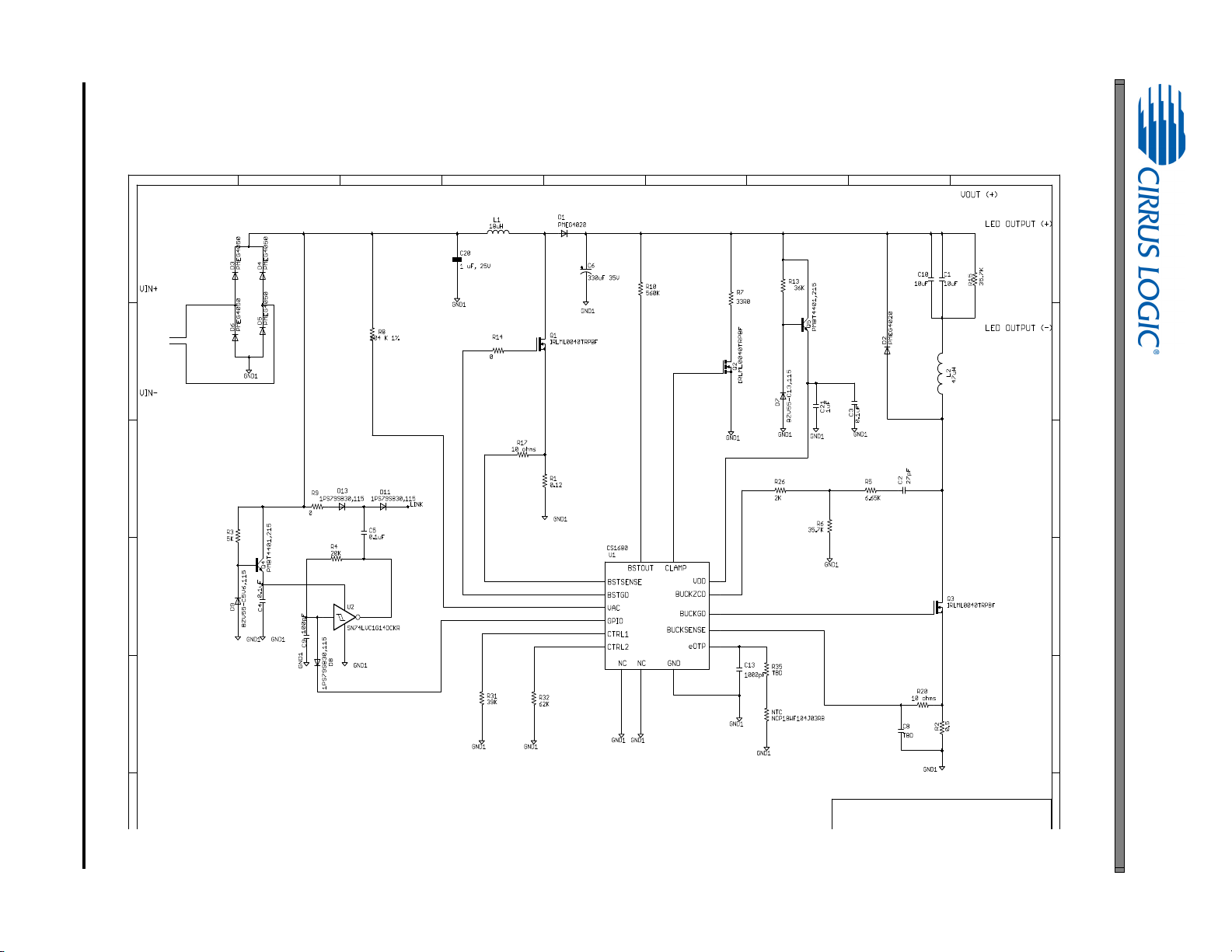
2. SCHEMATIC
AN405
Figure 1. Schematic
Page 5

3. BILL OF MATERIALS
C2
C3, C4, C5
C6
C9
C20
C21
C13
D1-D2
D3-D6
D7
D9
D8, D11, D13
L1
L2
NTC
Q1, Q2, Q3
Q4, Q5
R1
R2
R3
R4
R5
R7
R8
R9,R14
R10
R17,R20
R26
R6, R15
R31
R13
R32
U1
Table 1: Bill of Materials
Designator Value Manufacturer Part Number
C1, C10 CAP CER 10UF 25V 10% X7R 1206 Taiyo Yuden TMK316B7106KL-TD
U2 IC SGL SCHMT-TRIG INVERT SC70-5 Texas Instruments SN74LVC1G14DCKR
AN405
CAP CER 27PF 50V 5% NP0 0603 TDK Corporation C1608C0G1H270J080AA
CAP CER 0.1UF 25V 10% X7R 0603 Murata Electronics North America GRM188R71E104KA01D
CAP ALUM 330UF 35V 20% RADIAL Panasonic EEU-fm1v331
CAP CER 100PF 50V 5% NP0 0603 TDK Corporation C1608C0G1H101J080AA
CAP CER 0.68UF 25V 10% X7R 0603 TDK Corporation CGA3E1X7R1E684K080AC
CAP CER 1UF 25V 10% X7R 0603 Taiyo Yuden TMK107B7105KA-T
CAP CER 1000PF 50V 10% X7R 0603 Murata Electronics North America GRM188R71H102KA01D
DIO DE SC HO TTK Y 40V 2A SO D1 28 NXP Se mico nductors PMEG4020EP,115
DIO DE SC HO TTK Y 30V 3A SO D1 28 NXP Se mico nductors PMEG3030EP,115
DIODE ZENER 13V 500MW SOD80C NXP Semiconductors BZV55-C13 ,1 15
DIODE ZENER 6.2V 500MW LLDS NXP Semiconductors BZV55-C6V2, 115
DIODE SCHOTTKY 40V 200MA SOD523 NXP Semiconductors 1PS7 9SB30 ,1 15
INDUCTOR POWER 18UH 2.4A SMD Abracon ASPI-8040S-180M-TCT-ND
INDUCTOR 47UH 1.4A 20% SMD TDK Corporation VLP6045LT-470M
THERMISTOR 100K OHM NTC 0603 SMD Murata Electronics North America NCP18WF104J03RB
MOSFET N-CH 40V 3.6A SOT-23-3 International Rectifier IRLML0040TRPBF
TRANS NPN SW 600MA 40V SOT23 NXP Semiconductors PMBT4401,215
RES .12 OHM 1/4W 1% 0805 SMD Rohm Semiconducto r MC R1 0EZHFLR1 20
RES .5 OHM 1/4W 1% 0805 SMD Stackpole CSR0805FKR500CT-ND
RES 4.99K OHM 1/10W 1% 0603 SMD Yageo RC0603FR-074K99L
RES 20K OHM 1/10W 5% 0603 SMD Yageo RC0603JR-0720KL
RES 6.65K OHM 1/10W 1% 0603 SMD Yageo RC0603FR-076K65L
RES 33 OHM 2W 5% METAL FILM AX Yageo FMP200JR-52-33R
RES 604K OHM 1/10W 1% 0603 SMD Yageo RC0603FR-07604KL
RES 0.0 OHM 1/10W 0603 SMD Yage o RC0603JR-070RL
RES 560K OHM 1/10W 1% 0603 SMD Yageo RC0603FR-07560KL
RES 10.0 OHM 1/10W 1% 0603 SMD Yageo RC0603FR-0710RL
RES 2.0K OHM 1/10W 5% 0603 SMD Yageo RC0603JR-072KL
RES 35.7K OHM 1/10W 1% 0603 SMD Yageo RC0603FR-0735K7L
RES 39K OHM 1/10W 1% 0603 SMD Yageo RC0603FR-0739KL
RES 42.2K OHM 1/10W 1% 0603 SMD Yageo RC0603FR-0742K2L
RES 62K OHM 1/10W 1% 0603 SMD Yageo RC0603FR-0762KL
CS1680
5
Page 6

6
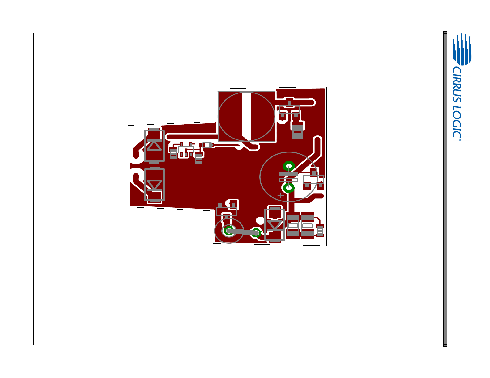
4. BOARD LAYOUT
Figure 2. Top Silkscreen
AN405
Page 7
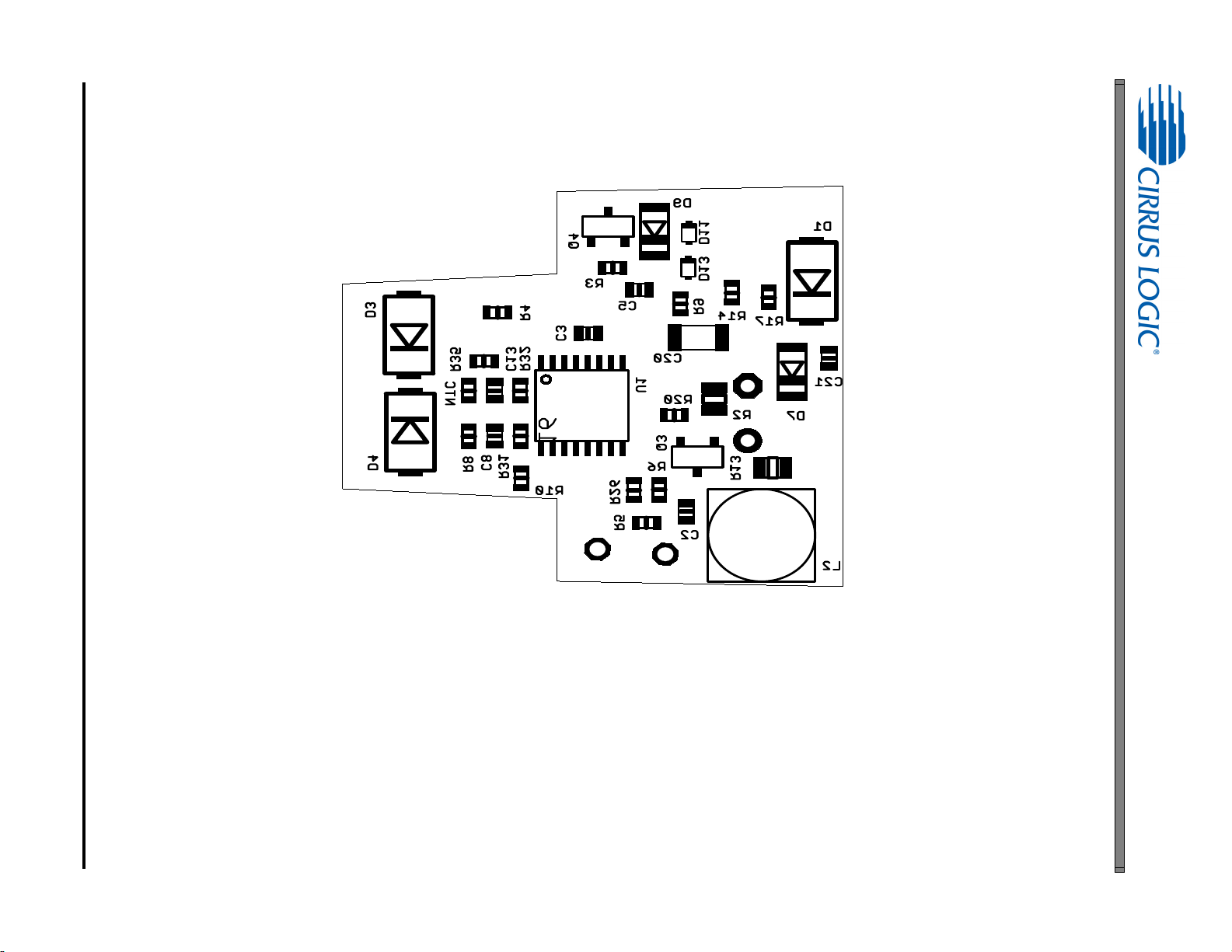
Figure 3. Bottom Silkscreen
AN405
7
Page 8
8
Figure 4. Top Routing
AN405
Page 9

Figure 5. Bottom Routing
AN405
9
Page 10

5. DIMMER COMPATIBILITY
Lamp with a (CS1680 120V/60 Hz)
Date 09/09/2013 Power Factor
Vendor Cirrus Logic EN55015 Compliant (Y/N)
Input Voltage 12VAC Nominal Input Power (W)
Form Factor MR16 Maximum Input Power (W)
Model # CRD1680-10W-18V Output Voltage (V)
IC CS1680 Output Current (mA)
Topology Boost/Buck Output Current Ripple 120Hz (mA)
Isolation (Y/ N) N Output Power (W)
Efficiency (%)
82%
1,4
1,4
1,4
1,2
1,2
1,4
1,3
AN405
0.93
N
9.46
10
18V
433
NA
7.79
Dimmer
5
No Dimmer
Regular Switch
Lutron
DVLV-600P
Leading Edge
Lutron 6613
Leading Edge
Lutron
DVELV-300P
Leading Edge
Lutron
SELV-300P
Trailing Edge
Leviton 6615
Trailing Edge
Flicker Free Steady State
# of lamps # of lamps # of lamps # of lamps # of lamps # of lamps
Transfomer
111111
Lightech LET60 Y Y Y Y Y Y
Lightech LET75 Y N Y Y Y Y
Hatch RS12-80M Y Y N Y Y Y
Hatch VS12-60WD Y Y Y Y Y Y
Osram ET-MZ60 Y Y N Y Y Y
Eurofase Y N N Y Y Y
Table 2: 120VAC, 60HZ Mains Power System
1. Tested at nominal input voltage, nominal input frequency and without a dimmer after soaking for 15 minutes
2. Average
3. Peak-to-peak
4. Measured with Chroma 66202 Power Analyzer
5. This document includes trademarks, trade names, brands, logos, product names and/or product identifiers of companies other
than Cirrus Logic, Inc. All such trademarks, trade names, brands, logos, product names, and product identifiers are for
identification purposes only and are the property of their respective owners, who are not affiliated with Cirrus Logic. Please visit
the respective sites of those owners to obtain a listing or understanding of their trademark rights. This document also includes
results from testing performed by Cirrus Logic for its own purposes and for which there are currently no industry standards. While
this testing was applied objectively, its results may include at least some degree of subjectivity. The testing or test results should
not be interpreted as any comment on the overall quality or suitability of any tested products
Table 2 reports the empirical dimmer compatibility results when detectable inputs to the dimmer compatibility circuit
are generated using a 120VAC transformer paired with a leading edge or trailing edge dimmer.
10
Page 11
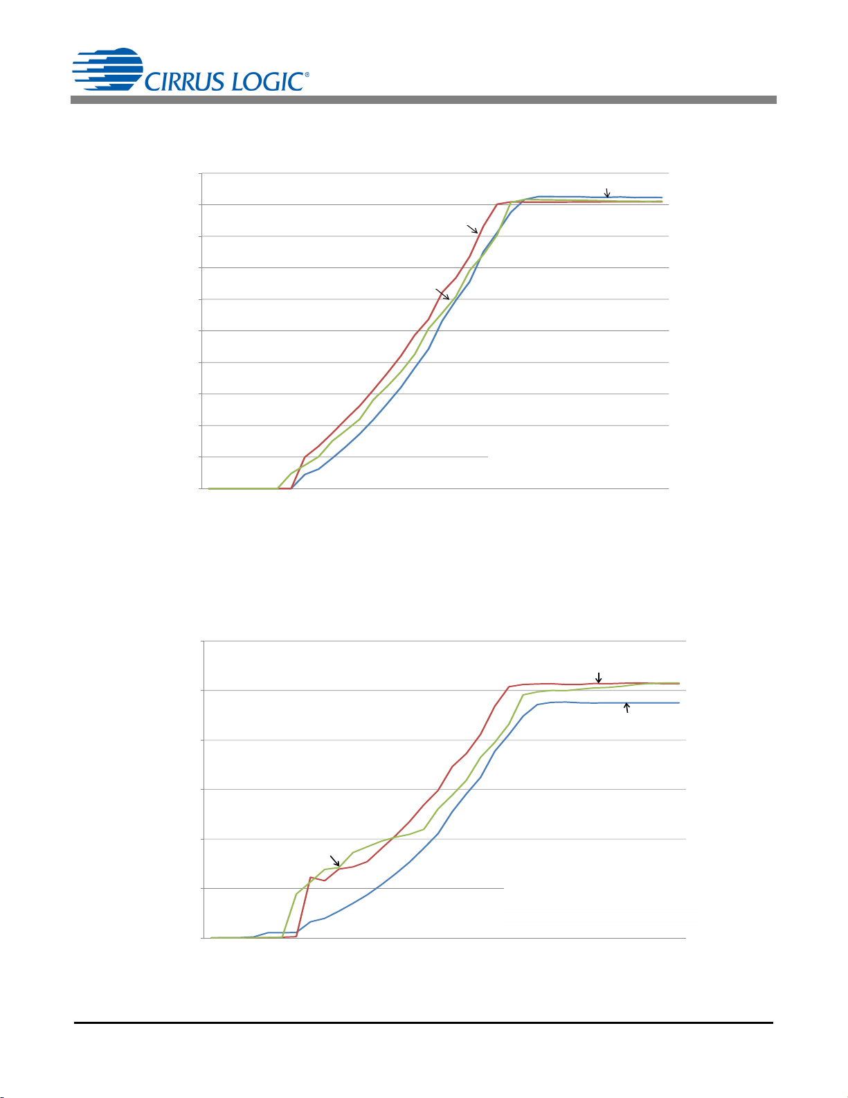
6. PERFORMANCE PLOTS
0
0.05
0.1
0.15
0.2
0.25
0.3
0.35
0.4
0.45
0.5
15 30 45 60 75 90 105 120 135 150 165 180
Output Current (A)
Dim Angle (ƕ)
Mode 1 - Hatch LS1250EN w/Leading-edge Waveform
Mode 2 - Lightech LET60 w/Leading-edge Waveform
Mode 3 – Lightech LED60 w/Trailing-edge Waveform
Figure 6. Output Current vs. Dim Angle
Figure 7. Input Power vs. Dim Angle
AN405
Mode 1
Mode 2
Mode 3
12
10
8
6
Input Power (W)
4
2
0
15 30 45 60 75 90 105 120 135 150 165 180
Mode 3
Dim Angle (ƕ)
Mode 2
Mode 1
Mode 1 - Hatch LS1250EN w/Leading-edge Waveform
Mode 2 - Lightech LET60 w/Leading-edge Waveform
Mode 3 – Lightech LED60 w/Trailing-edge Waveform
11
Page 12

0.47
Figure 8. Output Current vs. Line Voltage
Figure 9. Efficiency vs. Line Voltage
0.46
0.45
0.44
0.43
0.42
0.41
Output Current (A)
0.39
AN405
Mode 1
Mode 2
0.4
0.38
0.37
108 110 112 114 116 118 120 122 124 126 128 130 132
86
84
82
80
78
76
Efficiency (%)
74
Mode 1 - Hatch LS1250EN (Magnetic Transformer)
Mode 2 - Lightech LET60 (Electronic Transformer)
Line Voltage (V)
Mode 1
Mode 2
72
70
68
108 110 112 114 116 118 120 122 124 126 128 130 132
Mode 1 - Hatch LS1250EN (Magnetic Transformer)
Mode 2 - Lightech LET60 (Electronic Transformer)
Line Voltage (V)
12
Page 13

7. REVISION HISTORY
Revision Date Changes
RD1 AUG 2014 Preliminary release
AN405
13
 Loading...