

Page 1
CRD1616A-11W-30V
AN404
Design Example of CS1616A
for 11W Dimmer-Compatible SSL Circuit
Features
• Supports Cirrus Logic CS1616A
• Quasi-resonant Flyback Topology with Constantcurrent Output
• Flicker-free Dimming
• Line Voltage: 207VAC - 253VAC
• Rated Input Power: 11W
• Rated Output Power: 5W
• Efficiency: ~82% at 300mA for 10xLEDs in Series
• Low Component Count
General Description
This application note provides an example of a Solid State
Lighting (SSL) LED lamp circuit designed using Cirrus
Logic’s CS1616A, the CRD1616A-11W-30V. The
CRD1616A-11W-30V reference design demonstrates the
performance of the CS1616A resonant mode AC/DC LED
driver IC with a 300mA output driving
It offers best-in-class dimmer compatibility and minimum
dimming performance with leading-edge, trailing-edge, and
digital dimmers. The form factor is targeted to fit into many
LED bulb applications (A19-type, PAR).
10xLEDs in series
.
Cirrus Logic, Inc.
http://www.cirrus.com
Copyright Cirrus Logic, Inc. 2014
(All Rights Reserved)
AUG‘14
AN404
Page 2
AN404
Contacting Cirrus Logic Support
For all product questions and inquiries contact a Cirrus Logic Sales Representative. To find the one nearest to you
go to www.cirrus.com
IMPORTANT NOTICE
Cirrus Logic, Inc. and its subsidiaries ("Cirrus") believe that the information contained in this document is accurate and reliable. However, the information is subject
to change without notice and is provided "AS IS" without warranty of any kind (express or implied). Customers are advised to obtain the latest version of relevant
information to verify, before placing orders, that information being relied on is current and complete. All products are sold subject to the terms and conditions of sale
supplied at the time of order acknowledgment, including those pertaining to warranty, indemnification, and limitation of liability. No responsibility is assumed by Cirrus
for the use of this information, including use of this information as the basis for manufacture or sale of any items, or for infringement of patents or other rights of third
parties. This document is the property of Cirrus and by furnishing this information, Cirrus grants no license, express or implied under any patents, mask work rights,
copyrights, trademarks, trade secrets or other intellectual property rights. Cirrus owns the copyrights associated with the information contained herein and gives
consent for copies to be made of the information only for use within your organization with respect to Cirrus integrated circuits or other products of Cirrus. This consent does not extend to other copying such as copying for general distribution, advertising or promotional purposes, or for creating any work for resale.
CERTAIN APPLICATIONS USING SEMICONDUCTOR PRODUCTS MAY INVOLVE POTENTIAL RISKS OF DEATH, PERSONAL INJURY, OR SEVERE PROPERTY OR ENVIRONMENTAL DAMAGE ("CRITICAL APPLICATIONS"). CIRRUS PRODUCTS ARE NOT DESIGNED, AUTHORIZED OR WARRANTED FOR
USE IN PRODUCTS SURGICALLY IMPLANTED INTO THE BODY, AUTOMOTIVE SAFETY OR SECURITY DEVICES, LIFE SUPPORT PRODUCTS OR OTHER
CRITICAL APPLICATIONS. INCLUSION OF CIRRUS PRODUCTS IN SUCH APPLICATIONS IS UNDERSTOOD TO BE FULLY AT THE CUSTOMER'S RISK
AND CIRRUS DISCLAIMS AND MAKES NO WARRANTY, EXPRESS, STATUTORY OR IMPLIED, INCLUDING THE IMPLIED WARRANTIES OF MERCHANTABILITY AND FITNESS FOR PARTICULAR PURPOSE, WITH REGARD TO ANY CIRRUS PRODUCT THAT IS USED IN SUCH A MANNER. IF THE CUSTOMER
OR CUSTOMER'S CUSTOMER USES OR PERMITS THE USE OF CIRRUS PRODUCTS IN CRITICAL APPLICATIONS, CUSTOMER AGREES, BY SUCH USE,
TO FULLY INDEMNIFY CIRRUS, ITS OFFICERS, DIRECTORS, EMPLOYEES, DISTRIBUTORS AND OTHER AGENTS FROM ANY AND ALL LIABILITY, INCLUDING ATTORNEYS' FEES AND COSTS, THAT MAY RESULT FROM OR ARISE IN CONNECTION WITH THESE USES.
Cirrus Logic, Cirrus, the Cirrus Logic logo designs, EXL Core, and the EXL Core logo design are trademarks of Cirrus Logic, Inc. All other brand and product names
in this document may be trademarks or service marks of their respective owners.
IMPORTANT SAFETY INSTRUCTIONS
Read and follow all safety instructions prior to using this demonstration board.
This Engineering Evaluation Unit or Demonstration Board must only be used for assessing IC performance in a
laboratory setting. This product is not intended for any other use or incorporation into products for sale.
This product must only be used by qualified technicians or professionals who are trained in the safety procedures
associated with the use of demonstration boards.
Risk of Electric Shock
• The direct connection to the AC power line and the open and unprotected boards present a serious risk of electric
shock and can cause serious injury or death. Extreme caution needs to be exercised while handling this board.
• Avoid contact with the exposed conductor or terminals of components on the board. High voltage is present on
exposed conductor and it may be present on terminals of any components directly or indirectly connected to the AC
line.
• Dangerous voltages and/or currents may be internally generated and accessible at various points across the board.
• Charged capacitors store high voltage, even after the circuit has been disconnected from the AC line.
• Make sure that the power source is off before wiring any connection. Make sure that all connectors are well
connected before the power source is on.
• Follow all laboratory safety procedures established by your employer and relevant safety regulations and guidelines,
such as the ones listed under, OSHA General Industry Regulations - Subpart S and NFPA 70E.
Suitable eye protection must be worn when working with or around demonstration boards. Always
comply with your employer’s policies regarding the use of personal protective equipment.
All components and metallic parts may be extremely hot to touch when electrically active.
2
Page 3
AN404
1. INTRODUCTION
The CS1616A is a 230VAC quasi-resonant flyback mode dimmable LED controller IC. The CS1616A uses a digital
control algorithm that is optimized for high efficiency and > 0.90 power factor over an input voltage range (207VAC
- 253VAC). The CS1616A integrates a dimmer compatibilty circuit with a constant output current, quasi-resonant
flyback stage. An adaptive dimmer compatibility algorithm controls the dimmer compatibility operation mode to enable flicker-free operation from 0% to 100% output current with leading-edge, trailing-edge, and digital dimmers.
The CRD1616A-11W-30V board is optimized to deliver low system cost in a high-efficiency, flicker-free, phasedimmable, solid-state lighting (SSL) solution for incandescent lamp replacement applications. The feedback loop is
closed through an integrated digital control system within the IC. Protection algorithms such as output open/short,
current-sense resistor open/ short, and overtemperature thermistors protect the system during abnormal conditions.
Details of these features are provided in the CS1616A data sheet.
The CRD1616A-11W-30V board demonstrates the performance of the CS1616A. This reference board has been
designed for an output load of 10xLEDs in series at 300mA (
This data sheet provides the schematic and PCB layout for the reference design board. The performance graphs
demonstrate the performance of the CS1616A dimmable-controller reference design in terms of Efficiency vs. Line
Voltage, Power Factor vs. Line Voltage, THD vs. Line Voltage, and Output Current vs. Line Voltage. Extreme caution
needs to be exercised while handling this board. This board is to be used by trained professionals only.
30V typical).
3
Page 4
4
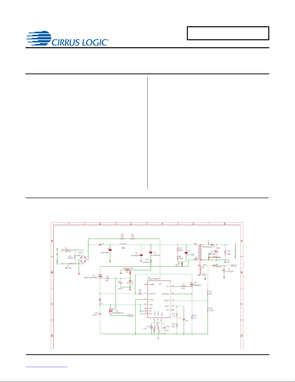
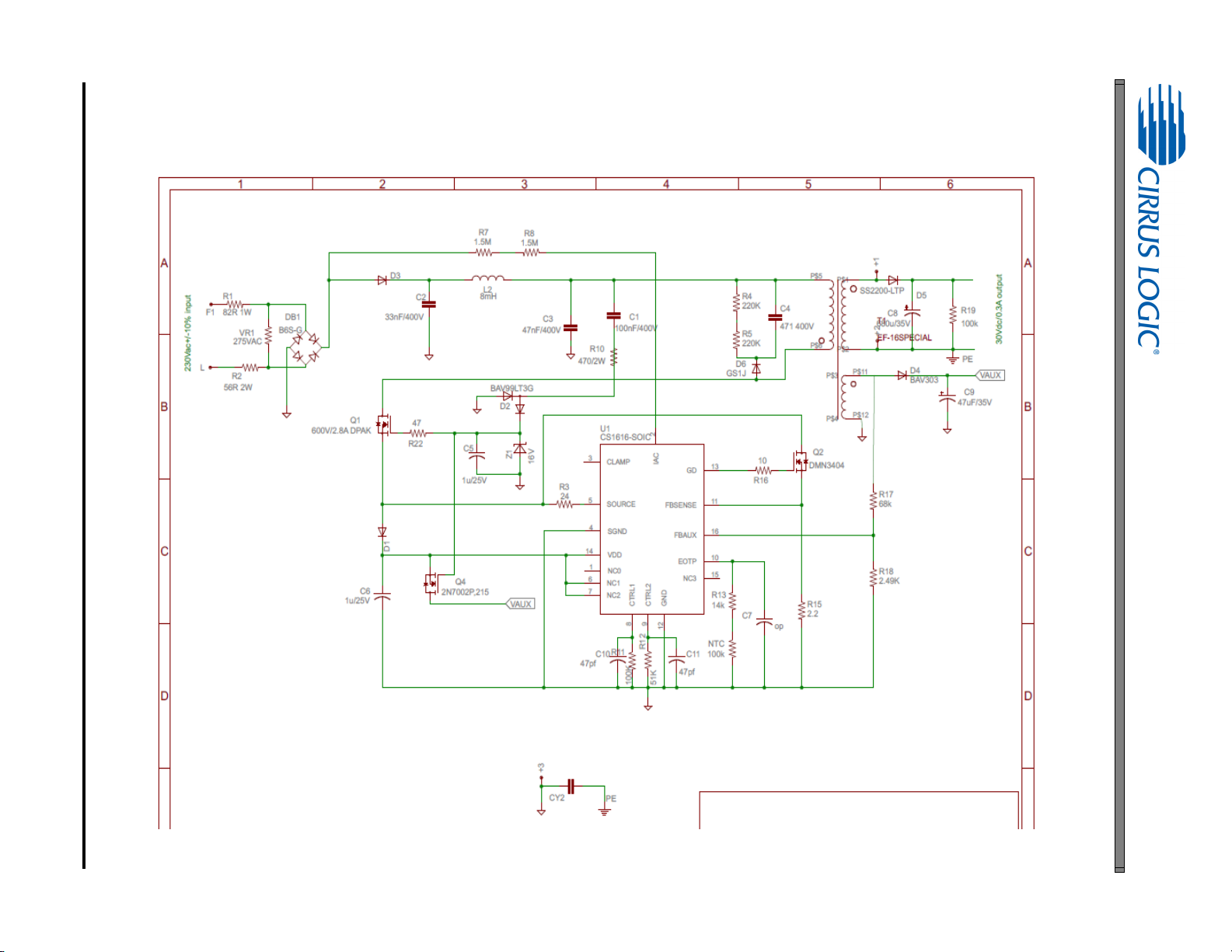
2. SCHEMATIC
Figure 1. Schematic
AN404
Page 5
3. BILL OF MATERIALS
Part Value Package Part Value Package
C1 100nF/400V CBB104-10*4.5 Q4 2N7002P,215 SOT23
C3 68nF/400V CBB104-10*4.5 R2 47R 2W 0309V-SS
C4 471 400V C1206 R3 24 R0805
C5 1u/25V C0603 R4 220K R0805
C6 1u/25V C0603 R5 220K R0805
C8 680u/35V CAP-E20-10 R8 1.5M R1206
C10 47pf/25V C0603 R11 102K R0603
C11 47pf/25V C0603 R12 51K R0603
D1 1N4148 SOD123 R15 2.2R 1% R0805
D2 BAV99LT3G SOT23 R16 10 R0603
D3 UF4007 M7 R17 68k R0603
D4 BAV303 SOD123 R18 2.49K R0603
D6 GS1J SMA R22 47 R0603
DB1 B6S-G MBS T1 EF-16SPECIAL KEE
L2 8mH DR0805 U1 CS1616A-SOIC CS1616A-SOIC
NTC 100k R0603 VR1 275VAC 0204/5
Q2 DMN3404 SOT23
Table 1: Bill of Materials
C2 33nF/400V CBB104-10*4.5 R1 47R 2W FUSE-RESISTOR
C7 47pf/25V C0603 R7 1.5M R1206
C9 47uF/35V RB-5*12 R10 470/2W 0309V-SS
CY2 2.2nF YC10MM R13 15.4k R0603
AN404
D5 SS2200-LTP M7 R19 100k R0805
Q1 600V/2.8A DPAK Z1 16V NZH16C,115
5
Page 6

6
4. BOARD LAYOUT
Figure 2. Top Silkscreen
AN404
Page 7

Figure 3. Bottom Silkscreen
AN404
7
Page 8

8
Figure 4. Top Routing
AN404
Page 9

Figure 5. Bottom Routing
AN404
9
Page 10
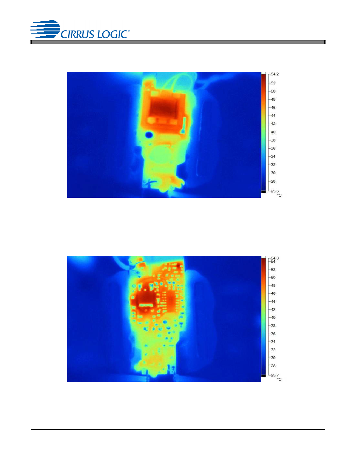
5. THERMAL IMAGING
Figure 6. Top Thermal
Figure 7. Bottom Thermal
AN404
10
Page 11
6. DIMMER COMPATIBILITY
Lamp with a CS1616A (230V/50Hz)
Date 9/26/2013 Power Factor
Vendor Cirrus Logic EN55015 Compliant (Y/N)
Input Voltage 230V/50Hz Nominal Input Power (W)
Form Factor NA Maximum Input Power (W)
Model # CRD1616A-11W-30V Output Voltage (V)
IC CS1616A Output Current (mA)
Topology Flyback Output Current Ripple 120Hz (mA)
Isolation (Y/ N) Y Output Power (W)
Efficiency (%)
84.3%
1,4
1,4
1,4
1,2
1,2
1,4
1,3
AN404
0.9566
N
10.28
11
30.943V
280
NA
8.664
Dimmer
5
Manufacture Type
Berker 286110
Bticino N4407
Bull 500W
Busch 2247U
Busch 6513U
Busch 6519U
Chint New7-6305
Chisen
Chisen 350W
Clipsal 32E450UDM
Clipsal EV51RD400
CLSEN QSY626W
Cshyh 150W
Dbang
Futina 250W
HPM 400T
HPM 250L
HPM 250T
HPM 700L
HPM 400L
HPM 1000L
HPM XL250T
HPM XL700L
Universal
Leading Edge
Leading Edge
Leading Edge
Trailing Edge
Trailing Edge
Leading Edge
Leading Edge
Leading Edge
Universal
Leading Edge
Leading Edge
Leading Edge
Leading Edge
Leading Edge
Trailing Edge
Leading Edge
Trailing Edge
Leading Edge
Leading Edge
Leading Edge
Trailing Edge
Leading Edge
Flicker Free
Steady-State
Monotonic
Dimming
Max I
(mA) Min I
out
out
(mA)
# of lamps # of lamps # of lamps # of lamps
11 1 1
YY 280 9
NN 7 3
YY 277 8
YY 277 9
YY 301 11
YN 280 8
NY 280 8
YY 277 8
YY 277 8
NY 287 10
YY 278 8
YY 277 8
YY 278 8
YY 278 8
NY 281 11
YY 276 8
NY 253 2
YY 270 7
YY 224 7
NY 261 2
NY 258 1
NY 256 2
YY 253 7
11
Page 12

AN404
Dimmer
5
Manufacture Type
HPM XL1000T
HPM LN250T
Jung 1254UDE
Legrand 67085
Leiben 450W
Lonon NB 50.OTG
Lutron LLSI-502
Lutron LLSM-502
Merten 5725
Merten 5771
MK 52471SL
N&L 28985
Opus 852.390
Opus 852.392
KOPP 8078
Songri 400W
T&J K211-1KM2
T&J K211-M2
TCL LM2
TNC Z26-M12
Wuyun W13-C162
Berker 2875
Jung 225NVDE
Busch 6517U-101
Berker 2819
Duwi DW700DA
1. Tested at nominal input voltage, nominal input frequency and without a dimmer after soaking for 15 minutes
2. Average
3. Peak-to-peak
4. Measured with Chroma 66202 Power Analyzer
5. This document includes trademarks, trade names, brands, logos, product names and/or product identifiers of companies other
than Cirrus Logic, Inc. All such trademarks, trade names, brands, logos, product names, and product identifiers are for
identification purposes only and are the property of their respective owners, who are not affiliated with Cirrus Logic. Please visit
the respective sites of those owners to obtain a listing or understanding of their trademark rights. This document also includes
results from testing performed by Cirrus Logic for its own purposes and for which there are currently no industry standards. While
this testing was applied objectively, its results may include at least some degree of subjectivity. The testing or test results should
not be interpreted as any comment on the overall quality or suitability of any tested products
Trailing Edge
Trailing Edge
Leading Edge
Trailing Edge
Leading Edge
Leading Edge
Leading Edge
Leading Edge
Leading Edge
Trailing Edge
Leading Edge
Trailing Edge
Leading Edge
Leading Edge
Trailing Edge
Leading Edge
Leading Edge
Leading Edge
Leading Edge
Leading Edge
Trailing Edge
Leading Edge
Leading Edge
Leading Edge
Leading Edge
Leading Edge
Flicker Free
Steady-State
Monotonic
Dimming
Max I
(mA) Min I
out
out
(mA)
# of lamps # of lamps # of lamps # of lamps
11 1 1
YY 270 7
NY 258 8
YY 307 10
YY 281 2
YY 278 8
YY 277 8
YY 281 8
YY 266 8
YY 277 8
YY 257 8
YY 277 8
YN 257 8
YY 277 8
YY 278 8
YY 281 9
YY 277 8
NY 277 8
YY 278 8
YY 273 8
YY 277 8
YY 277 9
YY 277 8
YY 277 8
YY 277 7
YY 277 7
YY 277 8
12
Page 13

7. PERFORMANCE PLOTS
0.26
0.27
0.28
0.29
0.3
0.31
207 215 223 230 237 245 253
ILED Current (A)
Line Voltage (V)
Figure 8. Output Current vs. Line Voltage
80
81
82
83
84
85
86
87
88
89
90
207 215 223 230 237 245 253
Efficiency(%)
Line Voltage (V)
Figure 9. Typical Efficiency vs. Line Voltage
AN404
13
Page 14

AN404
0.9
0.91
0.92
0.93
0.94
0.95
0.96
0.97
0.98
0.99
1
207 215 223 230 237 245 253
Power Factor
Line Voltage (V)
Figure 10. Power Factor vs. Line Voltage
0
0.05
0.1
0.15
0.2
0.25
0.3
0.35
30 55 80 105 130 155 180
LED Current (A)
Dim Angle
0
1
Leading Edge
Trailing Edge
Figure 11. Output Current vs. Dim Angle
14
Page 15

8. REVISION HISTORY
Revision Date Changes
RD1 AUG 2014 Preliminary release
AN404
15
 Loading...