

Page 1
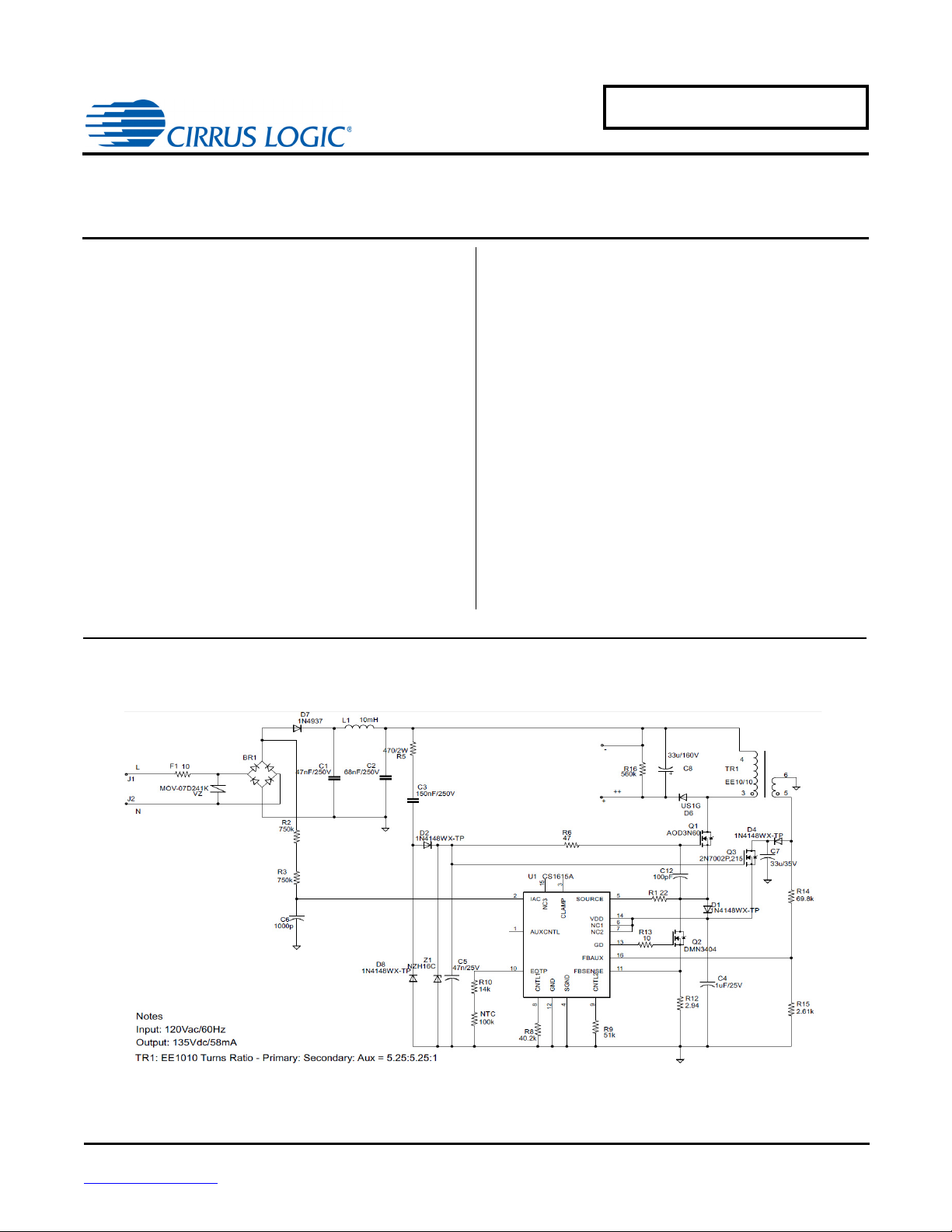
CRD1615A-8W-125V Schematic
AN402
Design Example of CS1615A
for 8.5W Dimmer-Compatible SSL Circuit
Features
• Supports Cirrus Logic CS1615A
• Quasi-resonant Buck-Boost Topology with Constantcurrent Output
• Flicker-free Dimming
• Line Voltage: 108VAC -132VAC
• Rated Input Power: 8.5W
• Rated Output Power: 7.83W
• Efficiency: ~88% at 58mA for 42xLEDs in Series
• Low Component Count
General Description
This application note provides an example of a Solid State
Lighting (SSL) LED lamp circuit designed using Cirrus
Logic’s CS1615A, the CRD1615A-8W-125V. The
CRD1615A-8W-125V reference design demonstrates the
performance of the CS1615A resonant mode AC/DC LED
driver IC with a 58mA output driving
offers best-in-class dimmer compatibility and minimum
dimming performance with leading-edge, trailing-edge, and
digital dimmers. The form factor is targeted to fit into many
LED bulb applications (A19-type, PAR).
42xLEDs in series
. It
Cirrus Logic, Inc.
http://www.cirrus.com
Copyright Cirrus Logic, Inc. 2014
(All Rights Reserved)
AUG‘14
AN402
Page 2
AN402
Contacting Cirrus Logic Support
For all product questions and inquiries contact a Cirrus Logic Sales Representative. To find the one nearest to you
go to www.cirrus.com
IMPORTANT NOTICE
Cirrus Logic, Inc. and its subsidiaries ("Cirrus") believe that the information contained in this document is accurate and reliable. However, the information is subject
to change without notice and is provided "AS IS" without warranty of any kind (express or implied). Customers are advised to obtain the latest version of relevant
information to verify, before placing orders, that information being relied on is current and complete. All products are sold subject to the terms and conditions of sale
supplied at the time of order acknowledgment, including those pertaining to warranty, indemnification, and limitation of liability. No responsibility is assumed by Cirrus
for the use of this information, including use of this information as the basis for manufacture or sale of any items, or for infringement of patents or other rights of third
parties. This document is the property of Cirrus and by furnishing this information, Cirrus grants no license, express or implied under any patents, mask work rights,
copyrights, trademarks, trade secrets or other intellectual property rights. Cirrus owns the copyrights associated with the information contained herein and gives
consent for copies to be made of the information only for use within your organization with respect to Cirrus integrated circuits or other products of Cirrus. This consent does not extend to other copying such as copying for general distribution, advertising or promotional purposes, or for creating any work for resale.
CERTAIN APPLICATIONS USING SEMICONDUCTOR PRODUCTS MAY INVOLVE POTENTIAL RISKS OF DEATH, PERSONAL INJURY, OR SEVERE PROPERTY OR ENVIRONMENTAL DAMAGE ("CRITICAL APPLICATIONS"). CIRRUS PRODUCTS ARE NOT DESIGNED, AUTHORIZED OR WARRANTED FOR
USE IN PRODUCTS SURGICALLY IMPLANTED INTO THE BODY, AUTOMOTIVE SAFETY OR SECURITY DEVICES, LIFE SUPPORT PRODUCTS OR OTHER
CRITICAL APPLICATIONS. INCLUSION OF CIRRUS PRODUCTS IN SUCH APPLICATIONS IS UNDERSTOOD TO BE FULLY AT THE CUSTOMER'S RISK
AND CIRRUS DISCLAIMS AND MAKES NO WARRANTY, EXPRESS, STATUTORY OR IMPLIED, INCLUDING THE IMPLIED WARRANTIES OF MERCHANTABILITY AND FITNESS FOR PARTICULAR PURPOSE, WITH REGARD TO ANY CIRRUS PRODUCT THAT IS USED IN SUCH A MANNER. IF THE CUSTOMER
OR CUSTOMER'S CUSTOMER USES OR PERMITS THE USE OF CIRRUS PRODUCTS IN CRITICAL APPLICATIONS, CUSTOMER AGREES, BY SUCH USE,
TO FULLY INDEMNIFY CIRRUS, ITS OFFICERS, DIRECTORS, EMPLOYEES, DISTRIBUTORS AND OTHER AGENTS FROM ANY AND ALL LIABILITY, INCLUDING ATTORNEYS' FEES AND COSTS, THAT MAY RESULT FROM OR ARISE IN CONNECTION WITH THESE USES.
Cirrus Logic, Cirrus, the Cirrus Logic logo designs, EXL Core, and the EXL Core logo design are trademarks of Cirrus Logic, Inc. All other brand and product names
in this document may be trademarks or service marks of their respective owners.
IMPORTANT SAFETY INSTRUCTIONS
Read and follow all safety instructions prior to using this demonstration board.
This Engineering Evaluation Unit or Demonstration Board must only be used for assessing IC performance in a
laboratory setting. This product is not intended for any other use or incorporation into products for sale.
This product must only be used by qualified technicians or professionals who are trained in the safety procedures
associated with the use of demonstration boards.
Risk of Electric Shock
• The direct connection to the AC power line and the open and unprotected boards present a serious risk of electric
shock and can cause serious injury or death. Extreme caution needs to be exercised while handling this board.
• Avoid contact with the exposed conductor or terminals of components on the board. High voltage is present on
exposed conductor and it may be present on terminals of any components directly or indirectly connected to the AC
line.
• Dangerous voltages and/or currents may be internally generated and accessible at various points across the board.
• Charged capacitors store high voltage, even after the circuit has been disconnected from the AC line.
• Make sure that the power source is off before wiring any connection. Make sure that all connectors are well
connected before the power source is on.
• Follow all laboratory safety procedures established by your employer and relevant safety regulations and guidelines,
such as the ones listed under, OSHA General Industry Regulations - Subpart S and NFPA 70E.
Suitable eye protection must be worn when working with or around demonstration boards. Always
comply with your employer’s policies regarding the use of personal protective equipment.
All components and metallic parts may be extremely hot to touch when electrically active.
2
Page 3
AN402
1. INTRODUCTION
The CS1615A is a 120VAC quasi-resonant buck-boost mode dimmable LED controller IC. The CS1615A uses a
digital control algorithm that is optimized for high efficiency and > 0.90 power factor over an input voltage range
(108VAC -132VAC). The CS1615A integrates a dimmer compatibilty circuit with a constant output current, quasiresonant flyback stage. An adaptive dimmer compatibility algorithm controls the dimmer compatibility operation
mode to enable flicker-free operation from 0% to 100% output current with leading-edge, trailing-edge, and digital
dimmers.
The CRD1615A-8W-125V board is optimized to deliver low system cost in a high-efficiency, flicker-free, phasedimmable, solid-state lighting (SSL) solution for incandescent lamp replacement applications. The feedback loop is
closed through an integrated digital control system within the IC. Protection algorithms such as output open/short,
current-sense resistor open/ short, and overtemperature thermistors protect the system during abnormal conditions.
Details of these features are provided in the CS1615A data sheet.
The CRD1615A-8W-125V board demonstrates the performance of the CS1615A. This reference board has been
designed for an output load of 42xLEDs in series at 58mA (
This data sheet provides the schematic and PCB layout for the reference design board. The performance graphs
demonstrate the performance of the CS1615A dimmable-controller reference design in terms of Efficiency vs. Line
Voltage, Power Factor vs. Line Voltage, THD vs. Line Voltage, Output Current vs. Line Voltage, and Output Current
vs. Dim Angle.
125V typical).
Extreme caution needs to be exercised while handling this board. This board is to be used by trained professionals
only.
3
Page 4
4
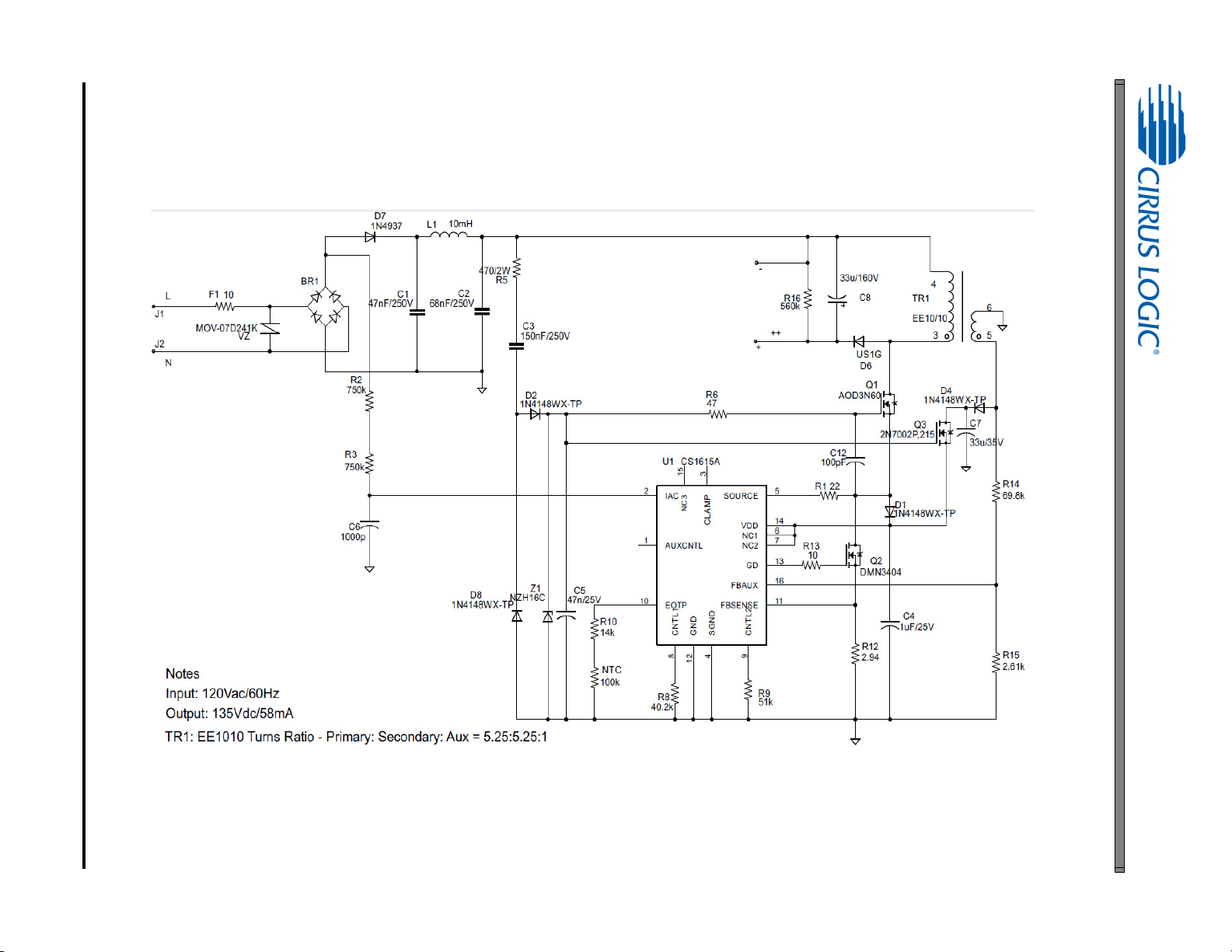
2. SCHEMATIC
Figure 1. Schematic
AN402
Page 5
AN402
Table 1: Bill of Materials
3. BILL OF MATERIALS
Ref Descript Part # Manufacturer
BR1 DIODE RECT 200V 0.8A NPB MINIDIP HD02-T DIODES INC
C1 CAP FILM 0.047UF 250VDC RADIAL B32529C3473K EPCOS Inc
C2 CAP FILM 0.068UF 250VDC RADIAL ECQ-E2683KB Panasonic
C3 CAP FILM 0.15UF 250VDC RADIAL B32529C3154K289 EPCOS Inc
C4 CAP CER 1UF 25V 10% X7R 0805 C2012X7R1E105K125AB TDK Corporation
C5 CAP CER 0.047UF 25V 10% X7R 0603 C1608X7R1E473K TDK Corporation
C6 CAP CER 1000PF 50V 10% X7R 0603 VJ0603Y102KXAAC31 Vishay Vitramon
C7 CAP ALUM 33UF 35V 20% RADIAL ECA-1VHG330 Panasonic Electronic Components
C8 CAP ALUM 33UF 160V 20% RADIAL UCY2C330MPD1TD Nichicon
C12 CAP CER 100PF 50V 10% X7R 0603 VJ0603Y101KXACW1BC Vishay Vitramon
D1, D2, D4, D8 DIODE SWITCH 75V 300MA SOD323 1N4148WX-TP MICRO COMMERCIAL
D6 DIODE ULTRA FAST 400V 1A SMA US1G-13-F Diodes Inc
D7 DIODE FAST REC 600V 1A DO204AL 1N4937-E3/54 Vishay Semiconductor
F1 RES 10 OHM 1W 5% AXIAL FRM1WJT-52-10R Yageo
L1 10mH RL-5480-3-10000 Renco
NTC THERM 100K OHM ±5% 0.10mA NPb 0603 NCP18WF104J03RB MURATA
Q1 MOSFET N-CH 600V 2.5A TO252 AOD3N60 Alpha & Omega Semiconductor Inc
Q2 MOSFET N-CH 30V 5.8A SOT-23 DMN3404L-7 Diodes Inc
Q3 MOSFET N-CH SGL 60V 360mA SOT-23 2N7002P,215 NXP
R1 RES 22 OHM 1/10W 1% 0603 SMD ERJ-3EKF22R0V Panasonic Electronic Components
R2, R3 RES 750K OHM 1/8W 1% 0805 SMD RMCF0805FT750K Stackpole Electronics Inc
R5 RES 470 OHM 2W 5% METAL FILM AX FMP200JR-52-470R Yageo
R6 RES 47 OHM 1/10W ±1% NPb 0603 ERJ3EKF47R0V PANASONIC
R8 RES 40.2K OHM 1/10W 1% 0603 SMD ERJ-3EKF4022V Panasonic Electronic Components
R9 RES 51K OHM 1/10W 1% 0603 SMD ERJ-3EKF5102V Panasonic Electronic Components
R10 RES 14k OHM 1/10W ±1% NPB 0603 FILM CRCW060314K0FKEA DALE
R12 RES 2.94 OHM 1/8W 1% 0805 SMD CRCW08052R94FKEA Vishay Dale
R13 RES 10 OHM 1/10W 1% 0603 SMD ERJ-3EKF10R0V Panas onic Electronic Components
R14 RES 69.8k OHM 1/10W ±1% NPb 0603 CRCW060369K8FKEA DALE
R15 RES 2.61K OHM 1/10W 1% 0603 SMD ERJ-3EKF2611V Panasonic Electronic Components
R16 RES 560K OHM 1/4W 5% 1206 SMD ERJ-8GEYJ564V Panasonic Electronic Components
TR1 EE10/10 2.5mH KEE
U1 CS1615A Cirrus Logic
VZ VARISTOR 240V 7MM RADIAL MOV-07D241K Bourns Inc
5
Page 6

6
4. BOARD LAYOUT
Figure 2. Top Silkscreen
AN402
Page 7

Figure 3. Bottom Silkscreen
AN402
7
Page 8

8
Figure 4. Top Routing
AN402
Page 9

Figure 5. Bottom Routing
AN402
9
Page 10

5. DIMMER COMPATIBILITY
A19 Lamp with a CS1615A (120V/ 60 Hz)
Date 11/20/2013 Power Factor
Vendor Cirrus Logic EN55015 Compliant (Y/N)
Input Voltage 120V/60Hz Nominal Input Power (W)
Form Factor N/A Maximum Input Power (W)
Model # CRD1615A-8W-125V Output Voltage (V)
IC CS1615A Output Current (mA)
Topology Buck-Boost Output Current Ripple 120Hz (mA)
Isolation (Y/ N) N Output Power (W)
Efficiency (%)
87.5%
1,4
1,4
1,4
1,2
1,2
1,4
1,3
AN402
0.934
N
10.57
11
36V
250
50
9.25
Dimmer
Manufacture Type
Cooper 6001
Cooper 9530
Cooper DI06P
GE 52136
GE IRIS 45639
Legrand ADPD703HW4
Legrand ADTP703UM4
Leviton 6161
Leviton 6613
Leviton 6615
Leviton 6627
Leviton 6631
Leviton 6641
Leviton 6683
Leviton 6684
Leviton 700
Leviton ACE04
Leviton ACM06
Leviton ACX10
Leviton HCM06
Leviton IPI06-1L
Leviton VZM06
5
Leading Edge
Leading Edge
Leading Edge
Leading Edge
Leading Edge
Leading Edge
Leading Edge
Leading Edge
Leading Edge
Trailing Edge
Leading Edge
Leading Edge
Leading Edge
Leading Edge
Leading Edge
Leading Edge
Trailing Edge
Leading Edge
Leading Edge
Leading Edge
Leading Edge
Leading Edge
Flicker Free
Steady-State
Monotonic
Dimming
Max I
(mA) Min I
out
out
(mA)
# of lamps # of lamps # of lamps # of lamps
11 1 1
YY 58 1
YY 58 1
YY 58 1
YY 58 1
YY 58 1
YY 58 1
YY 58 1
NY 58 1
YY 58 1
YY 58 1
YY 56 3
YY 58 1
YY 58 1
YY 58 1
YY 58 1
YY 58 1
YN 58 1
YY 58 1
YY 58 3
YY 58 1
YY 58 1
YY 58 1
10
Page 11

AN402
Dimmer
Manufacture Type
Lutron AD-600M
Lutron AY-600P
Lutron CT-600P
Lutron CT-603PG
Lutron CTCL-153P
Lutron DVCL-153P
Lutron DVELV-300P
Lutron DVW-603PG
Lutron GL-600P
Lutron LG-103P
Lutron MACL-153M
Lutron MIR-600
Lutron NT2000
Lutron NT-603P
Lutron NTELV-600
Lutron NTLV-600
Lutron Q-603P
Lutron S-103P
Lutron S-600P
Lutron SELV-303P
Lutron SLV-600P
Lutron SLV-603P
Lutron SPS-600
Lutron SPSLV-1000
Lutron TG-600P
Lutron TG-603PG
Lutron TGCL-153P
Smarthome 2486D
1. Tested at nominal input voltage, nominal input frequency and without a dimmer after soaking for 15 minutes
2. Average
3. Peak-to-peak
4. Measured with Chroma 66202 Power Analyzer
5. This document includes trademarks, trade names, brands, logos, product names and/or product identifiers of companies other
than Cirrus Logic, Inc. All such trademarks, trade names, brands, logos, product names, and product identifiers are for
identification purposes only and are the property of their respective owners, who are not affiliated with Cirrus Logic. Please visit
the respective sites of those owners to obtain a listing or understanding of their trademark rights. This document also includes
results from testing performed by Cirrus Logic for its own purposes and for which there are currently no industry standards. While
this testing was applied objectively, its results may include at least some degree of subjectivity. The testing or test results should
not be interpreted as any comment on the overall quality or suitability of any tested products
5
Leading Edge
Leading Edge
Leading Edge
Leading Edge
Leading Edge
Leading Edge
Trailing Edge
Leading Edge
Leading Edge
Leading Edge
Leading Edge
Leading Edge
Leading Edge
Leading Edge
Leading Edge
Leading Edge
Leading Edge
Leading Edge
Leading Edge
Trailing Edge
Leading Edge
Leading Edge
Leading Edge
Leading Edge
Leading Edge
Leading Edge
Leading Edge
Leading Edge
Flicker Free
Steady-State
Monotonic
Dimming
Max I
(mA) Min I
out
out
(mA)
# of lamps # of lamps # of lamps # of lamps
11 1 1
YY 58 1
YY 58 1
NY 58 1
NY 46 1
YY 58 1
YY 58 1
YN 52 1
YY 46 1
YY 58 1
YY 58 1
YY 56 1
YY 58 1
YY 58 1
YY 58 1
YN 57 1
YY 58 1
YY 58 1
YY 58 1
NY 58 1
YN 54 1
NY 58 1
YY 58 1
YY 58 1
YY 58 1
YY 58 1
YY 48 1
YY 58 1
YY 58 1
11
Page 12

6. PERFORMANCE PLOTS
0.04
0.045
0.05
0.055
0.06
108 110 112 114 116 118 120 122 124 126 128 130 132
LED Current (A)
Link Voltage (V)
Figure 6. Output Current vs. Line Voltage
80
82
84
86
88
90
92
94
96
98
100
108 110 112 114 116 118 120 122 124 126 128 130 132
Efficiency(%)
Link Voltage (V)
Figure 7. Typical Efficiency vs. Line Voltage
AN402
12
Page 13

AN402
0.95
0.955
0.96
0.965
0.97
0.975
0.98
0.985
0.99
0.995
1
108 110 112 114 116 118 120 122 124 126 128 130 132
Power Factor
Line Voltage (V)
Figure 8. Power Factor vs. Line Voltage
13
Page 14

7. REVISION HISTORY
Revision Date Changes
RD1 AUG 2014 Preliminary release
AN402
14
 Loading...