

Page 1
Top
Bottom
AN398
Design Example of CS1610
for 15W Dimmer-Compatible SSL Circuit
Features
• Supports Cirrus Logic CS1610
• Quasi-resonant Flyback Topology with Constantcurrent Output
• Flicker-free Dimming
• Line Voltage 108VAC - 132 VAC
• Rated Input Power: 15W
• Rated Output Power: 13.2W
• Efficiency: ~81% at 470mA for 9xLEDs in Series
• Low Component Count
General Description
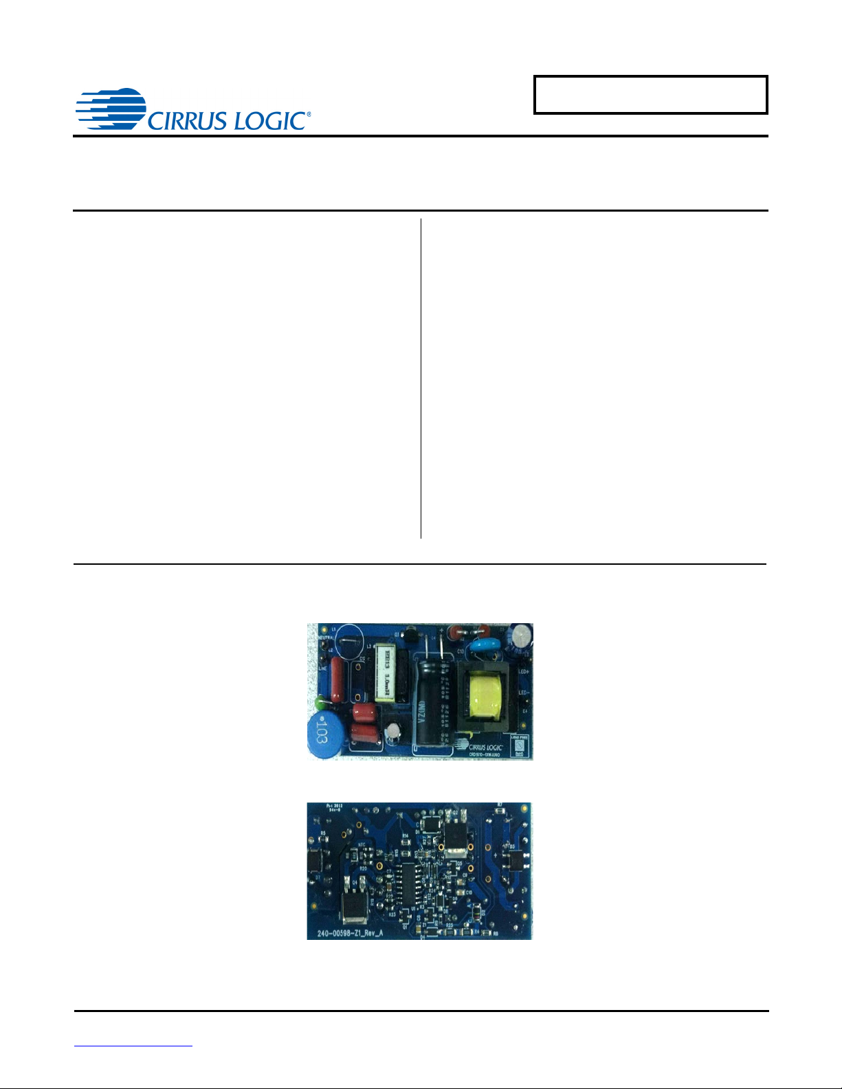
This application note provides an example of a Solid State
Lighting (SSL) LED lamp circuit designed using Cirrus
Logic’s CS1610, the CRD1610-15W-27V. The CRD161015W-27V reference design demonstrates the performance
of the CS1610 resonant mode AC/DC LED driver IC with a
470mA output driving
class dimmer compatibility and minimum dimming
performance with leading-edge, trailing-edge, and digital
dimmers. The form factor is targeted to fit into many LED
bulb applications (A19-type, PAR).
9xLEDs in series
. It offers best-in-
Cirrus Logic, Inc.
http://www.cirrus.com
Copyright Cirrus Logic, Inc. 2014
(All Rights Reserved)
AUG‘14
AN398
Page 2
AN398
Contacting Cirrus Logic Support
For all product questions and inquiries contact a Cirrus Logic Sales Representative. To find the one nearest to you
go to www.cirrus.com
IMPORTANT NOTICE
Cirrus Logic, Inc. and its subsidiaries ("Cirrus") believe that the information contained in this document is accurate and reliable. However, the information is subject
to change without notice and is provided "AS IS" without warranty of any kind (express or implied). Customers are advised to obtain the latest version of relevant
information to verify, before placing orders, that information being relied on is current and complete. All products are sold subject to the terms and conditions of sale
supplied at the time of order acknowledgment, including those pertaining to warranty, indemnification, and limitation of liability. No responsibility is assumed by Cirrus
for the use of this information, including use of this information as the basis for manufacture or sale of any items, or for infringement of patents or other rights of third
parties. This document is the property of Cirrus and by furnishing this information, Cirrus grants no license, express or implied under any patents, mask work rights,
copyrights, trademarks, trade secrets or other intellectual property rights. Cirrus owns the copyrights associated with the information contained herein and gives
consent for copies to be made of the information only for use within your organization with respect to Cirrus integrated circuits or other products of Cirrus. This consent does not extend to other copying such as copying for general distribution, advertising or promotional purposes, or for creating any work for resale.
CERTAIN APPLICATIONS USING SEMICONDUCTOR PRODUCTS MAY INVOLVE POTENTIAL RISKS OF DEATH, PERSONAL INJURY, OR SEVERE PROPERTY OR ENVIRONMENTAL DAMAGE ("CRITICAL APPLICATIONS"). CIRRUS PRODUCTS ARE NOT DESIGNED, AUTHORIZED OR WARRANTED FOR
USE IN PRODUCTS SURGICALLY IMPLANTED INTO THE BODY, AUTOMOTIVE SAFETY OR SECURITY DEVICES, LIFE SUPPORT PRODUCTS OR OTHER
CRITICAL APPLICATIONS. INCLUSION OF CIRRUS PRODUCTS IN SUCH APPLICATIONS IS UNDERSTOOD TO BE FULLY AT THE CUSTOMER'S RISK
AND CIRRUS DISCLAIMS AND MAKES NO WARRANTY, EXPRESS, STATUTORY OR IMPLIED, INCLUDING THE IMPLIED WARRANTIES OF MERCHANTABILITY AND FITNESS FOR PARTICULAR PURPOSE, WITH REGARD TO ANY CIRRUS PRODUCT THAT IS USED IN SUCH A MANNER. IF THE CUSTOMER
OR CUSTOMER'S CUSTOMER USES OR PERMITS THE USE OF CIRRUS PRODUCTS IN CRITICAL APPLICATIONS, CUSTOMER AGREES, BY SUCH USE,
TO FULLY INDEMNIFY CIRRUS, ITS OFFICERS, DIRECTORS, EMPLOYEES, DISTRIBUTORS AND OTHER AGENTS FROM ANY AND ALL LIABILITY, INCLUDING ATTORNEYS' FEES AND COSTS, THAT MAY RESULT FROM OR ARISE IN CONNECTION WITH THESE USES.
Cirrus Logic, Cirrus, the Cirrus Logic logo designs, EXL Core, and the EXL Core logo design are trademarks of Cirrus Logic, Inc. All other brand and product names
in this document may be trademarks or service marks of their respective owners.
IMPORTANT SAFETY INSTRUCTIONS
Read and follow all safety instructions prior to using this demonstration board.
This Engineering Evaluation Unit or Demonstration Board must only be used for assessing IC performance in a
laboratory setting. This product is not intended for any other use or incorporation into products for sale.
This product must only be used by qualified technicians or professionals who are trained in the safety procedures
associated with the use of demonstration boards.
Risk of Electric Shock
• The direct connection to the AC power line and the open and unprotected boards present a serious risk of electric
shock and can cause serious injury or death. Extreme caution needs to be exercised while handling this board.
• Avoid contact with the exposed conductor or terminals of components on the board. High voltage is present on
exposed conductor and it may be present on terminals of any components directly or indirectly connected to the AC
line.
• Dangerous voltages and/or currents may be internally generated and accessible at various points across the board.
• Charged capacitors store high voltage, even after the circuit has been disconnected from the AC line.
• Make sure that the power source is off before wiring any connection. Make sure that all connectors are well
connected before the power source is on.
• Follow all laboratory safety procedures established by your employer and relevant safety regulations and guidelines,
such as the ones listed under, OSHA General Industry Regulations - Subpart S and NFPA 70E.
Suitable eye protection must be worn when working with or around demonstration boards. Always
comply with your employer’s policies regarding the use of personal protective equipment.
All components and metallic parts may be extremely hot to touch when electrically active.
2
Page 3
AN398
1. INTRODUCTION
The CS1610 is a 120VAC quasi-resonant flyback mode dimmable LED controller IC. The CS1610 uses a digital control algorithm that is optimized for high efficiency and > 0.90 power factor over an input voltage range (108VAC to
132VAC). The CS1610 integrates a critical conduction mode (CRM) boost converter that provides power factor correction and dimmer compatibility with a constant output current, quasi-resonant flyback stage. An adaptive dimmer
compatibility algorithm controls the boost stage and dimmer compatibility operation mode to enable flicker-free operation from 0% to 100% output current with leading-edge, trailing-edge, and digital dimmers.
The CRD1610-15W-27V board is optimized to deliver low system cost in a high-efficiency, flicker-free, phasedimmable, solid-state lighting (SSL) solution for incandescent lamp replacement applications. The feedback loop is
closed through an integrated digital control system within the IC. Protection algorithms such as output open/short,
current-sense resistor open/ short, and overtemperature thermistors protect the system during abnormal conditions.
Details of these features are provided in the CS1610 data sheet.
The CRD1610-15W-27V board demonstrates the performance of the CS1610. This reference board has been designed for an output load of 9xLEDs in series at 470mA (
This data sheet provides the schematic and PCB layout for the reference design board. The performance graphs
demonstrate the performance of the CS1610 dimmable-controller reference design in terms of Efficiency vs. Line
Voltage, Power Factor vs. Line Voltage, THD vs. Line Voltage, Output Current vs. Line Voltage, and Output Current
vs. Dim Angle.
27.0V typical).
Extreme caution needs to be exercised while handling this board. This board is to be used by trained professionals
only.
3
Page 4
4
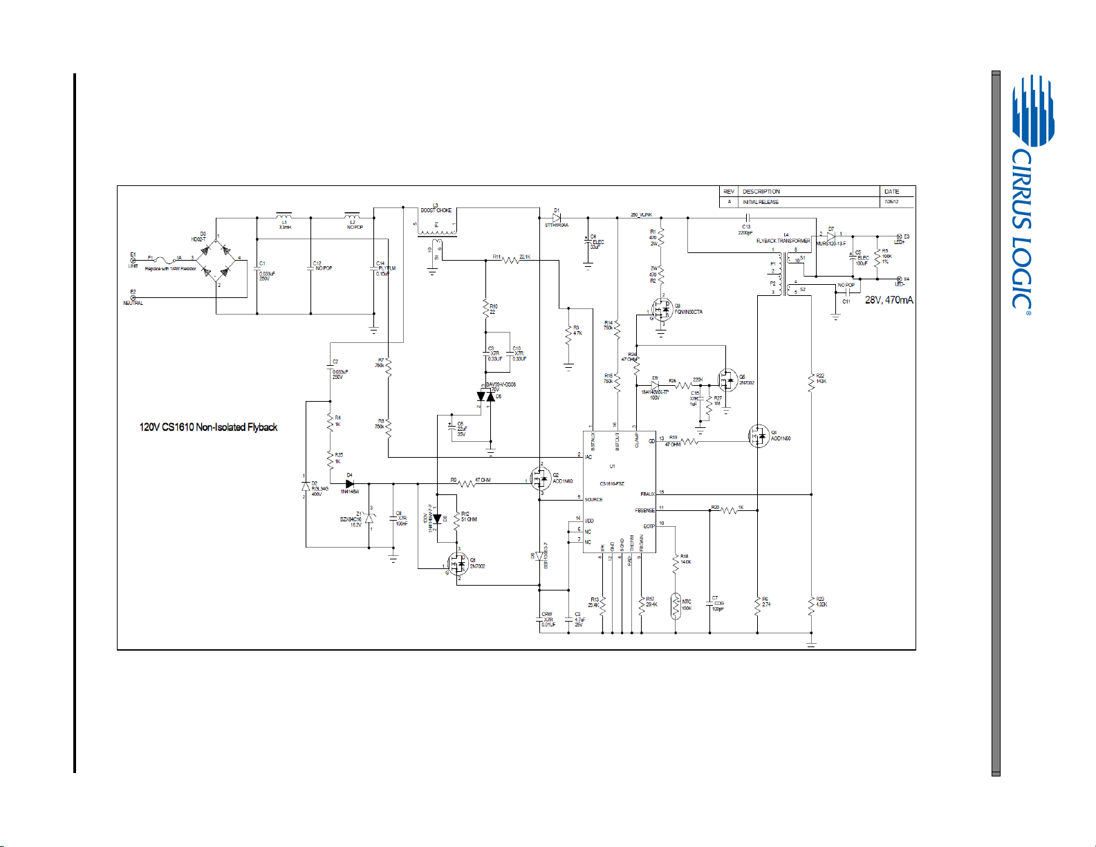
2. SCHEMATIC
Figure 1. Schematic
AN398
Page 5
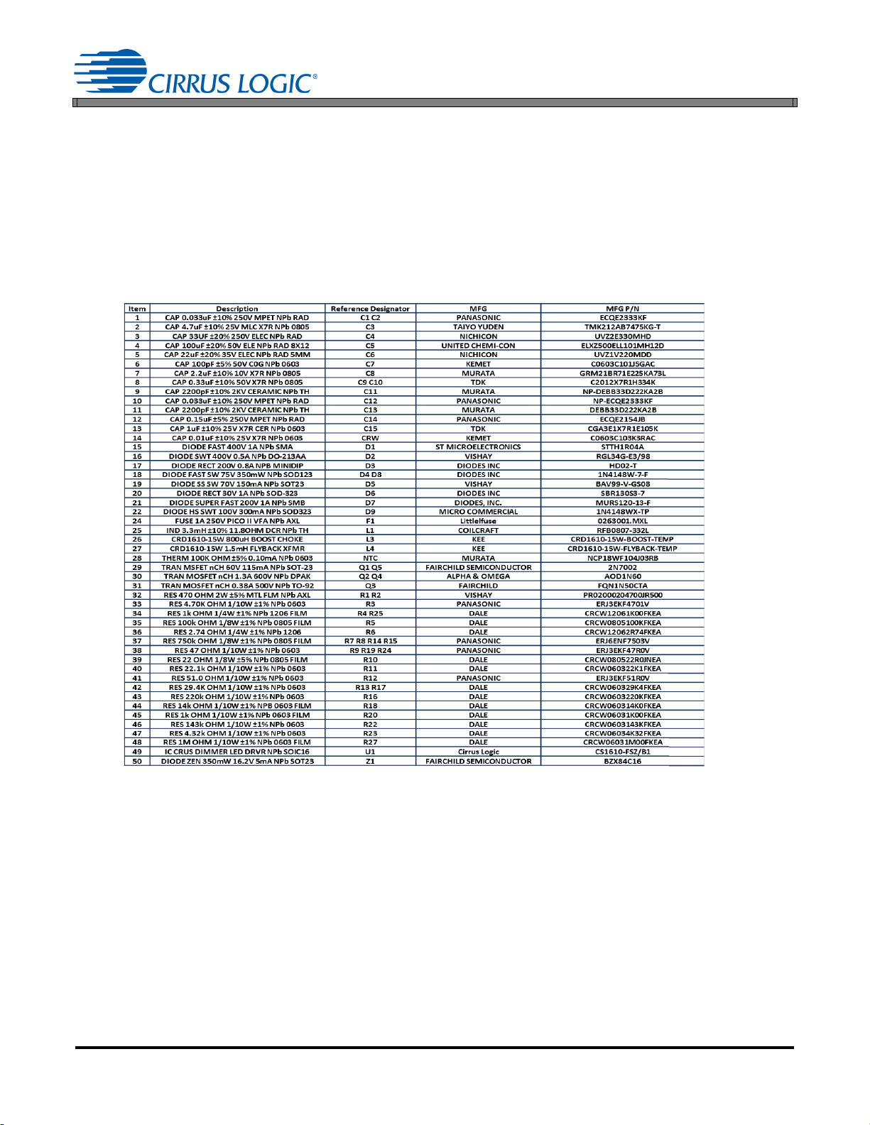
3. BILL OF MATERIALS
Table 1: Bill of Materials
AN398
5
Page 6

6
4. BOARD LAYOUT
Figure 2. Top Silkscreen
AN398
Page 7

AN398
7
Figure 3. Bottom Silkscreen
Page 8

8
Figure 4. Top Routing
AN398
Page 9

AN398
9
Figure 5. Bottom Routing
Page 10

5. THERMAL IMAGING
Figure 6. Top Thermal
Figure 7. Bottom Thermal
AN398
10
Page 11
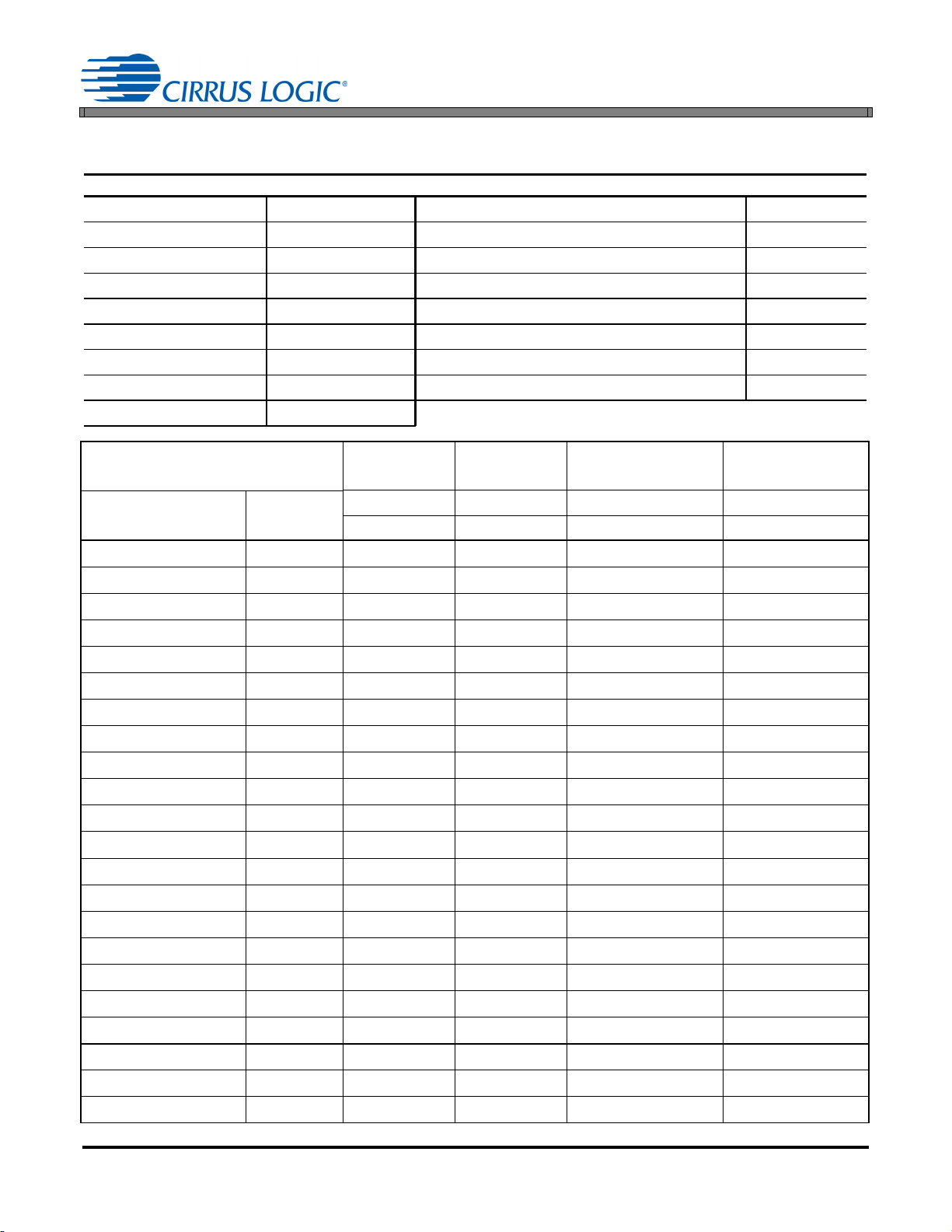
6. DIMMER COMPATIBILITY
A19 Lamp with a CS1615A (120V/ 60 Hz)
Date 9/10/2012 Power Factor
Vendor Cirrus Logic EN55015 Compliant (Y/N)
Input Voltage 120V/60Hz Nominal Input Power (W)
Form Factor N/A Maximum Input Power (W)
Model # CRD1610-15WA Output Voltage (V)
IC CS1610 Output Current (mA)
Topology Flyback Output Current Ripple 120Hz (mA)
Isolation (Y/ N) Y Output Power (W)
Efficiency (%)
80.6
1,4
1,4
1,4
1,2
1,2
1,4
1,3
AN398
0.934
N
16
16
28.068
460
50
12.91
Dimmer
Manufacture Type
Cooper 6001
Cooper 9530
GE 52136
Leviton 6161
Leviton 6613
Leviton 6615
Leviton 6627
Leviton 6631
Leviton 6641
Leviton 6683
Leviton 6684
Leviton 700
Leviton ACE04
Leviton ACM06
Leviton ACX10
Leviton HCM06
Leviton IPI06-1L
Leviton VZM06
Lutron AB-600M
Lutron DV-600P
Lutron DVCL-153P
Lutron DVELV-300P
5
Leading Edge
Leading Edge
Leading Edge
Leading Edge
Leading Edge
Trailing Edge
Leading Edge
Leading Edge
Leading Edge
Leading Edge
Leading Edge
Leading Edge
Trailing Edge
Leading Edge
Leading Edge
Leading Edge
Leading Edge
Leading Edge
Leading Edge
Leading Edge
Leading Edge
Trailing Edge
Flicker Free
Steady-State
Monotonic
Dimming
Max I
(mA) Min I
out
out
(mA)
# of lamps # of lamps # of lamps # of lamps
1 5 10 1 5 10 1 5 10 1 5 10
YYYYYY457457457 10 10 10
Y N N Y Y Y 462 459 457 11 10 10
YYYYYY459458457 11 10 10
YYYYYY460458457 11 10 10
YYYYYY459458458 10 10 10
YYYYYY456456456 12 10 10
YYYYYY460458458 45 41 38
YYYYYY457458457 10 10 10
YYYYYY457457457 10 10 10
YYYYYY459458458 10 10 10
YYYYYY461459458 10 10 10
YYYYYY459458458 10 10 10
YYYYYY455457457 10 10 10
YYYYYY459457458 10 10 10
YYYYYY455457457 39 38 38
YYYYYN457457457 10 10 10
YYYYYY459 458458 11 10 10
YYYYYY460 458457 11 10 10
YYYYYY457 457458 10 10 10
YYYYYY459 457458 11 10 10
YYYYYY457 457457 10 10 10
YYYYYY456 456456 10 10 10
11
Page 12

AN398
Dimmer
Manufacture Type
Lutron GL-600P
Lutron MAW-600
Lutron MIR-600
Lutron NT-2000
Lutron NTELV-600
Lutron NTLV-600
Lutron S-103P
Lutron S-600P
Lutron SELV-303P
Lutron SLV-600P
Lutron SLV-603P
Lutron SPS-600
Lutron SPSLV-1000
Lutron Tg-600P
Smarthome 2486D
1. Tested at nominal input voltage, nominal input frequency and without a dimmer after soaking for 15 minutes
2. Average
3. Peak-to-peak
4. Measured with Chroma 66202 Power Analyzer
5. This document includes trademarks, trade names, brands, logos, product names and/or product identifiers of companies other
than Cirrus Logic, Inc. All such trademarks, trade names, brands, logos, product names, and product identifiers are for
identification purposes only and are the property of their respective owners, who are not affiliated with Cirrus Logic. Please visit
the respective sites of those owners to obtain a listing or understanding of their trademark rights. This document also includes
results from testing performed by Cirrus Logic for its own purposes and for which there are currently no industry standards. While
this testing was applied objectively, its results may include at least some degree of subjectivity. The testing or test results should
not be interpreted as any comment on the overall quality or suitability of any tested products
5
Leading Edge
Leading Edge
Leading Edge
Leading Edge
Trailing Edge
Leading Edge
Leading Edge
Leading Edge
Trailing Edge
Leading Edge
Leading Edge
Leading Edge
Leading Edge
Leading Edge
Leading Edge
Flicker Free
Steady-State
Monotonic
Dimming
Max I
(mA) Min I
out
out
(mA)
# of lamps # of lamps # of lamps # of lamps
1 5 10 1 5 10 1 5 10 1 5 10
YYYYYY457 457457 10 10 10
YYYYYY456 457458 10 10 10
YYYYYY457 456458 10 10 10
YYYYYY457 457457 10 10 10
YYYYYY456 456456 10 10 10
YYYYYY459 457457 10 10 10
YYNYYY460457457 10 10 10
YYYYYY460 458457 11 10 10
YYNYYY455457457 10 10 10
YYYYYY460 457457 11 10 10
YYYYYY457 458458 10 10 10
YYYYYY457 457457 10 10 10
YYYYYY457 457457 10 10 10
YYYYYY457 457457 10 10 10
YYYYYY457 458457 10 10 10
12
Page 13

6. PERFORMANCE PLOTS
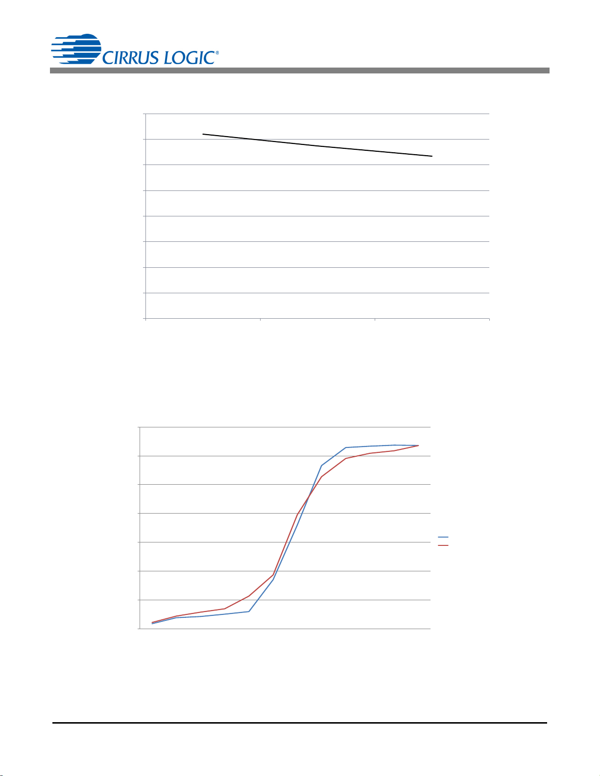
0.4
0.41
0.42
0.43
0.44
0.45
0.46
0.47
0.48
0.49
0.5
108 120 132
Output Current (A)
Line Voltage (V)
Figure 8. Output Current vs. Line Voltage
75%
80%
85%
90%
95%
100%
108 120 132
Efficiency (%)
Line Voltage (V)
Figure 9. Typical Efficiency vs. Line Voltage
AN398
13
Page 14
AN398
Figure 10. Power Factor vs. Line Voltage
0.6
0.65
0.7
0.75
0.8
0.85
0.9
0.95
1
108 120 132
Power Factor
Line Voltage (V
)
Figure 11. Input Power vs Dim Angle
0
2
4
6
8
10
12
14
15 30 45 60 75 90 105 120 135 150 165 180
Real Power
Dim Angle
Leading - 120 - 60
Trailing - 120 - 60
14
Page 15

7. REVISION HISTORY
Revision Date Changes
RD1 AUG 2014 Preliminary release
AN398
15
 Loading...