

Page 1
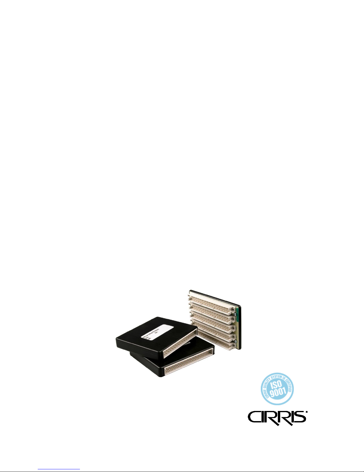
CH2
Performance Verification Manual
For the CH2 using
easy-wire software version 2009 or higher
Version 2014
June 10, 2014
An ISO 9001 Certified Company
Page 2

CH2 Performance Verification Manual
Version 2014.1.0
June 10, 2014
Copyright by Cirris System Corporation
1991 Parkway Boulevard
Salt Lake City, Utah 84119-2026
U.S.A
www.cirris.com
All Rights Reserved
Page 3

Performance
Verification
Introduction
The CH2 Performance Verification Kit allows you to verify calibration and proper operation of
the Cirris CH2 tester. Each CH2 Performance Verification Kit has a calibration date of five
years from the time of purchase. At the end of five years, the kit should be replaced or
recalibrated. Each component of this performance verification kit is tested with instruments
traceable to the NIST.
At least once a year, use the performance verification kit to verify the calibration of the CH2.
Also, use the kit whenever you suspect a problem with the CH2.
Note: There are no adjustments made to the CH2 tester during the performance verification
process. If the CH2 fails any step in the performance verification procedure, the tester must be
sent back to Cirris for repair.
For helpful information on setting up a calibration system to meet national calibration standards
such as ANSI/NCSL Z540-1, and ISO 10012-1, see Setting up a Calibration System in the
appendix of this manual.
This calibration procedure requires easy-wire software version 8.6 or higher.
You Should Have Received:
Performance
Verification
This
Document
Calibration
Documents
CH2 Low Voltage
Test Adapter
CH2 High Voltage
Test Adapter
CH2 Zero Ohm
Test Adapter
1
Page 4
Performance
Verification
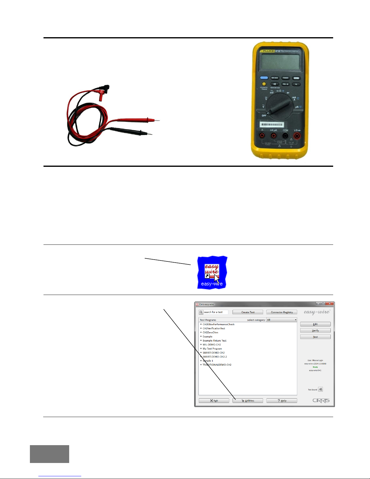
Required to Perform the Test:
Import/Configure the Test Files
Before performing the calibration procedure, you must import the test files to the station(s) or
network where the performance verification procedure is being performed. The following steps
will create a category called Calibration. Import the test files into the Calibration category, and
configure the test files to run.
To ensure you have the correct test files, re-import the files any time you update easy-wire or
anytime you haven’t run the test in a while. Re-importing test files guarantees they are the
correct version.
1. Start the easy-wire software.
2. From the Main Menu, click Utilities.
A multimeter capable of
measuring AC and DC
voltages. For both AC
and DC the meter needs
an input resistance of
10Mohm (+/-10%) and a
measurement accuracy
better than +/-1%.
(avoid using a bench top
meter)
Standard Pin Probe
Test Leads for a
multimeter.
2
Page 5
Performance
Verification
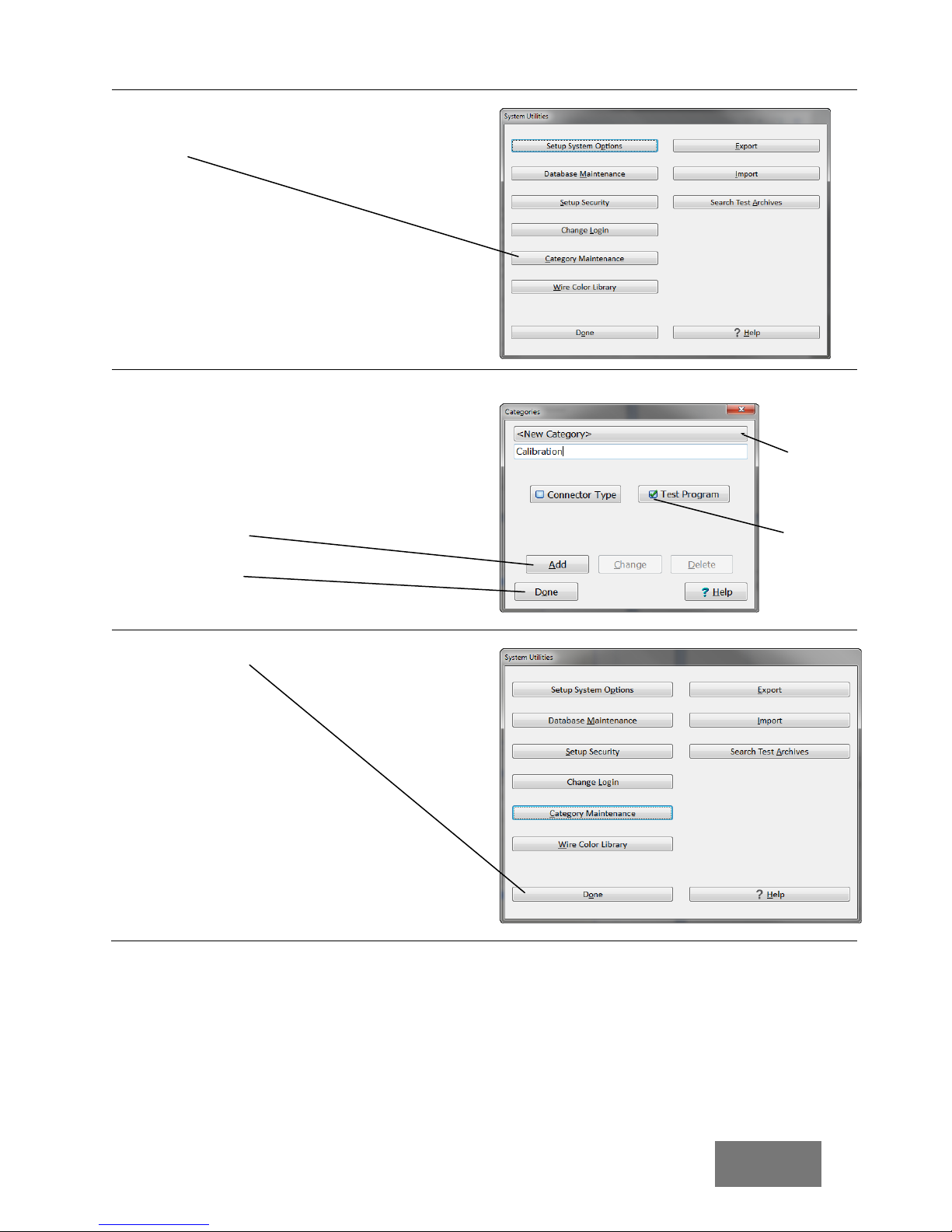
3. Click Test Category Maintenance (or Test
Category Maintenance in version 8.6).
4. Make sure Test Program is checked. Click
the down arrow and see if there is a
category called Calibration.
If there is no Category called Calibration,
create one by entering the word
“Calibration” in the text box and clicking
Add.
5. Click Done.
6. Click Done.
Make sure
Test
Program is
checked.
Click the
down arrow
to see the
available
categories.
3
Page 6
Performance
Verification
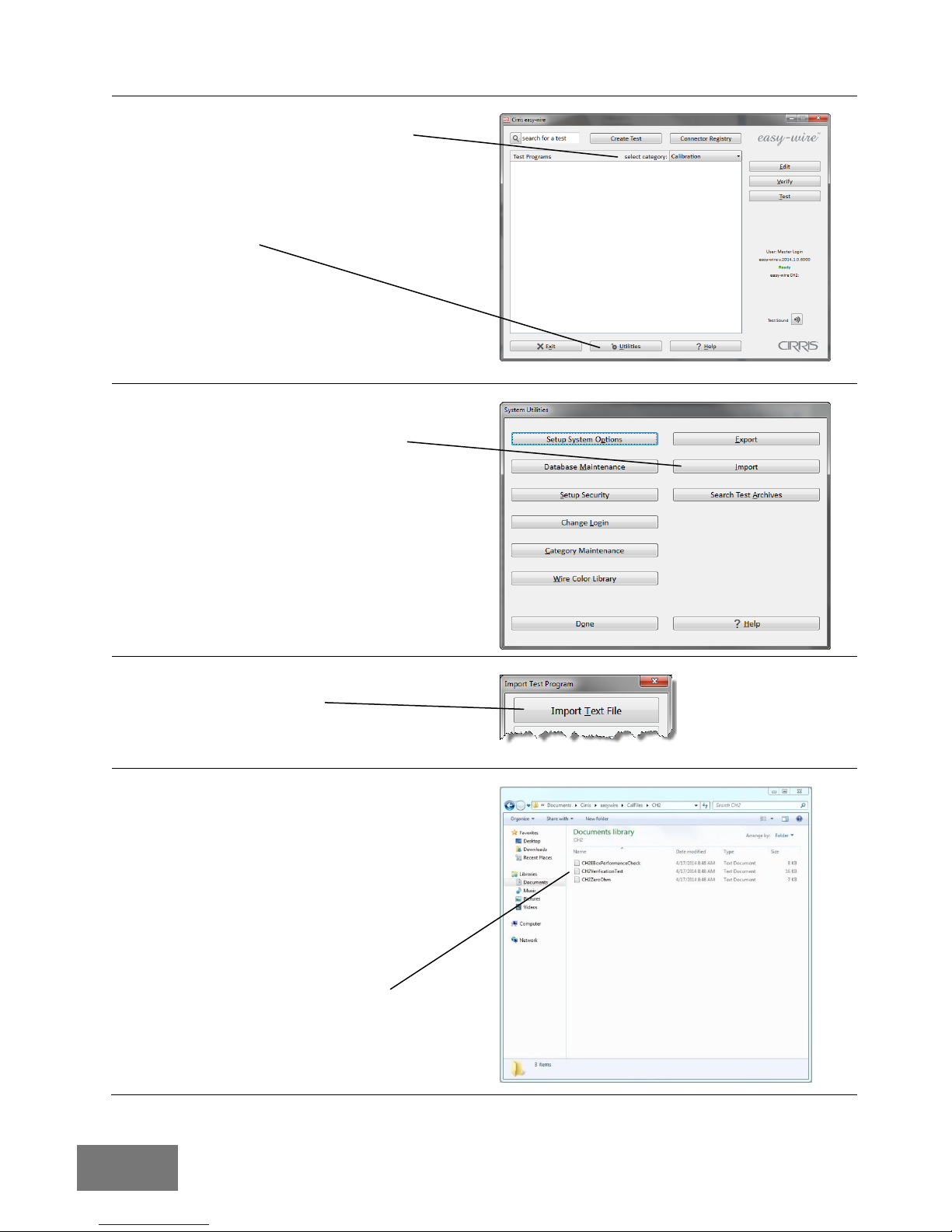
7. Select Calibration as the category.
8. Click Utilities.
9. In System Utilities, click Import.
10. Click Import Text File.
11. Browse to the path where the calibration
files are located.
c:\Documents and Settings\All
Users\Shared Documents\Cirris
\easywire\calfiles\CH2
Vista stores the files in:
c:\Users\Public\Public Documents\Cirris
\easywire\calfiles\CH2
12. Click CH2VerificationTest.txt,
and click Open.
4
Page 7
Performance
Verification
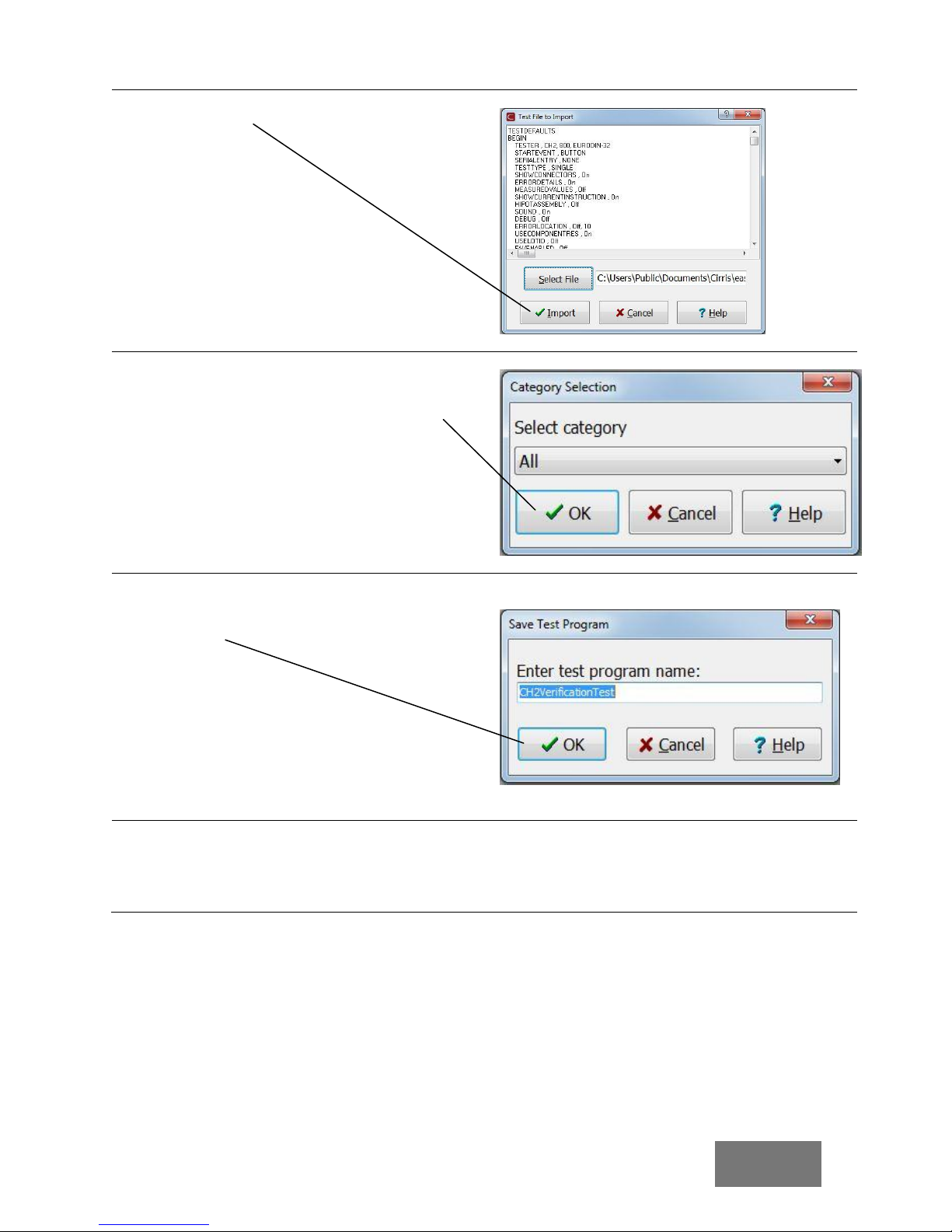
13. Click Import.
14. You may be asked to choose an existing
category for storing connector types. If so,
choose any category and click OK.
(This window will only appear the first time
calibration files are imported.)
15. When asked for a test program name, click
OK.
16. Follow the same process to import the test
file to test your CHE scanner modules.
Import: CH2ZeroOhm.txt
5
Page 8
Performance
Verification
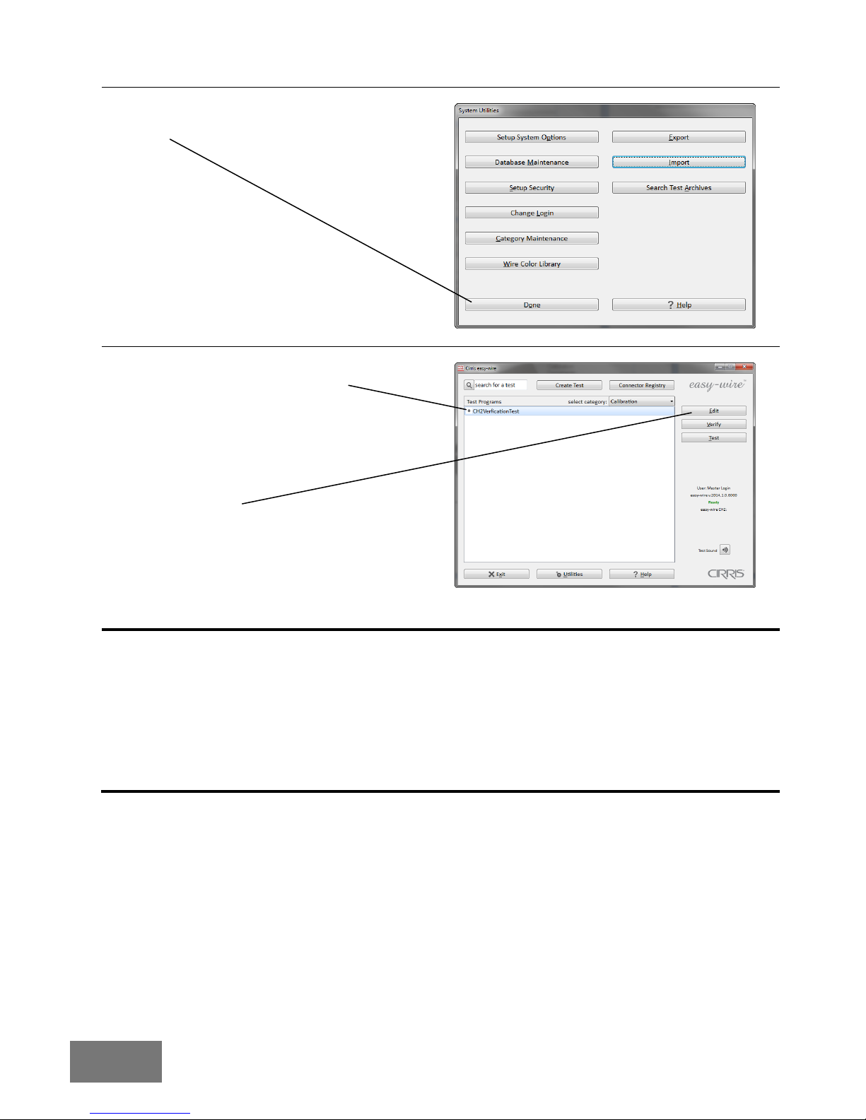
17. When you have imported all the files, click
Done to return to the main menu.
18. Select the CH2VerificationTest.
19. Click Edit.
Making Calibration Records
Your calibration system requirements may require you to prepare forms to record the
performance verification tests. At the end of the appendix you will find a CH2 Certificate of
Calibration and a CH2 Calibration Data Report. If using these forms, make a photocopy of
each one so you can maintain clean masters for the next time you perform the test procedure.
To fulfill more detailed test reporting requirements, you can use the test reporting capabilities of
the CH2 system. To setup this capability, see Creating Test Reports in the appendix.
6
Page 9
Test
Procedure
To verify the calibration of the CH2 analyzer, you will test the operation of the measurement
system as well as the operation of each of the 160 point scanner modules.
To test the measurement system:
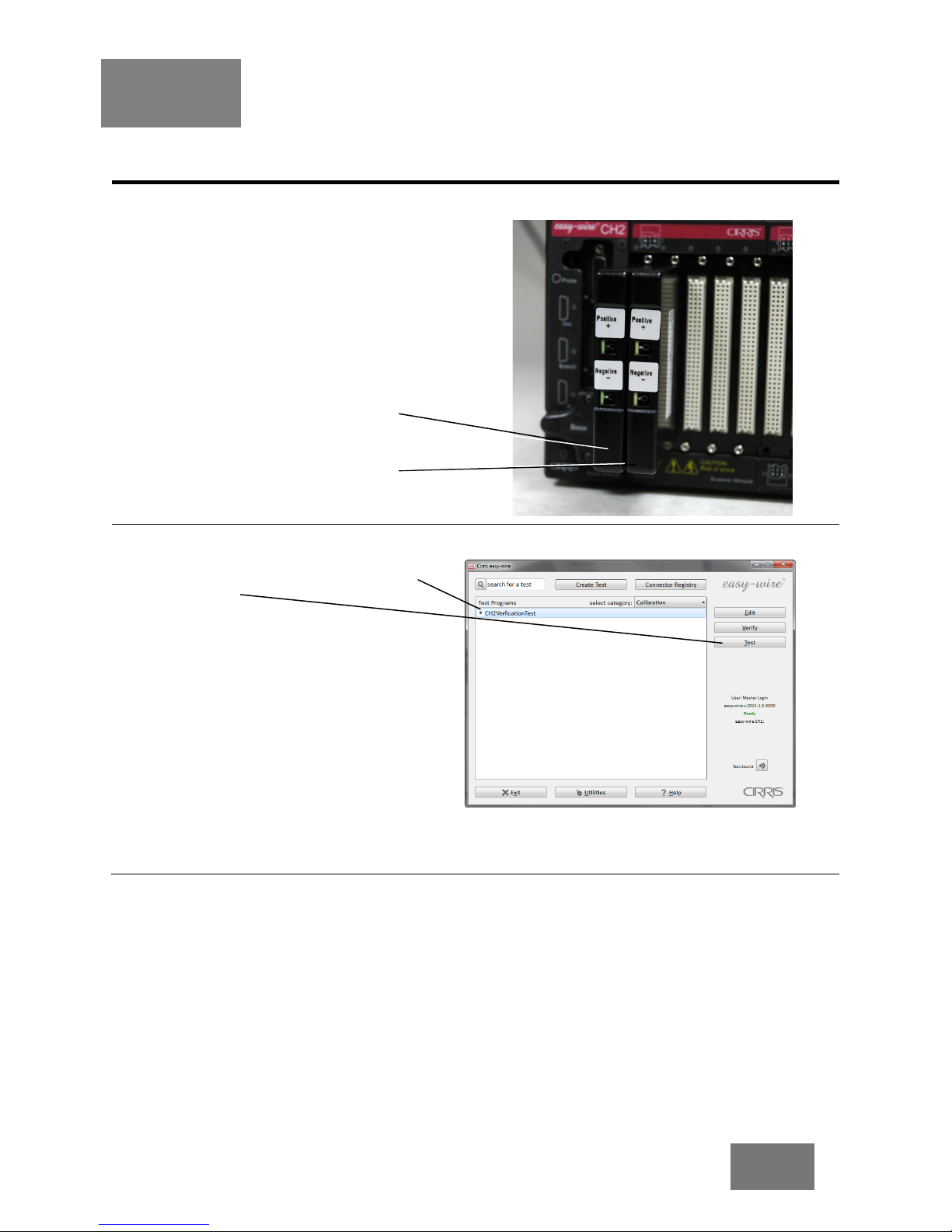
1. Install the CH2 Low Voltage Calibration
Adapter on the first connector of the
CH2 Test Point Scanner.
Install the CH2 High Voltage Calibration
Adapter on the second connector on the
CH2 Test Point Scanner.
2. From the Main Menu, click the test
program CH2VerificationTest and
click Test.
CH2 Low Voltage
Test Adapter
Test
Procedure
CH2 High Voltage
Test Adapter
7
Page 10
Test
Procedure
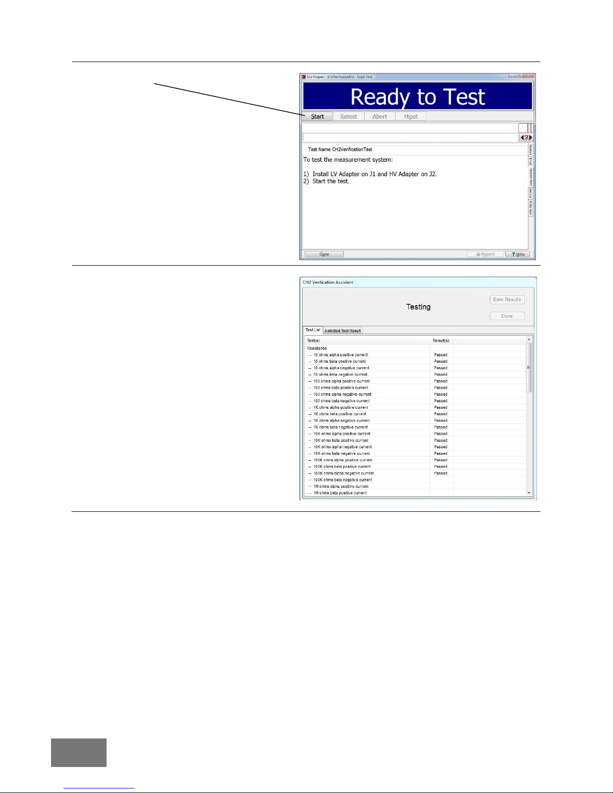
3. Click Start.
4. The CH2 Verification Assistant
window will open. Once the test starts,
this window will give you prompts to
complete the test.
8
Page 11
Test
Procedure
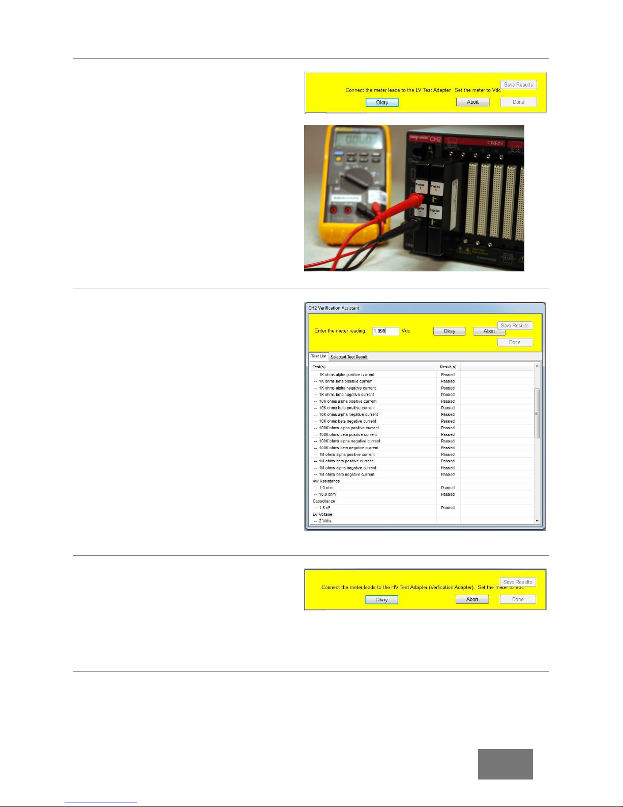
5. When the CH2 Verification Assistant
prompts you to attach the meter leads to
the CH2 Low Voltage Test Adapter,
insert the positive lead into the top jack
and the negative lead into the bottom
jack.
6. Set the meter to the range shown in the
prompt (“Vdc” for example).
Be ready to read the meter! Once you
click Okay, a voltage will appear on the
meter. The value will only be shown for
several seconds so be ready to read it.
7. Read the meter and enter the value (in
volts) into the box on the Verification
Assistant and click Okay.
Note: Some meters auto-scale the
measured results differently. The CH2 test
is written to accept values as volts. For
example, if the prompt is asking for an AC
Voltage Measurement and the meter
shows a value of 100 mV, the typed value
will be 0.100.
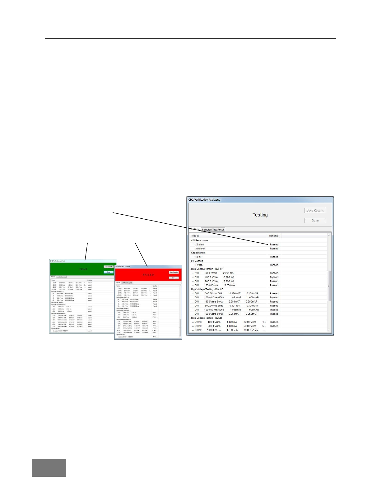
8. When the Verification Assistant prompts
you to attach the meter leads to the
CH2 High Voltage Test Adapter.
Move the positive lead into the top jack
and the negative lead into the bottom
jack of the HV Test Adapter.
9
Page 12
Test
Procedure
9. Each time you are prompted to read
the meter make sure you set the
meter to the range shown in the
prompt (“Vdc” or “Vac” for example).
Be ready to read the meter! Once you
click Okay, a voltage will appear on
the meter. The value will only be
shown for several seconds so you
need to be ready to read it.
10. When you are ready to read the meter,
click Okay.
11. Read the meter and enter the value (in
volts) into the box on the Verification
Assistant and click Okay.
Note: The HV Cal Adapter contains a voltage
divider circuit that reduces the high voltage down
to safe levels. This should work for any type of
meter and will be harmless if you come in contact
with the meter leads during the test.
Tests show their status as they are being
performed.
When complete, the test will show its final
status of PASSED or FAILED.
10
Page 13
Test
Procedure
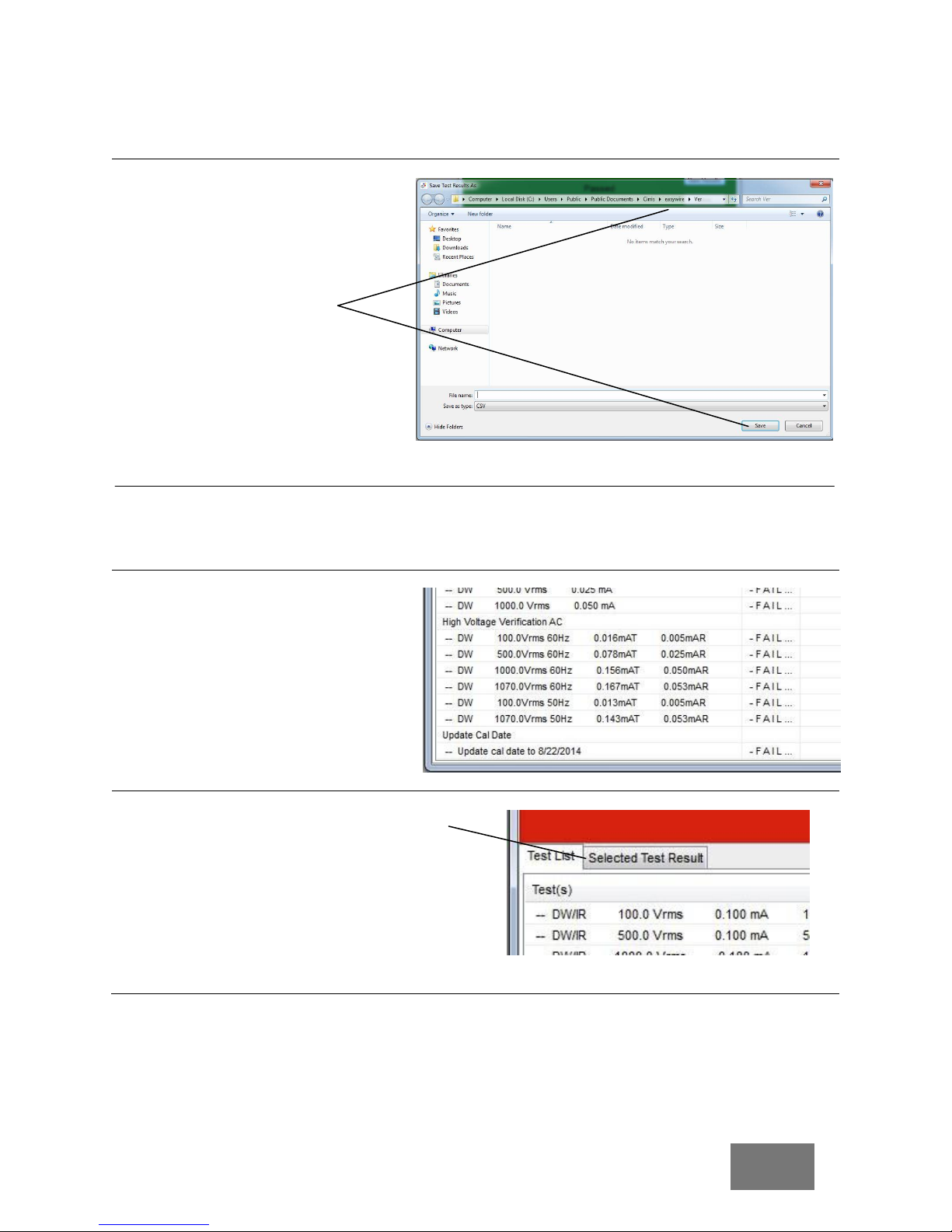
Once the test is complete, the
Verification Assistant will ask you
where you would like to save the test
results.
12. Choose a path and file
name for the test results.
13. Click Save.
The text file (.csv) that will be saved
can be loaded into any spreadsheet
program.
Note: There are no adjustments made to the CH2 tester during the performance verification
process. If the CH2 fails any step in the performance verification procedure, the tester must
be sent back to Cirris for repair.
Test results can be viewed for each
individual test by selecting the test you
want to view:
and clicking the Selected Test Result tab.
11
Page 14
Test
Procedure
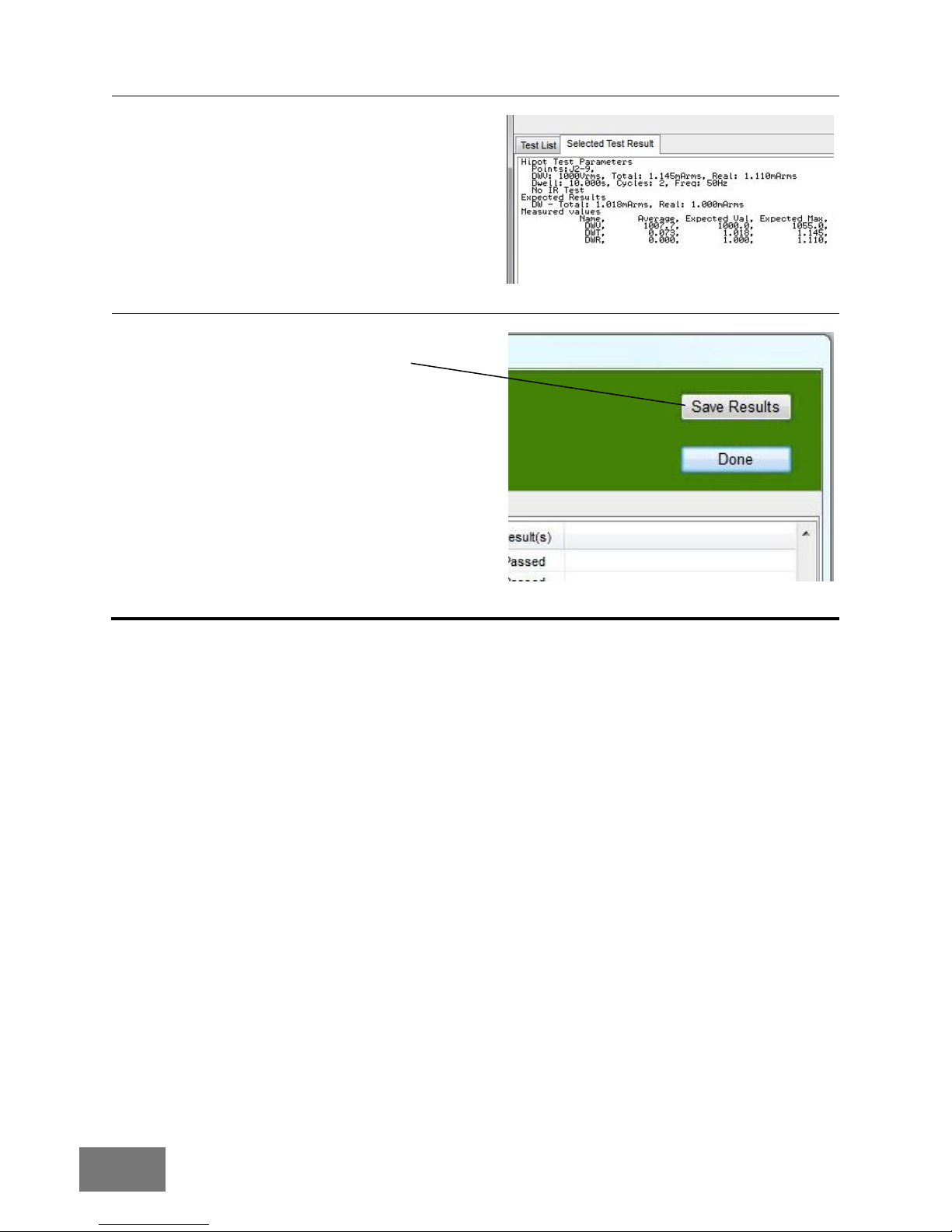
The details of the specific test as well as the
measured values will be displayed.
You can save additional copies of the test results
to a .csv file by clicking Save Results.
12
Page 15
Test
Procedure
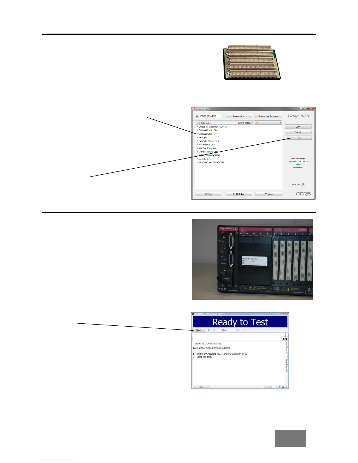
To test the scanner modules:
1. Remove the CH2 Low Voltage Test Adapter
and the CH2 High Voltage Test Adapter
from the CH2 analyzer.
2. Locate the CH2 Zero Ohm Cal Adapter.
3. From the Main Menu, select the
CH2ZeroOhm test from the list.
4. Click Test.
5. Attach the CH2 Zero Ohm Cal Adapter to
the first Scanner Module.
Note: The adapter is keyed to only fit one way
on the Scanner Module.
6. When the test shows Ready to Test, click
Start.
13
Page 16
Test
Procedure
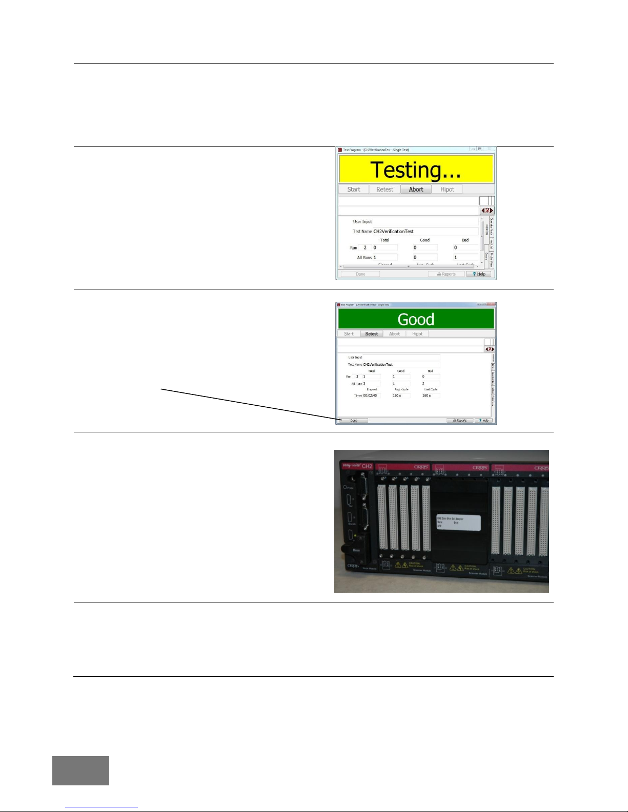
7. Press the zero ohm adapter firmly on
the front of the scanner module 1 and
press OK.
8. The test will run automatically.
9. The final status of the test will be displayed.
All of the module tests should pass.
The results can be marked on the Test Results
form at the end of these instructions.
10. Click Done.
11. Move the CH2 Zero Ohm Cal Adapter to the
corresponding scanner module, and press ok
to continue the tests, until all the Scanner
Modules have been tested.
.
Testing is now complete.
14
Page 17

Appendix
Setting Up a Calibration System
The information below is meant as an introduction to setting up a formal calibration system in
your organization.
Calibration Standards
Calibration standards refer to written quality system requirements for organizations that
perform calibrations and use calibrated equipment. Establishing a quality system according
to calibration standards helps ensure calibrations are done competently and lends credibility
to the calibration organization. In the United States, common calibration standards include
ANSI/NCSL Z540-1, ISO/IEC Guide 25, ISO 10012-1, and the former MIL-STD 45662A.
The ANSI/NCSL Z540 standard referred to above, as well as other helpful metrology
information, can be obtained from the National Conference of Standards Laboratories
International (NCSL) at 1-303-440-3339 or www.ncslinternational.org. You can obtain the
ISO standards from the International Standards Organization (ISO) at their web site
www.iso.net/.
Good Calibration Practices
The calibration standards, such as ANSI/NCSL Z540-1 and ISO 10012-1 require several
good practices for the calibration industry including the following areas:
Establish a recall system
How do you ensure that you don’t forget to send an instrument in for calibration? A recall
system can be a card file or a computerized database which includes calibration dates, due
dates, calibration sources, and other instrument records. The recall system ensures
calibrated instruments are recalibrated in a timely manner.
Calibration Labels
How does someone know if an instrument has been calibrated without looking for the
paperwork in a filing cabinet drawer? When an instrument is calibrated, the calibration
standards require the instrument to be labeled as such. The calibration labels, which are
applied to instruments, have fields for the instrument serial number, calibration date,
calibration due date, and by whom.
Test Accuracy Ratios
Wherever possible, calibration standards require an accuracy ratio of at least four to one. In
other words, the insturment being used to measure the calibrated instrument should be at
least four times as accurate as the calibrated instrument.
Certificate of Calibration
How does everyone know you had an instrument calibrated? The calibration certificate is the
record of who, when, and by what equipment the instrument was calibrated.
A CH2 Certificate of Calibration, which you can photocopy for your calibration, is provided
following this section.
Appendix
15
Page 18

Appendix
Calibration Data Report
So how accurate is the calibrated test instrument in relation to its published
specifications? Some organizations require the measured values of a calibrated instrument
are written down when an instrument is calibrated. Calibration laboratories typically charge
extra to create a calibration data report. However, when a calibrated instrument is found to
be out-of-tolerance, the calibration standards require the out-of- tolerance data be recorded
in relation to the instruments specifications. A calibration data report can fill this requirement.
A calibration data report, you can photocopy to use for your CH2 calibration, is provided
following this section.
Traceability
Did qualified personnel perform the calibration procedure under controlled conditions, using
correctly calibrated instruments with the correct test accuracy ratios? To maintain
traceability, the answer to all these questions must be yes. Traceability refers to each
unbroken link of valid calibrations going back to national standards such as those maintained
by the NIST in the United States.
Several years ago NIST numbers (ie. reference numbers issued on NIST reports) were
commonly copied on successive calibration certificates as a means of showing traceability.
This practice has been discontinued. Therefore, if you are writing a calibration procedure,
do not require NIST numbers be copied on reports to show traceability. NIST numbers are
sometimes confused with other numbers that calibration laboratories create for reference
such as “asset numbers”, “NIST trace numbers”, “ID numbers”, and “report numbers.” For
more information regarding the discontinued use of NIST numbers, Cirris can provide a copy
of the position paper from the National Conference of Standards Laboratories.
16
Page 19
Appendix
Creating Test Reports
The results of the performance verification are stored two of the following ways.
1. The CH2VerificationTest allows you to save a .csv file that contains the results of each
test performed on the measurement system of the CH2. The .csv file can be examined,
printed, and loaded into any spreadsheet program; it’s intended to be a key part of your
test results.
2. The results for all test runs (both the CH2VerificationTest and each of the
C_CalModule tests) are stored in the easy-wire database and are accessible from the
Test Archive Report or from the In Process Report, features of the easy-wire software.
Those reports save the summary of the testing that was done. If required, you can have
the CH2 save more information about the tests. To save more information for each test,
do the following steps:
Before running the test:
1. From the easy-wire Main Menu, click on the test program you wish to use to turn on
the test data storage options.
2. Click Edit.
3. At the top of the Test Program Editor screen, click the Set Test Defaults tab.
4. Check the Store measured test value box.
5. Check the Store High Voltage IR Values box (if the box is enabled).
6. Click Done at the bottom of the screen.
7. Select Yes, save changes and return to the main menu.
After the test program completes, while still in the test:
1. Click Reports at the bottom of the test program screen.
2. Click In Process Report and a test report will open.
3. Use the report’s Print Menu to print or create a .pdf of the report.
Customer Service
If you need any assistance with this performance verification, call Cirris customer service tollfree at 1-800-441-9910.
Cable/Harness testing made easy
17
Page 20
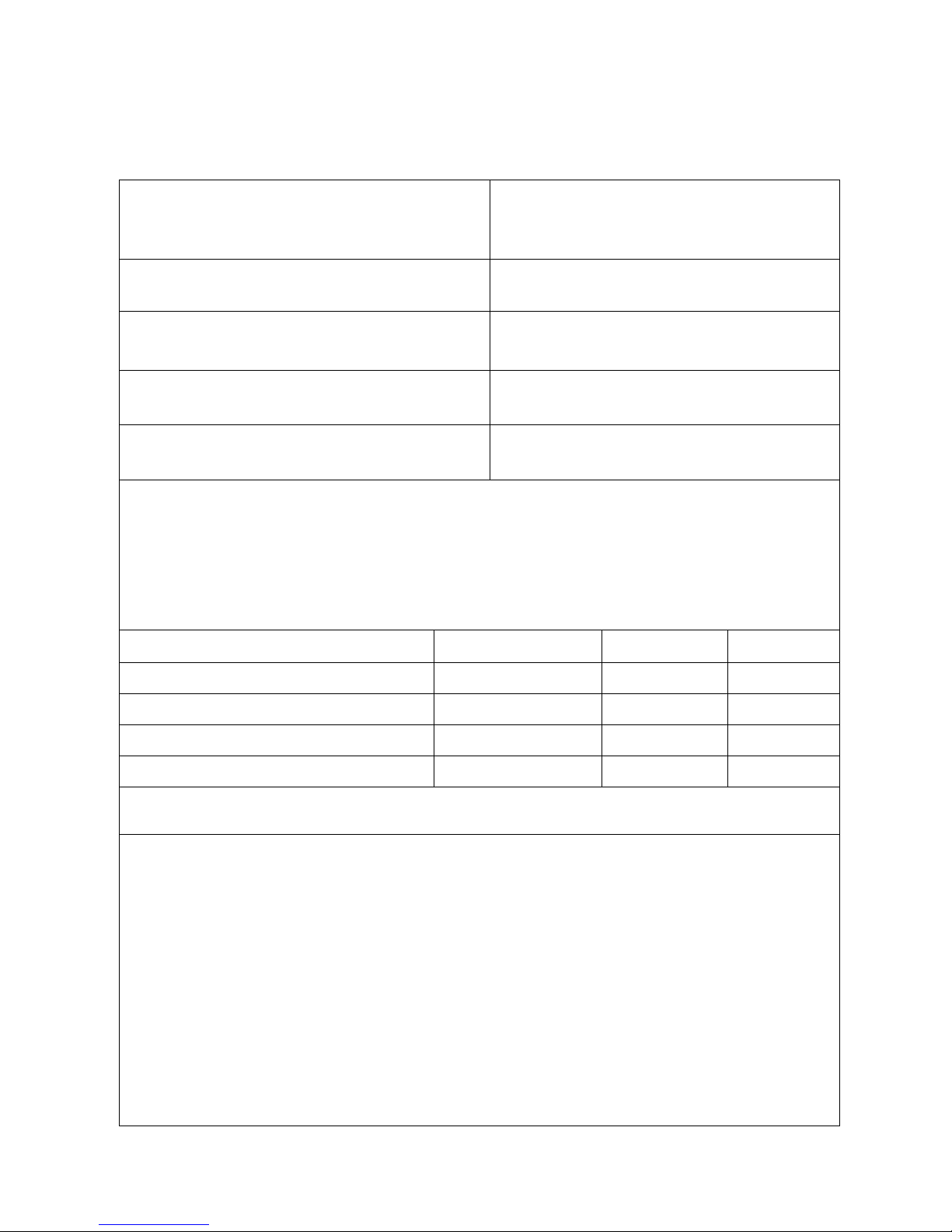
CH2 Certificate of Calibration
Organization performing the calibration:
Organization Address:
Certificate Number:
Calibrated by:
Calibrated:
Due:
Applicable Calibration Standard(s):
Procedure:
CH2 Performance Verification
Temperature:
Relative Humidity:
Serial Numbers:
Instruments used:
Serial Number
Cal Date
Due
CH2 Low Voltage Calibration Adapter
CH2 High Voltage Calibration Adapter
CH2 Zero Ohm Calibration Adapter
Multimeter
Statement of Traceablility:
Certified by:
Page 21
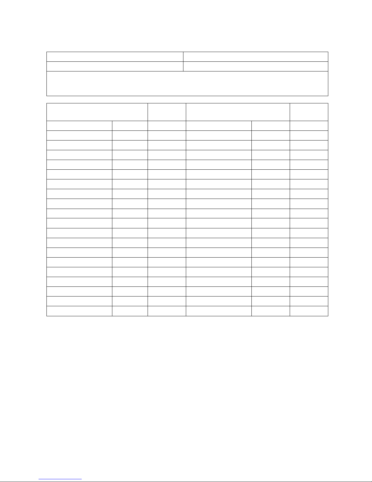
CH2 Calibration Data Report
Report Number:
Calibrated by:
Tester Serial Number:
Calibration date:
Test / Serial Number
Recorded
Value
Test / Serial Number
Recorded
Value
Scanner Module 1
Pass / Fail
Scanner Module 21
Pass / Fail
Scanner Module 2
Pass / Fail
Scanner Module 22
Pass / Fail
Scanner Module 3
Pass / Fail
Scanner Module 23
Pass / Fail
Scanner Module 4
Pass / Fail
Scanner Module 24
Pass / Fail
Scanner Module 5
Pass / Fail
Scanner Module 25
Pass / Fail
Scanner Module 6
Pass / Fail
Scanner Module 26
Pass / Fail
Scanner Module 7
Pass / Fail
Scanner Module 27
Pass / Fail
Scanner Module 8
Pass / Fail
Scanner Module 28
Pass / Fail
Scanner Module 9
Pass / Fail
Scanner Module 29
Pass / Fail
Scanner Module 10
Pass / Fail
Scanner Module 30
Pass / Fail
Scanner Module 11
Pass / Fail
Scanner Module 31
Pass / Fail
Scanner Module 12
Pass / Fail
Scanner Module 32
Pass / Fail
Scanner Module 13
Pass / Fail
Scanner Module 33
Pass / Fail
Scanner Module 14
Pass / Fail
Scanner Module 34
Pass / Fail
Scanner Module 15
Pass / Fail
Scanner Module 35
Pass / Fail
Scanner Module 16
Pass / Fail
Scanner Module 36
Pass / Fail
Scanner Module 17
Pass / Fail
Scanner Module 37
Pass / Fail
Scanner Module 18
Pass / Fail
Scanner Module 38
Pass / Fail
Scanner Module 19
Pass / Fail
Scanner Module 39
Pass / Fail
Scanner Module 20
Pass / Fail
Scanner Module 40
Pass / Fail
 Loading...