

Page 1
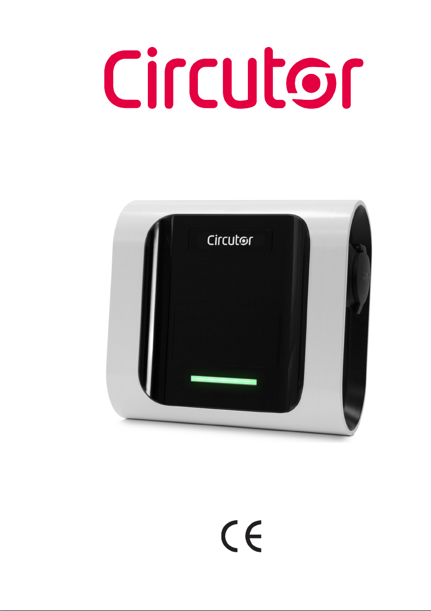
Wallbox eNext Series
INSTRUCTION MANUAL
(M255B01-03-19B)
Page 2
Wallbox eNext
Disclaimer
CIRCUTOR, SA reserves the right to make modifications to the device or the unit specifications set out in this instruction manual without prior notice.
CIRCUTOR, SA on its web site, supplies its customers with the latest versions of the device specifications and the most updated manuals.
www.circutor.com
Revision log
Date Revision Description
06/19 M255B01-03-19A Initial Version
Changes in the following sections:
11/19 M255B01-03-19B
2
1.- 2. - 3.A. - 3.C. - 4. - 5. - 6. - 7. - 8. - 9. - 10. - 11.
- 12.
Instruction manual
Page 3

Wallbox eNext
Wallbox eNext
Instruction Manual
COPYRIGHT INFORMATION
This document is copyrighted, 2019 by Circutor, S.A. All rights are reserved.
Circutor, S.A. reserves the right to make improvements to the products described in
this manual at any time without notice.
No part of this manual can be reproduced, copied, translated or transmitted
in any form or by any means without the prior written permission of the original
manufacturer. Information provided in this manual is intended to be accurate and
reliable. However, the original manufacturer assumes no responsibility for its use, or
for any infringements upon the rights of third parties athat may result from its use.
All other product names or trademarks are properties of their respective owners.
Instruction manual
3
Page 4

Wallbox eNext
4
Instruction manual
Page 5

Wallbox eNext
Here’s your
guide to use and
configure eNext.
Disclaimer ....................................................................................................................................................2
Revision log...................................................................................................................................................2
Here’s your guide to use and configure eNext....................................................................................5
1.-So,hello!....................................................................................................................................................8
2.-Features.................................................................................................................................................10
3.- First steps............................................................................................................................................12
A. Download “HiCharger” App.......................................................................................................12
B. QRSCAN...........................................................................................................................................14
C. MANUAL...........................................................................................................................................14
4.- How to use it? - Plug&Charge.........................................................................................................16
A. Standby............................................................................................................................................16
B. Start charging................................................................................................................................16
C. Charging...........................................................................................................................................16
D. Charge stopped..............................................................................................................................16
E. EV fully charged.............................................................................................................................17
F. Stop charging..................................................................................................................................17
5.- How to use it? - Presence recognition.........................................................................................18
A. Standby............................................................................................................................................18
B. User identification.........................................................................................................................19
C. Start charging.................................................................................................................................19
D. Charging................................................... ......................................................................................20
E. Charge stopped....................................... ......................................................................................20
F. EV fully charged.............................................................................................................................20
F. Stop charging..................................................................................................................................21
6.- “HiCharger” App - List.......................................................................................................................22
A. Overview..........................................................................................................................................22
B. Status...............................................................................................................................................23
Instruction manual
5
Page 6

Wallbox eNext
7.- “HiCharger” App -Dashboard..........................................................................................................24
A. Overview..........................................................................................................................................24
B. Status...............................................................................................................................................25
C. Error information..........................................................................................................................26
D. Management options.....................................................................................................................27
8.- “HiCharger” App -Charger Options................................................................................................28
A. Overview..........................................................................................................................................28
B. Identification method....................................................................................................................29
C. Time schedule.................................................................................................................................29
D. Diagnostic........................................................................................................................................30
E. Firmware.........................................................................................................................................32
F. Advanced settings.........................................................................................................................33
9.- “HiCharger” App -Settings................................................................................................................36
A. Overview..........................................................................................................................................36
B. About.................................................................................................................................................37
C. General.............................................................................................................................................38
10.- Factory reset.......................................................................................................................................40
11.- LED beacon notifications - Legend..............................................................................................42
A. Blinking red errors........................................................................................................................44
B. Blinking yellow status..................................................................................................................45
12.- Technical Data...................................................................................................................................46
Need help?..................................................................................................................................................49
Guarantee....................................................................................................................................................49
6
Instruction manual
Page 7

Wallbox eNext
Instruction manual
7
Page 8
Wallbox eNext
1
This manual provides information about the usability and configuration of the
Wallbox eNext, which has been designed and tested to allow electric vehicle
charging, specified in IEC 61851.
It contains all the necessary information for safe use and help to get the best
performance from it with step-by-step configuration instructions.
THE FOLLOWING SYMBOLS ARE USED FOR IMPORTANT
SAFETY INFORMATION IN THIS DOCUMENT
ATTENTION!
Indicates that damage to property can occur if appropriate
precautions are not taken.
• Complies with IEC 61851-1, Electric vehicle conductive charging
system (IES 61851-1:2017)
• Complies with IEC 62196, Plugs, socket-outlets, vehicle couplers
and vehicle inlets (IEC 62196-1 and IEC 62196-2).
• Standards: 2014/35/UE, LVD;2014/30/UE, EMC.
8
Instruction manual
Page 9
Wallbox eNext
So, hello!
IMPORTANT SAFETY INFORMATION
Read carefully all the instructions before manipulating
the unit.
The Charge Point may not include elements of electrical protection.
• Read all the instructions before
using and configurating this
product.
• Do not use this unit for anything
other than electric vehicle
charging.
• Do not modify this unit. If
modified, CIRCUTOR will reject
all responsibility and the warranty
will be void.
• Comply strictly with electrical
safety regulations according to
your country.
• Do not make repairs or
manipulations with the unit
energised.
• Use only CIRCUTOR supplied
spare parts.
• Only trained and qualified
personnel should have access to
electrical parts inside the device.
• Check the installation annually by a
qualified technician.
• Remove from service any item that
has a fault that could be dangerous
for users (broken plugs, caps that
don’t close...).
• Do not use this product if the
enclosure or the EV connector is
broken, cracked, open, or shows
any other indication of damage.
• Do not use any adapter, except
those approved by the EV
manufacturer
Instruction manual
9
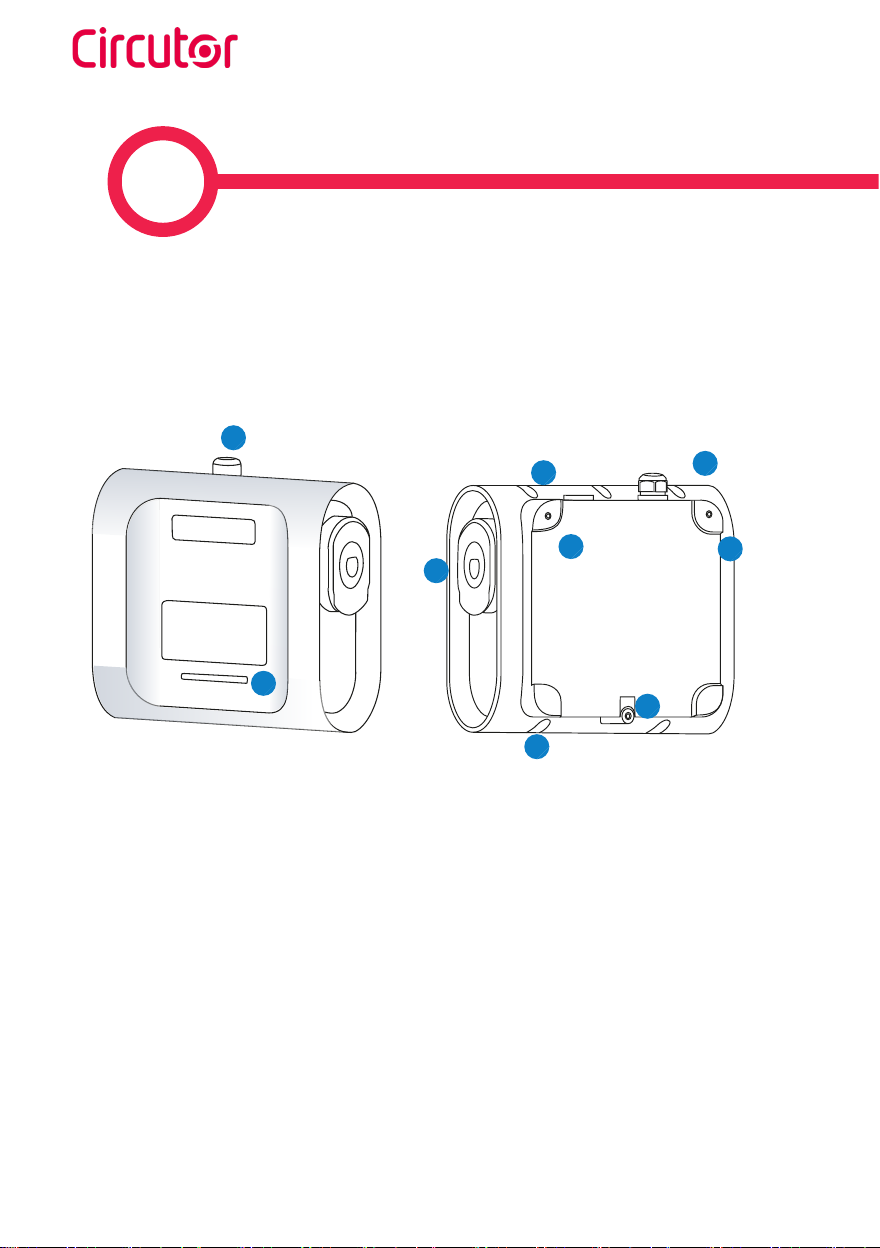
Page 10
2
Wallbox eNext
2
5
2
1 — LED beacon light
2 — Cable glands
1
3 — Plugs
4 — Wall support holes
4
4
3
4
5
(1)
(1)
Plugs may vary depending on the model
5 — Closing box holes
10
Instruction manual
Page 11

Wallbox eNext
Features
MAIN FEATURES OF THE UNIT
Charge Point may not include elements of electrical protection.
• ABS plastic housing: Robust
Plastic material to resist severe
environmental conditions including UV
rays and mechanical stress
• Connector Lock: Type 2 connector has
a lock system to avoid an EV unduly
disconnection.
• LED Beacon Light: Colour LED system
that indicates the status of the Charge
Point.
• Bluetooth: Bluetooth v4.2 + BLE
wireless communications for remote
charge activation and charge point
configuration
• App: Easy software interface to set
up the language configuration, user
authentification, Wallbox diagnosis and
firmware upgrades, among others.
Instruction manual
11
Page 12
3
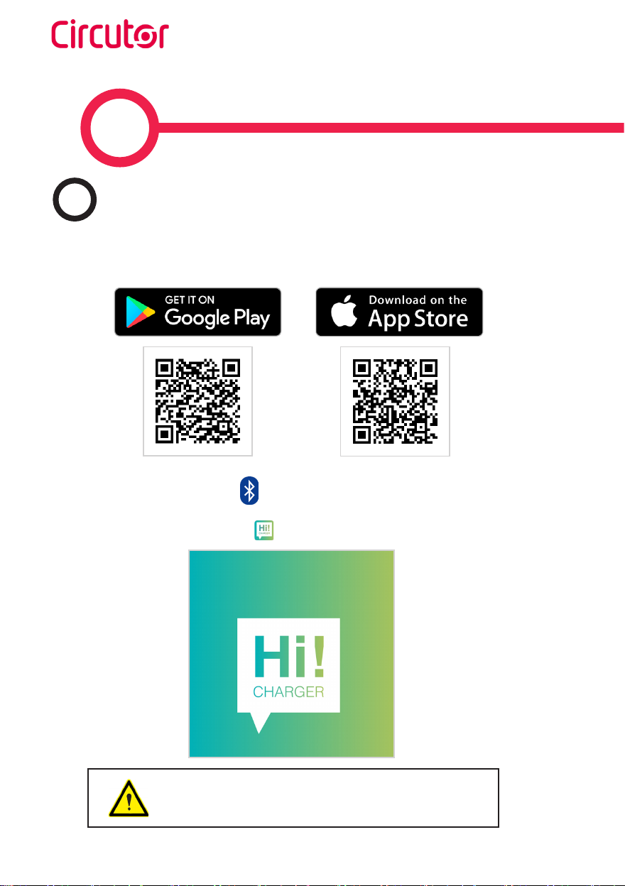
Download “HiCharger” App
A
1. Download the app ‘HiCharger’,
Wallbox eNext
2. Enable smartphone bluetooth.
3. Open the mobile app ‘HiCharger’.
Compatible with Android version 4.4.2 or latest and IOS
version 9 or latest
12
Instruction manual
Page 13
Wallbox eNext
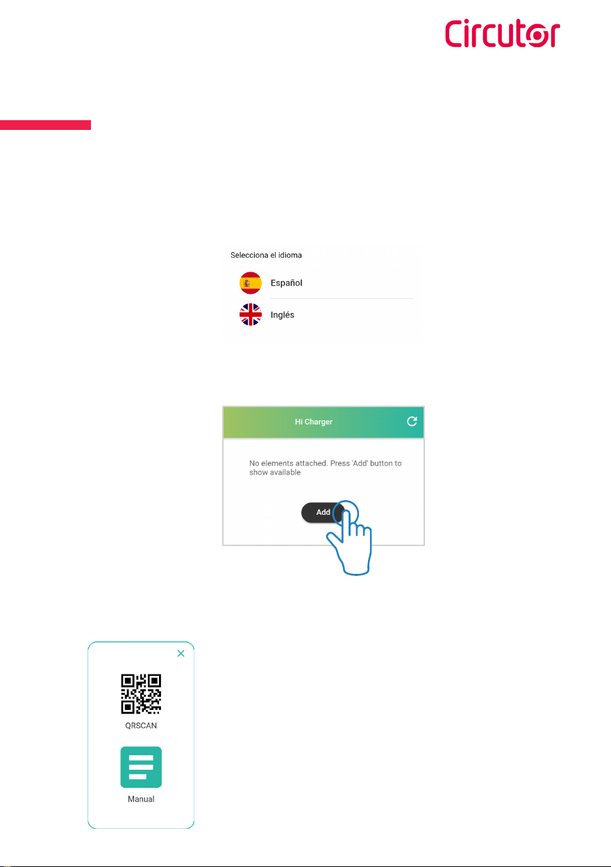
First steps
4. Select your language
5. Tap the “Add” button in order to pair a new Charge Point.
6. Select the mode.
Instruction manual
• QRSCAN: This option allows to perform the pairing
automatically, by only scanning the QR code. For further
information please refer to section B.- QRSCAN of this
chapter.
• MANUAL: This option allows to perform the pairing
by choosing manually the Charge Point from a list and
entering its password. For further information please
refer to section “C - MANUAL” of this chapter.
13
Page 14

B
QRSCAN
Scan the QR code provided.
There are two identification labels containing
the same unique QR code for each charge
point. One of them is attached to the
installation manual and the other one is
patched inside the charge point as shown:
Wallbox eNext
C
801F12B2XXXX;2;YYYY
MAC: 80:1F:12:B2:XX:XX
PASSWORD: YYYY
Push to refresh the devices detected
throught the smartphone’s bluetooth.
14
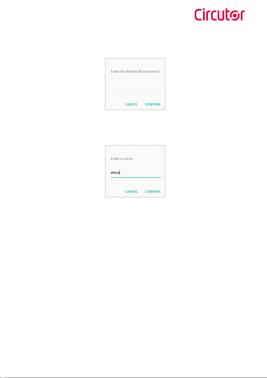
MANUAL
Select the charge point and introduce the password.
The MAC to identify the charge point and the password
can be found on the two identification labels as shown
in the picture beside. One of them is attached to the
installation manual and the other one is patched
inside the charge point.
Instruction manual
Page 15
Wallbox eNext
The password is required after selecting the charge point.
7. The charger point name can be customized.
8. Once the charge point is paired, its connectivity status is visible on the ‘List’ screen.
From now on, the charge point can be managed following the instructions of this manual.
Instruction manual
15
Page 16

Wallbox eNext
4
Plug&Charge identification method is set by factory default and enables the user to start
a charging transaction without an identification. This configuration could be adequate for
equipment placed in private areas where only reliable users have access.
A
When the Charge Point LED beacon light is green in a fade-in/
fade-out eect, it means that the unit is available and ready to
start a charge transaction.
To start the charge transaction, plug the cable that connects the vehicle to the Charge
Point.
C
Once the charge transaction is started, the LED beacon light will
turn blue in a fade-in/fade-out eect.
Standby
B
Start charging
Charging
D
In some cases the charge transaction can be stopped due to
dierent causes such as:
16
Charge stopped
Instruction manual
Page 17

Wallbox eNext
How to use it ? Plug&Charge
• The EV batteries are too warm to continue the charge transaction.
• A “Stop Charging” was programmed through the Time Schedule in ‘HiCharger’ App.
• Not enough power available in the installation managed by the CirBEON device.
• The Remote Control is not enabling the charge transaction.
• The user has requested to stop the charge transaction through ‘HiCharger’ App.
E
When the EV is fully charged, the LED beacon light shows a
fixed blue light.
To finish the charge transaction, stop the charge through the ‘HiCharger’ App (see Section
“D - Management options” in Chapter 7) or stop the charge through the Vehicle.
Once the charge transaction has been stopped, the user will be able to un-plug the
connector.
Once the connector is un-pluged, the LED beacon light bar turns
back to green in a fade-in/fade-out eect.
EV fully charged
F
Stop charging
In this status, the Charge Point is available to start a new charge
transaction.
The behaviour described is for a Charge Point set with
Plug&Charge identification method. The work flow could
be different depending on the Charge Point settings.
Instruction manual
17
Page 18

Wallbox eNext
5
Presence recognition allows the user to perform the same actions as described in the
previous chapter by means of smartphone proximity as identification method. The
presence recognition by smartphone proximity is achieved when the Charge Point detects
the ‘HiCharger’ app paired via Bluetooth. The Charge Point allows the start of charge
transaction. This configuration could be adequate for equipment placed in non private
areas where unauthorised users could access the Charge Point.
Users must enable the Presence recognition Identification
method through the ‘HiCharger’ App to use this functionality.
See Section “B - Identication method” in Chapter 8 for further
information about configuration.
A
Standby
When LED beacon lights are fixed green, it means that the unit is
available and ready to start a charge transaction.
18
Instruction manual
Page 19

Wallbox eNext
How to use it? Presence recognition
B
User identification takes place when the presence recognition is performed. Being the
Charge Point and the smartphone paired, the Charge Point will notify the smartphone
presence with three purple light blinks. Afterwards, LED beacon light will turn green in a
fade-in/fade-out eect notifying that the charge transaction is available.
C
To start the charge transaction, plug the cable that connects the Vehicle to the Charge
Point. Charge Point LED beacon light will turn blue in a fade-in/fade-out eect when the
charge transaction has been started. If the blue LED beacon light remains fixed, the Charge
Point is waiting for Presence recognition to start the charge transaction.
User identification
Start charging
Instruction manual
19
Page 20

Wallbox eNext
D
When the charge transaction starts, the LED beacon light
turns blue in a fade-in/fade-out eect.
In some cases the charge transaction can be stopped due to
dierent causes such as:
• The EV batteries are too warm to continue the charge transaction.
• A “Stop Charging” was programmed through the Time Schedule in ‘HiCharger’ App.
• There is not enough power available in the installation managed by the CirBEON device.
• The Remote Control is not enabling the charge transaction.
• The user has requested to stop the charge transaction through ‘HiCharger’ App.
Charging
E
Charge stopped
Presence recognition needs ‘HiCharger’ App running on the
smartphone (at least in the background) and Bluetooth activated.
F
EV fully charged
When the EV is fully charged, the LED beacon light shows a fixed
blue light.
20
Instruction manual
Page 21

Wallbox eNext
G
To finish the charge transaction, stop the charge through the ‘HiCharger’ App (see Section
“D - Management options” in Chapter 7) or stop the charge through the Vehicle.
Once the charge transaction has been stopped, the user will be able to un-plug the
connector.
Once the connector is un-pluged, the LED beacon light bar turns
back to green in a fade-in/fade-out eect.
In this status, the unit is detecting the Presence recognition and
it is available to start a new charge transaction. If the Charge
point is available but it is not detecting Presence recognition, the
LED beacon light will be fixed green.
Stop charging
Instruction manual
The behavior described is for a Charge Point set with
Presence Recognition identification method. This work
flow could be different depending on the Charge Point
settings.
21
Page 22

6
Overview
A
Wallbox eNext
List view is an overview screen that shows
the Charge Points that have been paired with
the smartphone trough ‘HiCharger’ App. The
connection status between the Charge Points
and the smartphone is also shown and updated
every 15 seconds.
This view allows to:
• Add new charge point to manage.
A menu can be opened by swiping the
Charge Point’s name to the left. That
menu allows to remove, edit Charge Point
name and share it pairing data to other
users through a QR code.
22
• See the Charge Points that have been paired
with the smartphone and their current
status connection.
• Select the Charge Point that the user
desires to manage.
• Reorganize the order of the Charge Points in
the list and remove them from the list.
Connect or disconnect the Charge Point
to/from the smartphone by taping on the
desired Charge Point.
Instruction manual
Page 23

Wallbox eNext
‘HiCharger’ App - List
The order in which the Charge Points appear in
the List view is the priority in which the ‘HiCh-
arger’ will automatically connect with.
By pressing on the ‘Share’ button, ‘HiCharger’ will generate a new QR
code that contains the Charge Point MAC code and its access password
in order to share access data easily. This QR code can be scanned by
another user using the QRSCAN function of the ‘HiCharger’ App.
B
Status
Possible connection status:
Green Bluetooth symbol informs that
the smartphone is connected with the
charger point.
Blue Bluetooth symbol informs that the
Charge Point is in Bluetooth range and
ready to connect to the smartphone.
Red Bluetooth symbol notifies the
charge point is out of Bluetooth range.
The refresh button at the top right
corner of the screen is used to refresh
the connection status of the Charge
Points.
Instruction manual
23
Page 24

7
Overview
A
Charge point name
Charge point status
Current transaction
information
Wallbox eNext
Connection
status
Refresh the Charge
Point status
24
Charge point
management
options
The Charge Point status is refreshed every 15 seconds
when the Charge Point is within Bluetooth range. Otherwise, a message will appear notifying that there has
been an ‘Error updating the status’ and connection
status symbol will turn red.
Once the Charge Point is back in the Bluetooth range, the
connection status symbol will turn blue and by tapping it,
the ‘HiCharger’ will connect with the Charge Point again.
Instruction manual
Page 25

Wallbox eNext
‘HiCharger’ App - Dashboard
Status
B
AVAILABLE: The charge point is available to connect and
charge the vehicle.
CHARGING: The charge point is charging a vehicle. The
blue shape fades-in/ and fades-out and the screen shows
the time elapsed of the charge transaction.
PAUSED: The charge transaction has been stopped.
Several reasons for stopping the charge transaction are
exposed in section “Charge stopped” of chapters 4 and 5
COMPLETED: The charge point finishes the charge
transaction. The screen shows information about charge
transaction.
ERROR: The charge point has an internal error, and it is
not possible to perform a charge transaction. For further
information please refer to section “C - Error information”
of this chapter.
DISABLED: The charge point is disabled by the user.
For further information please refer to section “D -
Management options” of this chapter.
Instruction manual
25
Page 26

Wallbox eNext
C
If an error occurs, information about the error will be shown in the ‘HiCharger’ App. Furthermore, LED beacon light will performe a blink sequence referring to the error.
By tapping the information button , a pop-up appears with the error information as
shown below:
For further information about the LED beacon lights blink sequences please refer to Chapter “11 - LED beacon notications - Legend”.
Error information
Error No
Description
Solution
26
Instruction manual
Page 27

Wallbox eNext
D
Management options
Play: The charge point starts the charge
transaction.
Stop: If the charge point is charging, it
stops the charge transaction.
Charger options: It opens the Charger
Options menu and shows the information
of the Charge point.
For further information, please refer
to Chapter “8 - ‘HiCharger’ App -
Charger Options”.
Disable charger: It disables the Charge
Point. Once the charge point is disabled,
the same button enables it.
Instruction manual
27
Page 28

8
Wallbox eNext
A
Overview
Access the Charger Options menu by tapping on
the left bottom corner button of the Dashboard
view.
In the charger Options menu it is possible to
manage the setting options of the Charge Point
connected with ‘HiCharge’ App. Furthermore,
it is given basic information about the Charge
Point.
The management options given are the following:
Identification method: Charge point menu to
select the desired identification method.
Time schedule: Charge point menu to adjust
the charge schedule.
28
Diagnostic: Charge point menu to run diagnostic
tests of the Charge Point internal components.
Firmware: Charge point firmware information.
Advanced settings: Settings that imply major
changes on the Charge Point’s behaviour.
Instruction manual
Page 29

Wallbox eNext
‘HiCharger’ App Charger Options
Identification method
B
Plug & Charge: The Charge Point will start and
finish the charge transaction without the need of
user identification. For further information refer
to Chapter “4 - How to use it? - Plug&Charge”.
Presence recognition: User identification
by proximity using the ‘HiCharge’ App and
Bluetooth. For further information refer to
Chapter “5 - How to use it? - Presence
recognition”.
C
The maximum current that the Charge Point is allowed to deliver at every time can be
adjusted in hour intervals.
1. Disable/ enable time schedule
2. Tap on the desired hour intervals to select
them.
All the intervals can be selected by
tapping on the ‘double tick’ button at
the top left corner.
Instruction manual
Time schedule
29
Page 30

3. Tap on button to set the maximum current supplied at the period of time
selected.
All changes are applied automatically
and the following message will pop up to
confirm it.
Wallbox eNext
D
Diagnostic
It is used to check Charge Point internal devices
and diagnose possible errors. LED beacon light
shows a white color during diagnostic process.
Power relays
Power relays manage the energy that will be supplied to the electric vehicle connected to
the Charge Point. This diagnostic will check the internal circuits to verify that the power
relays work correctly.
Beacons
LED Beacon lights indicate the status of the Charge Point in each moment.
This diagnostic will test that all the LED colors work properly. LED beacon lights will turn
red, green blue and white in this order. The user has to check that all beacon lights work
properly.
30
Instruction manual
Page 31

Wallbox eNext
Protections
This diagnostic will check the electric protections on the Charge points. Some protections
are optionals and may not be implemented in all the Charge Points.
After this diagnostic, the Charge Point will need to be rearmed manually before it is used
again to charge a vehicle.
6mA Detection
This device protects against DC current leakage. The diagnostic test will simulate a DC
leakage and verify that the leakage has been detected by the 6mA Detection device. This
protection is optional and may not be implemented in all the Charge Points.
This test is performed in two dierent ways depending on the Charge Point power supply:
Single-phase power supply: The Detection device sends a signal to the Charge Point
main PCB, which stops the charge transaction by opening the inner relays. This error is
notified with 6 blinking red lights.
In order to restart the charge transaction, unplug the EV. When the beacon lights turn back
to green, it will be possible to start another charge transaction.
Three-phase power supply: The Detection device sends a signal to a trip coil that trips
the electric protections. Meanwhile, the Charge Point stops the charge transaction and
notifies the error with 6 blinking red lights.
In order to restart the charge transaction, unplug the EV. Once the EV is unplugged, the
Charge Point will show 6 blinking red lights until the current leak detector is automatically
reset. After that, it will show 3 blinking red lights, meaning that no voltage is detected in
the power circuit.
In order to fully restore the Charge Point, rearm the electric protections. The beacon lights
will turn back to green and it will be possible to start a charge transaction.
Both “Protections” and “6mA Detection” diagnostics shall be performed
by qualified personnel.
Instruction manual
31
Page 32

Wallbox eNext
Locks
The Lock system secures the cable in the socket to prevent an undesired disconnection
of the vehicle and to protect the user from a possible electric shock. This functionality is
optional and may not be implemented in all the Charge Points
The diagnostic actuates over the locking system of the socket opening and closing it several
times. An error will be notified in case the locking system movement is not detected.
Heater
Heater is a set of devices that supplies heat to prevent devices malfunction due to low
temperature. This functionality is optional and may not be implemented in all the Charge
Points
The diagnostic will turn on the heater during several seconds and then turn it o. After
that, the heater should be warm.
E
Firmware
32
The charge point firmware can be upgraded
through HiCharger app. There are two dierent
ways to perform the upgrade:
Automatic update: This option shall be carried
out with internet connection in the smartphone.
The ‘HiCharger’ App will check the Charge
Point firmware version and if any new firmware
version is available. If there is a new firmware
version available, a message with the new
version code will appear and requesting the
user confirmation to perform the installation.
Manual update: This option allows to perform
the firmware upgrade off-line in case internet
is not available near the Charge point. Firmware
can be downloaded to the smartphone when
the internet is available and later, when the
Charge Point and the smartpohne are paired,
the firmware can be installed. For further
information, please refer to chapter “9 -
‘HiCharger’ App - Settings”.
Instruction manual
Page 33

Wallbox eNext
The update process can take several minutes, during this
time the application should be kept open and the smartphone in the Charge Point Bluetooth range
F
Advanced settings
Advanced settings may allow to apply major
changes on the Charge Point, such as set the
maximum current to be delivered in the charge
transaction, change the Bluetooth pasword,
perform a factory reset and configurate the
CirBEON device.
Current
Maximum input current should be selected to
avoid an overcurrent in the main circuit of the
electric installation.
The desired current can be adjusted between
6 A and 32 A.
The modification of the supply current value will
display a security message. The increase of this value
can lead to electrical risks.
Do not accept this message unless you are a qualified technician.
Instruction manual
33
Page 34

Wallbox eNext
Bluetooth password
In the ‘Bluetooth password’ menu, the user
can see the current password of the Charge
Point and change it. The password shall be a
four alphanumeric characters code.
The password can be restored to factory value performing a factory reset as described
below.
Factory reset
It performes a reset of the Charge Point settings to factory values. This action makes the
system reboot with all parameters changed to factory values.
The settings that will be reset are the following:
• Communication settings
• Password access
• Time schedule
• Power supply current limit
• CirBEON configuration
• Identification method
Factory reset can also be performed by a physical button. For further information, please
refer to chapter ”10 - Factory reset”.
34
Instruction manual
Page 35

Wallbox eNext
Home CirBEON configuration
The Home CirBEON device is an optional
device that optimises the Electric Vehicle
(EV) Charge Point analysing the total current
consumption in the residential facilities.
Home CirBEON manages the current that
can be supplied to the vehicle considering the
consumption of other devices connected to the
installation.
It is necessary to set the model of the Home
CirBEON in the Charge Point through the
‘HiCharger’ App to manage properly the
power supplied to the vehicle.
For further information about Home CirBEON
configuration , please refer to Home CirBEON
manual.
Instruction manual
35
Page 36

9
Wallbox eNext
A
Overview
About: gives information about CIRCUTOR
company and ‘HiCharger’ App.
FAQ: Frequently asked questions.
General: ‘HiCharger’ App Settings menu.
36
Instruction manual
Page 37

Wallbox eNext
‘HiCharger’ App - Settings
About
B
App Version: Current ‘HiCharger’ app version.
Compilation date: Release date of the App
version installed.
Use Terms: Terms that the user shall agree in
order to use ‘HiCharger’ app.
Instruction manual
37
Page 38

Wallbox eNext
C
General
Automatic connection: This option allows
the smartphone to directly pair to any Charge
Point from the ‘List’ menu that is available. This
option should be enabled to allow the Presence
Recognition.
Language: This option allows to change the
language of the App.
Local firmware: This option allows to check
the latest Charge Point firmware available and
download it to install it later in the Charge Point.
This shall be done before upgrading the Charge
Point firmware if there is no internet connection
near the Charge Point.
Local firmware
‘HiCharger’ checks the availability of a new Charge Point firmware version when there is
internet connection. ‘HiCharger’ will notify that there is a new firmware with an icon and
the user will be able to download it in the smartphone.
Once the new firmware version has been downloaded, the Charge Point firmware can be
upgraded o-line in the ‘Charger Options’ menu. For further information, please refer to
chapter “8 - “HiCharger” App - Charger Options”.
38
Instruction manual
Page 39

Wallbox eNext
Instruction manual
39
Page 40

Wallbox eNext
10
Factory reset is a function of the Charge point to reset its configuration to factory values.
Factory button
The main PCB is located inside the Charge Point equipment. As shown in the figure below,
a yellow button can be found in the main PCB. The factory reset is executed by pressing
and holding the yellow button for three seconds.
BOR1 BOR4
After that, the Charge Point will perform a system reboot and all the settings will be
restored to factory values.
40
Instruction manual
Page 41

Wallbox eNext
Factory reset
Settings that will be reestablished:
• Communication settings
• Time schedule
• Identification method
• Power supply current limit
• Password access
• Home CirBEON configuration
Instruction manual
41
Page 42

11
Wallbox eNext
The LED beacon light on the Charge Point informs about different status or error messages, using dierent colors and sequences.
GREEN LIGHT
Green light indicates ‘Presence recognition’ identification
method is enabled and that the Charge Point is waiting for a
user identification.
42
GREEN FADE-IN/ FADE-OUT LIGHT
Green fade-in/fade-out light indicates that the Charge Point is
available to start a charge transaction and waiting for the user
to connect the vehicle.
BLUE LIGHT
Blue light indicates that the vehicle is connected but charge
transaction is not being performed.
BLUE FADE-IN/FADE-OUT LIGHT
Blue fade-in/fade-out light indicates that the charge transaction is being performed.
Instruction manual
Page 43

Wallbox eNext
LED beacon notifications
- Legend
PURPLE BLINKING
Three purple blinks indicate that the user has been identified
by the Charge Point through Presence recognition.
WHITE LIGHT
White light indicates that the Charge Point is running an auto-diagnostic. For further information, please refer to Section
“D - Diagnostic” in Chapter 8.
RED BLINKING
Red blinking light indicates that the Charge Point is not working properly. The number of blinks informs about the error
type. For further information about the possible errors, please
refer to Section “A - Blinking red errors” of this chapter.
YELLOW BLINKING
Yellow light blinking indicates that the Charge Point is not
working properly. The number of blinks informs about the
error type. For further information about the possible errors,
please refer to Section “B - Blinking yellow status” of this
chapter.
Instruction manual
43
Page 44

Wallbox eNext
A
No of
blinks
3 Low voltage
5
6 Current leak
11 Connector lock
12 Welded contact
14 Damaged cable
15 Negative PWM
16 E Status
17 D Status
18
Blinking red errors
Error Description Solution
Electric
protection
Maintenance
required (Relays)
No voltage detected in
the power circuit.
The electric protections
of the unit are tripped.
A current leakage has
been detected.
The connector lock has
failed.
An internal short circuit
has been detected.
The cable plugged to
the Charge point is
damaged.
Invalid communication
response from the EV.
Communication error
between the vehicle
and the equipment.
Ventilation system is
needed because of EV
request.
Some internal components need maintenance.
Make sure all protections are
armed.
Rearm the protections. If you
have any question, contact
technical support
Rearm the protections. If you
have any question, contact
technical support.
Try repeating the operation.
If the error persists, contact
technical support.
Unplug the vehicle, restart
the unit and try again. If the
error persists, contact technical support.
Try using another cable. If
the error persists, contact
technical support.
Unplug the cable and wait
until the LED beacons turn
green to plug it again. If the
error persists, contact technical support.
Try using another cable. If
the error persists, contact
technical support.
Please contact technical
support.
Please contact technical
support.
44
Instruction manual
Page 45

Wallbox eNext
B
Blinking yellow status
No of
blinks
7
8 Low temperature
Error Description Solution
High
temperature
The temperature inside
the charger is too high
to charge
The temperature inside
the charger is too low
to charge.
Wait until the temperature
goes back to normal and try
again.
Wait until the temperature
goes back to normal and try
again.
Instruction manual
45
Page 46

12
ELECTRICAL DATA
MODEL : eNext
M-C1 M-C2 T-S2 T-C2
Power supply
Input voltage
Frequency
Ouput Power
Ouput current
Connectors type
(2)
Min. cable cross-section
Protections
(4)
Overvoltage protection
Wireless communication
Screen
Operating temperature
Operating temperature with Low temperature kit
Storage temperature
Operating humidity
LED beacon light
Enclosure rating
(5)
Enclosure material
Enclosure closure system
Net weight
46
1P+N+PE 1P+N+PE 3P+N+PE 3P+N+PE
230V~±10% 230V~±10% 400V~±10% 400V~±10%
7.4 kW 7.4 kW 22 kW 22 kW
Type 1 Cable Type 2 Cable Type 2 Socket Type 2 Cable
(3)
MCB IEC 60898-1 (curve C) - includes shunt trip
DC 6mA leakage detector (MCB/RCBO with shunt trip is required to open
the circuit)
RCBO: RCD Type A (S) + MCB - includes shunt trip
(4)
Transient surge protector IEC 61643-1 (Class I)
GENERAL DATA
ENVIRONMENTAL CONDITIONS
MECHANICAL DATA
50Hz / 60Hz
32 A
2
10 mm
Bluetooth v4.2 + BLE
LCD screen
-5ºC ... +45ºC
(2)
-40ºC ... +60ºC
5% ... 95% Non-condensing
Frontal LED bar
IP54 / IK10
ABS / PC
Anti-vandalism Allen screws
Wallbox eNext
-30ºC ... +45ºC
4 Kg
Instruction manual
Page 47

Wallbox eNext
Technical Data
(Continuation) MECHANICAL DATA
Dimensions (W x H x D)
Connectors
(2)
Depending on the model, some components may vary
(3)
This is the minimum cable section recommended for the maximum AC input current, the final section
(2)
Shutter Type 2 Socket, Type 1 Cable, Type 2 Cable
must be calculated by a qualified technician taking into account the specific conditions of installation
(4)
Optional.
Some models do not include intern protections, therefore, the required
protections shall be placed upstream in the circuit. The applicable regula-
tions must be taken into account.
335 x 315 x 200 mm
(5)
IK8 in some components appended to the body ie: display, window, beacon light.
Instruction manual
47
Page 48

Wallbox eNext
48
Instruction manual
Page 49

Wallbox eNext
Need help?
In case of any query in relation to unit operation or malfunction, please contact the CIRCUTOR,
SA Technical Support Service.
Technical Assistance Service
Vial Sant Jordi, s/n, 08232 - Viladecavalls (Barcelona)
Tel: 902 449 459 (Spain) / +34 937 452 919 (outside of Spain)
email: sat@circutor.com
Guarantee
CIRCUTOR guarantees its products against any manufacturing defect for two years after the
delivery of the units.
CIRCUTOR will repair or replace any defective factory product returned during the guarantee
period.
• No returns will be accepted and no unit will be repaired or replaced if it is not ac-
companied by a report indicating the defect detected or the reason for the return.
•The guarantee will be void if the units has been improperly used or the storage,
installation and maintenance instructions listed in this manual have not been followed. “Improper usage” is defined as any operating or storage condition contrary
to the national electrical code or that surpasses the limits indicated in the technical
and environmental features of this manual.
• CIRCUTOR accepts no liability due to the possible damage to the unit or other
parts of the installation, nor will it cover any possible sanctions derived from a
possible failure, improper installation or “improper usage” of the unit. Consequently, this guarantee does not apply to failures occurring in the following cases:
- Overvoltages and/or electrical disturbances in the supply;
- Water, if the product does not have the appropriate IP classification;
- Poor ventilation and/or excessive temperatures;
- Improper installation and/or lack of maintenance;
- Buyer repairs or modifications without the manufacturer’s authorisation.
Instruction manual
49
Page 50

CIRCUTOR, SA.
Vial Sant Jordi, s/n
08232 - Viladecavalls (Barcelona)
Tel: (+34) 93 745 29 00 - Fax: (+34) 93 745 29 14
www. circutor.com central@circutor.com
 Loading...