

Page 1

TRANSFORMADOR SEPARADOR PARA
FILTRADO DE 3r ARMÓNICO
TSA
MANUAL DE INSTALACIÓN
M-981231-01A
Page 2
1 INTRODUCCIÓN
Es frecuente encontrar instalaciones con varios receptores monofásicos con rectificador de
entrada. Tal es el caso de edificios de oficinas, bancos, estudios de televisión etc., donde se
conectan equipos informáticos, cámaras, terminales, fax, etc.
Este tipo de instalaciones presenta una problemática peculiar, ya que se generan armónicos de orden
tres y sus múltiplos, que aparecen sumados en el conductor neutro. Puede darse el caso paradójico
que la corriente en el neutro sea incluso superior a la de las fases, incluso en el caso de un reparto
perfecto de cargas entre las tres fases. Esto suele ocasionar disparos intempestivos de dispositivos
de protección magnetotérmicos y sobrecalentamiento del conductor neutro de dichas
instalaciones.
Los filtros
TSA
constituyen la solución idónea para estos casos , ya que el filtrado de tercer
armónico por otros medios puede provocar saturación de transformadores y empeorar la situación.
TSA
Los
consisten en un transformador separador trifásico, con conexión triángulo-estrella que
filtra completamente la corriente de tercer armónico y un filtro pasivo de banda ancha que
amortigua la del quinto y séptimo armónicos.
2 EMPLAZAMIENTO Y DIMENSIONADO DE LOS SEPARADORES TSA.
2.1 Dónde ubicar el TSA.
Es importante que el filtro esté ubicado lo más próximo posible a las cargas. No se recomienda la
solución de un único filtro centralizado de gran potencia para compensar la instalación completa. Es
mejor subdividir la instalación en filtros de menor potencia próximos a los centros de consumo
monofásicos. La corriente aguas arriba del TSA estará prácticamente exenta de armónicos de orden
múltiplo de tres.
2.2 Dimensionado de los TSA
Los transformadores TSA vienen caracterizados por su potencia en kVA. Para conocer la corriente
que son capaces de suministrar debe aplicarse un factor de corrección que depende del factor de
potencia de la carga , incluyendo los armónicos. Así pues , para calcular la potencia nominal de un
TSA conociendo la corriente fundamental y los porcentajes de armónicos previstos debe aplicarse la
siguiente fórmula:
Donde :
n
SVA U I n
UC
I
1
=
() , * ** (*%)
1732
C
1
∑
1
es la tensión entre fases de secundario (habitualmente 220V o 230V)
es la corriente fundamental
I
100
2
n
n es el orden del armónico
%I
es el % de armónico n (Incluyendo el 3r armónico que se va a filtrar)
n
FS n
=
NOTA:
FS es el llamado factor de sobrecarga y vale :
La corriente indicada en placa de características corresponde a la suma ponderada de la
fundamental más todos los armónicos según la siguiente expresión
n
(*%)
∑
1
=
100
I
2
n
n
∑
*1nom
1
*n(II
I%
100
2
n
)
Page 3
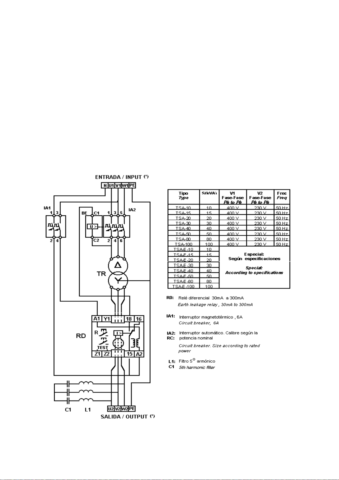
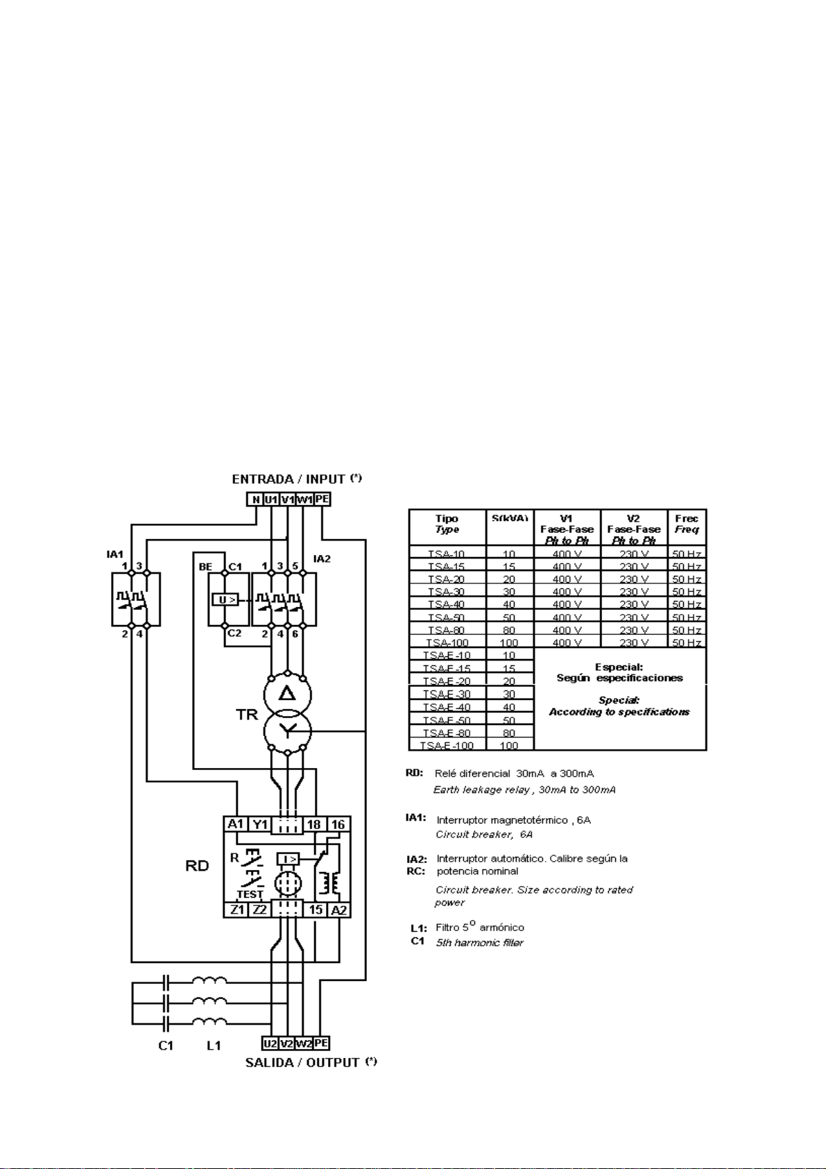
3 DESCRIPCIÓN DEL FILTRO TSA. (Ver esquema)
El filtro separador TSA está formado por las siguientes partes:
TRANSFORMADOR SEPARADOR:
Primario:
Secundario:
El centro de la estrella se conecta únicamente al conductor de tierra de protección (PE)
Bornes de salida: U2, V2, W2, PE ,
FILTRO LC:
INTERRUPTOR AUTOMÁTICO TRIPOLAR DE POTENCIA:
potencia del TSA. Corta todo el equipo por el lado de primario. El interruptor dispara en caso de
detectar fuga en el secundario.
INTERRUPTOR MAGNETOTÉRMICO BIPOLAR DE MANDO: P
mando.
RELÉ DIFERENCIAL:
(secundario del transformador). El relé estándar incorporado al TSA es ajustable de 30mA a 300mA
y dispone de retardo regulable.
4 CARACTERÍSTICAS TÉCNICAS
Los filtros TSA se diseñan muchas veces bajo especificaciones especiales, no obstante las
características técnicas esenciales son:
Conexión triángulo.
Conexión estrella, habitualmente con salida de 230 V entre fases , sin neutro.
Filtro de 5º armónico
Este relé protege el sistema de las posibles fugas en el circuito de carga
Con las siguientes características:
Bornes de entrada: U1, V1, W1, N, PE
(Ver esquema)
Dimensionado de acuerdo a la
rotege el circuito de
(Ver esquema)
Transformador
Tensión de primario estándar ........................... 400 V entre fases
Tensión de secundario estándar ........................... 230 V entre fases
Tensión de cortocircuito ucc% ........................... 6%
Potencia kVA ........................... Según tipo
Norma constructiva ........................... EN 60 742
Filtro
Frecuencia de resonancia ........................... 225 Hz
4.1 Tipos y componentes (ver esquema)
TIPO TR
(kVA)L1trifásica
TSA-10 10 R-15-400 CV-40-10 WRTR-35/03 1 20
TSA-20 20 R-15-400 CV-40-10 WRTR-35/03 1 40
TSA-30 30 R-15-400 CV-40-10 WRTR-35/03 1 63
TSA-40 40 RB-30-400 CV-40-20 WRTR-35/03 1 80
TSA-50 50 RB-30-400 CV-40-20 WRTR-35/03 1 100
TSA-80 80 RB-30-400 CV-40-20 WRTR-35/03 1 160
TSA-100 100 RB-30-400 CV-40-20 WRTR-35/03 1 250
C1 RD IA1
(A)
IA2
(A)
Page 4

4.2 Dimensiones:
TIPO A B H
TSA-10
TSA-15
TSA-20
TSA-30
TSA-40
TSA-50
TSA-80
TSA-100
5 INSTALACIÓN Y CONEXIONES.
5.1 Recomendaciones importantes!
Las cargas deben conectarse en el lado de secundario marcado como SALIDA / OUTPUT entre
•
fases (U2-V2 , V2-W2 , W2-U2 , ver esquema)
505
505
505
740
740
740
740
740
580
580
580
880
880
880
880
880
780
780
780
1050
1050
1050
1050
1050
Para obtener la máxima efectividad del filtro TSA , las cargas deben conectarse de la forma más
•
equilibrada posible entre los pares de fases (U2-V2 , V2-W2 , W2-U2 , ver esquema)
No conectar nunca cargas entre una fase y el conductor de protección , PE.
•
Las cargas que no producen armónicos múltiplos de 3, como alumbrado de incandescencia,
•
calefacción, etc., no necesitan ser conectadas a la salida del TSA, con lo cual se evita
sobrecargarlo. Pueden conectarse entre fase y neutro en el lado de primario.
La conexión a la red debe hacerse por la regleta del lado indicado como ENTRADA / INPUT.
•
Las tres fases se conectarán a U1, V1 , W1 y el neutro a N.
circuito de mando y no debe conectarse al lado de carga
El conductor de tierra de la instalación (verde-amarillo) debe conectarse al borne de entrada PE.
•
La conexión de las cargas debe efectuarse por el lado indicado como SALIDA / OUTPUT ,
•
bornes U2, V2, W2 , sin utilizar neutro (Ver esquema)
Téngase en cuenta que la salida es de 220 V entre fases. Por tanto todas las cargas deben
•
conectarse entre dos fases. Si previamente las cargas se alimentaban entre fase y neutro , esto
obliga a una redistribución de las cargas entre los pares de fases (U2-V2, V2-W2, W2-U2) , ver
esquema.
Como conductor de tierra para las cargas se tomará el ya existente , conectándolo al borne de
•
salida marcado como PE
El neutro se emplea sólo para el
. (ver fig.1)
Regular la sensibilidad del relé diferencial de acuerdo a las necesidades. La regulación debe
•
dejarse a 30mA para potencias inferiores a 50 kVA y a 300mA para potencias superiores. Caso
de disparo del relé , comprobar el buen aislamiento de los circuitos por el lado de carga.
Page 5
NOTA:
regulación superior , debido a que los filtros de EMI que incorporan presentan una pequeña fuga
cada uno , que acumuladas pueden dar una corriente superior.
6 RECOMENDACIONES PARA EL MANTENIMIENTO.
Comprobar periódicamente con el pulsador de test del relé diferencial , que éste actúa
•
Comprobar periódicamente que al ir añadiendo cargas no se sobrepase la potencia nominal del
•
En caso de añadir cargas procúrese que el reparto entre fases sea lo más equilibrado posible.
•
7 ESQUEMA
En las instalaciones con muchos terminales de informática puede ser necesaria una
correctamente.
equipo.
Repartir las cargas entre los pares de fases (U2-V2, V2-W2, W2-U2) , ver esquema
Page 6

ISOLATION TRANSFORMER
FOR 3
rd
HARMONIC FILTERING
TSA
INSTRUCTIONS MANUAL
M-981231-01A
Page 7
1 INTRODUCTION
There is a lot of electrical supply installations where most of the loads are single phase, supplying a
rectifier plus a filter . This case is very common in office buildings, big stores, TV studies, where
there is a lot of computers and electronic devices using DC supply.
rd
In such installations there is a particular type of problem with harmonics of 3
order and their
multiples (called some times “the triplens”). The current of the triplens add on the neutral in phase,
instead of adding like vectors at 120º. Because of that , the current at the neutral may be higher than
the current at the phase cables, even in case that the three phases are perfectly balanced. This causes
unexpected tripping of thermal protections and overheating of the neutral cables.
TSA
The
filters are the optimal solution to solve such problems , since the filtering of third
harmonic by other types of passive filters may cause the saturation of transformers and may spoil
the situation instead of improving. The basis of the
TSA
is a three phase D-Y isolating transformer,
which eliminates the third harmonic upstream. At the output there is also a wide band passive filter
to damp down the 5
th
and 7th harmonics.
2 LOCATION AND SIZE OF THE TSA FILTERS.
2.1 Where to locate the TSA?
It is important to locate the TSA as close as possible to the disturbing loads. Because of that we
don’t recommend the solution of big centralized TSA filters to compensate the whole power
distribution. It’s better to split up the filter in several smaller filters, placed as close as possible of
the single phase lines causing the disturbances. In that way the currents upstream the TSA will be
practically exempt of 3rd harmonic.
2.2 How to size the TSA?
The TSA filters are selected by its total power in kVA , but to calculate the current that they can
deliver , a power factor correction must be applied. Such power factor depends on the distortion of
the current that the TSA must supply downstream to the loads. To calculate the kVA of the TSA ,
the fundamental and the most significant harmonics to be supplied to the load side must be known
and then the rated power may be calculated according to the following formula.
Where :
n
SVA U I n
U
I
1
=
() , * ** (*%)
C
1732
is the phase to phase voltage at the secondary side (usually 220V or 230V)
C
1
∑
1
is the fundamental current at the load side.
I
100
2
n
n is the harmonic order
%I
is the % of harmonic n (Including the 3rd harmonic to be filtered)
n
The coefficient
n
=
FS n
∑
1
I
(*%)
n
100
2
is named the “overload factor”
REMARK:
The current written in the characteristics plate is the rated current given by the
weighted addition of fundamental and all the harmonics as follows:
n
In
*
1
∑
1
I
(*%)
n
100
2
Page 8
3 TSA FILTER DESCRIPTION. (See schematics).
The TSA filter is formed by the following parts :
ISOLATION TRANSFORMER:
Primary side:
Secondary side:
is not used in the load. The star point is connected to the protection earth cable (PE).
terminals: U2, V2, W2., PE
LC FILTER:
THREE PHASE POWER CIRCUIT BREAKER:
TSA. The circuit breaker is placed at the primary side. The breaker trips in case that an earth
leakage is detected at the secondary side circuit.
SINGLE PHASE AUXILIARY SUPPLY CIRCUIT BREAKER:
leakage relay and other auxiliary protection circuits.
EARTH LEAKAGE RELAY:
side. The standard protection relay is adjustable from 30mA to 300mA and has an adjustable delay.
4 TECHNICAL CHARACTERISTICS
TSA filters are often designed under particular specifications, but all of them have a set of common
characteristics which are listed below.
5th harmonic filter
Delta connection.
Star connection, usually with 230 V phase to phase. The neutral conductor
With the following characteristics.
Input terminals: U1, V1, W1, N , PE
(see wire diagram)
The size depends on the rated power of the
This breaker protects the earth
This relay provides a protection in case of earth leakage at the load
(see wire diagram)
Output
Transformer
Standard primary voltage ........................... 400 V phase to phase
Standard secondary voltage........................... 230 V phase to phase
Short circuit voltage ratio ucc% ........................... 6%
Power kVA ........................... Depending on type
Constructive standards ........................... EN 60 742
LC Filter
Resonance frequency ........................... 225 Hz
4.1 Types and components (see wire diagram)
TYPE TR
(kVA)L1Three phase
TSA-10 10 R-15-400 CV-40-10 WRTR-35/03 1 20
TSA-20 20 R-15-400 CV-40-10 WRTR-35/03 1 40
TSA-30 30 R-15-400 CV-40-10 WRTR-35/03 1 63
TSA-40 40 RB-30-400 CV-40-20 WRTR-35/03 1 80
TSA-50 50 RB-30-400 CV-40-20 WRTR-35/03 1 100
TSA-80 80 RB-30-400 CV-40-20 WRTR-35/03 1 160
TSA-100 100 RB-30-400 CV-40-20 WRTR-35/03 1 250
C1 RD IA1
(A)
IA2
(A)
Page 9

4.2 Dimensions:
TYPE A B H
TSA-10
TSA-15
TSA-20
TSA-30
TSA-40
TSA-50
TSA-80
TSA-100
5 INSTALLATION AND SET-UP.
5.1 Important remarks!
• Loads at the secondary side must be connected at the SALIDA / OUTPUT side phase to phase.
(U2-V2 , V2-W2 , W2-U2 , see wire diagram)
505
505
505
740
740
740
740
740
580
580
580
880
880
880
880
880
780
780
780
1050
1050
1050
1050
1050
• To get the maximum effectiveness of the TSA filter the loads must be as balanced as possible
between the three possible pairs of phases (U2-V2 , V2-W2 , W2-U2 , see wire diagram)
• Never connect a load between a phase and the PE (protection earth) cable.
• Loads which do not produce 3rd harmonic, as incandescent lighting, heating, etc., do not need to
be connected to the TSA output. They can be connected at the primary side between phase and
neutral
• The TSA must be connected to mains by the side named ENTRADA/INPUT. The three phases
shall be connected to U1, V1, W1and the neutral to N.
supply for the protection elements. Do not connect it to the load side.
• Connect the PE terminal of the TSA to the protection earth cable in the existing installation.
• Loads to be filtered must be connected to the side named SALIDA/OUTPUT. Terminals U2,
V2, W2 without the neutral (see wire diagram)
The 230 V output is phase to phase.
•
phase. If the TSA is mounted in an existing installation where loads were supplied between
phase and neutral , a new distribution has to be made, trying to keep the maximum balance
between the pairs of phases (U2-V2, V2-W2, W2-U2) , see wire diagram.
• The earth cable to be distributed to the load is the already existing earth , connected to PE
All the single phase loads must be connected phase to
The neutral is used only as auxiliary
(see fig.1)
• Adjust the sensitivity and the desired delay for the earth leakage relay according to the load
needs and the desired selectivity. For TSA units with rated power below 50 kVA , adjust in the
Page 10
low range (30 to 100mA) For higher powers the threshold can be increased up to 300mA. In
case that the relay trips, check the leakage current.
REMARK! :
controllers , etc. , the trip threshold of leakage relay must be increased due to the EMI filters
leakage.
6 TROUBLE SHOOTING AND MAINTENENCE.
• Check periodically that the earth leakage relay operates properly. Use the test push button of the
relay.
• Check periodically that the rated power of the TSA is not surpassed because of the addition of
new loads. (Take into account the overload factor due to harmonics)
• If new loads have to be added, take care of the load balance. Split the loads up in the three line
pairs (U2-V2, V2-W2, W2-U2) , see wire diagram.
7 SCHEMATICS
In case that the loads are mainly single phase supplying computers, printers, speed
 Loading...