

Page 1
22 2324
16 1718 19 2021
TR16-RS485-25A
Voltage and direct current multi-channel analyser
IMPORTANT!
DC power supply of TR16 must be protected by fuses, circuit-breaker or any
other devices providing overcurrent protection. This devices must be set according to the DC installation power.
The equipment must be connected to a fuse-protected power circuit, in accordance
with its power supply range and consumption. In turn, the power supply circuit must
be tted with a circuit breaker switch or an equivalent device, in order to be able to
disconnect the equipment from the power supply grid. The power supply circuit must
be connected using a cable with a minimum section of 1 mm2.
IMPORTANT!
If a transformer not specied by the manufacturer is connected,
or it is connected to a different primary current than that specied
in this manual, the current measurement will be incorrect and the
device's protection may be compromised.
If no probe is connected to the device, you must make a bridge
between the three terminals meant for the probe. (7, 8, 9).
The leading device connected to the main network, registers all the memory addresses of the sub-slave devices connected to it, thus reducing the number of nodes to
be queried along the communications bus by the communications master, therefore
reducing the pooling time.
The typology and the connections setup is described in DIAGRAM B
5. CONFIGURATION
In that relating to the measurement of voltage or direct current, the device does not
require any special type of conguration, as the internal adjustment conguration
ranges come set from the factory.
1. DESCRIPTION OF THE DEVICE
The TR16-RS485 is a measurement device for up to sixteen direct current channels
and a voltage channel of up to 1000 V of direct voltage. The measurement of the
current is done by means of sixteen Hall effect transformers (transformer for measuring direct current), with 25 A primary.
The device has 2 RS-485 communications ports. The first of these is used to
connect and transmit the information to the master by means of the Modbus/RTU
protocol. The second communications port, allows for setting up a multi-master type
of communications typology (see section 4.5. Connection diagram of the RS-485
slave and sub-slave connection bus), given the multitude of applications that can
be comprised by a large number of TR16-RS485 analysers. The communications
parameters can be congured by using the selectors located on the front panel of
the device.
Moreover, this device is equipped with 3 (logical) digital inputs, for detecting the
status of digital signals, coming from the device's surroundings and the information
of which is also available via RS-485 communication. Apart from the digital inputs,
the device is equipped with an analogue input with a 0...20 mA range and an input
for a congurable Pt100 or Pt1000 probe.
2. PRELIMINARY CONSIDERATIONS
2.1 Verications on receiving
Upon receiving the instrument verify the compliance of the following points:
• The device corresponds to the specications of your order.
• Verify that the device has not been damaged in transit
2.2 Safety precautions
For the safe use of the device, it is essential that the people who install or handle it
follow the usual safety measures, as well as the warnings documented in the said
instructions manual.
The TR16-RS485 device has specically been designed to be installed inside an
electric or enclosed cabinet, fastened to a DIN rail. Under no circumstances may
the device be installed or integrated into a place where it is in direct contact with
people. The TR16-RS485 is tted with a blinking red LED light (CPU), which warns
that it is running, and therefore warns of the presence of voltage and current in the
electronic circuit. Even though the LED light is not on, this does not free the user of
verifying that the device is disconnected from all power sources.
3. INSTALLATION AND START-UP
This manual contains information and warnings that the user must adhere to in
order to guarantee the safe operation of the device, and maintain it in a good state
with regards to safety. In its usual operation it should not be used until it has been
mounted in its nal location in the electric cabinet.
IMPORTANT!
If the equipment is used in a manner not specied by the manufacturer,
the device's protection may be compromised.
When it is probable that the device may have lost its safety protection (for example,
if visible damage can be seen), the device must be disconnected from the power
supply. In this case, contact the qualied technical service or otherwise contact our
Technical assistance Service (see section 7. TECHNICAL ASSISTANCE SERVICE).
3.1 Equipment installation
The installation of the device is of the DIN rail type; it has a surface of 9 DIN modules (160 mm), and a height of 58 mm. All the connections remain accommodated
inside the electric cabinet.
Take into account that with the equipment connected, the terminals and the opening
of the covers or the elimination of elements, may give access to parts that it is hazardous to touch. The equipment must not be used or powered up until its installation
has been fully completed.
3.2 Power supply of the equipment
The device has two auxiliary power supply inputs; one for alternating current and the
other for direct current. Under no circumstances may the user connect both power
supply inputs simultaneously.
Power Supply AC DC
Nominal voltage 230 V ac ≈ 24 V dc =
Power supply tolerance ± 20% ± 10%
Frequency 50 Hz -
Equipment consumption without transformers 2 V·A 2 W
Equipment consumption with 16 sensors (without load) 14 V·A 8 W
Equipment consumption with 16 sensors (with current load) 24 V·A 14 W
Operating conditions
Operating temperature -10 ... 65 ºC
Relative humidity 5...95 RH without condensation
Maximum operating height 2,000 metres
Protection IP20
TR16-RS485 accuracy
Current measurement (without current sensor) ± 0.5 %
Minimum current threshold 350 mA
Voltage measurement ± 1 %
Temperature ± 3 ºC (-30 ... 80 ºC)
Temperature input accuracy
Pt100 / Pt1000 temperature probe ± 3 ºC
Analogue input accuracy
Input accuracy 0...20 mA ± 0.5 %
Input impedance 165 Ω
Resolution in dots 1024 dots
Converter resolution 10 bits
Safety
Category III – 300 V AC (EN61010)
Double-insulated electric shock protection class II
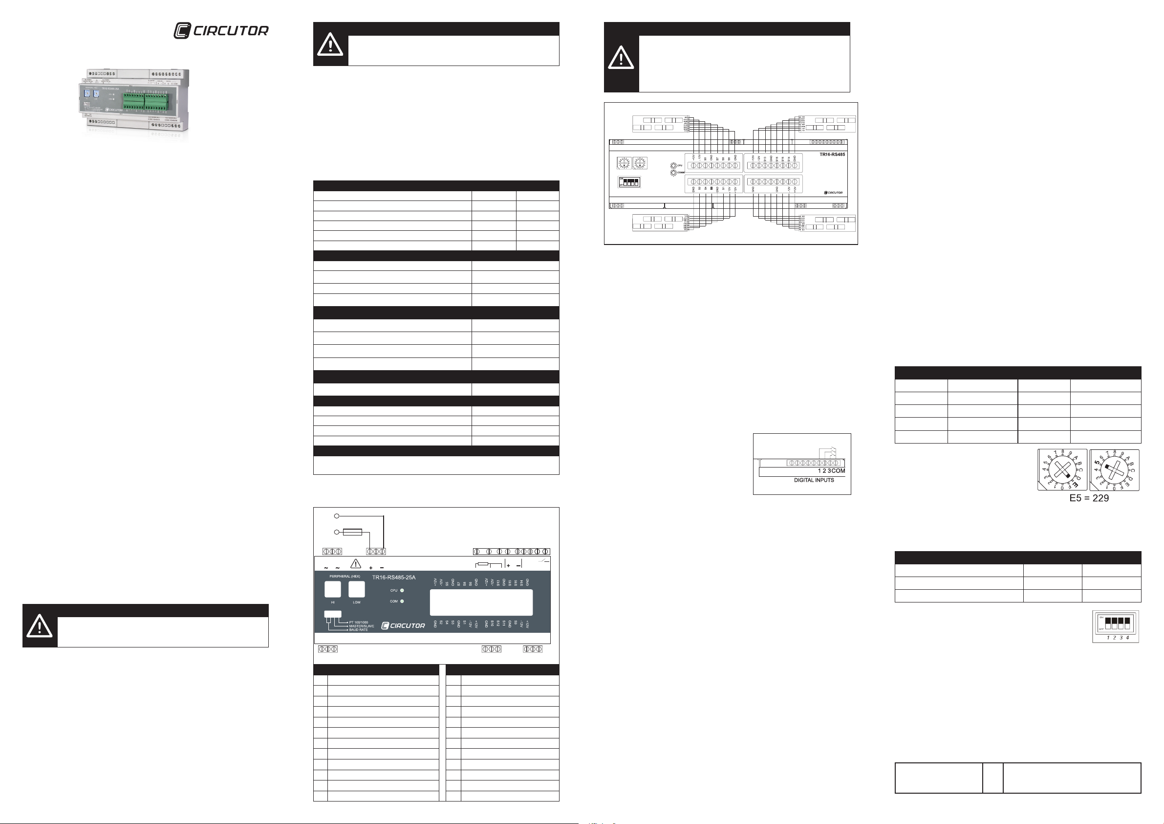
4. CONNECTIONS
4.1 Description of the connection terminals
1A / 250V
1 2
AC POWER
SUPPLY 230 Vac
Vd2 Vd1
Vd(1000Vdc)
3 4 5 6
AC POWER
SUPPLY 24 Vdc
7 8 9 10 11 12
Pt 100/1000 ANALOG
A(+) S(GND) B(-)
COM1 RS485/S
Description Description
1 Power supply 230 Vac (phase or neutral) 13 Digital input 2
2 Not used 14 Digital input 3
3 Power supply 230 Vac (phase or neutral) 15 Common digital inputs
4 Power supply 24 Vdc (positive) 16 Direct voltage (positive)
5 Not used 17 Not used
6 Power supply 24 Vdc (negative) 18 Direct voltage (negative)
7 Pt100 / Pt1000 probe input 19 Slave RS485 port (A – positive)
8 Pt100 / Pt1000 probe input 20 Slave RS485 port (S – GND)
9 Pt100 / Pt1000 probe input 21 Slave RS485 port (B – negative)
10 Analogue input 0...20 mA (positive) 22 Master RS485 port (A – positive)
11 Analogue input 0...20 mA (negative) 23 Master RS485 port (S – GND)
12 Digital input 1 24 Master RS485 port (B – negative)
13 14 15
DIGITAL
|1 |2 |3 COM
A(+) S(GND) B(-)
COM2 RS485/M
4.2 Connection diagram of the current transformers
The TR16-RS485 is a device designed to measure up to 16 direct current lines
simultaneously. The device is equipped with 16 inputs for Hall effect transformers,
with which one can measure up to 25 A per direct current channel.
Detailed connection diagram of the M/TR transformers
For connecting the M/TR-25A to the TR16-RS485, device, the use of a screened
cable is recommended, the mesh of which must solely be connected to the GND
connector on the device.
Optionally, up to a maximum of four M/TR-25Ax4 modules (16 channels) can be connected to the TR16-RS485 device. After initialising, the equipment performs a scan
of all the inputs of the transformer modules, disabling the unused, and consequently
not physically connected inputs, by software. In the event that a new four transformer
M/TR module is subsequently connected, the user must reset the device's power
supply, for the four new current measurement transformers to be recognised.
4.3 Connection diagram of the digital inputs
The TR16-RS485 device has three voltage-free
inputs and a voltage of 24 V DC on the common one for detecting the logical status of the
external pickups. On a real-time basis it detects
the status of the inputs (open contact or closed
contact), and transmits this information through
the RS-485 communications bus.
The use and cabling of the said inputs is entirely optional and its implementation
does not affect the operation of the rest of the assembly.
4.4 Connection diagram of the conventional RS-485 communications
bus
The TR16-RS485 has an RS-485 communications port for real-time connection
with a master PLC or SCADA industrial control type communications system. The
communication must be made using a twisted-pair mesh-screened communications
cable, with a three-core minimum. Between the master system and the last peripheral, the systems allows for a maximum distance of 1,200 metres. A maximum
of 32 parallel-connected peripherals may be connected to the communication bus,
for each port used.
In any event, star-type installations must be avoided, as the communications bus
output of a peripheral must be chained to the input of the next and successive ones.
For installing these devices, it should be noted that there is no prior need of any type
of end-of-line resistor. SEE DIAGRAM A
4.5 Connection diagram of the RS-485 slave and sub-slave communications bus
The TR16-RS485 has a second communications bus, which has the purpose of
being able to communicate with other TR16-RS485s in a parallel manner (subslave devices).
The nodes connected to the main bus, can simultaneously be connected to 15 new
devices. Therefore, at the main bus level, a maximum of 32 devices can be installed,
plus 15 sub-slave devices per installed node.
This communications typology results in the installation of 512 nodes on a single
communications network, without this fact penalising the pooling time of the main
M98234101-03-15A
communications bus.
5.1 Communications
The implemented communications protocol is of the MODBUS/RTU® type.
As shown in the connection diagrams, the TR16-RS485 peripheral is connected to a
control system by means of the RS-485 bus. For this purpose, each of the devices
S9
S11
S10
S12
must be assigned a node number to identify them within the communications bus.
The front panel of the device is tted with rotary switches and MINI-DIP switches
that allow the user to adjust the parameters of the different communications settings.
To integrate the device in the bus, only the node or peripheral number and the
transmission speed of the RS-485 bus need to be set, which must naturally be the
same as that of the communications master.
By default, the communication is set to 1 stop bit, Parity No and 8 bits in length
(8/N/1).
5.2 Setting the peripheral number.
The two rotary switches on the front panel of the device, are used to set the peripheral number (node). As the device communicates in Modbus/RTU protocol, the
peripheral or station number may vary in the range 1 to 255 (FF in hexadecimal).
The node number is set in hexadecimal format; under no circumstances may this
be set in decimal format. See several examples of the conversion of decimal to
hexadecimal:
Decimal Node Hexadecimal Node Decimal Node Hexadecimal Node
10 0A 80 50
15 0F 150 96
25 19 180 B4
50 32 200 C8
65 41 255 FF
For the hexadecimal node number, the rst
digit is set with the left-hand switch and the
second with the right-hand switch. After the
device number has been set, it is not necessary to reset the device.
5.3 Setting the transmission speed
The TR16-RS485 has a module with four (MINI-DIP) switches, which allow the
transmission speed to be set using switches 1 and 2. See the following table:
Transmission speed Switch 1 Switch 2
9,600 / 8 / N / 1 OFF OFF
19,200 / 8 / N / 1 OFF ON
38,400 / 8 / N / 1 ON OFF
When a change is made to the transmission speed, it is not
necessary to reset the device. Nor when the node (peripheral)
number is changed.
5.4 Setting slave and sub-slave devices
Using switch number 3, the user can set the type of communications typology. The
device may be set as a conventional slave of a communications network, or otherwise as a sub-slave within a multislave network.
5.4.1 Slave devices
In DIAGRAM A, the communications bus is of a conventional communications typology. In this type of typology the peripherals may be numbered from 1 to 255 (from
01 to FF in hexadecimal).
Position of Switch 3
Diagram A
OFF
The numbering of the node numbers
may vary between 1 and 255 (from
01 to FF in hexadecimal).
Page 2
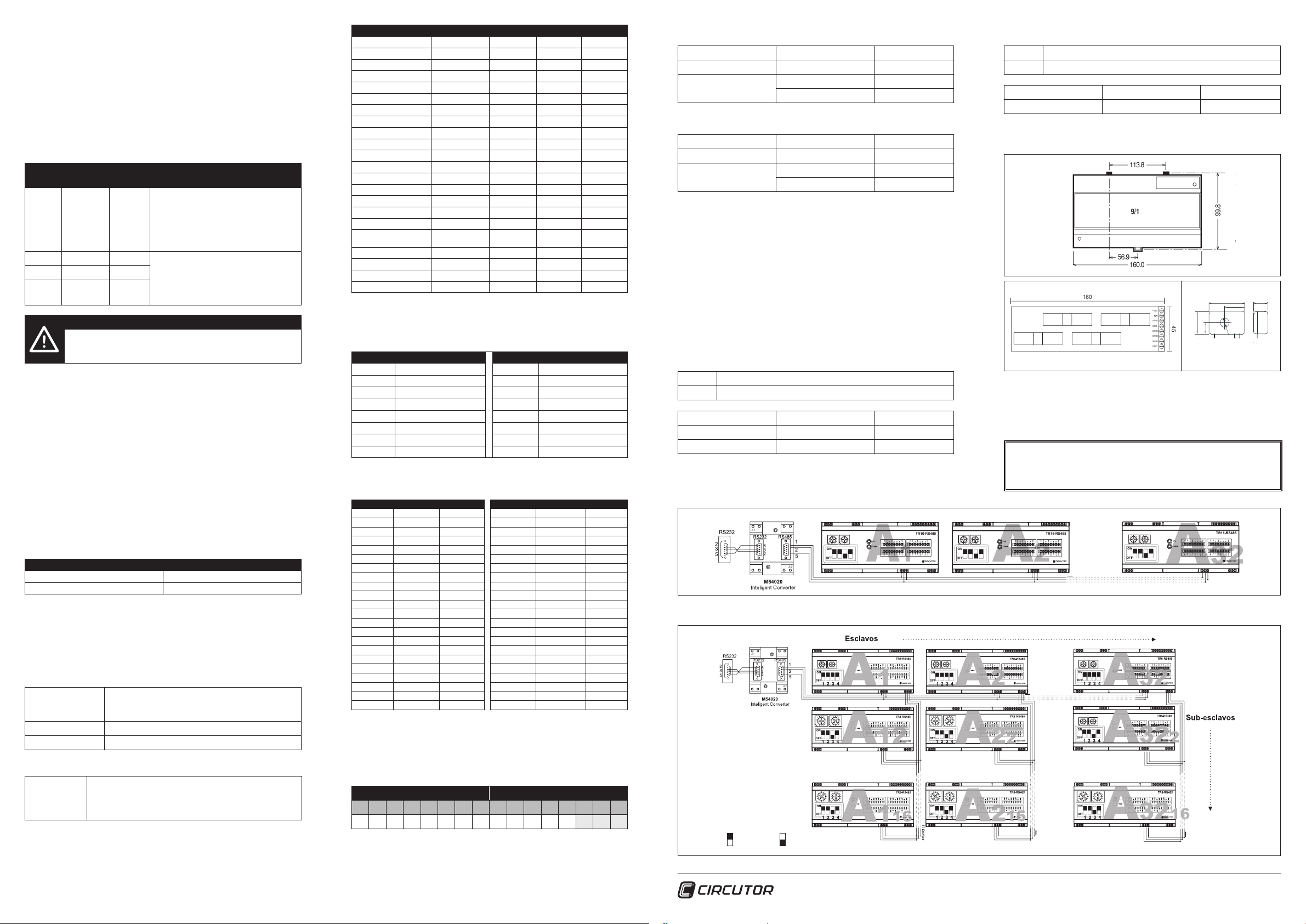
5.4.2 Sub-slave devices
106.0
6/1
x
y
x
y
y
99.8
30.2
60.6
(pitch of wall mounting
holes in din rail clips)
160.0
9/1
113.8
56.9
99.8
y
160
45
+12V
S5/S1
GND
GND
S6/S2
S7/S3
S8/S4
15
5
For communications systems with slaves and sub-slaves (DIAGRAM B. Connection
diagram of the RS-485 slave and sub-slave communications bus), the communica-
tions of the devices marked as sub-slave (A12, A22 ,,, A322 ... A116, A216 ,,, A3216 ) must
have different settings and a node numbering system in order.
The slave nodes (A1, A2 ... A32 ), the same as specied in the previous section, can
be numbered from peripheral 1 to 255 (from 01 to FF in hexadecimal). On the other
hand, the sub-slave nodes of each of the communications buses, must be numbered from 2 to 16 (from 02 to 10 in hexadecimal), and consecutively in each of their
related buses. The slave devices cannot detect the presence of sub-slave devices
with node numbers above 16 (10 in hexadecimal).
Equip-
ment:
Switch 3
Decimal
Node
The numbering of the node numbers may
vary between 1 and 255 (from 01 to FF
A1 ON 01
in hexadecimal). Under no circumstances
may they be duplicated, and they need
not be assigned in a logical or sequential
order.
A1
... OFF --
A1
OFF 02 The numbering of the node numbers
2
may vary between 2 and 16 (from 02 to
10 in hexadecimal) and must be sequen-
16
OFF 16
tial, without leaving any node numbers
unassigned.
IMPORTANT!
If new sub-slaves are added, the slave device must be reset
(leading bus: A1, A2 ... A32 ). For example, if device A23 is added,
device A2 must be reset.
This operation is required so that the leading element performs a scan of the entire
communications bus an implements all the information from its sub-slave devices
in its memory map.
5.5 Analogue input and temperature probe
The TR16-RS485 is equipped with an analogue input to connect a probe or an
industrial sensor. The analogue input behaves in a linear manner, delivering by
transmission the analogue measurement in resolution dots (from 0 to 1024 dots).
The communications master is responsible for converting the said dots to physical
values that the user can understand.
Moreover, the equipment has an input for the connection of a Pt100 or Pt1000 type
temperature probe. To connect one or the other type of probe (Pt100 or Pt1000),
it must be selected by using the fourth switch located on the front panel. Once the
switch has been set, the equipment sends the temperature value in degrees centigrade by communication.
Temperature probe Switch 4
Pt100 ON
Pt1000 OFF
5.6 Modbus protocol
The TR16-RS485 peripheral uses the MODBUS© protocol. Within the MODBUS©
protocol, the RTU (Remote Terminal Unit) mode is used; every 8-bits per byte in a
message contains two 4-bit hexadecimal characters.
The format for each byte in RTU mode is:
Code
Bits per byte 8 data bits
Check-Error eld CRC (Cyclical Redundancy Check) type
Implemented Modbus functions:
Functions 03
and 04
5.6.1 Modbus/RTU® memory map
This table shows the Modbus addresses of the conventional slave device. In the
successive tables (from module 2 on), the memory addresses are displayed for the
sub-slave devices, if these are connected.
8 binary bits, hexadecimal 0-9, A-F
2 hexadecimal characters contained in each 8-bit eld
of the message.
Function used for reading the parameters measured by the
TR16-RS485. All the electric parameters are 16 bit words,
so that to request each parameter one Word (2 bytes – XX)
is needed.
Description Abbreviation Symbol Address Unit
Input current 1 M1-MLC1 I 1 0000 A x 100
Input current 2 M1-MLC2 I 2 0001 A x 100
Input current 3 M1-MLC3 I 3 0002 A x 100
Input current 4 M1-MLC4 I 4 0003 A x 100
Input current 5 M1-MLC5 I 5 0004 A x 100
Input current 6 M1-MLC6 I 6 0005 A x 100
Input current 7 M1-MLC7 I 7 0006 A x 100
Input current 8 M1-MLC8 I 8 0007 A x 100
Input current 9 M1-MLC9 I 9 0008 A x 100
Input current 10 M1-MLC10 I 10 0009 A x 100
Input current 11 M1-MLC11 I 11 000A A x 100
Input current 12 M1-MLC12 I 12 000B A x 100
Input current 13 M1-MLC13 I 13 000C A x 100
Input current 14 M1-MLC14 I 14 000D A x 100
Input current 15 M1-MLC15 I 15 000E A x 100
Input current 16 M1-MLC16 I 16 000F A x 100
Differential Voltage M1-VDG Vd 0010 V x 10
Pt100/Pt1000
temperature
Analogue input M1-ANAL 0012 Dots
Digital inputs M1-DIG 0013 0 / 1
Not used 0014
Peripheral number M1-PERIPH 0015
M1-TEMP Pt100/Pt1000 0011 ºC
In the successive tables (from sub-slave 2 on), the initial addresses of the modules
are shown, taking into account that they all have the same distribution available to
the leading bus device.
Module Addresses Module Addresses
2 0016 to 002B 10 00C6 to 00DB
3 002C to 0041 11 00DC to 00F1
4 0042 to 0057 12 00F2 to 0107
5 0058 to 006D 13 0108 to 011D
6 006E to 0083 14 011E to 0133
7 0084 to 0099 15 0134 to 0149
8 009A to 00AF 16 014A to 015F
9 00B0 to 00C5
Examples of the memory addresses of some of the sub-slave devices, if these are
connected.
Module 2 Address UDS Module 3 Address UDS
M2-MLC1 0016 A x 100 M3-MLC1 002C A x 100
M2-MLC2 0017 A x 100 M3-MLC2 002D A x 100
M2-MLC3 0018 A x 100 M3-MLC3 002E A x 100
M2-MLC4 0019 A x 100 M3-MLC4 002F A x 100
M2-MLC5 001A A x 100 M3-MLC5 0030 A x 100
M2-MLC6 001B A x 100 M3-MLC6 0031 A x 100
M2-MLC7 001C A x 100 M3-MLC7 0032 A x 100
M2-MLC8 001D A x 100 M3-MLC8 0033 A x 100
M2-MLC9 001E A x 100 M3-MLC9 0034 A x 100
M2-MLC10 001F A x 100 M3-MLC10 0035 A x 100
M2-MLC11 0020 A x 100 M3-MLC11 0036 A x 100
M2-MLC12 0021 A x 100 M3-MLC12 0037 A x 100
M2-MLC13 0022 A x 100 M3-MLC13 0038 A x 100
M2-MLC14 0023 A x 100 M3-MLC14 0039 A x 100
M2-MLC15 0024 A x 100 M3-MLC15 003A A x 100
M2-MLC16 0025 A x 100 M3-MLC16 003B A x 100
M2-VDG 0026 V x 10 M3-VDG 003C V x 10
M2-TEMP 0027 º C M3-TEMP 003D ºC
M2-ANAL 0028 Dots M3-ANAL 003E Dots
M2-DIG 0029 0 / 1 M3-DIG 003F 0 / 1
Not used 002A 0040
M2-PERIPH 002B M3-PERIPH 0041
5.6.2 Reading of the status of the digital inputs (DIG)
The DIG variable, like the rest of the electric variables, is a record (1 word = 2 bytes),
in other words, in hexadecimal it would be 0xFFFF. The inputs go from 1 to 3 and
these represent the 3 lower weight bytes:
HIGHEST WEIGHT BYTES LOWEST WEIGHT BYTES
7 6 5 4 3 2 1 0 7 6 5 4 3 2 1 0
0 0 0 0 0 0 0 0 0 0 0 0 0 I3 I2 I1
To know the Modbus memory addresses, refer to section 05.06.01 Memory map.
The value of each input determines if it is activated (1) or deactivated (0).
Example 1 (in master device):
TX NP 0400090001 CRC
Input activated 3
By communication
INP=0x0004 Hexadecimal
0000000000000100 Binary
Example 1:
TX NP 0407D0000F CRC
RX NP 0420 02 03 04 05 06 00 00 00 00 00 00 00 00 00 00 00 CRC
Listing of slaves 02, 03, 04, 05, 06 Hexadecimal
Decimal conversion 02, 03, 04, 05, 06 Decimal
Example 2 (in master device):
TX NP 0400090001 CRC
6. DIMENSIONS
Input activated 2 and 3
By communication
INP=0x0006 Hexadecimal
0000000000000110 Binary
5.6.3 Reading the peripheral number
The PERIPH variable, like the rest of the electric variables, is a record (1 word = 2
bytes), in other words, in hexadecimal it would be 0xFFFF. This record refers to the
peripheral number associated by using the front panel on the equipment, for each
of the slave and sub-slave devices.
5.6.4 Number and listing of sub-slave devices connected
Number of sub-slave devices: There is a Modbus record (0834), which indicates
the number of sub-slave devices connected to the communications master (see in
DIAGRAM B, devices, A2 ... A16). Said variable solely returns the numeric value in
hexadecimal, reporting the number of nodes connected to the device through the
master communications port (if it is used).
Example 1:
TX NP 0408340008 CRC
RX NP 0402 0006 CRC
Number of slaves 6
By communication RX = 0x0006 Hexadecimal
Decimal conversion 6 Decimal
Listing of sub-slave devices: As opposed to the number, the listing of sub-slave
elements connected to a master device, reports one by one, the peripheral numbers
connected to the said master device (record 07D0).
DIAGRAM A - Connection diagram of the RS-485 communications bus with slave devices (conventional bus)
SWITCH ON SWITCH OFF
DIAGRAM B - Connection diagram of the RS-485 communications bus with slave and sub-slave devices
7. TECHNICAL ASSISTANCE SERVICE
If you have any doubts about the operation of the equipment or any malfunction,
please contact the technical assistance service at CIRCUTOR SA
CIRCUTOR, SA - Technical Assistance Service
Vial Sant Jordi, s/n - 08232 Viladecavalls (Barcelona) SPAIN
Tel.: 902 449 459 (Spain) - +34 93 745 29 00
email: sat@circutor.es
25.0
12.
5
+15V -15V O/P
M98234101-03-15A
40.0
10.0ø
.
22.
5
 Loading...