

Page 1
TCP2RS+
Before performing any maintenance operations,
disconnect the unit from the power supply. If you
suspect an operational fault in the unit or in its
The TCP2RS+ is a communications gateway used to
convert the physical Ethernet environment to serial
RS-485 or RS-232 communications or vice versa in
the routing mode.
This document provides the instructions for use and describes
the operation of the TCP2RS + device. You can download the
manual from CIRCUTOR's web site in case it is misplaced:
connection modifications, repairs, etc., you must
protection system, remove the unit from service. The design of
the unit makes it easy to replace in the event of a fault.
www.circutor.com
1.- DESCRIPTION
The purpose of the TCP2RS+ device is to convert the
physical series environment to Ethernet
communications with TCP/IP communication
packets. The gateway is responsible for the
transparent conversion under TCP or UDP
connections. The operation is determined by the
parameterisation carried out in the internal
configuration web menu.
2.- COMMUNICATION
The device is equipped with a self-detecting 10BaseT
/ 100Base TX connection for the physical connection
of the TCP2RS+ converter to an Ethernet network.
For its configuration has an internal web site from
which the user can define the network protocol used
to communicate with the management software or
communications system master.
2.1.- Ethernet addressing
The device is connected to the master communication system by means of an IP connection, and the addressing parameters must be configured. The configuration modes include the assignment of a fixed IP or configuration of a DHCP name.
2.1.1.- Ethernet address assignment
To configure the IP address configuration in any of the available formats, run program IPSetup.exe, supplied with the equipment.
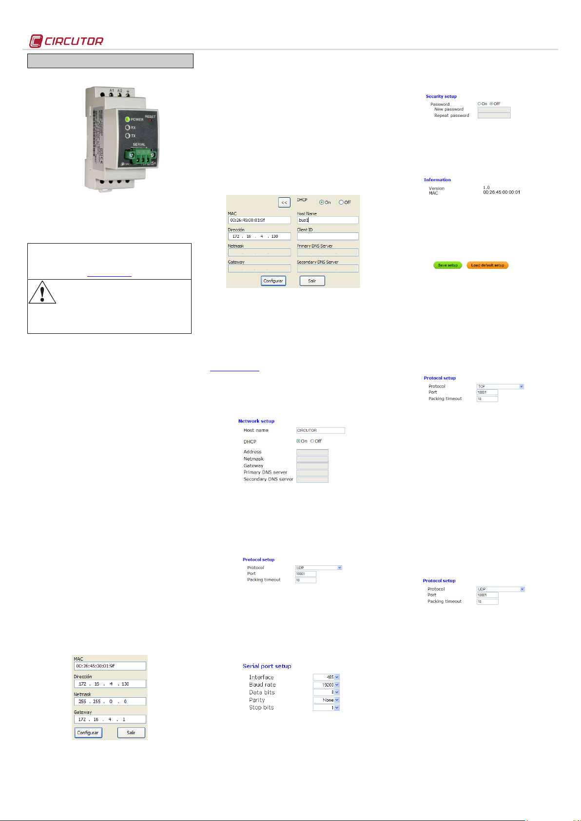
2.1.2.- Fixed IP assignment
To assign the fixed IP address, enter the MAC
address shown on the permanent side label attached
to the device, the format of which is
00:26:45:XX:XX:XX.
In the Address field, enter the IP address being
configured; do the same with the (Netmask) and the
(Gateway) port if necessary. After entering the device
settings, press “Setup” to send the configuration to
the equipment.
2.1.3.- DHCP IP assignment
To assign the DHCP name, choose this option using
the arrow on the upper right, and select On. Once the
configuration fields have been enabled, enter the
MAC address that can be seen on the permanent side
label attached to the device, the format of which is
00:26:45:XX:XX:XX. In the Address field, enter an
unused, temporary IP address, which is within the
working range of your computer. In the Host Name
field, enter the DHCP name to be assigned to the
equipment. Optionally, the user can configure the
parameters of the ClientID field. The default VendorID
of the device is CIRCUTOR.
2.2.- Configuration web site
After connecting to the Local Area Network (LAN),
and configuring the IP address or the DHCP name,
the device has an internal web site where all the
parameters related to the network protocol and
configuration of the serial port can be configured. To
access the web site, simply use a conventional
Internet browser and enter the IP address or the
name assigned to the device (for example .
http://172.16.4.130)
2.2.1.- IP address or DHCP name
The internal web site can be used by the user to
apply changes to the DHCP name or to the IP
address previously assigned to the device.
2.2.2.- Network protocol
The device can be connected to the master
communications system by means of three types of
network protocols and to a configurable port (TCP,
UDP or Modbus/TCP). In the case of the
Modbus/TCP protocol, port modification will be
disabled and fixed at 502.
2.2.3.- Configuration of the Serial port
The communications bus parameters can be fully
configured in terms of type of serial Interface (RS485/RS-232), transmission speed (from 4800 bps to
115.2 kbps), data bits (7 or 8), parity (no parity, odd
or even) and stop bit (1 or 2). The data will be
configured by default to 8 by selecting the
Modbus/TCP communications protocol.
TCP2RS+
2.2.4.- Configuration of the setup password
Password can be activated to enable the edition
password. In case to use, the access user is "admin"
and the setup password introduced.
2.2.5.- Device information
The lower part of the screen shows the firmware
version and the machine address of the device (the
same address as that shown on the permanent side
label).
2.2.6.- Save changes
Once any change has been made to the
aforementioned sections, the information must be
saved using the “Save Setup” option. If you wish to
return to the default configuration, select “Load
default setup”.
2.3.- Configuration of network protocols
2.3.1.- TCP Protocol
In the protocol stackTCP/IP, TCP is the intermediate
layer between the Internet protocol (IP) and the
application. In general, applications need reliable
communications. The IP layer offers an unreliable
datagram service (no confirmation), so the TCP adds
the functions required to offer a secure, error-free and
zero loss service for the communications between
two systems.
- Protocol: TCP Mode
- Port: Destination TCP Port Lumber
*In any case you can configure the port 80, so is the
web configuration port
- Packing timeout: maximum waiting time
2.3.2.- UDP Protocol
The User Datagram Protocol (UDP) is a messageoriented minimum transport level protocol that has
been documented in the RFC 768 of the IETF.
In the Internet protocol family, UDP provides a simple
interface between the network layer and the
application layer. UDP does not offer guarantees
during the delivery of its messages and the UDP
origin does not withhold the states of UDP messages
sent to the network. UDP only adds the multiplexing
functionality to the application and the verification
sum of the header and useful load. Any type of
guarantees for the transmission of information must
be implemented in higher layers.
- Protocol: UDP Mode
- Port: Destination UDP Port Lumber
*In any case you can configure the port 80, so is the
web configuration port
- Packing timeout: maximum waiting time
2.3.3.- Modbus/TCP Protocol
Modbus/TCP is a variation or extension of the
Modbus® protocol, which enables it to be used on
the TCP/IP transport layer. Therefore, Modbus/TCP
can be used throughout the Local Area Network or
the Internet. This was one of the objectives that
motivated its development (the specification of the
protocol was submitted to the IETF (Internet
Engineering Task Force).
M98233201-03-12A
Page 2
Power circuit:
- Humidity (no condensation) :
5 … 95%
LED symbols:
Mechanical features:
- Maximum operating height:
2,000 m
Network interface:
Serial interface:
- Stop bit
1 or 2
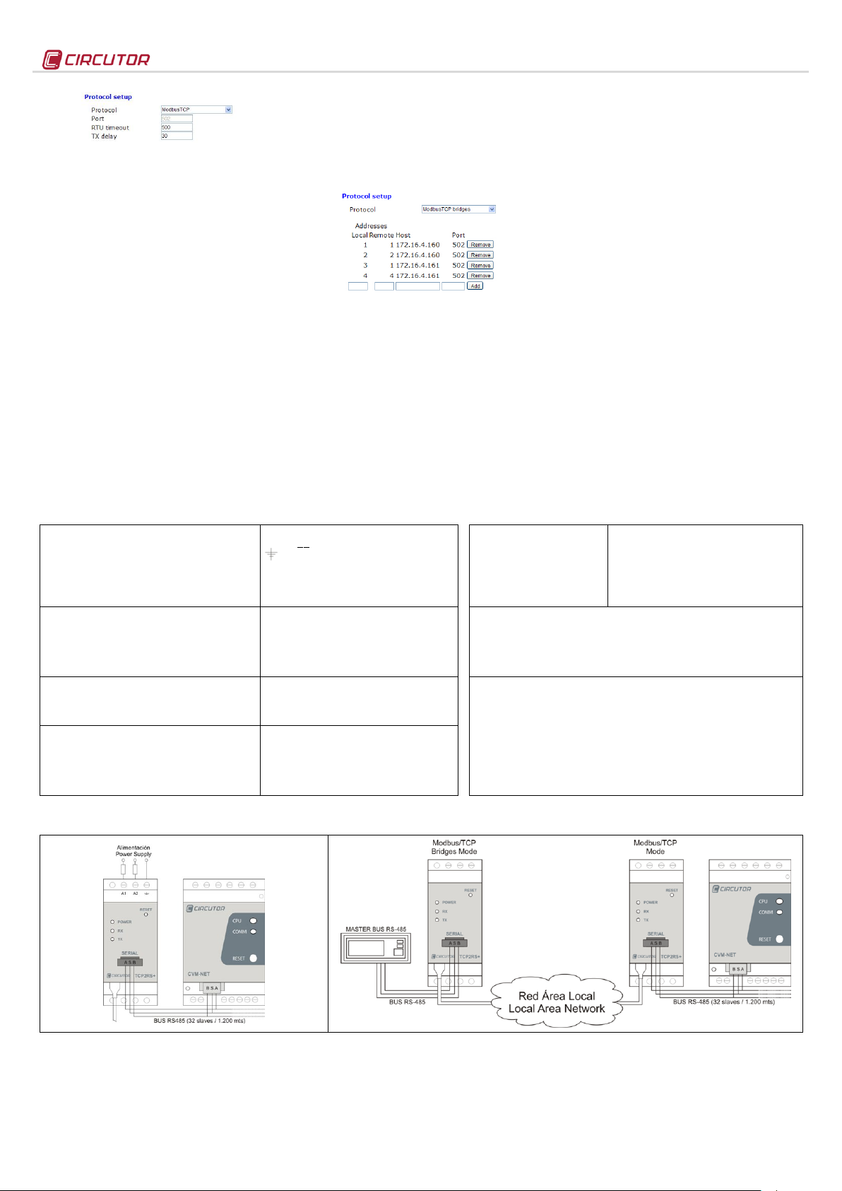
Figure 1. Standard connection of serial equipment
Figure 2. RS-485 Systems over Ethernet infrastructures (Modbus/TCP Bridges Mode)
- Protocol: Modbus/TCP Mode
- Port: Fixed port number 502
- RTU timeout: maximum bus waiting time
- TX delay: additional delay on serial RS bus
2.3.4.- Modbus Protocol/TCP Bridges (routing)
The purpose of this work mode is to implement RS485 or RS-232 networks over existing Ethernet
network infrastructures, either Local Area Networks
or remote networks.
In the Modbus/TCP Bridges mode the unit performs
a constant supervision of the Modbus RTU frames
received through the serial port of the TCP2RS+, and
its function is to address the frames in accordance
with the features programmed in the unit's
configuration web menu.
To do so, the master TCP2RS+ must be configured
with the Modbus Protocol/TCP Bridges, as shown in
Figure 2. Its purpose is to address the frames
received through the RS port, depending on the node
number and destination IP at which the Modbus
sentence is sent.
The paths must be loaded into the device before
performing the addressing operations.
The slave TCP2RS+ device(s) must be configured
with the standard procedure in the Modbus/TCP
protocol, with the serial port communications
parameters and in accordance with the equipment
that is physically connected to the RS-232 or RS-485
3.- TECHNICAL SPECIFICATIONS
communications bus (speed, parity, data bits and
stop bit).
2.3.4.1.- Loading path to the master equipment
In the case of RS-232 or RS-485 topologies over
Ethernet networks, the paths being addressed must
be loaded to the master, according the Modbus®
node number.
List of routes
TCP2RS+ can be used to address the node
numbers. In some cases, the slave equipment
located in different Ethernet networks and connected
to different TCP2RS+ can have a peripheral number
parameterised that is the same as other devices in
other IP networks.
To make sure that the user does not have to change
the node numbers, TCP2RS+ can convert the node
number in the Modbus frame, replacing the local
node number issued by the communications master
number with the real node that the equipment has
available.
In the List of routes, in the example of the Local
node No. 3, how the master sends the Modbus
command for node 03 and TCP2RS+ replaces node
TCP2RS+
03 with node 01 in the Modbus/TCP frame, sending
the Modbus command to the slave TCP2RS+
converter with 172.16.4.161. Even when there is a
different node number that is identical to that of bus
IP 172.16.4.160 (first path position), TCP2RS+ routes
the information in accordance with the node number
and Ethernet address (IP) previously loaded to the
device.
- Local Address: Local node in the master
- Remote Address: Real node in the slave
- Host: IP of the destination or slave TCP2RS+
- Port: IP Port of the destination connection (502)
2.3.4.2.- Parameterisation of IP connection ports
Modbus/TCP works in the fixed mode with TCP port
number 502. For this reason, there may be a problem
when working in remote mode, with installations
where the connection is established through a router,
in which various communication buses may operate
in parallel to slave TCP2RS+.
In the Modbus Bridges mode, TCP2RS+ allows the
random parameterisation of the connection TCP port,
receiving the prior configurations on the router
connecting to the Internet. It is worth noting that, in
this mode, the routing functions would be carried out
by the connection router first, and then by the
configuration of the internal web menu of the device
(path load).
- Single-phase (A1 – A2) :
- Earth connection terminal:
- Frequency:
- Maximum consumption:
- Working temperature:
- Case material:
- Equipment protection degree:
- Dimensions (mm):
- Weight:
- Type:
- Connector:
- Network Protocols - Accesses:
- Type:
- Transmission speed (configurable):
- Data bits:
- Parity:
4.- CONNECTIONS
85…264 Vac / 120…300 Vdc
47…63 Hz
4.6 …7.5 VA
-10 …+60 ºC
UL94 - V0 self-extinguishing plastic
IP 20
35.4 x 73 x 84.68 mm (2 modules)
120 g
Ethernet 10BaseT / 100BaseTX self-detectable
RJ45
TCP / UDP / Modbus/TCP - HTTP
RS-485 / RS-232 three wires (A/S/B) (RX/GND/TX)
4800, 9600,19200, 34800, 57600, 115200 bps
7, 8
No parity, odd, even
- Flashing power LED
- Flashing RX
- Flashing TX
- Full/Half (left in RJ45)
- 10 M/100 M (right in RJ45)
Standards:
IEC 60664, VDE 0110, UL 94, EN61010-1, EN55011, EN 61000-4-2, EN 61000-4-3,
61000-4-11, EN 61000-6-4, EN 61000-6-2, EN 61000-6-1, EN 61000-6-3, EN 61000-4-5,
CE
Safety:
Installation category Category III / EN61010 double-insulated electric shock protection
class II. The equipment must be connected to a power circuit protected with type gl fuses,
in compliance with IEC 269, or type M, with values from 0.5 to 1A. It must be fitted with a
circuit breaker switch or an equivalent device, in order to be able to disconnect the
equipment from the power supply grid. The minimum section of the power supply cable
shall be of 1 mm
If the equipment is not used according to the manufacturer's specifications, the protection
provided by the equipment may be compromised.
2
.
Powered unit and CPU activity
Activity in the receipt of RS-485 / RS-232 frames
Activity in the output of RS-485 / RS-232 frames
Green: Full Duplex connection / Yellow: Half Duplex
Green: Speed 100 Mbps / Yellow: 10 Mbps
5.- TECHNICAL SERVICE
If you have any doubts about the operation of the unit or suspect any malfunction, contact our service staff at CIRCUTOR, SA
CIRCUTOR, SA - Technical Assistence
Vial Sant Jordi, s/n
08232 – Viladecavalls (Barcelona), SPAIN
Tel: (+34) 93 745 29 00 / email: sat@circutor.es
M98233201-03-12A
 Loading...