

Page 1
TCP1RS+
Disconnect the device from the power
supply source before undertaking any
maintenance, modification of connections,
unit from service. The design of the unit makes it easy
The TCP1RS+ is a communications gateway that
converts the Ethernet physical environment to RS485 serial communications.
This document provides the instructions for use and describes
the operation of the TCP1RS + device. If misplaced, the
manual may be downloaded from the CIRCUTOR web site:
fault i n the uni t or i n i ts protection system, remove the
to replace in the event of a fault.
www.circutor.com
repairs, etc. If you suspect an operational
1.- DESCRIPTION
The TCP1RS+ device is a serial physical
environment to Ethernet communications converter
that uses TCP/IP communication packages. The
gateway is responsible for the transparent conversion
under TCP or UDP connections. The operation is
determined by the parameterisation carried out in the
internal configuration web menu.
2.- COMMUNICATION
The device is equipped with a self-detecting
10BaseT / 100Base TX connection for the physical
connection of the TCP1RS+ converter to an Ethernet
network. For its configuration, the device has an
internal web site from which the user can define the
network protocol used to communicate with the
management software or communications system
master.
2.1.- Ethernet addressing
As the unit is connected to the master communication system by means of an IP connection, the addressing parameters must be configured. The configuration modes include the assignment of a fixed IP or configuration of a DHCP name.
2.1.1.- Ethernet address assignment
To configure the IP address configuration in any of the available formats, run the IPSetup.exe executable supplied with the unit.
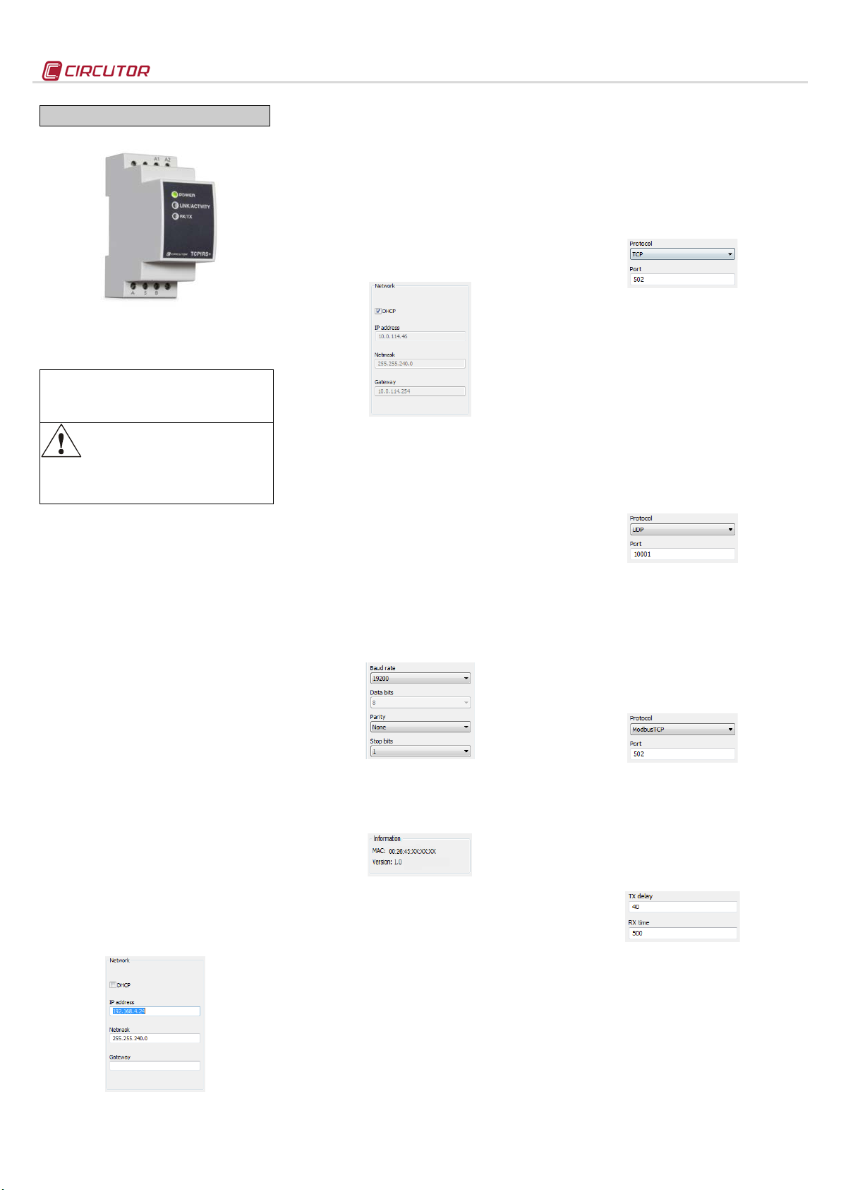
2.1.2.- Fixed IP assignment
Run IPSetup and select the TCP1RS+ c onverter. To assign the fixed IP address, enter the MAC address shown on the permanent side label attached to the device, the format of which is 00:26:45:XX:XX:XX.
In the IP Address field, enter the IP address being configured; do the same with the Netmask and the Gateway if necessary. After entering the device configuration, press “Configure” to send the configuration to the unit.
2.1.3.- DHCP IP assignment
To assign the DHC P name, activate this option by
clicking on the DHCP checkbox. Once the
configuration fields have been enabled, enter the
MAC address that can be seen on the permanent
side label attached to the device, the format of which
is 00:26:45:XX:XX:XX. In the Address, field, enter a
free temporary IP address, which is within the
working range of your computer.
2.2.- Configuration
Once the unit is connected to the Local Area
Network (LAN) and the IP address is configured or in
the DHCP mode, the remaining configuration can be
established in the IPSetup software console. When
the unit has been fully configured, the configuration
can be sent by clicking on “Configure”.
2.2.1.- Network protocol
The unit can be connected to the master communications system by means of three types of network protocols and to a configurable port (TCP, UDP or Modbus/TCP).
2.2.2.- Configuration of the Serial port
The communication parameters of the seri al bus are
fully configurable in terms of baud rate (1.2 bps to
115.2 kbps), data bits (7 or 8), parity (none, odd or
even) and stop bits (1 or 2). The data will be
configured by default to 8 by selecting the
Modbus/TCP communications protocol.
2.2.3.- Device information
When the unit is connected with IPSetup, the top part of the screen shows the firm ware version and the machine address of the device (the same address as that shown on the permanent side label).
2.2.4.- Save changes
Once any change has been made to the
aforementioned sections, the information must be
saved using the “Configure” option. If you wish to
return to the default configuration, select “Load
default”.
TCP1RS+
2.3.- Configuration of network protoc ols
2.3.1.- TCP Protocol
In the TCP/IP protocol stack, T CP is the intermediate
layer between the Internet protocol (IP) and the
application. In general, applications need reliable
communications. The IP layer offers an unreliable
datagram service (no confirmation), so the TCP adds
the functions required to offer a secure, error-free and
zero loss service for the communications between
two systems.
- Protocol: TCP Mode
- Port: Destination TCP Port number
2.3.2.- UDP Protocol
User Datagram Protocol (UDP) is a minimum
transport level message-oriented protocol that has
been documented in the RFC 768 of the IETF.
In the Internet protocol family, UDP provides a simple
interface between the network layer and the
application layer. UDP does not offer guarantees for
the delivery of its messages and the UDP origin does
not withhold the states of UDP messages sent to the
network. UDP only adds the multiplexing functionality
to the application and the verification sum of the
header and useful load. Any type of guarantees for
the transmission of information must be implemented
in higher layers.
- Protocol: UDP Mode
- Port: Destination UDP Port number
2.3.3.- Modbus/TCP Protocol
Modbus/TCP is a variation or extension of the
Modbus® protocol, which enables it to be used on the
TCP/IP transport layer. Therefore, Modbus/TCP can
be used throughout the Local Area Network or the
Internet. This was one of the objectives that
motivated its development (the specification of the
protocol was submitted to the IETF, Internet
Engineering Task Force).
- Protocol: Modbus/TCP Mode
- Port: Fixed port number 502
2.3.4.- Tx Delay Rx Time
The TCP1RS+ converter uses two communication parameters to control the Modbus frames on the RS485 bus.
- Tx Delay: additional delay of the RS serial bus
- Rx Time: maximum bus waiting time
M98253301-03-14A
Page 2
Power circuit:
- Humidity (no condensation) :
5 … 95%
LED symbols:
Mechanical features:
- Maximum operating height:
2,000 m
Network interface:
Serial interface:
- Stop bit
1 or 2
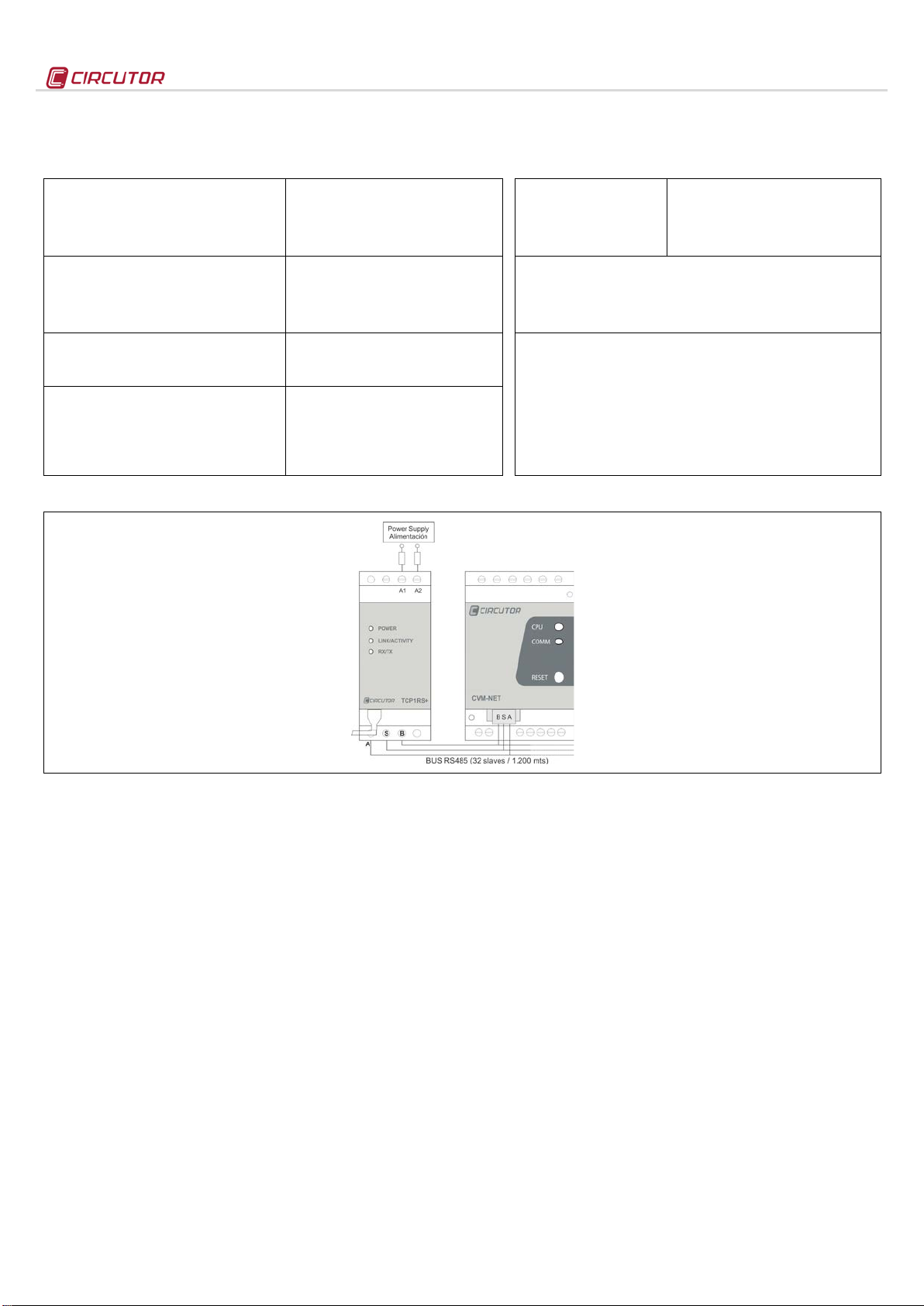
Figure 1. Standard connection of seri al uni t s
3.- TECHNICAL FEATURES
TCP1RS+
- Single-phase (A1 – A2) :
- Frequency:
- Maximum consumption:
- Working temperature:
- Case material:
- Unit protection degree:
- Dimensions (mm):
- Weight:
- Type:
- Connector:
- Network Protocols - Accesses:
- Type:
- Transmission speed (configurable):
- Data bits:
- Parity:
4.- CONNECTIONS
230 Vac ± 15%
47…63 Hz
8 VA
-10 … +60 ºC
UL94 - V0 self-extinguishing plastic
IP 20
35.4 x 73 x 84.68 mm (2 modules)
120 g
Ethernet 10BaseT / 100BaseTX self-detecting
RJ45
TCP / UDP / Modbus
RS-485 three-wires (A/S/B) (RX/GND/TX)
1200, 2400, 4800, 9600,19200, 34800, 57600,
115200 baud rate
7, 8
No parity, odd, even
- Flashing power LED
- Flashing RX/TX
- LINK/ACTIVITY
Standards:
IEC 60664, VDE 0110, UL 94, EN61010-1, EN55011, EN 61000-4-2, EN 61000-4-3,
61000-4-11, EN 61000-6-4, EN 61000-6-2, EN 61000-6-1, EN 61000-6-3, EN 61000-4-5,
CE
Safety:
Installation category: Category III / EN61010 double-i nsulated electric shock protecti on
class II. The unit must be c onnected to a power circui t protected with type gl fuses, i n
compliance wi th IEC 269, or t ype M, with values fr om 0.5 to 1A. It must be fi tted with a
circuit breaker switch or equi valent device i n order to be able to disc onnect the unit from
the power supply. The power supply cable must have a minimum cross-section of 1 mm
If the unit is not operat ed according to the manufacturer's specifications, it s guaranteed
degree of protection may be compromised.
Powered unit and CPU activity
RS-485 frame delivery and reception activity
Flashing: Activity in the Ethernet bus
Green: Speed 10/100 Mb/s
2
.
5.- TECHNICAL SERVICE
If you have any doubts about the operation of the unit or suspect any malfunction, contact our service staff at CIRCUTOR, SA
CIRCUTOR, SA - Technical Assistance Service
Vial Sant Jordi, s/n
08232 – Viladecavalls (Barcelona), SPAIN
Tel.: 902 449 459 (Spain)
Tel.: (+34) 93 745 29 00 (Outside Spain)
email: sat@circutor.es
M98253301-03-14A
 Loading...