

Page 1
OVERLOAD PROTECTION RECLOSING
EQUIPMENT
DIN SERIES RAIL
RRM-P / RRM-C + MT
INTRODUCTION
1. .
The RRM range of relays allows the control, remote
signalling and control of the associated motorized circuit
breaker (MT SERIES)
The functions of the RRM relay are
Control of the motorized overload/short circuit
protection
reconnectable)
-
- .
The self reclosing equipment for DIN rail consists of
:
Self reclosing
- .
Remote disconnection/connection (not
-
Signalling:
On site using LEDs
- .
Remote signalling using relay, of the reclosure
-
seal in model RRM-P
RS485 Communications in model RRM-C
- .
Remote control of the automatic switch
Motorised, MT type overload/short circuit
-
protectors (2 or 4 pole)
RRM control relay
- .
.
.
.
:
.
:
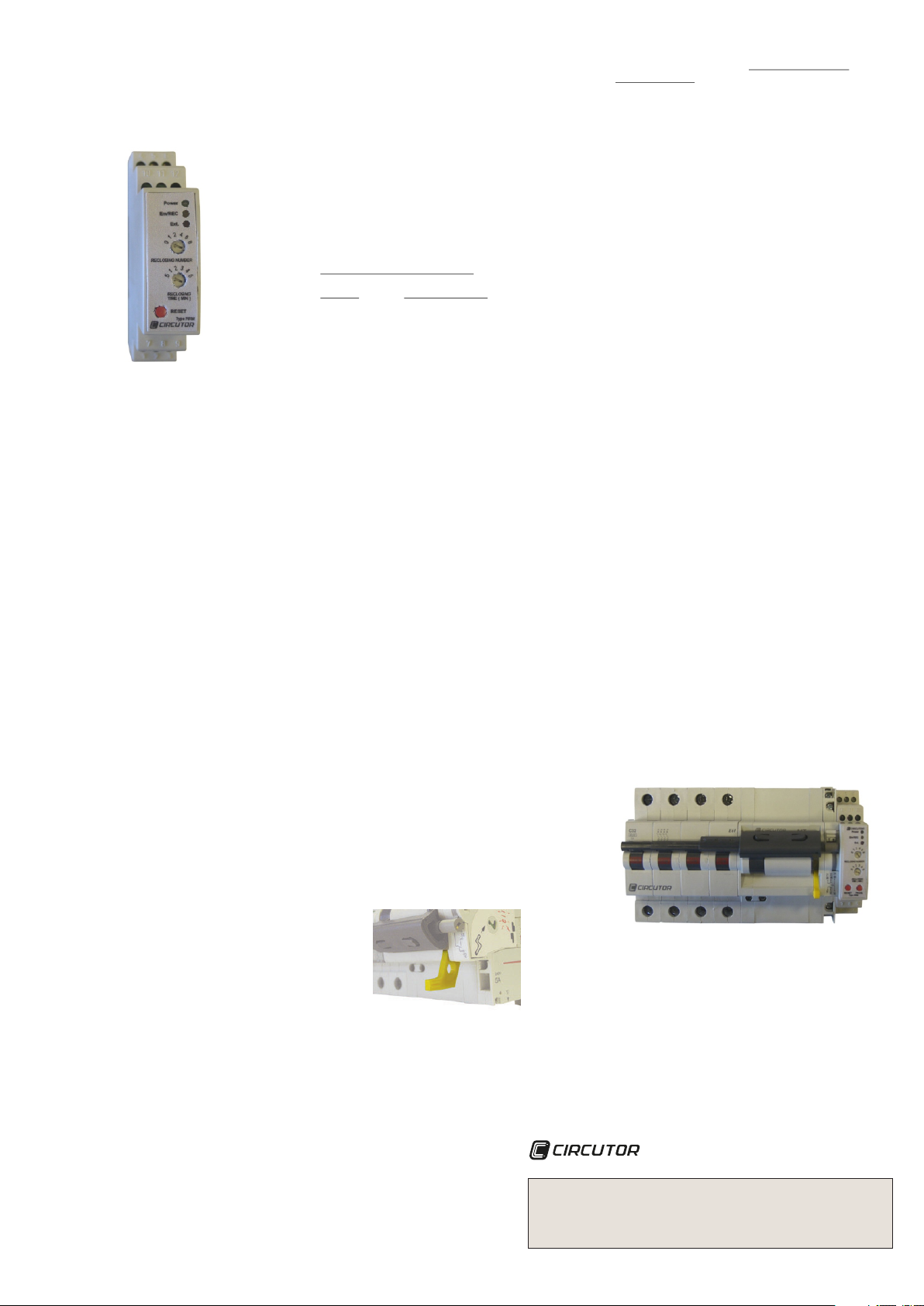
2.- RRM
Button description
Reset
Prog.
Switch description
Nº Rec.
Time Rec.
On site signalling using LEDs
Display LED description
Power
Em/REC
Ext.
Remote signalling (relay). Terminals No. 10, 11, 12.
Model RRM-P only.
Indication of the status of self reclosing
-
-
RS485
on model RRM-C only
( )
The RS485 port can communicate:
-
-
DESCRIPTION.
Rearm of the sealed relay and/or returning to
zero of the internal reclosure counters
Only on model RRM-C. Pressing sends
voltage to the relay, it is started with the
address no. 1 in the RS485 system.
Select the number of reclosures: 0, 1, 2, 4, 6,
8. Position zero cancels the motorised circuit
breaker reclosures
Select the time between reclosures in units of
minutes: 0.5, 1, 2, 3, 4, 5
Indicates that the relay is being supplied and
the overload/short circuit breaker protection
is not tripped. Green LED.
Overload/short circuit breaker on OFF as
default
.
LED constantly on indicates that the relay
reclosure is sealed
LED flashing indicates that the relay is in the
process of reclosing
Overload/short circuit breaker on OFF
from an external command Red LED
Contact 10-11 closed switch ON.
Contact 10-12 closed switch OFF and reclosing
electronically sealed
Communications
The status of the circuit breaker (ON, OFFext., OFFrec,
OFF sealed
Remote control. Disconnection and connection of the
circuit breaker
).
.
.
.
. Yellow LED.
. .
.
.
:
.
OPERATION
3.- .
Features of the RRM as an overload/short circuit
reclosure device
No. of reclosures: Programmable (0, 1, 2, 4, 6, 8
- ).
Time between reclosures
- :
Programmable (0.5, 1, 2, 3, 4, 5 minutes
).
ime to return to zero: 30 minutes
- T .
The RRM relay is associated with the MT series,
motorised overload/short circuit breakers.
ctions of the RRM relay
Fun
Self reclosing of the motorised overload/short circuit
breaker
Setting the reclosure parameters
- :
- .
- T .
Remote control. The disconnection or reclosure of
-
the automatic switch may be forced using a potential
free input or using a 230 V AC. voltage. (When this
contact is closed, the switch cannot be reclosed).
When the relay reclosure is already sealed the remote
control doesn´t act
RS485 communications (on model RRM-C
- ):
- (ON, OFF).
- OFFext, OFF enc.
-
-
-
- .
- .
-
19200 baud, 8, N, 1
:
.
No. of reclosures.
ime between reclosures
.
Reads the status of the protection
Status of the reclosure
Remote reclosure and disconnection (no
reclosable
Setting the peripheral number by
communications
Key for default setting the no. of the peripheral
(no. 1
MODBUS (RTU) protocol communications
Signalling blocked
Communication parameters :
).
.
).
GENERAL FEATURES.
4.-
operations
relay
:
: - 230 V AC.
DC. ± 20 % without polarity, not
galvanically insulated
: -10º to +50ºC.
6
.
4.1 RRM
Auxiliary voltage
Two versions
- 12 V
Operating temperature
Motor control contact:
Nominal voltage : 250 V AC.
nominal: 1 A AC.
I
gaff for 20 ms : 10 A.
I
Insulating voltage : 2500 V AC.
Signalling contact:
Nominal voltage: 24 V DC.
nominal : 1 A DC.
I
No. : 3·10
MT motorized circuit breaker
4.2
In the overload/short circuit protection (MT) there is
2p or 4p overload/short circuit protection.
-Motor (mechanical sealing lever)
-- .
Status signalling auxiliary contact
-- .
The yellow lever on the MT must always be lowered
when handling the equipment in order to avoid
uncontrolled connections. (See
Fig. 1)
Fig. 1
:
Technical service
CIRCUTOR SAT: 902 449 459(SPAIN) / (+34) 937 452 919 (out of Spain)
Vial Sant Jordi s/n
08232 - Viladecavalls (Barcelona)
Tel. (+34) 937 452 900 - Fax (+34) 937 452 914
e-mail: sat@circutor.es
- RRM-P / RRM-C + MT
M98205101-03-15A
Page 2
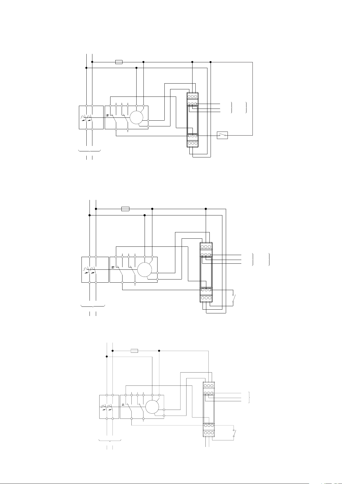
5.- CONNECTION DIAGRAM MT- E62/E64 SERIES
5.1.- RRM-C/ RRM-P + MT-E62/E64
SYSTEM
N L
EXTERNAL POWER SUPPLY CONNECTION DIAGRAM
F1
5.2.- RRM-C/ RRM-P + MT-E62/E64
1
2
12 9614 98
3
H H
4
11 95
N L
LOAD
SYSTEM
N L
F1
1 3 12 9614 98
H H
4
2
11 95
I
O
654
N
L
Off
O
M
On
I
MT
121110
8
9
7
231
LN
INTERNAL POWER SUPPLY CONNECTION DIAGRAM
I
O
654
121110
8
7
231
MT
M
N
L
Off
O
On
I
LN
ACCORDING TO MODEL:
RRM-C
Rs485 Bus
External
Trip
9
12 = GND
11 = B
10 = A
RRM-P
SEALED RELAY
12 = COM
11 = NC
10 = NO
ACCORDING TO MODEL:
RRM-C
Rs485 Bus
12 = GND
11 = B
10 = A
External
Trip
RRM-P
SEALED RELAY
12 = COM
11 = NC
10 = NO
N L
LOAD
5.3.- RRM-P 12 V.d.c + MT-E62/E64
SYSTEM
N L
LN
LOAD
F1
I
O
5
4
6
11
10
31
1412
H
N
9896
L
Off
O
M
H
MT
On
I
12
SEALED RELAY
NO
NC
COM
951142
8
9
3
172
Auxiliary voltage
12V DC. Without polarity
External
Trip
M98205101-03-15A
 Loading...