

Page 1
Earth leakage relay
RGU-2
INSTRUCTION MANUAL
(M98251301-03-13B)
Page 2

RGU-2 Earth Leakage Relay
2
Instruction Manual
Page 3
RGU-2 Earth Leakage Relay
SAFETY PRECAUTIONS
Follow the warnings described in this manual with the symbols shown below.
DANGER
Warns of a risk, which could result in personal injury or material damage.
ATTENTION
Indicates that special attention should be paid to a speci c point.
If you must handle the unit for its installation, start-up or maintenance, the following
should be taken into consideration:
Incorrect handling or installation of the unit may result in injury to personnel as well as damage
to the unit. In particular, handling with voltages applied may result in electric shock, which may
cause death or serious injury to personnel. Defective installation or maintenance may also
lead to the risk of re.
Read the manual carefully prior to connecting the unit. Follow all installation and maintenance
instructions throughout the unit’s working life. Pay special attention to the installation standards of the National Electrical Code.
Refer to the instruction manual before using the unit
In this manual, if the instructions marked with this symbol are not respected or carried out correctly, it can
result in injury or damage to the unit and /or installations.
CIRCUTOR, SA reserves the right to modify features or the product manual without prior noti cation.
DISCLAIMER
CIRCUTOR, SA reserves the right to make modi cations to the device or the unit speci ca-
tions set out in this instruction manual without prior notice.
CIRCUTOR, SA on its web site, supplies its customers with the latest versions of the device
speci cations and the most updated manuals.
www.circutor.com
Instruction Manual
3
Page 4

RGU-2 Earth Leakage Relay
CONTENTS
SAFETY PRECAUTIONS �����������������������������������������������������������������������������������������������������3
DISCLAIMER ������������������������������������������������������������������������������������������������������������������������ 3
CONTENTS ��������������������������������������������������������������������������������������������������������������������������� 4
REVISION LOG ��������������������������������������������������������������������������������������������������������������������� 5
1�- VERIFICATION UPON RECEPTION ������������������������������������������������������������������������������� 6
2�- PRODUCT DESCRIPTION ���������������������������������������������������������������������������������������������� 6
3�- UNIT INSTALLATION ������������������������������������������������������������������������������������������������������ 7
3�1�- PRIOR RECOMMENDATIONS �������������������������������������������������������������������������������� 7
3�2�- INSTALLATION �������������������������������������������������������������������������������������������������������� 8
3�3�- UNIT TERMINALS ��������������������������������������������������������������������������������������������������� 8
3�4�- CONNECTION DIAGRAM ��������������������������������������������������������������������������������������� 9
3�4�1� AS A PROTECTION ELEMENT (MRCD) ����������������������������������������������������� 9
3�4�2� AS A MONITOR (RCM) ������������������������������������������������������������������������������� 10
4�- START-UP ��������������������������������������������������������������������������������������������������������������������� 10
4�1�- DEFAULT CONFIGURATION �������������������������������������������������������������������������������� 10
4�2�- BASIC SETUP ������������������������������������������������������������������������������������������������������� 11
5�- OPERATION ����������������������������������������������������������������������������������������������������������������� 11
5�1�- KEYBOARD FUNCTIONS ������������������������������������������������������������������������������������� 12
5�2�- DISPLAY ����������������������������������������������������������������������������������������������������������������� 12
5�3�- LED INDICATORS ��������������������������������������������������������������������������������������������������14
5�4�- INPUTS ������������������������������������������������������������������������������������������������������������������� 14
5�5�- OUTPUTS ��������������������������������������������������������������������������������������������������������������� 15
5�5�1� TRIP RELAY, TRIP �������������������������������������������������������������������������������������� 15
5�5�2� AUXILIARY RELAY, AUX���������������������������������������������������������������������������� 15
5�6�- PROGRAMMING ���������������������������������������������������������������������������������������������������� 16
5�6�1 TRIP CURRENT IΔn and TRIP DELAY TIME td ����������������������������������������������16
5�6�2 PROGRAMMING THE AUXILIARY RELAY, AUX ��������������������������������������� 17
5�6�3 FREQUENCY AND STATUS OF THE OUTPUT RELAY CONTACTS �������� 18
5�6�4 LOCKING THE KEYBOARD ����������������������������������������������������������������������� 19
5�7�- TRIP EVENTS ��������������������������������������������������������������������������������������������������������20
5�7�1� EARTH LEAKAGE CURRENT INTENSITY TRIP �������������������������������������� 20
5�7�2� LOCAL / EXTERNAL TEST TRIP��������������������������������������������������������������� 21
5�7�3� UNDERVOLTAGE / POSITIVE SAFETY PROTECTION TRIP ������������������ 21
5�7�4� INPUT SENSOR ERROR TRIP ������������������������������������������������������������������ 21
5�8�- RECLOSING SYSTEM ������������������������������������������������������������������������������������������� 22
5�8�1� “MANUAL” RECLOSING SYSTEM WITH THE RESET KEY ������������������� 22
5�8�2� RECLOSING SYSTEM WITH THE EXTERNAL TEST/RESET INPUT ������ 22
6�- TECHNICAL FEATURES ����������������������������������������������������������������������������������������������� 23
6�1�- DIMENSIONS ��������������������������������������������������������������������������������������������������������� 24
7�- MAINTENANCE AND TECHNICAL SERVICE �������������������������������������������������������������� 25
8�- WARRANTY ������������������������������������������������������������������������������������������������������������������� 25
9�- CE CERTIFICATE ���������������������������������������������������������������������������������������������������������� 26
APPENDIX A: TRIP CURVES ��������������������������������������������������������������������������������������������� 27
4
Instruction Manual
Page 5
RGU-2 Earth Leakage Relay
REVISION LOG
Table 1: Revision log�
Date Revision Description
10/13 M98251301-03-13A Initial Version
11/13 M98251301-03-13B Modied Figure 1
Instruction Manual
5
Page 6
RGU-2 Earth Leakage Relay
1�- VERIFICATION UPON RECEPTION
Check the following points when you receive the unit:
a) The unit meets the specications described in your order.
b) The unit has not suffered any damage during transport.
c) Perform an external visual inspection of the unit prior to switching it on.
d) Check that it has been delivered with the following:
- a seal to lock the programming button.
- installation guide.
If any problem is noticed upon reception, immediately contact the transport
company and/or CIRCUTOR's after-sales service.
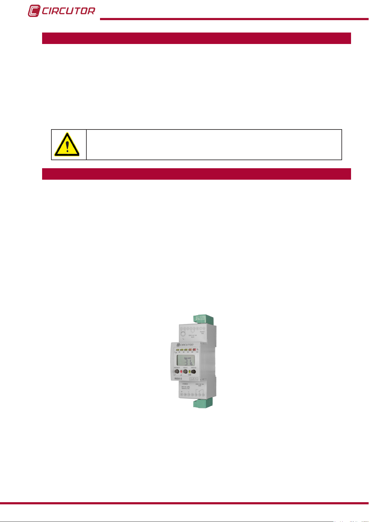
2�- PRODUCT DESCRIPTION
RGU-2 is a protection and/or measurement relay (MRCD/RCM). It is a smart earth leakage
protection system composed of the following elements:
- A detecting element or sensor,
- A relay,
- A circuit breaker,
The unit is fully programmable. It is supplied with the following:
- 3 Keys, used to TEST/RESET and program the unit.
- 2 operation LEDs that display the unit's status.
- LCD Display that displays messages and operation values.
- An LED Bar that displays qualitative level of leakage information.
- Plug-in terminal strips.
The unit is characterised by its reduced dimensions (2 modules mounted on a DIN rail).
It has been designed for single-phase, three-phase or three-phase with neutral low voltage
electrical installations. It is suitable for all neutral rates (VT, TN, IT), either as the main protection
element (MRCD) or for complementary purposes (RCM).
In the case of VT/TN-S systems, it can be used as a MRCD (IEC 60947-2) or a RCM (IEC
62020). It can only be installed as an RCM in other systems.
6
Instruction Manual
Page 7
RGU-2 Earth Leakage Relay
3�- UNIT INSTALLATION
3.1.- PRIOR RECOMMENDATIONS
In order to use the unit safely, it is critical that individuals who handle it follow the
safety measures set out in the standards of the country where it is being used,
use the personal protection unit necessary, and pay attention to the various warnings indicated in this instruction manual.
The RGU-2 unit must be installed by authorised and qualied staff.
The power supply plug must be disconnected and measuring systems switched off before handling, altering the connections or replacing the unit. It is dangerous to handle the unit while it is
powered.
Also, it is critical to keep the cables in perfect condition in order to avoid accidents, personal
injury and damage to installations.
The manufacturer of the unit is not responsible for any damages resulting from failure by the
user or installer to heed the warnings and/or recommendations set out in this manual, nor for
damages resulting from the use of non-original products or accessories or those made by other
manufacturers.
In the event an anomaly or malfunction is detected in the unit, refrain from using it to make any
measurements.
Inspect the work area before making any measurements. Do not take measurements in dangerous areas or where there is a risk of explosion.
Disconnect the unit from the power supply (unit and measuring system power
supply) before maintaining, repairing or handling the unit's connections.
Please contact the after-sales service if you suspect that there is an operational
fault in the unit.
Instruction Manual
7
Page 8
RGU-2 Earth Leakage Relay
3.2.- INSTALLATION
The unit is installed on a DIN rail.
All active conductors that supply the loads or the part of the installation where the earth leakage protection with this unit is required must pass through the sensor associated with the unit.
The unit must be mounted inside an electric panel.
Likewise, it must be connected to a fuse-protected power circuit, in accordance with its power
supply range and consumption. In turn, the power circuit must be tted with a circuit breaker
switch or an equivalent device, in order to be able to disconnect the unit from the power supply
mains.
Note: The connection diagram suggests a cable section of 1- 1.5 mm.
Recommended torque 0.5-0.6 Nm.
Terminals, opening covers or removing elements can expose parts that are hazardous to the touch while the unit is powered
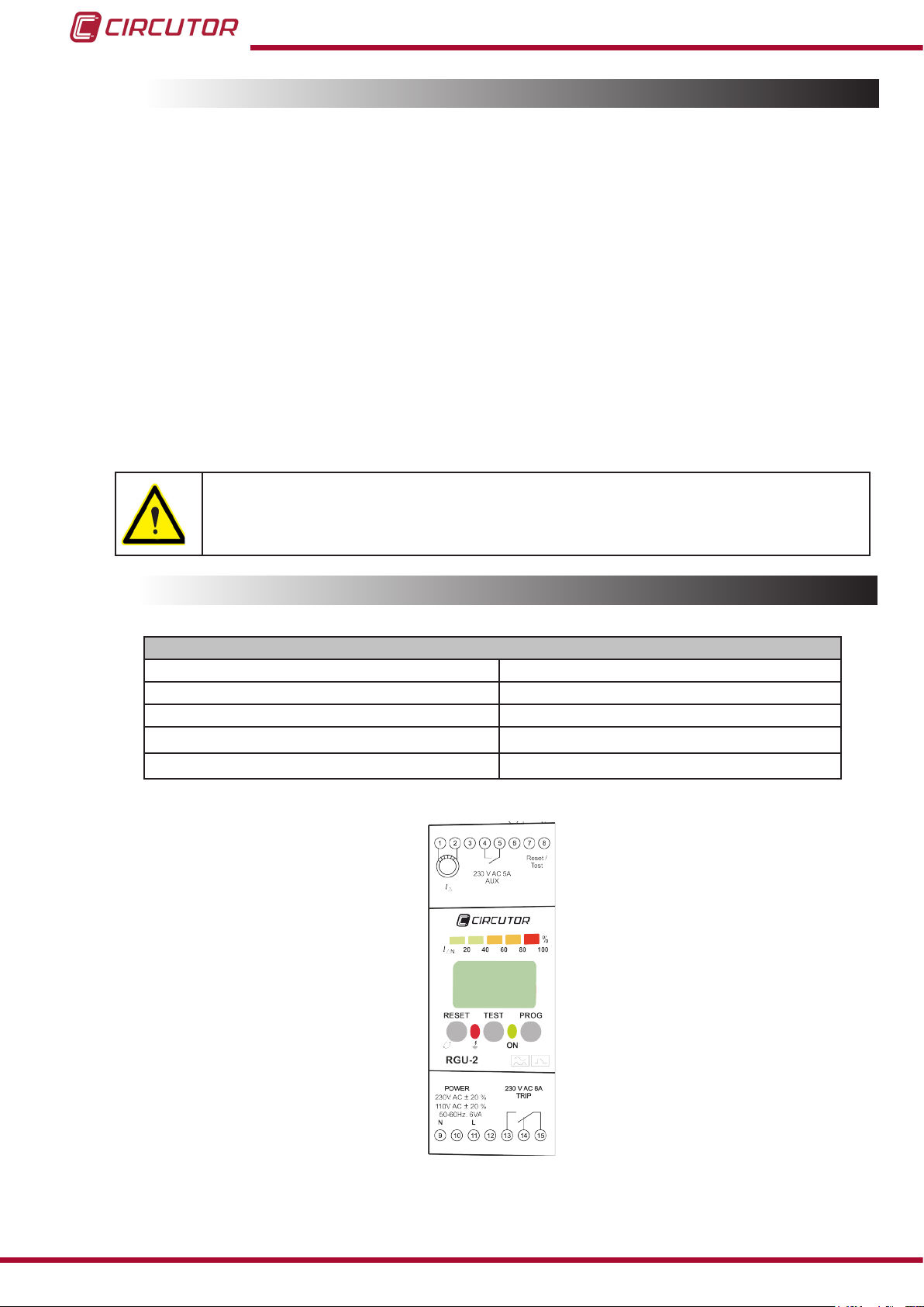
3.3.- UNIT TERMINALS
Table 2: Unit terminals�
Unit terminals
1, 2 : External current sensor input. 8: External Test/Reset input with button.
3, 6, 10, 12: Not used 9, 11: Auxiliary Power Supply
4: Prealarm/Fault relay output: NO Contact 13: Trip relay output: NO Contact
5: Prealarm/Fault relay output: COM Contact 14: Trip relay output: NC Contact
7: External Test/Reset input with button. 15: Trip relay output: COM Contact
Figure 1:Unit terminals�
8
Instruction Manual
Page 9
RGU-2 Earth Leakage Relay
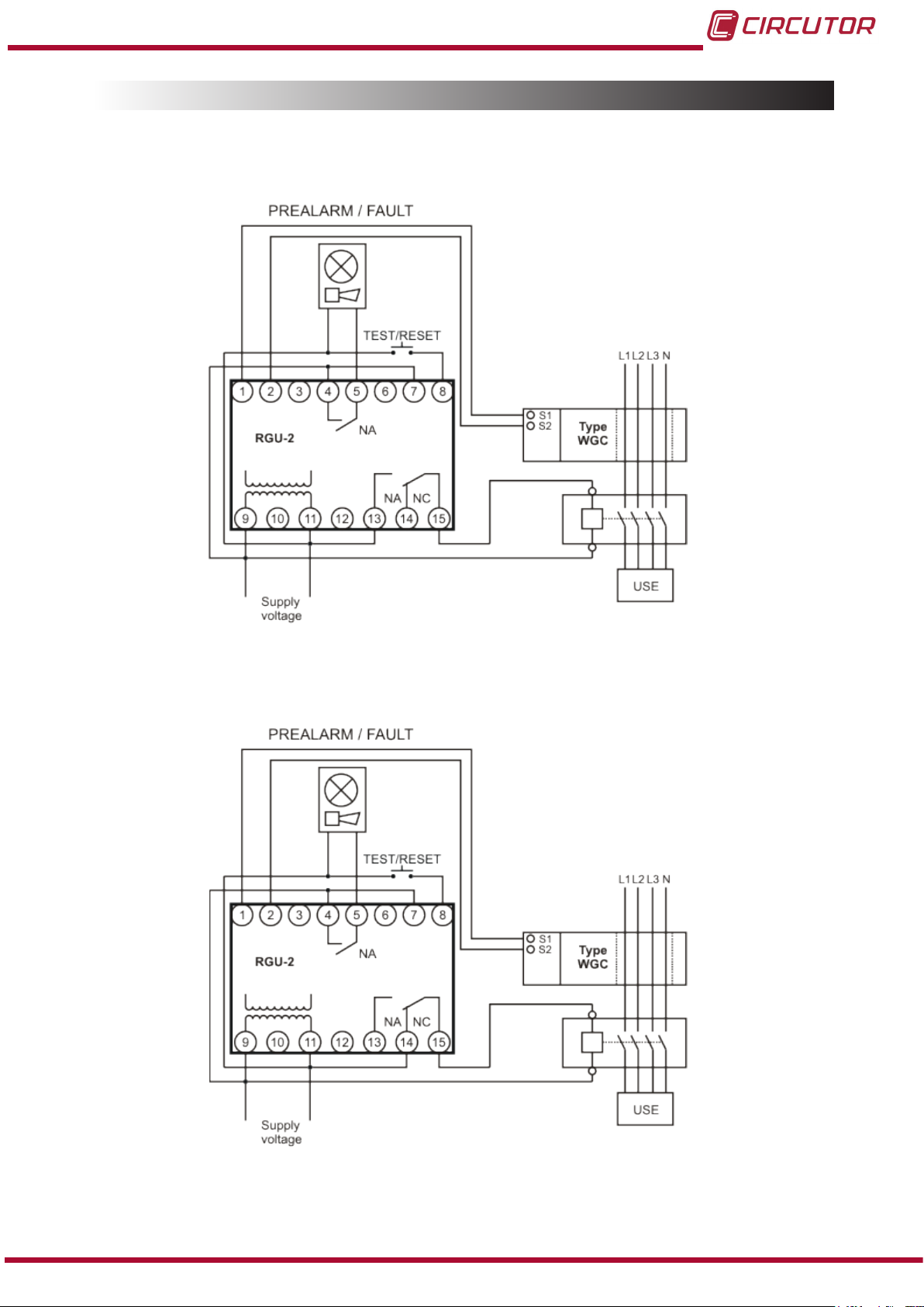
3.4.- CONNECTION DIAGRAM
3�4�1� AS A PROTECTION ELEMENT (MRCD)
A�- SHUNT COIL TRIP (Manual reclosing system with RESET)
Figure 2: Connection diagram of the unit as a protection element: shunt coil trip�
B�- UNDERVOLTAGE COIL TRIP (Manual reclosing system with RESET)
Figure 3:Connection diagram of the unit as a protection element: undervoltage coil trip�
Instruction Manual
9
Page 10

3�4�2� AS A MONITOR (RCM)
RGU-2 Earth Leakage Relay
Figure 4:Connection diagram of the unit as a monitor�
4�- START-UP
4.1.- DEFAULT CONFIGURATION
When the unit is powered with auxiliary voltage, the ON LED is lit green and the LCD is backlit
green.
The name of the model, rmware version and a xed screen that shows the conditions in which
the earth leakage protection is characterised will be displayed.
This screen is displayed by default when there are no external actions (Figure 5).
10
Figure 5: Earth leakage protection screen
The unit is supplied with the following default factory conguration:
- Trip current scale (IΔn) : 30mA
- Trip time scale (td) :Instantaneous curve (IN)
- Frequency: 50 Hz
- Auxiliary relay function: Fault relay
- Polarity of the trip relay: Standard
- Polarity of the auxiliary relay: Standard
Instruction Manual
Page 11

RGU-2 Earth Leakage Relay
In case a level of leakage has been detected, the LCD will show the earth leakage symbol,
(Figure 6)�
Figure 6: Earth leakage protection with leakage screen�
Finally, the following screen will be displayed when the AUX relay has been congured as a
prealarm, (Figure 7).
Figure 7:Earth leakage protection with prealarm screen�
4.2.- BASIC SETUP
Once the unit has been connected, it must be programmed in accordance with the installation's
features.
The following basic parameters can be programmed:
- Adjust the trip current.
- Adjust the trip delay time.
- Select the frequency of the installation to be supervised.
5�- OPERATION
The RGU-2 unit helps control the electrical insulation level of an installation by controlling the
intensity of the leakage current.
Intelligent block Actuator blockSensor block
Inputs
RGU-2
Outputs
An external sensor detects and measures the earth leakage current. Circutor offers the following unit protection models in its current range of sensors: WG/WGS/WGC/TP-WG.
Instruction Manual
11
Page 12

RGU-2 Earth Leakage Relay
When the instantaneous leakage current has been measured, the RGU-2 unit will operate in
accordance with the programmed parameters:
- Trip current (IΔn)
- Trip delay time (td)
As a result, the status of the device's output contacts will be changed. The output of this contact
will be used as follows, depending on the nal application type:
- Earth leakage protection (IEC61008-1), the circuit breakers are activated.
- Earth leakage monitoring (IEC62020), alarm alerts, sound and/or visual devices.
5.1.- KEYBOARD FUNCTIONS
The unit has 3 keys: RESET, TEST and PROG.
PROG Key
Pressing this key displays the different screens and opens the programming mode (hold down
the key for 2 seconds) to adjust the different programming parameters.
This key is sealable; it is supplied with a small hole where the conguration can be physically
disabled.
TEST Key
Press the TEST key to check the connection status of the sensor element and force the tripping
of the unit.
RESET key
Locally rearms the electronic relay, resetting the status of the output contacts to the normal
standby status.
If the unit is in standby status, it will scroll down the model and version (5s) on the green
LCD.
5.2.- DISPLAY
The unit has a green/red backlit LCD. The background will be green under normal conditions.
The display will be red in case of events that cause an action (protection trigger or circuit
breaker being tripped).
12
Figure 8:Display
Instruction Manual
Page 13

RGU-2 Earth Leakage Relay
The following are shown on the display by default:
- IΔn, Adjusted trip current and associated units.
- td, Delay time of the adjusted trip and associated units.
- Prealarm symbol (when active).
The unit has different screens that can be set as the unit's display:
Earth leakage protection screen (Figure 9)
Figure 9:Earth leakage protection screen
Instantaneous current screen (Figure 10)
Figure 10:Instantaneous current screen
The trip current will be displayed when the protection element has been tripped (Figure 11):
Figure 11: Trip current screen (Example: 45mA trip current)
Floating screens can also be displayed; they will be shown during 5 seconds and then return to
the xed active screen, such as:
AUX relay prealarm screen (Figure 12).
Instruction Manual
Figure 12:Prealarm screen�
13
Page 14

AUX relay fault screen (Figure 13)�
Figure 13:Fault relay screen�
5.3.- LED INDICATORS
The unit has the following LEDs:
LED ON
Green LED, indicates that the unit is voltage-fed.
The LED ashes when problems have been detected in the sensor.
RGU-2 Earth Leakage Relay
LEAKAGE LED
Red LED indicates that the protection element has been tripped as a result of a residual
current intensity value that is higher than the current threshold required to trip the protection
element.
LED Bar
LED Bar indicates the leakage current level of the installation. The current levels are displayed
as a %, in accordance with the selected trip scale:
20% - 40% - 60% green,
80% yellow,
100% red.
5.4.- INPUTS
The unit has two inputs:
External current sensor input (terminals 1 and 2 in Figure 1). With this input the unit checks
every 5 seconds whether the connection with the external sensor is correct by means of an
inductive test.
14
External test input with button (terminals 7 and 8 in Figure 1).
Input activated by level. When voltage is applied, this forces the tripping of the unit; when it is
no longer applied the unit returns to the previous state.
The keyboard reset function will be disabled when this input is active.
Instruction Manual
Page 15

RGU-2 Earth Leakage Relay
5.5.- OUTPUTS
The unit has two independent output relays:
5�5�1� TRIP RELAY, TRIP
Switched contact relay (terminals 13, 14 and 15 in Figure 1)
The unit can be programmed to modify the logical status of the contact (refer to section 5.6.3)
from the standard NC/NO status to the NO/NC positive safety status.
The positive safety status is shown on all screens that refer to the TRIP, with the + sign (Figure
14). The prealarm/fault screen will not be affected by this.
Figure 14: Positive safety status screen
5�5�2� AUXILIARY RELAY, AUX
Simple contact relay (terminals 4 and 5, and Figure 1) non-interlocking. Its operation can be
programmed as a prealarm or fault relay (refer to section 5.6.2 )
Prealarm (ALAR), activated when the IΔ > 0.5•IΔn, in 200 milliseconds. The logical sta-
tus of the contact (refer to section 5.6.3) can be changed from the NO standard status to the
NC positive safety status.
The Fault relay (AUXF), is activated to notify fault events in the unit, such as:
undervoltages (the voltage is below the unit's operation voltage - the unit turns off below this
voltage) or faults in the external sensor.
In this case, the relay operates with the positive safety status.
Positive safety is shown with the + sign (only in the screens that refer to the AUX relay).
Instruction Manual
Figure 15:Screens with a positive safety status�
15
Page 16

RGU-2 Earth Leakage Relay
5.6.- PROGRAMMING
5�6�1 TRIP CURRENT IΔn and TRIP DELAY TIME td
The earth leakage protection screen must be displayed to program the current and delay time
of the trip. Hold down the PROG key for 2 seconds.
PROG
Trip delay time, td
The current value will start ashing. Press the RESET key gradually to
browse all programming values (Tabla 3).
Accept with the PROG key.
PROG
Trip current, td
The current value will start ashing. Press the RESET key gradually to
browse all programming values (Tabla 3).
Accept with the PROG key.
PROG
If changes have been applied, SAVE will be displayed for 3 sec-
onds and the unit will exit the programming screens.
If changes have not been applied, EXIT will be displayed for 3 sec-
onds and the unit will exit the programming screens.
Note: If you reach the last value of the Trip current to be congured and you do not press the
PROG key to accept the changes, the unit will exit the programming screen after 5 seconds
and the changes will not be saved.
Table 3:Relationship of Currents and Trip Times to be programmed�
Trip current IΔn Trip time td
30mA IN ( Instantaneous )
0.1A SE (Selective)
0.3A 0.1s
0.5A 0.2s
1A 0.3s
2A 0.5s
3A 0.8s
5A 1s
2s
3s
5s
(1)
The trip curves are shown in Appendix A
(1)
(1)
16
Instruction Manual
Page 17

RGU-2 Earth Leakage Relay
5�6�2 PROGRAMMING THE AUXILIARY RELAY, AUX
Open the auxiliary output screen and hold down the RESET key for 2 seconds to program the
operation of the auxiliary relay.
Prealarm (ALAR)
This is activated when IΔ > 0.5•IΔn, in 200 milliseconds.
RESET
Fault relay (AUXF)
Shows fault events in the unit, such as undervoltages or faults in the
external sensor.
Operates in the positive safety status.
Instruction Manual
17
Page 18

RGU-2 Earth Leakage Relay
5�6�3 FREQUENCY AND STATUS OF THE OUTPUT RELAY CONTACTS
To program the frequency and status of the output relay contacts, TRIP and AUX, open the
instantaneous current screen and hold down the PROG key for 2 seconds.
PROG
Frequency (50Hz by default)
PROG
Select the frequency: 50Hz or 60Hz.
Accept with the PROG key.
RESET
RESETRESET
RESET
PROG
PROG
RESETRESET
RESET
Status of the TRIP relay contact
(STD, by default)
STD: Standard NC/NO status
POS: NO/NC positive safety status
When this option is activated, the + sign
will appear on all screens that refer to the
TRIP relay.
Accept with the PROG key.
Status of the AUX relay contact
(STD, by default)
STD: Standard NO status.
POS: NC positive safety status.
When this option is activated, the + sign
will appear on all screens that refer to the
AUX relay.
18
Accept with the PROG key.
If changes have been applied, SAVE will be displayed for 3 seconds
and the unit will exit the programming screens.
If changes have not been applied or the keyboard has been inactive
during 5 seconds, EXIT will be displayed for 3 seconds and the unit will
exit the programming screens.
Instruction Manual
Page 19

RGU-2 Earth Leakage Relay
5�6�4 LOCKING THE KEYBOARD
The unit has a series of devices that can be used to disable the programming operations (sealable PROG button). However, the PROG key can be locked with the unit's software by holding
down the RESET and PROG keys for 2 seconds.
PROG
BLON (N appears ashing)
Unlocked keyboard.
RESET
RESET
BLOY (Y appears ashing)
Locked keyboard.
Accept with the PROG key.
If changes have been applied, SAVE will be displayed for 3 seconds
and the unit will exit the programming screens.
If changes have not been applied or the keyboard has been inactive
during 5 seconds, EXIT will be displayed for 3 seconds and the unit will
exit the programming screens.
When the PROG key is locked, a oating message will appear on the display to show that it is
protected if it is pressed.
Instruction Manual
19
Page 20

RGU-2 Earth Leakage Relay
5.7.- TRIP EVENTS
When a circuit breaker has been activated, the LEDs, output contacts and display will indicate
the cause that generated this situation.
5�7�1� EARTH LEAKAGE CURRENT INTENSITY TRIP
LED
ON LED, off.
LEAKAGE LED, xed.
OUTPUT RELAYS
The TRIP relay (terminals 13,14,15) changes its status, IΔ >0,85•IΔn, in accord
ance with the programmed times
The AUX relay (terminals 4,5) only changes its status if it has been congured
as a pre-alarm
DISPLAY
Fixed red screen that shows the leakage with the earth leakage symbol
(Figure 16).
Figure 16:Leakage screen
Prealarm symbol when this function has been activated (Figure 17).
Figure 17:Leakage with prealarm screen
Note : Press the PROG key to modify the current and trip time. ( refer to sec-
tion 5.6.1)
If the value is off the scale (> 5•IΔn), OVR and the pre-alarm symbol will be dis
played (Figure 18).
20
Figure 18: Off the scale screen
Instruction Manual
Page 21

RGU-2 Earth Leakage Relay
5�7�2� LOCAL / EXTERNAL TEST TRIP
LED
ON LED, off.
LEAKAGE LED, xed.
OUTPUT RELAYS
The TRIP relay (terminals 13,14,15) changes its status.
The AUX relay (terminals 4,5), only changes its status if it has been congured
as a prealarm
DISPLAY
Red screen that shows that the cause has been as a result of the TEST
(Figure 20),
Figure 19: Test screen
5�7�3� UNDERVOLTAGE / POSITIVE SAFETY PROTECTION TRIP
OUTPUT RELAYS
The AUX relay (terminals 4,5), only changes its status if it has been congured
in the fault mode with positive safety. When the power supply voltage is below
the minimum operating voltage of the unit, the relay output will change its status
to standby.
5�7�4� INPUT SENSOR ERROR TRIP
LED
ON LED, ashing
LEAKAGE LED, xed.
OUTPUT RELAYS
The TRIP relay (terminals 13,14,15) changes its status.
The AUX relay (terminals 4,5), only changes its status if it has been congured
in the fault mode.
DISPLAY
Red screen that shows that the cause has been an inductor error in the
input sensor (Figure 21).
Instruction Manual
Figure 20: Input sensor error screen
21
Page 22

RGU-2 Earth Leakage Relay
5.8.- RECLOSING SYSTEM
The reclosing system varies after a leakage or test trip, in accordance with the unit's connection
diagram.
5�8�1� “MANUAL” RECLOSING SYSTEM WITH THE RESET KEY
The unit's power supply must be connected before the circuit breaker.
1� In the event of tripping, the unit is set to tripping conditions and the circuit breaker
(MCB/MCCB with coil) is set to OFF.
2� The unit returns to the normal operating conditions after the RESET key has been pressed.
3� Finally, the ON circuit breaker is activated manually.
NOTE: In case a contactor is used as a circuit breaker, reclosing the RGU-2 recloses the sys-
tem with no need to perform any other operations.
5�8�2� RECLOSING SYSTEM WITH THE EXTERNAL TEST/RESET INPUT
The unit also can reconnect with the external Test/Reset input (terminals 7 and 8 in Figure 1)�
22
Instruction Manual
Page 23

RGU-2 Earth Leakage Relay
6�- TECHNICAL FEATURES
Power Supply
Voltage 110V AC o 230V AC
Tolerance -20%, +20%
Frequency 50 Hz - 60 Hz
Maximun consumption 6 VA ( 110V AC) - 6 VA ( 230V AC)
Voltage pulse 4KV
Installation category CAT III 300V
Current measurement circuit
Sensor input Transformer type TP-WG, WG o WGC to 500/1
Measurement system short circuit
Frequency 50Hz -60Hz
Accuracy in measurement
Accuracy current measurement < 10%
Characteristics of trip relay TRIP
Maximum voltage open contacts 1000V AC
Isolation voltage 2500V AC
Thermal current, Ith 10A
Maximum switching power 2500 VA
Electrical life ( 3A) 30*10
3
Characteristics of auxiliar relay AUX
Maximum voltage open contacts 1000V AC
Isolation voltage 2000V AC
Thermal current, Ith 5A
Maximum switching power 1250 VA, 150W
Electrical life ( 3A) 10
5
Environmental characteristics
Work temperature -10ºC ... +50ºC
Storage temperature -25ºC ... 70ºC
Humidity (without condensation) 5 ... 95%
Maximum altitude 2000 m
Pollution resistance Category 2
Protection degree IP40
Mechanical caracteristics
Dimensions 35x112x84 mm
Weight 150gr
Housing Polycarbonate V0
Standards
Low-voltage switchgear and controlgear � Part 2:
IEC 60947-2 Anexo M: 2011
Circuit-breakers
Electrical accessories - Residual current monitors for
IEC 62020: 1998
household and similar uses (RCMs)
Instruction Manual
23
Page 24

6.1.- DIMENSIONS
RGU-2 Earth Leakage Relay
Figure 21:Dimensions of the RGU-2
24
Instruction Manual
Page 25

RGU-2 Earth Leakage Relay
7�- MAINTENANCE AND TECHNICAL SERVICE
In the case of any query in relation to unit operation or malfunction, please contact the
CIRCUTOR, SA Technical Support Service.
Technical Assistance Service
Vial Sant Jordi, s/n, 08232 - Viladecavalls (Barcelona)
Tel: 902 449 459 ( España) / +34 937 452 919 (outside of Spain)
email: sat@circutor.es
CIRCUTOR, SA
Vial Sant Jordi, s/n, 08232 - Viladecavalls (Barcelona)
Tel: 93 745 29 00/ Fax: 93 745 29 14
email: central@circutor.es / www.circutor.es
8�- WARRANTY
CIRCUTOR guarantees its products against any manufacturing defect for two years after the
delivery of the units.
CIRCUTOR will repair or replace any defective factory product returned during the guarantee
period.
• No returns will be accepted and no unit will be repaired or replaced if it is not accompanied by a report indicating the defect detected or the reason for the return.
•The guarantee will be void if the units has been improperly used or the stora-
ge, installation and maintenance instructions listed in this manual have not been
followed. “Improper usage” is de ned as any operating or storage condition con-
trary to the national electrical code or that surpasses the limits indicated in the
technical and environmental features of this manual.
• CIRCUTOR accepts no liability due to the possible damage to the unit or other
parts of the installation, nor will it cover any possible sanctions derived from a possible failure, improper installation or “improper usage” of the unit. Consequently,
this guarantee does not apply to failures occurring in the following cases:
- Overvoltages and/or electrical disturbances in the supply;
- Water, if the product does not have the appropriate IP classi cation;
- Poor ventilation and/or excessive temperatures;
- Improper installation and/or lack of maintenance;
- Buyer repairs or modi cations without the manufacturer’s authorisation.
Instruction Manual
25
Page 26

9�- CE CERTIFICATE
RGU-2 Earth Leakage Relay
26
Instruction Manual
Page 27

RGU-2 Earth Leakage Relay
APPENDIX A: TRIP CURVES
INSTANTANEOUS CURVE
( INS)
Figure 22: Instantaneous Trip Curve�
SELECTIVE CURVE
( SEL)
Instruction Manual
Figure 23: Selective Trip Curve�
27
Page 28

CIRCUTOR, SA
Vial Sant Jordi, s/n
08232 -Viladecavalls (Barcelona)
Tel.: (+34) 93 745 29 00 - Fax: (+34) 93 745 29 14
www.circutor.es central@circutor.es
 Loading...