

Page 1
INSTRUCTION MANUAL
Electronic earth leakage protection relay
RGU-10, RGU-10C
(M98203201-03-18A)
Page 2

2
RGU-10, RGU-10C
Instruction Manual
Page 3
3
Instruction Manual
RGU-10, RGU-10C
SAFETY PRECAUTIONS
DANGER
Warns of a risk, which could result in personal injury or material damage.
ATTENTION
Indicatesthatspecialattentionshouldbepaidtoaspecicpoint.
Follow the warnings described in this manual with the symbols shown below.
If you must handle the unit for its installation, start-up or maintenance, the following
should be taken into consideration:
Incorrect handling or installation of the unit may result in injury to personnel as well as damage
to the unit. In particular, handling with voltages applied may result in electric shock, which may
cause death or serious injury to personnel. Defective installation or maintenance may also
leadtotheriskofre.
Read the manual carefully prior to connecting the unit. Follow all installation and maintenance
instructions throughout the unit’s working life. Pay special attention to the installation standards of the National Electrical Code.
Refer to the instruction manual before using the unit
In this manual, if the instructions marked with this symbol are not respected or carried out correctly, it can
result in injury or damage to the unit and /or installations.
CIRCUTOR,SAreservestherighttomodifyfeaturesortheproductmanualwithoutpriornotication.
DISCLAIMER
CIRCUTOR, SAreservestherighttomakemodicationstothedeviceortheunitspecica-
tions set out in this instruction manual without prior notice.
CIRCUTOR, SA on its web site, supplies its customers with the latest versions of the device
specicationsandthemostupdatedmanuals.
www.circutor.com
CIRCUTOR, recommends using the original cables and accessories that are
supplied with the device.
Page 4

4
RGU-10, RGU-10C
Instruction Manual
CONTENTS
SAFETY PRECAUTIONS ���������������������������������������������������������������������������������������������������������������������������������������3
DISCLAIMER ���������������������������������������������������������������������������������������������������������������������������������������������������������� 3
CONTENTS ������������������������������������������������������������������������������������������������������������������������������������������������������������� 4
REVISION LOG �������������������������������������������������������������������������������������������������������������������������������������������������������5
SYMBOLS ��������������������������������������������������������������������������������������������������������������������������������������������������������������� 5
1�- VERIFICATIONS UPON RECEPTION �������������������������������������������������������������������������������������������������������������6
2�- DESCRIPTION OF THE PRODUCT ������������������������������������������������������������������������������������������������������������������ 6
3�- INSTALLING THE DEVICE �������������������������������������������������������������������������������������������������������������������������������8
3�1�- PRELIMINARY RECOMMENDATIONS ����������������������������������������������������������������������������������������������������8
3�2�- INSTALLATION �����������������������������������������������������������������������������������������������������������������������������������������9
3�2�1�- INSTALLATION OF DEVICE IN PANEL ���������������������������������������������������������������������������������������������9
3�3�- TERMINALS OF THE DEVICE ����������������������������������������������������������������������������������������������������������������10
3�4�- CONNECTION DIAGRAMS �������������������������������������������������������������������������������������������������������������������� 11
3�4�1�- CONNECTION WITH CURRENT EMISSION COIL �������������������������������������������������������������������������� 11
3�4�2�- CONNECTION WITH UNDERVOLTAGE COIL ���������������������������������������������������������������������������������16
3�4�3�- CONNECTING THE DEVICE IN POSITIVE SAFETY ����������������������������������������������������������������������� 19
4�- OPERATION ���������������������������������������������������������������������������������������������������������������������������������������������������� 21
4�1�- DESCRIPCIÓN GENERAL ���������������������������������������������������������������������������������������������������������������������� 21
4�2�- DESCRIPTION OF THE DEVICE ������������������������������������������������������������������������������������������������������������ 22
4�3�- LEDs INDICATORS ��������������������������������������������������������������������������������������������������������������������������������� 22
4�4�- KEYBOARD FUNCTIONS �����������������������������������������������������������������������������������������������������������������������23
4�5�- DISPLAY �������������������������������������������������������������������������������������������������������������������������������������������������� 24
4�6�- OPERATION �������������������������������������������������������������������������������������������������������������������������������������������� 25
4�7�- TROUBLESHOOTING OR REASONS FOR TRIPPING ������������������������������������������������������������������������� 26
4�7�1�- POOR TOROID CONNECTION TRIP �����������������������������������������������������������������������������������������������26
4�7�2�- PRE-ALARM TRIP ����������������������������������������������������������������������������������������������������������������������������26
4�7�3�- FAULT TRIP ���������������������������������������������������������������������������������������������������������������������������������������27
4�7�4�- REMOTE TRIP ����������������������������������������������������������������������������������������������������������������������������������� 27
5�- CONFIGURATION �����������������������������������������������������������������������������������������������������������������������������������������28
5�1�- DIRECT SETTING �����������������������������������������������������������������������������������������������������������������������������������28
5�1�1�- SETTING THE SENSITIVITY TRIP ���������������������������������������������������������������������������������������������������28
5�1�2�- DELAY SETTING AND MAIN RELAY CURVE ����������������������������������������������������������������������������������28
5�1�3�-POSITIVE SECURITY SETTING OF THE MAIN RELAY ������������������������������������������������������������������� 29
5�1�4�- SETTING THE PRE-ALARM RELAY ������������������������������������������������������������������������������������������������ 29
5�2�- SETTING BY SETUP �������������������������������������������������������������������������������������������������������������������������������31
5�3�- CONFIGURATION THE MEASUREMENT SETUP ��������������������������������������������������������������������������������� 32
5�3�1�- OPERATING FREQUENCY ��������������������������������������������������������������������������������������������������������������32
5�3�2�- SCALE LIMIT �������������������������������������������������������������������������������������������������������������������������������������33
5�4�- CONFIGURATION THE COMMUNICATION SETUP ������������������������������������������������������������������������������ 33
5�4�1�- PERIPHERAL NUMBER �������������������������������������������������������������������������������������������������������������������34
5�4�2�- BAUD RATE ��������������������������������������������������������������������������������������������������������������������������������������34
5�4�3�- PARITY ����������������������������������������������������������������������������������������������������������������������������������������������35
6�- RS-485 COMMUNICATIONS ���������������������������������������������������������������������������������������������������������������������������36
6�1�- CONNECTIONS ��������������������������������������������������������������������������������������������������������������������������������������� 36
6�2�- MODBUS PROTOCOL ����������������������������������������������������������������������������������������������������������������������������37
6�2�1� READ EXAMPLE: Function 0x04� ���������������������������������������������������������������������������������������������������37
6�2�2� WRITE EXAMPLE : Function 0x10� �������������������������������������������������������������������������������������������������� 38
6�3�- MODBUS COMMANDS ���������������������������������������������������������������������������������������������������������������������������38
7�- TECHNICAL FEATURES ��������������������������������������������������������������������������������������������������������������������������������40
8�- TECHNICAL SERVICE �����������������������������������������������������������������������������������������������������������������������������������42
9�- WARRANTY �����������������������������������������������������������������������������������������������������������������������������������������������������42
10�- CE CERTIFICATE ������������������������������������������������������������������������������������������������������������������������������������������ 43
Page 5
5
Instruction Manual
RGU-10, RGU-10C
REVISION LOG
Table 1: Revision log�
Date Revision Description
5/18 M98203201-03-18A New Version
Note: The images of the devices are for illustrative purposes only and might differ from the
original device.
SYMBOLS
Table 2: Symbols�
Symbol Description
In compliance with the relevant European directive.
The device complies with the 2012/19/EC European directive. Do not dispose of the device
in a household waste container at the end of its useful life. Observe the local electronic
device recycling regulations.
Direct current.
~
Alternating current.
Page 6
6
RGU-10, RGU-10C
Instruction Manual
1�- VERIFICATIONS UPON RECEPTION
The following must be checked upon reception of the device:
a)Thedevicehasbeensuppliedaccordingtothespecicationsinyourorder.
b) The device has not been damaged during transport.
c) Perform an external visual inspection of the device before connecting it.
d) Check that it has been supplied with the following:
- An installation guide.
Immediately contact the carrier and/or CIRCUTOR’s after-sales service if
you detect any problem in the device upon reception.
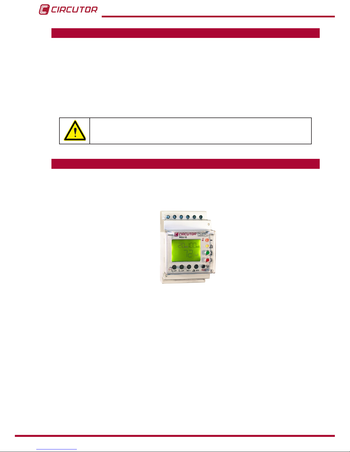
2�- DESCRIPTION OF THE PRODUCT
The RGU-10 earth leakage relay is type A programmable electronic earth leakage protection
device with two independent relays: the main output for checking the cut off device and performing the protection function and the pre-alarm relay for installation prevention and maintenance.
Allows the setting and adjustment of all parameters required for complete protection and maintenance checking in the installation. A series of parameters may be set directly from the keyboard (buttons) and by setting menus on the device itself.
Before starting the earth leakage device carefully read sections: power supply, connection diagram and setting.
The RGU-10 measures, calculates and displays the earth leakage current in three-phase, balanced or unbalanced industrial systems.
Measurements are in true effective value, via one earth leakage current input, from the WGC
family external measuring toroid.
Under normal operating conditions the main values determining earth leakage protection in an
installation are shown on the display. These include sensitivity, delay and instant current leakage.
Bearing in mind the high degree of protection required by installations, the device has a display
Page 7

7
Instruction Manual
RGU-10, RGU-10C
and LED indicators for the different events which usually occur.
Datadisplayedorpre-alarmindication,trips,leakagereadings,etc.assistinprovidingsufcient
information for proper maintenance.
Under normal operating conditions the backlit display is green. However, after any event causing a main relay to trip, the backlight is red, indicating the reason.
The version for RS-485 communications (RGU-10C) and appropriate software allows setting,
data and information to centralised for the proper monitoring and checking of the maintenance
of electricity lines.
The measurement of earth leakage current from which the RGU-10/RGU-10C operates by
indicating the instant leakage current, pre-alarm or trip is determined by the WGC series earth
leakagetransformers.Theinnerdiameterofthetransformerisdenedbytheinstallation’swiring dimensions.
There are 2 models of the device:
RGU-10, without communications.
RGU-10C, with communications RS-485.
Main features:
- Measuring in true effective value (TRMS)
- Type A differential (IEC 61008.1)
- Insulation against transients (IEC 61008.1)
-Highfrequencyltering(IEC61008.1)
-Tripsettingbetween80and100%I∆n
- Inverse curve (IEC 61008.1)
- Associated standard : IEC 61008.1, IEC755
- 3 modules. DIN rail. In a panel using front accessory
- Displaying instant leakage values.
- Backlit LCD display.
- RGU-10C Model : Built-in RS485 communications (Modbus RTU®).
Page 8
8
RGU-10, RGU-10C
Instruction Manual
3�- INSTALLING THE DEVICE
3.1.- PRELIMINARY RECOMMENDATIONS
The operators using and handling the device must follow the safety measures
established in the country where the device will be used to guarantee its safe
operation, using personal protective equipment if needed.
The RGU-10devicemustbeinstalledbyauthorisedandqualiedstaff.
Disconnect the device from the mains and disconnect the measuring devices before handling,
changing the connections of or replacing the device. Handling the device while it is connected
is hazardous to people nearby.
The cables must be in perfect working order to prevent accidents or injuries to people and/or
damage to the facilities/installations.
Limittheoperationofthedevicetomeasuringthespeciedcurrentorvoltagevalues.
The manufacturer of the device shall not be held responsible for any damage resulting from the
user or installation company failing to observe the warnings and/or recommendations indicated
in this manual nor for any damage resulting from the use of non-original products or accessories or those from other brands.
Do not use the device to take measurements if you detect an anomaly or malfunction.
Check the environment in which the device is installed before taking a measurement. Do not
use the device to take measurements in dangerous, explosive, wet or damp environments.
Disconnect the device from the mains and from the power supply (both the device
and its measuring system) before performing any maintenance work, repairs or
handling any of the connections of the device.
Contact the after-sales service if you detect that the device is not working properly.
Page 9
9
Instruction Manual
RGU-10, RGU-10C
3.2.- INSTALLATION
While the device is connected, the terminals, opening the cover or removing elements can expose parts that are hazardous to the touch. The device must not
be used until the installation process is complete.
The device is installed on a DIN rail or on a panel (drilled panel 67+1 x 67+1mm, according to DIN
43 700 using accessory). All connections must remain inside the electrical board.
3�2�1�- INSTALLATION OF DEVICE IN PANEL
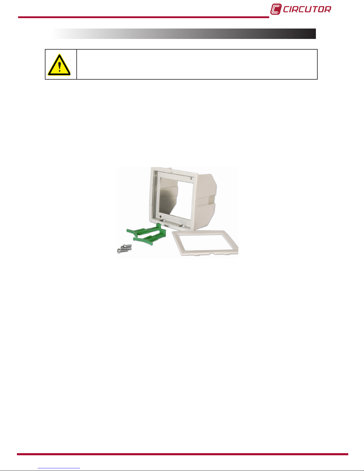
A 72x72 mm front adapter accessory is used to install the device on a panel. All connections
must remain inside the electrical board.
The front adapter accessory has a base, a frame two tabs and three screws, Figure 1.
Figure 1:Adapter accessory�
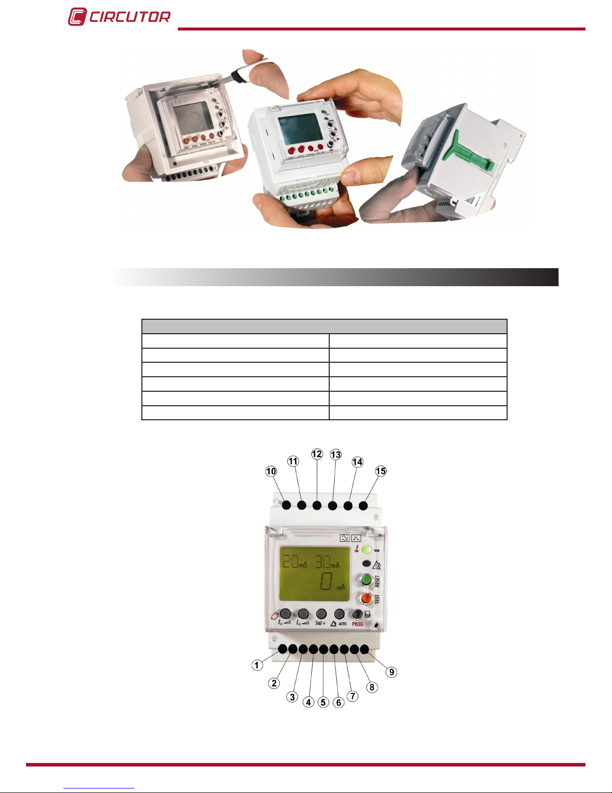
The steps to follow to perform the installation of the adapter accessory are:
1�- The base is mounted on top of the device.
2�- The device is attached by screwing the holes in the device on the upper right corner and
lower left corner on the front of device.
3�- The front frame is attached to cover the mounting points.
4�- Three green pressure tabs on the side runners of the base are attached.
5�- The device is mounted in the hole in the panel with the adapter.
6�- The tabs run towards the panel to obtain the mounting pressure.
Page 10
10
RGU-10, RGU-10C
Instruction Manual
Figure 2: Installation of adapter accessory
3.3.- TERMINALS OF THE DEVICE
Table 3:Terminal description RGU-10�
Terminals of the device
1: Voltage input ON/OFF external L 9: Toroid current input 1S2
2: Voltage input ON/OFF external N 10: Power supply voltage input A1
4: Output common contact pre-alarm 11: Power supply voltage input A2
5: NC output contact pre-alarm 13: NO output contact trip
6: NO output contact pre-alarm 14: NC output contact trip
8: Toroid current input 1S1 15: Output common contact trip
Note: Terminals 3, 7 and 12 are free.
Figure 3: RGU-10 terminals�
Page 11
11
Instruction Manual
RGU-10, RGU-10C
3.4.- CONNECTION DIAGRAMS
Note : It is recommended that meshed cable is used to connect the toroid over large distances.
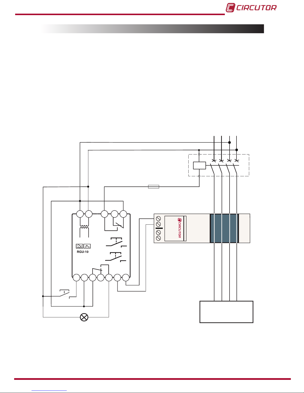
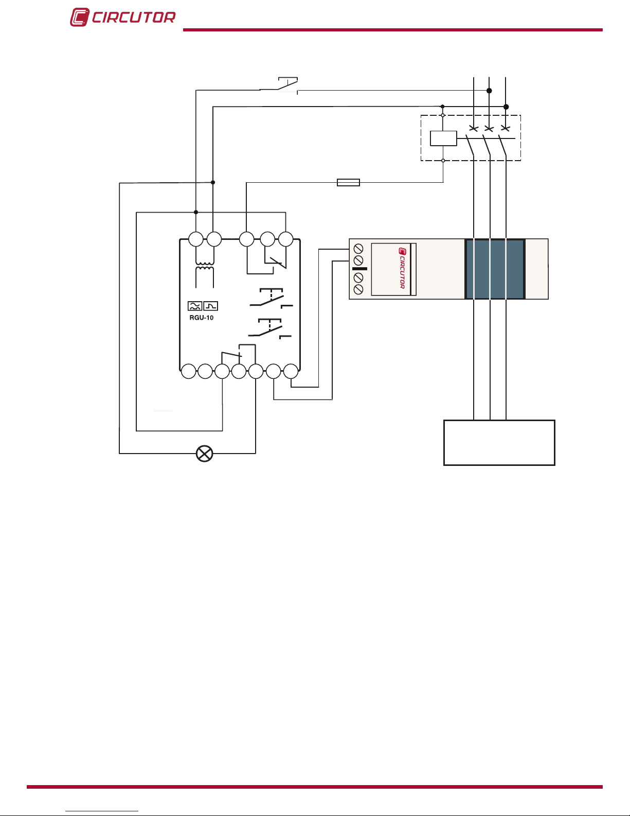
3�4�1�- CONNECTION WITH CURRENT EMISSION COIL
3�4�1�1�- Powering the device before the breaking device
In the event of powering the device before the breaking device (automatic switch) in an earth
leakage trip situation because of a fault, test or toroid error:
1�- Note the cause of the trip on the red display.
2�- Reset the breaking device.
3�- Press the RESET device.
NL1 L2
L3
1S1
1S2
Type
WGC
1S
1
1S
2
Reset
Test
1 2 4
5 6 8 9
10
11
13
14
15
UTILIZACIÓN
USE
ON / OFF externo
External ON / OFF
Disparo por BOBINA DE EMISIÓN
- Rearme Manual
Trip by SHUNT COIL
- Manual reclose
Figure 4: 24 ��� 230 Vac power supply
Page 12
12
RGU-10, RGU-10C
Instruction Manual
L1 L2
L3
1S1
1S2
Type
WGC
1S
1
1S
2
Reset
Test
1 2 4
5 6 8 9
10
11
13
14
15
UTILIZACIÓN
USE
Reset exterior
External Reset
Disparo por BOBINA DE EMISIÓN
- Rearme Manual
Trip by SHUNT COIL
- Manual reclose
Figure 5: 400 Vac power supply
Page 13
13
Instruction Manual
RGU-10, RGU-10C
3�4�1�2�- Powering the device after the breaking device
The following has to be taken into consideration in the event of powering device after the breaking device.
1�- The breaking device has to be a manually resettable device.
2�- After dripping, the device is disconnected losing all information on the reasons for the trip.
The system is reset only by resetting the breaking device. It is reconnected by the power supply.
NL1 L2
L3
1S1
1S2
Type
WGC
1S
1
1S
2
Reset
Test
1 2 4
5 6 8 9
10
11
13
14
15
UTILIZACIÓN
USE
ON / OFF externo
External ON / OFF
Disparo por BOBINA DE EMISIÓN
- Rearme Automático mediante corte de
alimentación
Trip by SHUNT COIL
- Automatic reclose by power supply out
Figure 6: 24 ��� 230 Vac power supply
Page 14
14
RGU-10, RGU-10C
Instruction Manual
L1 L2
L3
1S1
1S2
Type
WGC
1S
1
1S
2
Reset
Test
1 2 4
5 6 8 9
10
11
13
14
15
UTILIZACIÓN
USE
Disparo por BOBINA DE EMISIÓN
- Rearme Automático mediante corte de
alimentación
Trip by SHUNT COIL
- Automatic reclose by power supply out
Reset exterior
External Reset
Figure 7: 400 Vac power supply
The device operates to its maximum whenever it is supplied from the installation itself before
the breaking device or from an independent auxiliary power supply. However if the power supply from the installation is below the breaking device the system continues to be properly protected even though with limitations in terms of its disconnection performance through lack of
power supply.
Page 15

15
Instruction Manual
RGU-10, RGU-10C
3�4�1�3�- Power supply of the device independent of the installation
NL1 L2
L3
1S1
1S2
Type
WGC
1S
1
1S
2
Reset
Test
1 2 4
5 6 8 9
10
11
13
14
15
UTILIZACIÓN
USE
ON / OFF externo
External ON / OFF
Disparo por BOBINA DE EMISIÓN
- Rearme Manual
Trip by SHUNT COIL
- Manual reclose
+
-
Figure 8: 24 ��� 120 Vdc power supply
Page 16

16
RGU-10, RGU-10C
Instruction Manual
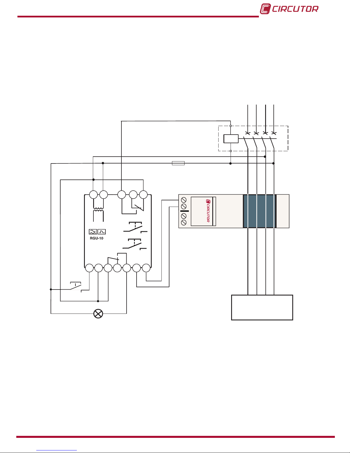
3�4�2�- CONNECTION WITH UNDERVOLTAGE COIL
3�4�2�1�- Powering the device before the breaking device
This breaking device may be an automatic switch or contactor.
Using a Contactor the protection is reset by pressing RESET, or by using an automatic switch.
The breaking device must be rearmed beforehand.
NL1 L2
L3
1S1
1S2
Type
WGC
1S
1
1S
2
Reset
Test
1 2 4
5 6 8 9
10
11
13
14
15
UTILIZACIÓN
USE
ON / OFF externo
External ON / OFF
Disparo por BOBINA DE MÍNIMA
- Rearme Manual
Trip by UNDERVOLTAGE COIL
- Manual reclose
Figure 9: 24 ��� 230 Vac power supply
Page 17

17
Instruction Manual
RGU-10, RGU-10C
L1 L2
L3
1S1
1S2
Type
WGC
1S
1
1S
2
Reset
Test
1 2 4
5 6 8 9
10
11
13
14
15
UTILIZACIÓN
USE
Reset exterior
External Reset
Disparo por BOBINA DE MÍNINA
- Rearme Manual
Trip by UNDERVOLTAGE COIL
- Manual reclose
Figure 10: 400 Vac power supply
Page 18

18
RGU-10, RGU-10C
Instruction Manual
3�4�2�2�- Power supply of the device independent of the installation
NL1 L2
L3
1S1
1S2
Type
WGC
1S
1
1S
2
Reset
Test
1 2 4
5 6 8 9
10
11
13
14
15
UTILIZACIÓN
USE
ON / OFF externo
External ON / OFF
Disparo por BOBINA DE MíNIMA
- Rearme Manual
Trip by UNDERVOLTAGE COIL
- Manual reclose
+
-
Figure 11: 24 ��� 120 Vdc power supply
Page 19

19
Instruction Manual
RGU-10, RGU-10C
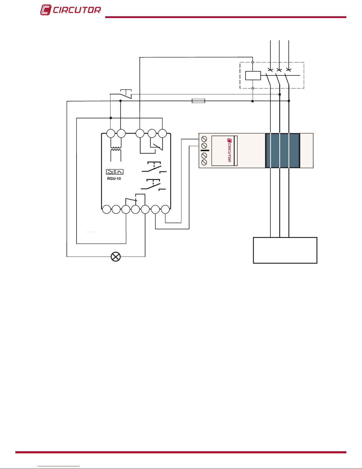
3�4�3�- CONNECTING THE DEVICE IN POSITIVE SAFETY
This installation mode provides the most conservative protection from the point of view of personal and property safety in electrical installations.
With this type of device connection and setting, persons all goods are protected against faults
where the earth leakage relay loses its protection capacity. The last order from the relay is to
open the installation in the event of this power supply problems to the device itself or through
lack of voltage in the installation (neutral or face fault).
3�4�3�1�- Connection with undervoltage coil
1�- The breaking device has the power to trip using the undervoltage coil, either internally (contactor) or externally (automatic switch).
2�- The device is set by programming by pressing Std/+ key in positive safety mode. The
“+”symbol appears on the display.
3�- The device’s power supply has to be the same as the installation or section it is protecting.
NL1 L2
L3
1S1
1S2
Type
WGC
1S
1
1S
2
Reset
Test
1 2 4
5 6 8 9
10
11
13
14
15
UTILIZACIÓN
USE
ON / OFF externo
External ON / OFF
Disparo por BOBINA DE MÍNIMA
- Rearme Manual
Trip by UNDERVOLTAGE COIL
- Manual reclose
Figure 12: Positive safety, undervoltage coil�
Page 20

20
RGU-10, RGU-10C
Instruction Manual
3�4�3�2�- Connection with current emission coil
When this type of safety is used using the current emission coil, it can only be assured that the
system will trip went the earth leakage relay is not operating correctly.
1�- The breaking device has the power to trip using the maximum current coil (automatic
switch).
2�- The device is set by programming by pressing Std/+ key in positive safety mode. The “+”
symbol appears on the display.
NL1 L2
L3
1S1
1S2
Type
WGC
1S
1
1S
2
Reset
Test
1 2 4
5 6 8 9
10
11
13
14
15
UTILIZACIÓN
USE
ON / OFF externo
External ON / OFF
Disparo por BOBINA DE EMISIÓN
- Rearme Manual
Trip by SHUNT COIL
- Manual reclose
Figure 13: Positive safety, current emission coil�
Page 21

21
Instruction Manual
RGU-10, RGU-10C
4�- OPERATION
4.1.- GENERAL DESCRIPTION
DIN RAIL
PANEL ( ADAPTER ACCESSORY)
INSTANT CURRENT LEAKAGE
DISPLAY
PRE-ALARM RELAY
RS-485 MODBUS
COMMUNICATIONS
PROGRAMMING OF
PARAMETERS
BACKLIT
LCD DISPLAY
SMALL SIZE:
3 MODULE
OUTPUT RELAY
CONTACT STATUS
SENSITIVITY from 50 ... 80% I∆N
DELAY from 20 ms ... 10 seconds
SENSITIVITY from 30 mA ... 30A
DELAY from 20 ms ... 10 seconds
GREEN Normal operation status.
RED Trip status by fault or other
event.
. MINIMUM Voltage
· Current EMISSION
ASSOCIATED BREAKING DEVICE
CONTACTOR. Connection by
undervoltage coil
EARTH LEAKAGE DEVICE WITH
TRIP COIL
TRIP COIL
ASSOCIATED MEASURING DEVICE
EARTH LEAKAGE TOROIDAL
WGC FAMILY
Page 22

22
RGU-10, RGU-10C
Instruction Manual
4.2.- DESCRIPTION OF THE DEVICE
The front of the equipment which is formed by the display, buttons and LEDs, is protected with a
sealable plastic cover which has the appropriate holes to access the RESET, TEST and PROG
keys.
Generic functions of the LEDs and front keypad:
Green LED : Device on
Red LED: Leakage trip
Yellow LED: Pre-alarm
Reset key
Sensitivity setting
Test key
Setup conguration
Pre-alarm conguration
Reset pre-alarm setting
Safety setting
Delay setting
Setup menu rotation
Figure 14: LEDs and keyboard description�
4.3.- LEDs INDICATORS
The device has 2 indicators LEDs, Figure 14.
Table 4: LEDs description: ON dual colour LED
ON Dual colour: Green - Red LED
State Description
Off The device is not operating or is not receiving power supply voltage.
Green The device is operating. It is receiving power supply voltage.
Red The device has tripped.
Page 23

23
Instruction Manual
RGU-10, RGU-10C
Table 5:LEDs description: Yellow LED�
Yellow LED
State Description
Off There is no pre-alarm trip.
On Pre-alarm trip without reclosing.
On
ashing
Pre-alarm trip in reclosing situation.
4.4.- KEYBOARD FUNCTIONS
The device has 7 keys, Figure 14.
1�- Keys accessible with sealed cover and tool�
RESET, Starts the equipment after a trip.
TEST, Carries out a trip to check the proper operation of the relay.
PROG/PAG, The function of the key depends on the duration of the touch.
Table 6:Operation of the PROG/PAG key�
Key Operation
PROG/
PAG
Short press
Access to Pre-alarm programming.
Long press
Access to the programming of the device by Setup.
2�- Keys accessible with cover raised
Keys with dual function. With a long press, the device is entered to set the values. With a short
press,theoptionwithinaseriesofvaluesdenedinthedeviceisselected.
SENSITIVITY,
It allows to choose between the values of 30, 100, 300, 500 mA, 1 and 3 A
This scale can be extended using the SETUP program to add 5, 10 and 30 A to the
above values.
DELAY,
It allows to choose between the values of 20,100, 200, 300, 400, 500, 750 ms and 1s.
This scale can be extended using the SETUP program to add 3, 5 y 10 s to the above
values.
This key also allows navigation within the SETUP MENU.
3�- Keys accessible with sealed cover and tool�
Flush buttons.
SAFETY, This allows the output contacts’ polarity to be set for both the main relay and
the pre-alarm.
With normal safety (Std) the relay is activated with a fault, the status is NO.
With positive safety (+) the relay is activated on supplying the device and is deactivated
Page 24

24
RGU-10, RGU-10C
Instruction Manual
with the fault, the status is NC.
RESET PRE-ALARM, This allows the automatic re-establishment of the pre-alarm sig-
nal to be enabled.
In Automatic Mode (REC), if the detected leakage current is below the preset pre-alarm
threshold, the relay becomes de-activated.
In manual mode, the device has to be RESET from the alarm screen in order to re-establish the pre-alarm system.
4.5.- DISPLAY
The device has a backlit display with green or red light, depending on the state of the device.
The background to the screen in normal mode is green. The parameters required for earth
leakage protection, sensitivity and delay in its associated units are displayed. It also displays
the current leakage current.
If the device trips through any event, the screen’s background changes to red and the reason
for the trip is displayed.
Figure 15: Display RGU-10�
Display messages by device trip, Table 7.
Table 7: Display messages by device trip
Message Cause of trip
TESt Test
ERRt Poor toroid connection
EXT Remote signal ON/OFF
REM RS-485 Communications
Instant value Current leakage
Other display messages, Table 8.
Table 8: Other display messages�
Message Description
SAVE Validatecongurationvalues
EXIT Exits programming mode
OVR Current leakage reading off scale
Page 25

25
Instruction Manual
RGU-10, RGU-10C
4.6.- OPERATION
When the device is powered at its rated voltage, the green LED ON the front is on, the backlit
LCD is green indicating the software and hardware version. After a short while, the version
disappears and the default display values appear on the display.
Figure 16:Initial screens�
The display shows the delay and sensitivity settings as well as the instant leakage current
reading.
While the device is operating, the display shows the following symbols while the device is being
programmed and set, Figure 17.
Conguration by
communications
Trip sensitivity
Instant current
leakage
Pre-alarm
conguration
Pre-alarm reclosing
Contact
polarity
Trip delay
Adjustment of
conguration
Figure 17: Display description�
In normal operating status the display shows the following parameters associated with the earth
leakage protection. Table 9�
Table 9: Parameters visible by display�
Parameter Units
Instant current leakage mA / A
Programmed trip delay, td ms / s
Programmedsensitivityoftrip,Id=I∆N mA / A
Main relay contact status
+ (contact 14-15 NO) / nothing (contact 14 - 15 NC)
+ (contact 16-15 NC) / nothing (contact 16 - 15 NO)
Page 26

26
RGU-10, RGU-10C
Instruction Manual
The RGU-10/ RG5-10C allow the display and setting of all required parameters to complete the
earth leakage protection adjustment with pre-alarm and communications.
Table 10: Adjustment parameters�
Parameter Units
Programmed pre-alarm trip delay ms / s
Sensitivityofpre-alarmin%I∆N %
Pre-alarm relay contact status
+ (contact 6-5 NO) / nothing (contact 6 - 5 NC)
+ (contact 4-5 NC) / nothing (contact 4 - 5 NO)
Operating frequency
(1)
Hz
Peripheral No
(1)
-
Baud rate
(1)
Bauds
Type of parity
(1)
-
(1)
RGU-10C only.
4.7.- TROUBLESHOOTING OR REASONS FOR TRIPPING
4�7�1�- POOR TOROID CONNECTION TRIP
After a certain time the device will carry out a test to detect the presence of the sensor or associated earth leakage transformer.
Also the “ERRt” error message will permanently appear on the RGU-10 display.
A short-circuit in the transformer secondary will also be detected as an error.
When this error is detected, the correct connection with the earth leakage transformer has to
be ensured and a RESET made to re-establish proper working. If the transformer is detected
again, normal status is returned and the error message disappears.
Figure 18: Trip by poor toroid connection�
4�7�2�- PRE-ALARM TRIP
In the event of the defaults current exceeding the programmed pre-alarm threshold, the yellow
LED will come on, the green backlit LCD will show the leakage level and the pre-alarm output
relay will be activated.
In automatic mode (REC) when the pre-alarm situation is removed, normal status is resumed
(LED and signal relay).
In manual mode, the device has to be RESET to unblock the pre-alarm.
Page 27

27
Instruction Manual
RGU-10, RGU-10C
4�7�3�- FAULT TRIP
When the device is tripped by a current fault, the red and yellow LED comes on and the backlit
LCD is red. There remains the display of the current of the last cycle that the relay has tripped.
To reconnect press RESET to return to the initial status.
Figure 19: Fault trip�
4�7�4�- REMOTE TRIP
When a trip is forced (input terminals 1-2, by applying 230 V) the device is tripped and disabled
and an “EXT” message is shown on the display in red and also the LED is on. It has to remain
permanently in this situation until the change in status no longer exists. It is not possible to
manually reset or reset using communications.
Figure 20: Remote trip�
When it is remotely reset (input terminals 1-2, removing the 230 Vac) the equipment is reconnected with the display backlit in green, LED ON in green as in normal status.
For the RGU-10C, a remote trip/reset can also be made via RS-485 communications. The device remains tripped showing this incidence on the display with a “REM” message in red with
also the LED ON. It has to remain permanently in this situation until the change in status no
longer exists.
Figure 21: Remote trip via RS-485�
It is reset when the remote reset is carried out using RS-485 communications, applying 230
Vac between the remote 1-2 input terminals or by pressing the RESET button. The device is
reconnected with the display backlit in green, LED ON in green as in normal status.
Page 28

28
RGU-10, RGU-10C
Instruction Manual
5�- CONFIGURATION
5.1.- DIRECT SETTING
By pressing for a long time on any of the direct setting buttons, PROG mode is entered (icon on
isplay) and the relay’s setting may be changed.
While in PROG mode if any other direct function is used (Id, td, Std/+ y Auto), the parameter
for the displayed relay can also be set.
PROG mode is exited if no buttons are pressed for a while with the last setting being “SAVE”.
5�1�1�- SETTING THE SENSITIVITY TRIP
Pressing Id for more than one second, PROG appears and a setting from the list is increased
witheverypress.Thecurrentsettingisseeninsmallguresandthenewsettinginthemain
gures.
Figure 22: Setting the sensitivity trip�
Possible setting values are: 30 mA, 100 mA, 300 mA, 500 mA, 1 A, 3 A, 5 A, 10 A and 30 A.
Note : The scale is limited, this is changed in the device’s SETUP. The default setting is a 3A
scale.
5�1�2�- DELAY SETTING AND MAIN RELAY CURVE
Pressing td for more than one second, PROG appears and a setting from the list including
curve types is increased with every press.
Thecurrentsettingisseeninsmallguresandthenewsettinginthemaingures.
Figure 23: Delay setting�
Possible setting values are: INS curve, SEL [S] curve, 20, 100, 200, 300, 400, 500, 750 ms,
1, 3, 5 and 10 s�
Note : The scale is limited, this is changed in the device’s SETUP. The curves belong to the 1
s scale which is the default scale.
Note : If the setting for I∆N is 30 mA, only instant settings are permitted: 20 ms, INS curves
Page 29

29
Instruction Manual
RGU-10, RGU-10C
or SEL.
5�1�3�-POSITIVE SECURITY SETTING OF THE MAIN RELAY
“Std”, contacts are on standby, terminals 14 - 15 (NC) and 13 - 15 (NO).
“+”, contacts change status on powering the device, the + sign is displayed. Terminals 14 -15
(NO) and 13 -15 (NC).
Figure 24: Positive security setting�
5�1�4�- SETTING THE PRE-ALARM RELAY
The PROG/PAG key control the pre-alarm relay and main relay settings using SETUP.
If the button is pressed for a short time the pre-alarm setting is entered. “Alarm” appears on the
display. Also the pre-alarm threshold appears as a % of the sensitivity setting and the pre-alarm
delay. To exit press PROG.
Figure 25: Setting the pre-alarm relay�
5�1�4�1�- Setting of the pre-alarm current
This is in terms of the program value in the main relay. Pressing Id enters to change the value.
Relative values are shown as a % of the preset trip current. Pressing Id changes the values:
OFF, 50, 60, 70, 80 and MAIN�
Where:
OFF: pre-alarm disabled
MAIN: the pre-alarm continues to trip the main channel.
Figure 26: Setting of the pre-alarm current�
Page 30

30
RGU-10, RGU-10C
Instruction Manual
5�1�4�2�- Pre-alarm time setting
This is in terms of the program value in the main relay. Pressing td enters to change the values.
Pressing td changes the values: 20, 50, 75, 100, 300, 500, 750 ms, 1, 3, 5 and 10 s�
Figure 27: Pre-alarm time setting�
5�1�4�3�- Pre-alarm positive safety setting
“Std”, contacts are on standby . Terminals : 4 - 5 (NC) and 6 - 5 (NO).
“+”, contacts change status on powering the device, the + sign is displayed. Terminals :4 – 5
(NO) and 6 – 5 (NC).
Figure 28: Pre-alarm positive safety setting�
5�1�4�4�- Reset pre-alarm setting
In the pre-alarm menu the REC function is shown as disabled or enabled. REC appears on the
display when it is enabled.
Figure 29: Reset pre-alarm setting�
Page 31

31
Instruction Manual
RGU-10, RGU-10C
5.2.- SETTING BY SETUP
“PROG”andtherstmenu option appearonthedisplaybypressingalongtimethePROG/
PAG key. Once in menu setting mode, the different text indicators appear on the display after
each time PROG is pressed.
When the correct menu is reached, the parameter can be changed by pressing td (rotating).
In order to enter the settings press the PROG but on again with the “SAVE” message showing
the version of the device. The display the turns to the initial screen.
If, after a certain time, the keyboard remains inactive the “EXIt” message appears and the main
relay settings are shown without any information being saved.
A�- RGU-10C congurationmenu
PROG
td
PROG
PROG
td
td
td
PROG
td
PROG
td
td
PROG
Figure 30: RGU-10C conguration menu.
Page 32

32
RGU-10, RGU-10C
Instruction Manual
B�- RGU-10 congurationmenu
PROG
td
PROG
td
td
PROG
Figure 31: RGU-10 conguration menu.
5.3.- CONFIGURATION THE MEASUREMENT SETUP
From measurement SETUP, the parameter settings for the RGU-10/RGU-10C can be displayed
and/or changed; this may match these parameters to the requirements of the system topologies
and/or applications
If it is an RGU-10C, this SETUP menu is preceded by the communications SETUP menu. If
there is no communications, RGU-10, is the only SETUP on the device.
The device does not save the setting changes until all of the setting has been entered using the
PROG key. When it detects that the keyboard has been inactive for a certain time it displays
“EXIt” and the setting menu is exited it without saving the changes.
Onenteringcongurationmode,ascreenisdisplayedinformingthatthedevicehasentered
congurationmodewiththePROGsymbolontheuppersectionoftherstmenuscreen.
5�3�1�- OPERATING FREQUENCY
The display shows FREQ. In order to change this press PROG. The value of the current
frequency appears on the upper left of the screen
In order to change the operating frequency, repeatedly press the td button increase in the digit
in the upper left corner.
When the value on the screen is the required value, enter and move onto the next menu by
pressing the PROG key. SETUP is exited with the SAVE message.
Page 33

33
Instruction Manual
RGU-10, RGU-10C
5�3�2�- SCALE LIMIT
The display shows LIM. In order to change this press PROG.Thenaldelayscalevaluesand
the actual current sensitivity settings appear on the upper section of the screen.
In order to modify the operational scale, repeatedly press the td button increasing the values of
the digits on the upper section of the screen. There are two scales, one in 10 seconds and 30
A and the other default scale in 1 second and 3 A.
When the required values are shown on the screen they are entered by pressing the PROG
button. SETUP is exited with the SAVE message.
5.4.- CONFIGURATION THE COMMUNICATION SETUP
Note: Only for RGU-10C models.
One or more RGU-10C devices may be connected to a computer or PLC in order to automate a
production process or an energy control system. As well as the usual operation of each device,
this system may centralize data at one single point; for this reason the RGU-10C has an RS485 communication output.
If more than one device is connected to one single series line (RS-485), it is necessary to assign to each a number or address (from 1 to 99) so that the central computer or PLC sends the
appropriate requests to these addresses for each peripheral.
From communication SETUP, the RGU-10C’s communication parameters may be displayed
and/or changed; this may match these parameters to the requirements of the system topologies
and/or applications.
The device does not save the setting changes until all of the setting has been entered using the
PROG button. When it detects that the keyboard has been inactive for a certain time it displays
“EXIt” and the setting menu is exited it without saving the changes.
To access communications SETUP press the PROG key.
On entering setting mode a screen is displayed showing that the device has entered communication setting mode.
Page 34

34
RGU-10, RGU-10C
Instruction Manual
To enter setting mode the PROG key must be pressed.
5�4�1�- PERIPHERAL NUMBER
The display shows PERI and the peripheral number on the upper left of the screen.
To write or change the number of the peripheral repeatedly press the td button, increasing the
value of the digit which is in the upper left corner.
When the required value is on the screen, it is entered and the display moves on to the next
menu by pressing PROG key, to allow the remaining values to be changed.
The peripheral number varies between 1 and 99.
5�4�2�- BAUD RATE
The display shows the letters “bd” on the upper left of the screen showing the bauds and shows
the baud rate in units of a thousand in the central part of the screen.
Repeatedly press the td button to change the baud rate, increasing the value of a digits on the
central area of the screen.
When the required value is on the screen, move on to the following digit by pressing PROG, to
allow the remaining values to be changed.
The possible setting values are as follows:
Page 35

35
Instruction Manual
RGU-10, RGU-10C
Table 11: Baud rate�
Value on screen Bauds
2.4
2400
4.8
4800
9.6 9600
19.2 19200
38.4
38400
54.6 54600
115
115000
5�4�3�- PARITY
The display shows “PARI” with the set a value on the upper left of the screen.
In order to change parity, repeatedly press the td key to change the values on the upper left of
the screen.
When the required value is on the screen, it is entered and the display moves on the next
screen by pressing PROG, to allow the setting to be changed.
ForcommunicationsettingmenuusingSETUPendsonthisscreen.Itdirectlylinkswiththerst
measurement SETUP screen on the device.
Page 36

36
RGU-10, RGU-10C
Instruction Manual
6�- RS-485 COMMUNICATIONS
RGU-10C devices feature one RS-485 communications port. The device has uses the MODBUS RTU communications protocol as the standard protocol.
6.1.- CONNECTIONS
The RS-485 cable must be wired with twisted pair cable with mesh shield (minimum 3 wires),
with a maximum distance between the RGU-10C and the master device of 1200 metres.
Up to 32 RGU-10C devices can be connected to this bus.
Use an intelligent RS-232 to RS-485 network protocol converter to establish the
communications with the master device.
B(-) A(+)
S (GND)
B(-)A(+) S
RS-232 / USB / Ethernet / Profibus ...
PC
RS-485
RS-485
RS-232
USB
Ethernet
Profibus
...
Figure 32: RS-485 Connection diagram�
Page 37

37
Instruction Manual
RGU-10, RGU-10C
6.2.- MODBUS PROTOCOL
In the Modbus protocol, the RGU-10C uses the RTU (Remote Terminal Unit) mode.
The Modbus functions implemented in the device are as follows:
Function 0x04: Reading integer registers.
Function 0x10: Writing multiple registers.
6�2�1� READ EXAMPLE: Function 0x04�
Query:
Address Function
Initial
Register
No� of
registers
CRC
0A 04 0000 000A 7176
Address: 0A, Peripheral number: 10 in decimal.
Function: 04, Read function.
Initial Register:0000, register from which to start reading.
No� of Registers: 000A, number of registers to be read: 10 in decimal.
CRC: 7176, CRC character.
Response:
Address Function
No� of
Bytes
Registers
CRC
nº 1 nº 2 nº 3 nº 4 nº 5 nº 6 nº 7 nº 8 nº 9 nº 10
0A 04 14 000A 0002 0000 0032 0000 0001 0000 0001 0014 0000 7EC9
Address: 0A, Responding peripheral number: 10 in decimal.
Function: 04, Read function.
No� of bytes: 14, No. of bytes received: 20 in decimal.
Registers: 000A, Address 0000h: Peripheral number : 10
0002, Address 00001h: Baud rate : 2 = 9600 bds
0000, Address 00002h: Type of parity : 0 = None
0032, Address 00003h: Operating frequency : 50 Hz
0000, Address 00004h: Trip current : 0 = 30 mA
0001, Address 00005h: Time for trip delay : 1 = INS
0000, Address 00006h: Relay output trip polarity : 0 = Standard
0001, Address00007h:%I∆ntripbypre-alarm.:1=50%
0014, Address 00008h: Time for pre-alarm delay: 1 = 20ms
0000, Address 00009h: Pre-alarm output relay polarity : 0 = Standard
CRC: 7EC9, CRC character.
Note : Each Modbus frame has a maximum limit of 26 registers.
Page 38

38
RGU-10, RGU-10C
Instruction Manual
6�2�2� WRITE EXAMPLE : Function 0x10�
Query:
Address Function
Initial
Register
No� of
registers
Nº de Bytes
Registers
CRC
Nº1 Nº2 Nº3 Nº4 Nº5
01 10 0000 0005 0A 0001 0003 0000 003C 0000 FF64
Address: 01, Peripheral number: 1.
Function: 10, Writing multiple registers.
Initial Register: 0000, Initial register of writing.
No� of bytes: 0A, No of bytes that are sent: 10
Registers : 0001, Address 0000h: Peripheral number : 1
0003, Address 00001h: Baud rate : 3 = 19200 bds
0000, Address 00002h: Type of parity : 0 = None
003C, Address 00003h: Operating frequency : 60 Hz
0000, Address 00004h: trip current : 0 = 30 mA
CRC: FF64, CRC character.
Response:
Address Function
Initial
Register
No� of
registers
CRC
01 10 0000 0005 000A
Nota : Each Modbus frame has a maximum limit of 26 registers.
6.3.- MODBUS COMMANDS
All Modbus map addresses are expressed in hexadecimal.
Table 12: Modbus memory map
Parameter Symbol Address
Reading /
Writing
Values Units
Peripheral No. PERI 0000 R/W 1 - 99 -
Baud rate bd 0001 R/W
2400-4800-9600-19200-
38400-57600-115200
bauds
Type of parity PARI 0002 R/W None - Odd - Even -
Operating frequency FREC 0003 R/W 50 - 60 Hz
Trip current Main relay Id 0004 R/W
0.03 - 0.1- 0.3 - 0.5 - 1 3 - 5 - 10
A
Delay time Main relay td 0005 R/W
INS - SEL - 0.02 - 0.1 -
0.3 - 0.4 - 0.5 - 0.75 - 1
- 3 - 5 -10
s
Contact polarity Main relay Std/+ 0006 R/W Standard - Positive -
Trip current Pre-alarm Id’ 0007 R/W OFF - 50 - 60 - 70 - 80 %
Delay time Pre-alarm td’ 0008 R/W
0.02 - 0.1 - 0.2 - 0.3 - 0.4
- 0.5 - 0.75 -1 - 3 - 5 - 10
s
Contact polarity Pre-alarm Std/+ 0009 R/W Standard - Positive -
Pre-alarm reclosing REC 000A R/W Manual - REC -
Page 39

39
Instruction Manual
RGU-10, RGU-10C
Table 12 (Continuation) : Modbus memory map
Parameter Symbol Address
Reading /
Writing
Values Units
Series No. (HI) - 000B R 18AD - 188C -
Series No. (LO) - 000C R 0000 - FFFF -
Device version - 000D R 0 -100 -
Relay contacts status - 0014 R
off - on (main)
on (pre-alarm)
-
Effective value Current leakage - 0015 R 0 - 65.000 mA
Effective value Trip current. - 0016 R 0 - 65.000 mA
Trip and external reset - 0019 W
0000 : Reset
FFFF : Test
-
Enable setting saving - 001A W
0000 : Enable
FFFF : Save
-
Page 40

40
RGU-10, RGU-10C
Instruction Manual
7�- TECHNICAL FEATURES
Power supply CA
Rated voltage
(2)
230 V ~ ± 20% 110 V ~± 20% 400 V ~ ± 20% 24 ... 48 V ~
Frequency 50 - 60 Hz
Consumption 6 VA
Power supply CC
Rated voltage
(2)
24 ... 125 V
Consumption 4 W
(2)
Depending on model.
Main relay / Pre-alarm output
Rated current 6 A ~
Maximum instant current 10 A ~
Rated voltage 230 V ~ / 400 V ~
(2)
Maximum switching voltage 250 V ~
Rated load in CA 2500 VA
Contacts protected by varistor 275 V ~
Mechanical useful life 10 x 10
6
Ambient temperature range - 40 ... 85 ºC
Electrical useful life for AC loads
Cut off power for DC loads
Note: Circutor guarantees that the RGU-10 / RGU-10C device complies with a response time of less than 30 ms
to 5In, and in combination with the selected cutting element must guarantee a total cut-off time of less than 40 ms
to comply with the IEC 60947-2-M standard.
External voltage input ON/OFF
Type Optocoupled
Maximum voltage
(1)
110 - 230 V ~± 20%
Maximum power 0.7 W
Earth leakage current measurement circuit
Scale range Full scale Resolution Display
30 mA 75 mA ± 1 mA
300 mA 750 mA ± 1 mA
3 A 7.5 A ± 0.1 A
30 A 75 A ± 1 A
Page 41

41
Instruction Manual
RGU-10, RGU-10C
Communications ( RGU-10C model)
Bus RS-485
Communications protocol Modbus RTU
Baud rate 2400 - 4800 - 9600 - 19200 - 38400 - 57600 - 115200 bauds
Stop bits 1
Parity without - even - odd
User interface
Display LCD
Keyboard 7 keys
LED 2 LEDs
Environmental features
Operating temperature -10ºC ... +50ºC
Relative humidity (without condensation) 5 ... 95%
Maximum altitude 2000 m
Protection degree
Mounted device: IP41 (Frontal)
Device without mounted : IP20 (Sides and back cover)
Mechanical features
Dimensions Figure 33
Weight 236 g.
Enclosure V0 self-extinguishing plastic
Fijación DIN rail
Connections
7 mm 0.127 ... 2.082 mm
2
0.5 ... 0.6 Nm stair road 0.4x2.5x80 mm
52,5
67,9
43,5
45
85
Figure 33: RGU-10 dimensions�
Safety / Standard
Designed for installations category III 300 V~ (EN 61010)
Protection against electric shock by class II double insulation�
Electrical accessories - Residual current monitors for household and
similar uses (RCMs)
IEC 62020
Low-voltage switchgear and controlgear -- Part 2: Circuit-breakers IEC 60947-2-M
General requirements for residual current operated protective devices IEC 60755
Residual current operated circuit-breakers without integral overcu-
rrent protection for household and similar uses (RCCBs) - Part 1: General rules
IEC 61008-1
Page 42

42
RGU-10, RGU-10C
Instruction Manual
8�- TECHNICAL SERVICE
9�- WARRANTY
• No returns will be accepted and no unit will be repaired or replaced if it is not ac-
companied by a report indicating the defect detected or the reason for the return.
•The guarantee will be void if the units has been improperly used or the storage, installation and maintenance instructions listed in this manual have not been
followed.“Improperusage”isdenedasanyoperatingorstorageconditioncon-
trary to the national electrical code or that surpasses the limits indicated in the
technical and environmental features of this manual.
• CIRCUTOR accepts no liability due to the possible damage to the unit or other
parts of the installation, nor will it cover any possible sanctions derived from a possible failure, improper installation or “improper usage” of the unit. Consequently,
this guarantee does not apply to failures occurring in the following cases:
- Overvoltages and/or electrical disturbances in the supply;
-Water,iftheproductdoesnothavetheappropriateIPclassication;
- Poor ventilation and/or excessive temperatures;
- Improper installation and/or lack of maintenance;
-Buyerrepairsormodicationswithoutthemanufacturer’sauthorisation.
CIRCUTOR
guarantees its products against any manufacturing defect for two years after the
delivery of the units.
CIRCUTOR will repair or replace any defective factory product returned during the guarantee
period.
In the case of any query in relation to device operation or malfunction, please contact the
CIRCUTOR, SA Technical Support Service.
Technical Assistance Service
Vial Sant Jordi, s/n, 08232 - Viladecavalls (Barcelona)
Tel: 902 449 459 ( España) / +34 937 452 919 (outside of Spain)
email: sat@circutor.com
Page 43

43
Instruction Manual
RGU-10, RGU-10C
10�- CE CERTIFICATE
Page 44

44
RGU-10, RGU-10C
Instruction Manual
Page 45

45
Instruction Manual
RGU-10, RGU-10C
Page 46

CIRCUTOR, SA
Vial Sant Jordi, s/n
08232 - Viladecavalls (Barcelona)
Tel: (+34) 93 745 29 00 - Fax: (+34) 93 745 29 14
www.circutor.es central@circutor.com
 Loading...