

Page 1

Relé de protección diferencial electrónico series RGE / RGE-R
RGE / RGE-R series Electronic Earth-leakage Protection Relay
Código
code
P12201 RGE-0,03 0,03 Fijo/Fixed 0,02 Fijo/Fixed
P12211 RGE-0,3 0,3 Fijo/Fixed 0,02 Fijo/Fixed
P12221 RGE-0,5 0,5 Fijo/Fixed 0,02 Fijo/Fixed
P12231 RGE
Seleccionable/Selectable Seleccionable/Selectable
P12232 RGE
Seleccionable/Selectable Seleccionable/Selectable
DESCRIPCIÓN GENERAL
- Relé electrónico diferencial tipo A superinmunizado ( IEC 60755, IEC 60947-2)
- Funciona con toroidal externo serie WG/WGS, mm según instalación.
- La deteccion de la fuga, se realiza haciendo un muestreo de la corriente diferencial,
calculando su verdadero valor eficaz (TRMS).
- Salida relé contacto conmutado (NA/NC) que actúa sobre elemento de corte.
- Montaje en Carril DIN 46277 (EN 50022)
CONSIDERACIONES INICIALES
COMPROBACIONES A LA RECEPCIÓN
Asegurarse del cumplimiento de:
- El equipo corresponde a las especificaciones de su pedido.
- El equipo no ha sufrido desperfectos durante el transporte.
Para más información, puede descargarla de nuestra web, www.circutor.es
PRECAUCIONES DE SEGURIDAD
Para la utilización segura del equipo, es fundamental que las personas que lo instalen o manipulen, sigan
las medidas de seguridad habituales, así como las advertencias en dicha guía rápida.
La serie RGE es un equipo diseñado específicamente para ser instalado dentro de un cuadro eléctrico o
envolvente, con fijación en carril DIN o en panel mediante accesorio. Dispone de led luminoso (ON)
indicando que hay presencia de tensión. Aunque este led no esté encendido, no exime al usuario de
comprobar que el equipo está desconectado de toda de toda fuente de alimentación.
INSTALACIÓN Y PUESTA EN MARCHA
La presente guía rápida contiene informaciones y advertencias que el usuario tiene que respetar para
garantizar el funcionamiento seguro del equipo. En su funcionamiento habitual no debe ser utilizado hasta
su instalación definitiva en el cuadro eléctrico.
Si se utiliza el equipo de forma no especificada por el fabricante, la protección puede resultar
!
comprometida.
Cuando sea probable que el equipo haya perdido la protección de seguridad (presencia de daños visibles)
debe desconectarse la alimentación del equipo. En este caso póngase enc contacto con el servicio técnico
cualificado, o bien, con nuestro S.A.T. (Servicio Asistencia Técnica).
INSTALACIÓN DEL EQUIPO
Uso en instalación monofásica (fase y neutro, L y N), trifásica (las tres fases, L1,L2 yL3) o trifásica mas
neutro (L1, L2, L3 y N). Por el toroidal asociado WG/WGS tiene que pasar todos los cables que alimentan
la carga a o parte de instalación a proteger. El cable de tierra nunca. Instalable en carril DIN. Alimentación
monofásica (fase y neutro, L-N) . Se aconseja proteger la fase mediante fusible tipo gL. Sección de cable
permitida hasta 1,5 mm . Conexionado mediante tornillos. Par de apriete máximo de 0,5-0,6 N. Se realiza
la conexión al enbornado 1S1-1S2 del toroidal WG/WGS que realiza la función de sensor. La salida de relé
se lleva a la bobina de disparo para actuar sobre el interruptor automático y que realice el corte de
suministro eléctrico, protegiendo a personas y bienes de posibles electrocuciones o incendios.
Alimentación equipo
Tensión de 400, 230 ,110 Vc.a. +/- 20% - 50/60 Hz - 3 VA
Tensión de 24 a 120 Vc.c. +/- 15% - 2,5 W
Condiciones de trabajo
Temperatura -10 ...50 C,Humedad relativa 95%
Altura máxima de trabajo 2.000 m
Seguridad
Categoria III - 300 Vc.a. EN61010
Protección al choque eléctrico doble aislamiento clase II
Protección IP20
CONEXIONADO MEDIANTE BORNAS ATORNILLABLES
DESCRIPCIÓN DE BORNES CARACTERÍSTICAS
4 SIN USO
5 ALIMENTACIÓN (FASE o NEUTRO)
6 ALIMENTACIÓN (NEUTRO o FASE)
7 ENTRADA 1S1 DEL TOROIDAL WG/WGS
8 ENTRADA 1S2 DEL TOROIDAL WG/WGS
1 CONTACTO SALIDA RELÉ DISPARO NA
2 CONTACTO SALIDA RELÉ COMÚN
3 CONTACTO SALIDA RELÉ DISPARO NC
2
¡ IMPORTANTE !
35
5
678
85
1 2
DIMENSIONES/DIMENSIONS (mm)
Ver alimentacion del equipo.
Transformadores diferenciales con relación de
transformación 500:1
Tensión Nominal: 230 Vc.a. / 110 Vc.a.
- Corriente Máxima: 10 Ac.a.
- Potencia Máxima: 2.500 V·A
- Endurancia electrica: 100.000 operaciones,
6 A, 85 ‘C. Carga resistiva Ue/Ie: 250 Vca/ 8 Aca
Tensión Nominal: 400 Vc.a.
- Corriente Máxima: 10 Ac.a.
- Potencia Máxima: 2.500 V·A AC1
500 V·A AC15
- Endurancia electrica: 100.000 operaciones, Ac1
6 A, 85 ‘C. Carga resistiva Ue/Ie: 250 Vca/ 8 Aca
Tensión Nominal: 24 ... 120 Vc.c.
- Corriente Máxima apertura: gráfico adjunto
3
Tipo
Type
-R1 0,03-0,1-0,3-0,5-1-2-3 0,02-0,1-0,2-0,3-0,5-0,7-1
-R 0,03-0,1-0,3-0,5-1-3-5 0,02-0,1-0,3-0,5-1-3-5
45
67
Fixation on profile
4
Fijacion sobre perfil /
5
RGE-0,03/0,3/0,5
RGE-R/R1
1 2
Sensibilidad (A)
Sensivity
Retardo disparo (s)
Tripping delay
P 1 X X X X 0 0 X
Código
Code
Tensión de
alimentación
Power supply
Por ejemplo RGE-R alimentado a 48 Vc.c
For instance RGE-R Vd.c...supplied by 48
Código interno
Internal code
230 Vc.a./a.c.
110 Vc.a./a.c.
400 Vc.a./a.c.
24 ... 48 Vc.a./a.c.
24 ... 125 Vc.c./d.c.
P122320040000
GENERAL DESCRIPTION
- Super-inmunized Type A electronic e . (IEC60755, IEC 60947-2)
- Use with core balance transformer WG/WGS series, mm depends instal.lation.
- Detection of the leakage current in true RMS value by sampling.
- Output relay contacts commands over external breaking element to protection trip.
- Mounting in DIN rail 46277 (En50022)
arth leakage relay
PRELIMINARY CONSIDERATIONS
CHECKS ON RECEPTION
On receving the instrument, check the following points:
- The unit’s specifications are the same as those on your order.
- Check that the device has not suffered any damage during transport.
You can download more information from CIRCUTOR website, www.circutor.es
SAFETY PRECAUTIONS
The staff using or handling the unit must follow the common safety measures and warnings included in the
instruction manual.
The RGE unit has been specifically designed for its installation in a electric board, enclosure to a DIN rail or
mounted in panel by means of accesories. It has a flashing green led (ON) when it is operation and,
therefore, it shows that there is voltage and current in the electronic circuit. The user must make sure that
the equipment is not conected to the power supply at all the times, even when the LED is not flashing.
INSTALLATION AND START-UP
The user must take into account and observe the informations and warnings included in this instruction
manual to guarantee the correct operation of the equipment and comply whit the safety specifications. The
equipment must not turned on until is fully installed in the electrical panel.
The unit´s protections systems might not be effective if the unit is used for purpose other than
!
those specifications by the manufacturer.
Disconnect the equipment from the power supply when the unit´ssafety protection systems are not working
or there are signs of a problem (in case of visible damage). In this case, contact a qualified technical service
or with our own technical service (TAS).
INSTALLING THE EQUIPMENT
Use in single-phase installation (phase and neutral, L and N), three phase - 3 wires (three phases, L1, L2
and L3) or three phases - 4 wires (L1, L2, L3 and N). On the inside of the hole of core balance transformers
WG/WGS series must pass all live conductors supplyng electrical energy to loads or part of the installation
which requires it to earth leakage protection with this device. Never must pass the protective conductor
(PE). DIN rail installation. Power Supply single phase (phase and neutral, L-N). It is advisable to protect the
phase (L) by Fuse type gL. Wire section allowed up 1.5 mm2. Connection with screws. Maximum torque of
0.5-0.6 N. It makes the connection to the 1S1-1S2 terminals of core balance transformer WG / WGS that
performs the function of sensor. The relay output is taken to the trip coil to act on the breaker, protecting
DIN 46277 (EN 50022)
678
3
4
68
64
TERMINAL DESCRIPTIÓN FEATURES
4 WITHOUT USE
5 SUPPLY (Phase or Neutral)
6 SUPPLY (Neutral or Phase)
7 INPUT 1S1 C.B.Transformer WG/WGS
8 INPUT 1S2 C.B.Transformer WG/WGS
1 OUTPUT RELAY NO
2 OUTPUT RELAY COMMON
3 OUTPUT RELAY NC
¡ IMPORTANT !
People and property from possible electric shock or fire.
Power supply
Voltage 400, 230 ,110 Va.c. +/- 20% - 50/60 Hz - 3 VA
Voltage 24 to 120 Vd.c. +/- 15% - 2,5 W
Operating conditions
Temperature -10 ...50 C,Relative humidity 95%
Max. Altitude 2.000 m
Safety
Category III - 300 Vc.a. EN61010
Double - insulated electric shock protection clas II
Protection IP20
CONNECTION VIA SCREW TERMINALS
See Power Supply features
Core balance Transformer with ratio 500:1
Rated Voltage: 230 Va.c. / 110 Va.c.
- Maximun Current: 10 A a.c.
- Maximun power: 2.500 V·A
- Electrical endurance: 100.000 operations,
6 A, 85 ‘C. Resistive Load Ue/Ie: 250 Va.c./8 Aa.c.
Rated Voltage: 400 Va.c.
- Maximun Current: 10 A a.c.
- Maximun power: 2.500 V·A AC1
500 V·A AC15
- Electrical endurance: 100.000 operations, AC1
6 A, 85 ‘C. Resistive Load Ue/Ie: 250 Va.c./8 Aa.c.
Rated Voltage: 24 ... 120 Vd.c.
- Maximun load breaking capacity: see the graphic
depending on voltage.
0
1
3
4
Servicio de Asistencia Técnica
En caso de cualquier duda de funcionamiento o avería del equipo avisar al servicio de asistencia técnica
CIRCUTOR, SA
Vial Sant Jordi s/n
08232 Viladecavalls (Bacelona), ESPAÑA
Tel: 902 449 459 (España)
Tel: (+34) 93 745 29 00 (fuera de España)
E-mail: sat@circutor.es
Technical Assistance
If you have any doubts about the running of the equipment or any faults, contact the service staff.
CIRCUTOR, SA
Vial Sant Jordi s/n
08232 Viladecavalls (Bacelona) SPAIN
Tel: (+34) 93 745 29 00
E-mail: sat@circutor.es
M98143701-20-13A
Page 2
Relé de protección diferencial electrónico series RGE / RGE-R
RGE / RGE-R series Electronic Earth-leakage Protection Relay
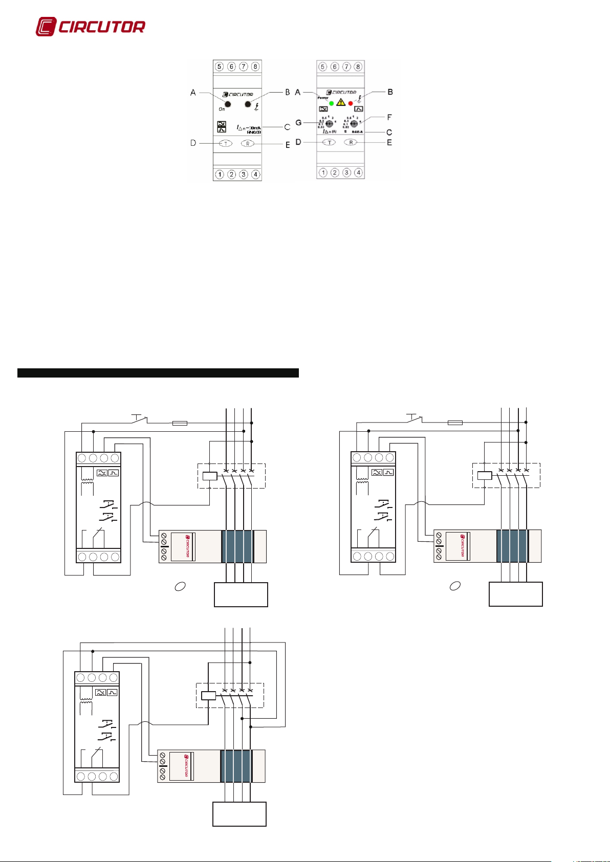
DESCRIPCIÓN DE LOS LED Y PULSADORES
- Indicación del estado del equipo mediante 2 LED’s.
- TEST y RESET del equipo mediante 2 pulsadores.
- Ajuste del equipo mediante 2 pulsadores (solo RGE-R/R1)
A. Led de funcionamiento (verde)
B. Led de fuga o estado protección diferencial (rojo)
C. Modelo (y sensibilidad) del relé
D. Pulsador TEST
E. Pulsador rearme rele
F. Selección de sensibilidad
G. Selección de retardo al disparo.
INDICACIONES POR LED
- DISPARO RELÉ.
Led de fuga (rojo) encendido permanentemente.
- SEÑALIZACIÓN FALLO TOROIDAL.
Led de funcionamiento parpadeando (verde) y led de fuga encendido (rojo).
- SEÑALIZACIÓN PREALARMA. Solo RGE-R/R1
Led de fuga (rojo) parpadeando, valor de fuga inferior al seleccionado.
- 1 destello cada 2 seg. : corriente de fuga = 25 ... 50% de la corriente de disparo.
- 1 destello cada 1 seg. : 50 ... 75%
- 2 destellos cada 1 seg. : 75 ... (<) 100%
DISPARO DEL EQUIPO
Los contactos de salida del relé conmutado (bornes 1-2-3) cambian de posición.
- Por FUGA de CORRIENTE. Cuando detecta mediante toroidal externo serie WG/WGS
que la corriente de fuga está muy cerca o supera la sensibilidad nominal en el equipo, ya
sea fija o ajustada.
- Por TEST. Mediante pulsador TEST. Comprueba que la protección diferencial funciona.
Se aconseja realizarlo periódica mente.
RECONEXIÓN DEL EQUIPO
- Por pulsador RESET. Pulsar directamente en el equipo. Se vuelve al estado inicial del
mismo, led verde encendido y led de fuga no encendido permanentemente.
- Por RESET EXTERIOR. Se instala un pulsador seriado en la alimentación del equipo. Al
pulsarlo el equipo se apaga y se reinicia el equipo.
LEDS AND BUTTONS DESCRIPTIÓNS
- Status indication by means 2 LED’s.
- TEST and RESET by means 2 push-buttons.
- Adjustment equipment parameters by means 2 selectors (only RGE-R/R1)
A. Power Led (green)
B. Status leakage current Led (red)
C. Relay¨s model (and sensivity)
D. Pus-button for the relay`s TEST
E. Pus-button for the relay`s RESET
F. Relay`s sensivity selection
G.Relay`s delay selection
- .
Leakage current led (red) permanently lit. Trip of the relay.
- CONTINUITY FAILURE WITH C.B.TRANSFORMER (WG/WGS).
Power led blinking (verde) and leakage current led lit permanently.
- PREALARM SIGNAL. Only RGE-R/R1
Leakage current led blinking, leakage current value lower than selected (sensivity).
- 1 blink every 2 s : leakage current = 25 ... 50% sensivity (trip current).
- 1 blink every 1 s : 50 ... 75%
- 2 blinks every 1 s : 75 ... (<) 100%
INDICATION BY LED
TRIP RELAY
EQUIPMENT TRIP
The output relay contacts (terminals 1-2-3) change. 1-2: NO>NC and 2-3: NC>NO
- By LEAKAGE CURRENT. When detected by external toroidal WG/ WGS series that the
leakage current is very close to or exceeds the nominal sensitivity on the relay, either fixed
or adjusted
- By TEST. Push-button TEST. Verify that the earht leakage protection work. It is advisable
to do regulary.
RECLOSING THE EQUIPMENT
- By push-button RESET. Push directly on the equipment. It returns to the initial state,
green led ON and leakage current led OFF.
- By EXTERNAL RESET. Serial switch must be installed in the relays's power. When
pressed the equipment shuts down and restarts him again.
ESQUEMAS DE CONEXIÓN / WIRING DIAGRAM
Reset Exterior, external reset
Disparo por
5
678
RGE-0,03/0,3/0,5
RGE-R/R1
Reset
Test
3
678
RGE-0,03/0,3/0,5
RGE-R/R1
4
1 2
- Rearme manual, manual reclose R
- Reset Exterior, external reset
5
BOBINA EMiSION
Trip by
SHUNT COIL
1S1
1S1
T
1S2
ype WG
1S2
Disparo por
BOBINA EMiSION
Trip by
SHUNT COIL
CARGA
CARGA
USE
L3
CARGA
CARGA
USE
NL1 L2
L3
NL1 L2
L3
NL1 L2
Reset Exterior, external reset
Disparo por
5
678
RGE-0,03/0,3/0,5
RGE-R/R1
Reset
Test
3
1 2
- Rearme manual, manual reclose R
- Reset Exterior, external reset
4
BOBINA MINIMA
Trip by
UNDERVOLTAGE
COIL
1S1
1S1
1S2
1S2
T
ype WG
Reset
Test
1S1
1S1
1S2
3
1 2
- Rearme automático mediante elemento
de corte / automatic reclose by breaking
element.
4
1S2
T
ype WG
CARGA
CARGA
USE
M98143701-20-13A
 Loading...