

Page 1
Impulse sensor
ReadWatt
INSTRUCTION MANUAL
(M018B01-03-14B)
Page 2

ReadWatt
2
Instruction Manual
Page 3
ReadWatt
SAFETY PRECAUTIONS
Follow the warnings described in this manual with the symbols shown below.
DANGER
Warns of a risk, which could result in personal injury or material damage.
ATTENTION
Indicates that special attention should be paid to a speci c point.
If you must handle the unit for its installation, start-up or maintenance, the following
should be taken into consideration:
Incorrect handling or installation of the unit may result in injury to personnel as well as damage
to the unit. In particular, handling with voltages applied may result in electric shock, which may
cause death or serious injury to personnel. Defective installation or maintenance may also
lead to the risk of re.
Read the manual carefully prior to connecting the unit. Follow all installation and maintenance
instructions throughout the unit’s working life. Pay special attention to the installation standards of the National Electrical Code.
Refer to the instruction manual before using the unit
In this manual, if the instructions marked with this symbol are not respected or carried out correctly, it can
result in injury or damage to the unit and /or installations.
CIRCUTOR, SA reserves the right to modify features or the product manual without prior noti cation.
DISCLAIMER
CIRCUTOR, SA reserves the right to make modi cations to the device or the unit speci ca-
tions set out in this instruction manual without prior notice.
CIRCUTOR, SA on its web site, supplies its customers with the latest versions of the device
speci cations and the most updated manuals.
www.circutor.com
Instruction Manual
3
Page 4

ReadWatt
CONTENTS
SAFETY PRECAUTIONS �����������������������������������������������������������������������������������������������������3
DISCLAIMER ������������������������������������������������������������������������������������������������������������������������ 3
CONTENTS ��������������������������������������������������������������������������������������������������������������������������� 4
REVISION LOG ��������������������������������������������������������������������������������������������������������������������� 5
1�- VERIFICATION UPON RECEPTION ������������������������������������������������������������������������������� 6
2�- PRODUCT DESCRIPTION ���������������������������������������������������������������������������������������������� 6
3�- UNIT INSTALLATION ������������������������������������������������������������������������������������������������������7
3�1�- PRIOR RECOMMENDATIONS �������������������������������������������������������������������������������� 7
3�2�- INSTALLATION �������������������������������������������������������������������������������������������������������� 8
3�3�- UNIT TERMINALS ������������������������������������������������������������������������������������������������� 10
3�4�- CONNECTION DIAGRAM ������������������������������������������������������������������������������������� 11
3�4�1�- RS-485 CONNECTION ������������������������������������������������������������������������������� 11
3�4�2�- PULSE OUTPUT CONNECTION ��������������������������������������������������������������� 12
4�- OPERATION �����������������������������������������������������������������������������������������������������������������13
4�1�- IMPULSE LED ������������������������������������������������������������������������������������������������������� 13
4�2�- IMPULSE OUTPUT ������������������������������������������������������������������������������������������������ 13
4�3- COMMUNICATIONS ����������������������������������������������������������������������������������������������� 14
4�3�1�- MODBUS PROTOCOL ������������������������������������������������������������������������������� 14
4�3�2�- READ COMMANDS������������������������������������������������������������������������������������ 14
4�3�3�- WRITE COMMANDS ���������������������������������������������������������������������������������� 15
4�3�4�- MODBUS VARIABLES ������������������������������������������������������������������������������� 15
4�3�5�- SPECIAL BROADCAST COMMAND ��������������������������������������������������������� 16
5�- TECHNICAL FEATURES �����������������������������������������������������������������������������������������������18
6�- MAINTENANCE AND TECHNICAL SERVICE �������������������������������������������������������������� 20
7�- GUARANTEE ����������������������������������������������������������������������������������������������������������������� 20
8�- CE CERTIFICATE ���������������������������������������������������������������������������������������������������������� 21
4
Instruction Manual
Page 5

ReadWatt
REVISION LOG
Table 1: Revision log�
Date Revision Description
03/14 M018B01-03-14A Initial Version
04/14 M018B01-03-14B Changes : Points 3.4, 4.3.4 and 5
Instruction Manual
5
Page 6
ReadWatt
1�- VERIFICATION UPON RECEPTION
Check the following points when you receive the unit:
a) The unit meets the specications described in your order.
b) The unit has not suffered any damage during transport.
c) Perform an external visual inspection of the unit prior to switching it on.
d) Check that it has been delivered with the following:
- A Velcro strap to attach the unit to the energy meter with impulse emitter,
- A connection cable,
- A CD.
If any problem is noticed upon reception, immediately contact the transport
company and/or CIRCUTOR's after-sales service.
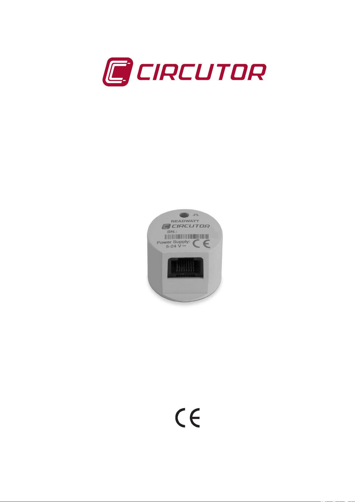
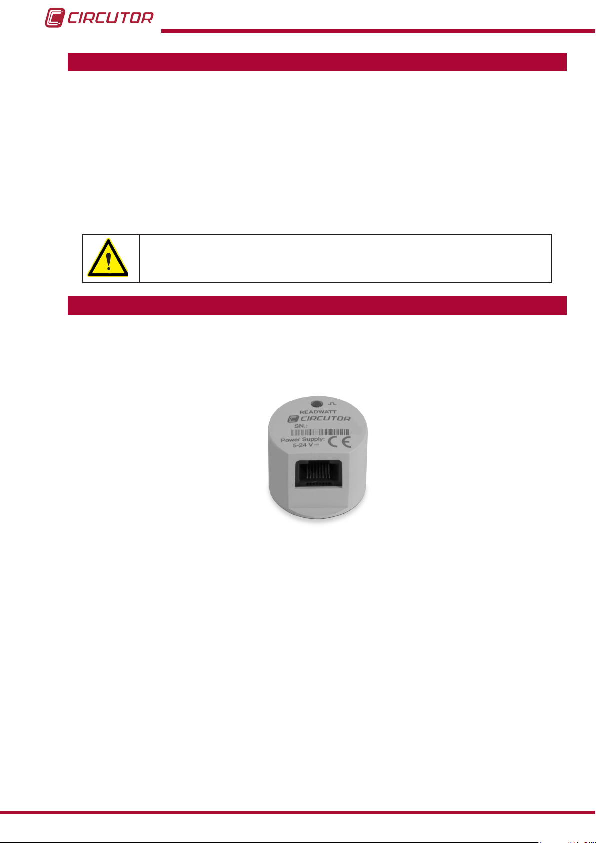
2�- PRODUCT DESCRIPTION
ReadWatt is an impulse sensor that can be attached to an energy meter verication impulse
emitter so that, through a MODBUS RTU protocol, there is an energy totaliser with the same
accuracy as the meter itself, but without physical access being necessary.
The unit features:
- 1 impulse indicator LED.
- 1 impulse output.
- RS-232 communications with MODBUS RTU protocol.
- RS-485 communications with MODBUS RTU protocol.
6
Instruction Manual
Page 7

ReadWatt
3�- UNIT INSTALLATION
3.1.- PRIOR RECOMMENDATIONS
In order to use the unit safely, it is critical that individuals who handle it follow
the safety measures set out in the standards of the country where it is being
used, use the necessary personal protective equipment, and pay attention to
the various warnings indicated in this instruction manual.
The ReadWatt unit must be installed by authorised and qualied staff.
The power supply plug must be disconnected before handling, altering the connections or
replacing the unit. It is dangerous to handle the unit while it is powered.
Also, it is critical to keep the cables in perfect condition in order to avoid accidents, personal
injury and damage to installations.
The manufacturer of the unit is not responsible for any damage resulting from failure by the
user or installer to heed the warnings and/or recommendations set out in this manual, nor for
damage resulting from the use of non-original products or accessories or those made by other
manufacturers.
If an anomaly or malfunction is detected in the unit, do not use it to take any measurements.
Inspect the work area before taking any measurements. Do not take measurements in dangerous areas or where there is a risk of explosion.
Disconnect the unit from the power supply (unit and measuring system power
supply) before maintaining, repairing or handling the unit's connections.
Please contact the after-sales service if you suspect that there is an operational
fault in the unit.
The installation where the unit is connected must have an earthing and the DC
ripple voltage of the power supply cannot exceed 10%.
Instruction Manual
7
Page 8

ReadWatt
3.2.- INSTALLATION
The unit is installed on the energy meter.
The rst step for installing ReadWatt is to separate the two parts of the Velcro strap. Take one
of them, remove the protective paper and stick the adhesive part of the Velcro strap to the
rear of the unit ( Figure 1).
Figure 1: Stick part of the Velcro strap to the rear of the READWATT�
Remove the protective paper from the other part of the Velcro strap and stick the adhesive
part to the optical port of the billing meter (Figure 2).
Figure 2: Stick a part of the Velcro strap to the optical port of the meter�
8
Instruction Manual
Page 9

ReadWatt
Now simply place the ReadWatt on the energy meter's Velcro strap (Figure 3).
Figure 3: ReadWatt installed�
Finally, connect the cable delivered with the unit to the ReadWatt's RJ45 connector.
Figure 4: Cable connection�
Instruction Manual
9
Page 10

3.3.- UNIT TERMINALS
The unit has a RJ45 connector with the following list of terminals (Table 2):
Table 2:List of ReadWatt terminals�
Unit terminals
1: GND 5: B(-), RS-485
2: Rx, RS-232 6: GND
3: Tx, RS-232 7: Pulse output
4: A(+), RS-485 8: Vdc, Auxiliary power supply.
ReadWatt
Figure 5: ReadWatt RJ45 Connector�
10
Instruction Manual
Page 11

ReadWatt
3.4.- CONNECTION DIAGRAM
3�4�1�- RS-485 CONNECTION
Use an intelligent RS-232 to RS-485 network protocol converter to establish the
communications with the master unit ( Figure 6).
3
PC
5
2
Alimentación
Power Supply
-
+
B
A
(+)
(-)
RS-232
2 53
ReadWatt
1
2
RS-485
B(-)A(+)
A(+)
Alimentación
Power Supply
B(-)
Instruction Manual
Figure 6: RS-485 Connection diagram�
11
Page 12

3�4�2�- PULSE OUTPUT CONNECTION
ReadWatt
A
B
+VCC
R
7
6
+VCC
7
IN
COMMON
6
Figure 7: Pulse Output connection�
12
Instruction Manual
Page 13

ReadWatt
4�- OPERATION
ReadWatt reads the light impulses from the meter, whose value is shown in real time on a
MODBUS parameter, which can be queried by another application.
The unit reads kWh consumed or generated and totalizes them in the MODBUS meter, which
works incrementally, being able to generate, for example, a load curve in external software.
4.1.- IMPULSE LED
The unit has an impulse LED with the same rate as the LED on which impulses are captured.
This safeguards the functionality of the meter's LED.
This LED has the same metrological validity as the meter's LED.
LED
Figure 8:Readwatt LED indicators
During start-up, the LED indicates the speed of the communication bus, by emitting 1, 2 or 3
light impulses, see Table 3.
Table 3: Communication bus speed�
No� of pulses Speed
1 9600 bauds
2 19200 bauds
3 38400 bauds
4.2.- IMPULSE OUTPUT
The unit has a transistor output (terminal no. 7 in Table 2) to activate PLC or similar inputs.
Through MODBUS it is possible to congure the impulse width and ratio between output impulses and impulses read from the energy meter verication LED.
Instruction Manual
13
Page 14

ReadWatt
4.3- COMMUNICATIONS
ReadWatt has two communications ports, RS-232 and RS-485. Both ports can be used simultaneously.
The transmission speed, Baudrate, is the same for both ports and can be congured.
4�3�1�- MODBUS PROTOCOL
The MODBUS protocol is a communication standard in the industry that enables the network
connection of multiple units, where there is a master and multiple slaves. Within the MODBUS
protocol ReadWatt uses the RTU (Remote Terminal Unit) mode.
In RTU mode the start and end of the message is detected with silences with a minimum of 3.5
characters and the 16-bit CRC error detection method is used.
The MODBUS functions implemented in the unit are:
Functions 03 and 04. Reading of logs.
Function 10. Writing of multiple logs.
4�3�2�- READ COMMANDS
ReadWatt supports the integer type read functions: 0x03 and 0x04.
The unit's MODBUS variables are specied in Table 4.
Example: Reading of the unit's serial number with peripheral number 01.
We will send the following MODBUS frame:
Address
01 04 0060 0002 CRC
Func-
tion
Initial log Log no� CRC
The unit will respond to us with the next frame:
Address
01 04 04 XXXX XXXX CRC
Func-
tion
No� of
bytes
Serial no� CRC
14
Note: The values are shown in hexadecimal.
The number of requested logs must be the same as the size of the variable requested.
It is possible to read several consecutive addresses, if the request meets the correct format.
Instruction Manual
Page 15

ReadWatt
4�3�3�- WRITE COMMANDS
ReadWatt supports the integer type write functions: 0x10.
The unit's MODBUS variables are specied in Table 4.
Example: Changing the MODBUS address of peripheral 01 to the address 0x000A.
We will send the following MODBUS frame:
Address
01 10 0008 0001 02 000A CRC
Func-
tion
Initial log Log no� No� bytes Data CRC
The unit will respond to us with the next frame:
Address
01 10 0008 0001 CRC
Func-
tion
Initial log Log no� CRC
Note: The values are shown in hexadecimal.
The number of logs to write must be the same as the size of the variable that is being
accessed.
It is possible to write several consecutive addresses, if the request meets the correct format.
4�3�4�- MODBUS VARIABLES
Table 4: Readwatt MODBUS variables�
Description
Modbus Address 0x0008 16 bits Read/Write 10
Transmission speed
(Baudrate)
Serial no. 0x0060 32-bit Read -
Maximum width of impulses in ms 0x0106 16 bits Read/Write 250 ms
Minimum width of impulses in ms 0x0107 16 bits Read/Write 2 ms
No. of input impulses per output
impulse
Ratio between input impulses and
kWh (kvarh)
Transformation ratio
Output impulse width in ms 0x010B 16 bits Read/Write 100 ms
Impulse log 0x0600 64 bits Read -
kWh (kvarh) log 0x0604 64 bits Read -
(1)
Address
(Hexadecimal)
0x010C 16 bits
0x0108 16 bits Read/Write 10
0x0109 16 bits Read/Write 1000
0x010A 16 bits Read/Write 1
Instantaneous values
Size Read/Write Default value
Read/Write
0: 9600
1:19200
2: 38400
0: 9600
Instruction Manual
15
Page 16

ReadWatt
(1)
Transformation ratio:
The pulses generated by a billing meter are always associated to the secondary, so that the
Conversion Ratio (Transformation Ratio) must be programmed in the case of Medium Voltage
installations for transferring the secondary pulses to the real primary measurement.
Example:
Low Voltage Installation:
Forward voltage: 1/1 -- Transformation ratio = 1.
Medium Voltage Installation:
Voltage Primary
Transformation ratio = X
Voltage Secondary
Current Primary
Current Secondary
In a Medium Voltage installation, where:
Voltage Primary = 27500 V, Voltage Secondary = 110 V.
Current Primary = 200 A, Current Secondary= 5 A.
Transformation ratio = 10000�
4�3�5�- SPECIAL BROADCAST COMMAND
In case the peripheral number assigned to the ReadWatt device is unknown, you have the
broadcast command available (address 00). With this command you can change certain basic
parameters, such as the MODBUS peripheral number or communication speed.
For this you need to know the serial number of the device you wish to access.
The serial number is on the front panel of the unit (Figure 9); this number must be translated
into hexadecimal language so that it can be sent in the broadcast command.
16
Serie no
( in decimal)
Figure 9: ReadWatt serial no�
It is important to remember that because it is a broadcast frame, there is no conrmation reply.
The broadcast command has the following structure:
Instruction Manual
Page 17

ReadWatt
Address
Func-
tion
Initial log Log no� No� bytes Unit serial no� Data CRC
00 10 0BBA 0001 02 SSSS SSSS DDDD CRC
Note: The serial number must be hexadecimal.
The MODBUS variables for the broadcast command are specied in Table 5.
Table 5: MODBUS variables, broadcast command�
Description
Serial no. 0x0BB8 32 bits Read
Peripheral no. (Top part)
Baudrate transmission speed (Bottom part)
Address
(Hexadecimal)
0x0BBA 16 bits
Size Read/Write
Top Part:
Bottom Part:
Write
01��FF
00: 9600 bps
01:19200 bps
02: 38400 bps
Instruction Manual
17
Page 18

5�- TECHNICAL FEATURES
ReadWatt
Power supply
Rated voltage
Tolerance ± 5%
Consumption < 0.5 W
Memory
Setup, logs EEPROM and FRAM type non-volatile memory
User interface
LED 1 LED
Impulse output
Quantity 1
Type Open collector
Maximum voltage 24 VDC
Maximum current 50 mA
Maximum frequency 100 impulses / sec.
Pulse width 2 ms to 250 ms (Programmable)
RS-232 and RS-485 communications
Communications protocol Modbus
Speed 9600 -19200-38400
No� of bits 8
Stop bits 1
Parity without
5 V ... 24 V
Insulation
Alternating voltage 4kV RMS 50Hz during 1 minute
Overimpulse
1�2/50ms 0Ω source impedance 6 kV at 60º and 240º, with positive and negative polarization
Environmental features
Operating temperature -15ºC ... +55ºC
Storage temperature -25ºC ... +65ºC
Relative humidity (non-condensing) 5 ... 95%
Maximum altitude 2000 m
Mechanical features
Dimensions Figure 10
Enclosure Polyamide V0
Weight 14 gr.
Protection degree IP 41
Standards
Immunity for industrial environments UNE EN-61000-6-2
Emission standard for industrial environments UNE EN-61000-6-4
18
Instruction Manual
Page 19

ReadWatt
32.15
25.6
Figure 10: ReadWatt dimensions
Instruction Manual
19
Page 20

6�- MAINTENANCE AND TECHNICAL SERVICE
The unit does not need any type of maintenance.
In the case of any query in relation to unit operation or malfunction, please contact the
CIRCUTOR, SA Technical Support Service.
Technical Assistance Service
Vial Sant Jordi, s/n, 08232 - Viladecavalls (Barcelona)
Tel: 902 449 459 ( España) / +34 937 452 919 (outside of Spain)
email: sat@circutor.es
7�- GUARANTEE
ReadWatt
CIRCUTOR guarantees its products against any manufacturing defect for two years after the
delivery of the units.
CIRCUTOR will repair or replace any defective factory product returned during the guarantee
period.
• No returns will be accepted and no unit will be repaired or replaced if it is not accompanied by a report indicating the defect detected or the reason for the return.
•The guarantee will be void if the units has been improperly used or the storage, installation and maintenance instructions listed in this manual have not been
followed. “Improper usage” is de ned as any operating or storage condition contrary to the national electrical code or that surpasses the limits indicated in the
technical and environmental features of this manual.
• CIRCUTOR accepts no liability due to the possible damage to the unit or other
parts of the installation, nor will it cover any possible sanctions derived from a possible failure, improper installation or “improper usage” of the unit. Consequently,
this guarantee does not apply to failures occurring in the following cases:
- Overvoltages and/or electrical disturbances in the supply;
- Water, if the product does not have the appropriate IP classi cation;
- Poor ventilation and/or excessive temperatures;
- Improper installation and/or lack of maintenance;
- Buyer repairs or modi cations without the manufacturer’s authorisation.
20
Instruction Manual
Page 21

ReadWatt
8�- CE CERTIFICATE
Instruction Manual
21
Page 22

CIRCUTOR, SA
Vial Sant Jordi, s/n
08232 -Viladecavalls (Barcelona)
Tel.: (+34) 93 745 29 00 - Fax: (+34) 93 745 29 14
www.circutor.es central@circutor.es
 Loading...