

Page 1

ELECTRICAL SUPPLY
QUALITY ANALYZER
QNA-412 (2V)
( Code Q20510 / Q20520 )
INSTRUCTION MANUAL
(M98155401-03-10A)
(c)
CIRCUTOR S.A.
Page 2

QNA-412 TABLE OF CONTENTS page no.
1.- BASIC INSTRUCTIONS................................................................................................. 2
1.1.- Checks on receipt................................................................................................... 2
1.2.- QNA-412 models.................................................................................................... 2
1.3.- Safety advice.......................................................................................................... 3
1.4.- Operating instructions............................................................................................. 3
2.- GENERAL FEATURES. ................................................................................................. 3
2.1.- Basic features......................................................................................................... 4
2.2.- Electrical characteristics......................................................................................... 5
3.- ANALYSIS MODES........................................................................................................ 6
4.- RECORDING IN THE MEMORY (automatically) ............................................................ 6
5.- INSTALLATION AND START-UP................................................................................... 7
5.1.- Terminal ratio. ........................................................................................................ 8
5.1.1.- Communications cables for RJ connectors..................................................... 9
5.2.- QNA-412 analyzer start up. ...................................................................................10
5.3.- Connection diagram for the QNA-412....................................................................11
5.3.1.- 4 wire three phase systems...........................................................................11
5.3.1.1.- Direct voltage + three clamps...............................................................11
5.3.1.2.- Three voltage transformers and three clamps ......................................12
5.3.2.- 3 wire three phase systems...........................................................................13
5.3.2.1.- Direct voltage and three clamps...........................................................13
5.3.2.2.- Direct voltage and two clamps (ARON)................................................14
5.3.2.3.- Two voltage transformers and three clamps.........................................15
5.3.2.4.- Two voltage transformers and two clamps (ARON)..............................16
6.- THE QNA-412 ANALYZER BATTERY. .........................................................................17
7.- OPERATION. ................................................................................................................17
7.1.- Display and buttons...............................................................................................17
7.2.- Start-up. ................................................................................................................18
7.3.- Display screens.....................................................................................................18
8.- SETTING THE QNA-412...............................................................................................19
8.1.- Programming Set-up for the QNA-412...................................................................19
8.1.1.- Voltage transformation ratio. .........................................................................19
8.1.2.- Features of the system..................................................................................20
8.1.3.- Quality Parameters........................................................................................20
8.1.4.- Information to be taken into account in the recording of the periodic values. .22
8.2.- Variables to Record...............................................................................................22
8.2.1.- Standard File (STD). .....................................................................................23
8.2.2.- EVENTS file (EVQ). ......................................................................................24
8.2.3.- Incidents File (EVE).......................................................................................25
9.- TECHNICAL FEATURES. .............................................................................................26
10.- SAFETY ADVICE. .........................................................................................................28
11.- MAINTENANCE. ...........................................................................................................28
12.- TECHNICAL SERVICE..................................................................................................28
A. Appendix: Communications with QNA-412 connected to an External modem. ..............29
B. Appendix: Communications with QNA-412 (RS485)......................................................31
C. Appendix: Communications via TCP-IP converter. ........................................................32
D. Appendix : Installing and starting up the QNA-GSM. .....................................................33
E. Appendix: The QNA's measurement method.................................................................35
Page no. 1
Page 3
BASIC INSTRUCTIONS.
This manual assists in the installation and use of the QNA-412 supply quality
instruments and helps in obtaining the best performance from them.
QNA-412 analyzers are especially manufactured to control electrical supply
quality. They are manufactured using the latest technology and offer the most
advanced performance in electrical parameter measurement and recording for
industrial systems on the market today.
Carefully read this manual before connecting the equipment to avoid
incorrect use that may cause irrevocable damage.
1.1.- Checks on receipt.
On receipt of the equipment check the following:
a) The equipment is the same as the one ordered.
b) Check that the equipment has not been damaged during delivery.
c) Check that it is equipped with the following standard accessories:
1 RS-232 Communications cable (RJ-DB9-female)
1 QNA-412 Instruction manual.
1 CD with program for PC software and instruction manual
1 GSM Aerial (With GSM model only).
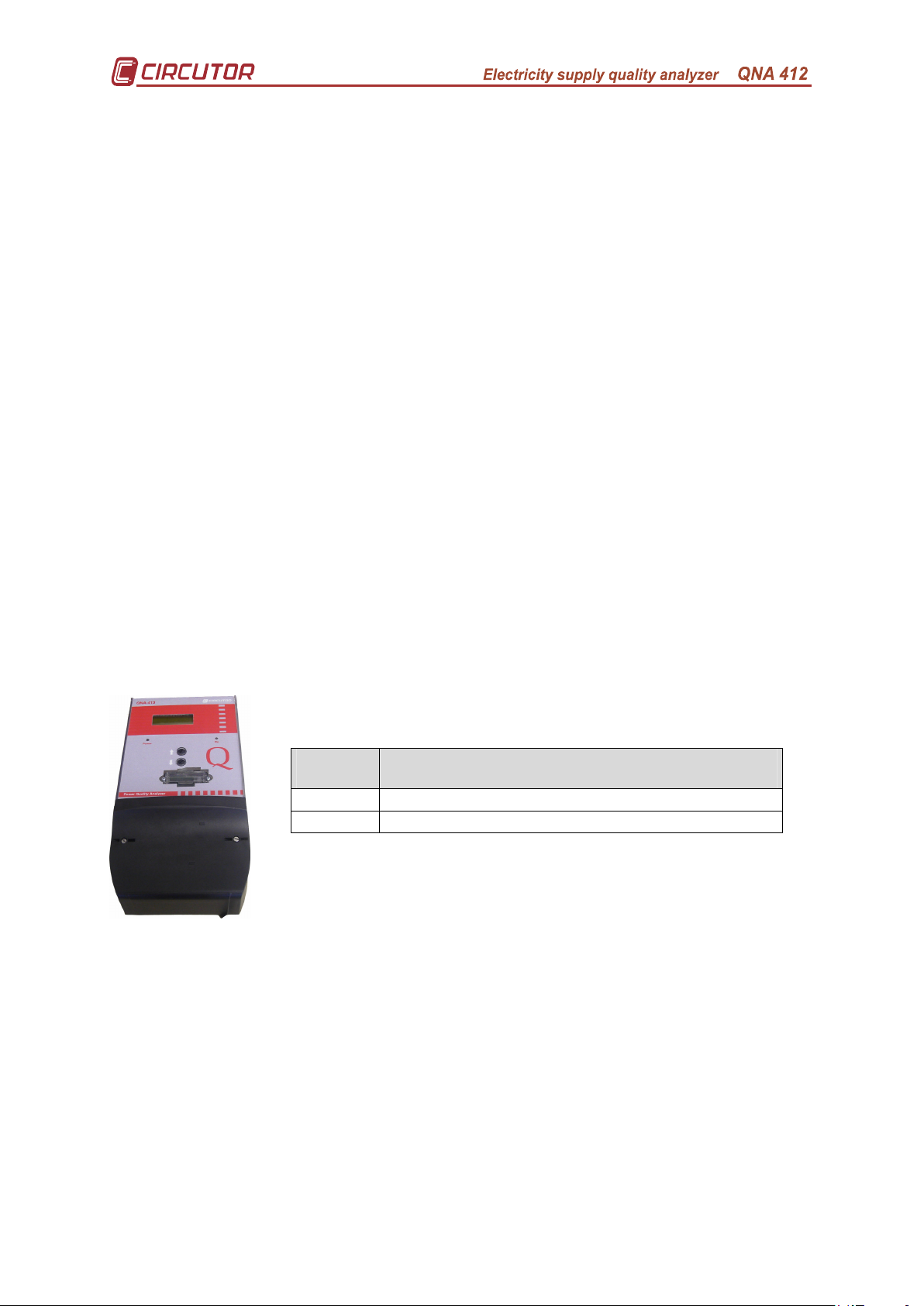
1.2.- QNA-412 models.
Code Model
Q20510 QNA – 412 RS485/RS232
Q20520 QNA – 412 GSM Free (SIM card not included)
Page no. 2
Page 4
1.3.- Safety advice.
For safety reasons it is essential that anyone installing or handling the
QNA-412 follows the usual safety procedures as well as the specific
warnings in this instruction manual.
If the equipment is used in a way not specified by the manufacturer,
the equipment's protection may be compromised.
When it is likely that a loss of protection has occurred (for example visible
damage) the equipment must be disconnected from the supply. In this event contact
a qualified service representative.
1.4.- Operating instructions.
The QNA-412 is programmable, measuring instrument offering a series of
options that may be selected using the set up menus.
Before installing the equipment and taking measurements carefully read
sections INSTALLATION, START-UP and SETTING for the QNA-412 analyzer.
Select the most suitable way of obtaining the required data.
It must be remembered that once the equipment is connected, the
terminals may be dangerous when touched and opening the covers or
removing pieces may access parts that are dangerous when touched. The
equipment must not be used until it is fully installed.
2.- GENERAL FEATURES.
The QNA-412 quality analyzer is specially designed equipment to control
electrical supply according to the IEC 61000-4-30 standard.
• Harmonics measurement according to IEC 61000-4-7.
• Flicker measurement according to IEC 61000-4-15.
• Measurement of the main electrical parameters.
− Voltage, current, power, PF....
− Voltage and Current harmonic distortion...
− Neutral Current and Neutral-Earth Voltage
• 4 quadrant measurement (Consumption and generation).
• Flicker measurement according to IEC 61000-4-15.
• High degree of protection under severe electrical conditions:
− With a broad supply voltage and measurement margin.
− High degree of overvoltage and transient protection.
• Option to connect to 3 and 4 wire systems.
• With a broad supply voltage margin: 63 – 520 V AC.
• Internal battery. The equipment can continue recording in the absence of
power supply voltage.
• 4 Mbyte internal memory where all parameters measured by the QNA-412
are stored.
• GSM / RS-232 / RS-485 communication. (According to model).
• Assembled in self-extinguishing casing in sizes and with fixing points in
accordance with the DIN 43857 standard.
Page no. 3
Page 5

2.1.- Basic features.
The QNA-412 quality analyzer is specially designed to analyse electrical
supply quality according to the specifications in the IEC 61000-4-30 standard.
It has 4 x 2V inputs (clamps) as well as the voltage inputs (isolated by
transformers). This means that as well as the supply quality calculations, the QNA412 can be used as a system analyzer.
Its outer design in accordance with DIN 43857 makes it ideal for locating in
any meter station cabinet.
Moreover, the large variety of models makes the QNA-412 adaptable to any
situation and any communication mode.
The equipment's internal battery allows it to take measurements in the event of
any loss of voltage (interruption or dip). It is guaranteed that the QNA-412 continues
operating if there is an interruption in the equipment's power supply.
The QNA-412 has three AC voltage inputs that lets it analyse voltage in the
three phases and the frequency of a predetermined system (quality of supply).
The QNA-412 uses a DSP to analyse the quality of electrical supply according
to the IEC 61000-4-30 standard. The DSP analyses all cycles of the three voltage
phases and checks whether any incident has occurred (dip, interruption,
overvoltage). It also calculates harmonics and flicker according to the IEC 61000-4-7
and 61000-4-15 standards respectively.
Thanks to its 2V inputs (2V/5A ratio), the QNA-412 can analyse the main
electrical parameters in the 4 quadrants (Consumption and generation).
The QNA also has a Neutral current input and another to measure NeutralEarth voltage. These parameters complete the information that the QNA supplies
when analysing the electrical system.
The QNA-412 has a 4 Mbyte internal memory where the quality parameters,
electrical parameters and incidents are recorded.
The QNA-412 memory has four types of files:
• *.STD: where the measured data (voltage, current, frequency, power,
energy, flicker, THD, unbalance...) is periodically stored.
• *.EVE: where any incident occurring to the QNA-412 is stored. (file
reading, Setup change, deleting from the memory, auxiliary power
supply on/off, battery off...).
• *.EVQ: Quality events file where incidents occurring with the electricity
supply are stored (interruptions, dips, overvoltages) plus supplementary
information about them (time when the incident occurred, length,
maximum/minimum voltage, average voltage, voltage prior to the
event).
• *.H24: where data is stored for statistical studies on the development of
the harmonics throughout a day.
Page no. 4
Page 6
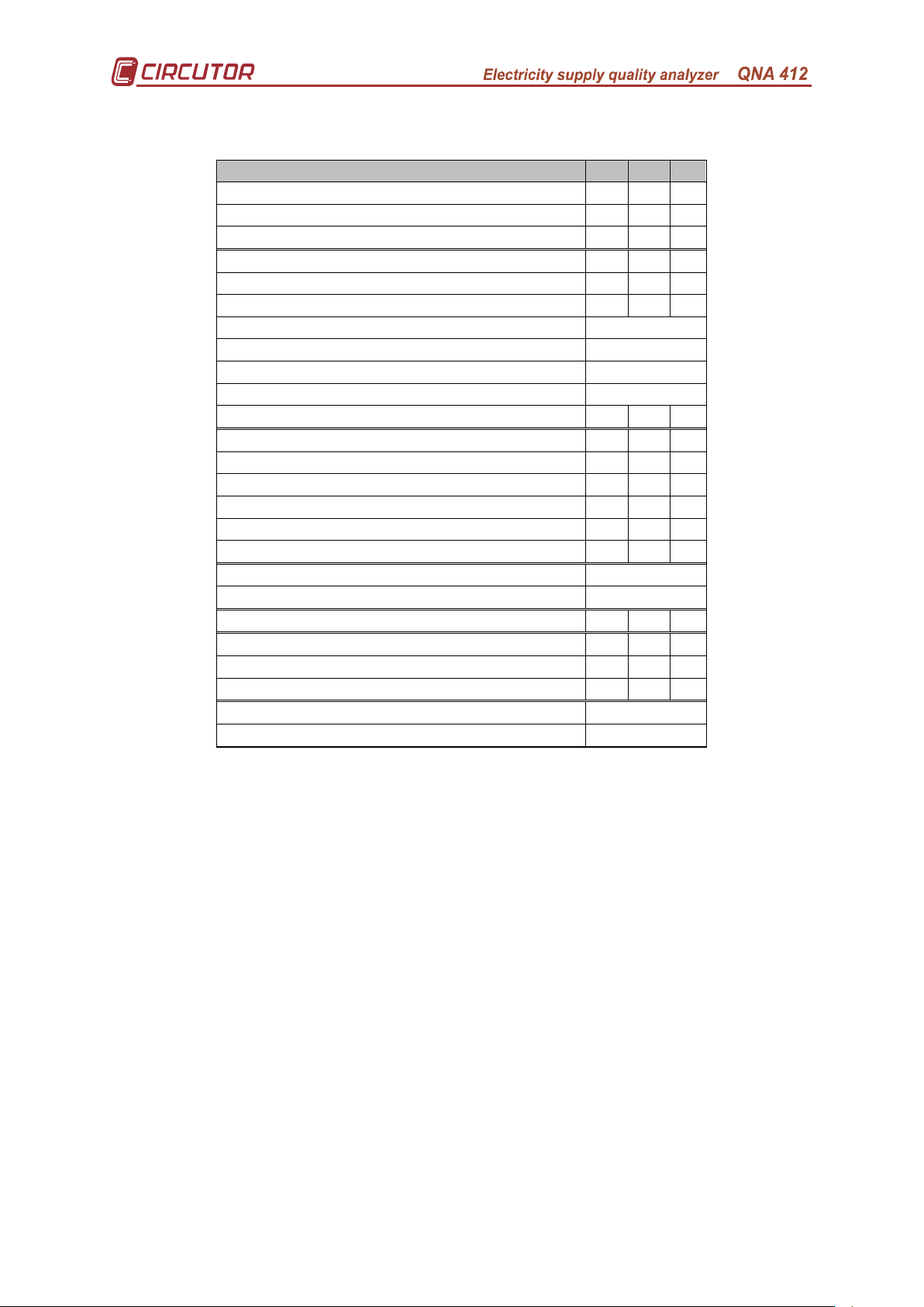
The parameters that the QNA-412 can measure are:
Parameter L1 L2 L3
Voltage X X X
Current (2V input) X X X
Frequency X
Active power X X X
Inductive reactive power X X X
Capacitive reactive power X X X
Apparent power X
Active energy X
Inductive reactive energy X
Capacitive active energy X
Power factor X X X
Voltage THD X X X
Current THD X X X
Harmonic Decomposition of voltage X X X
Harmonic Decomposition of current X X X
Voltage wave form X X X
Current wave form X X X
Neutral Current X
Earth neutral Voltage X
Flicker (PST) X X X
Dips X X X
Interruptions X X X
Overvoltage X X X
Unbalance X
Assymetry X
All these parameters are measured and recorded when the installation is
consuming or generating energy.
2.2.- Electrical characteristics.
Due to the fact that the QNA-412 is electrical supply quality recording
equipment, it must have a high degree of protection under severe electrical
conditions:
• High energy varistors for absorbing overvoltages and protecting the
equipment from costly repairs.
• Noise filter on the voltage input: Allows reliable measurements to be
obtained under the most adverse noise conditions.
• Power supply: transformers with higher power dispersal and isolation.
• Power supply from batteries allowing the QNA-412 to operate in the
absence of voltage supply.
• Isolating transformers to ensure input isolation.
Page no. 5
Page 7

3.- ANALYSIS MODES.
The QNA-412 series analyzers have different operating modes depending on
how they are set.
The most important operating functions are:
• Measurement and recording in the memory the main electrical supply quality
parameters (voltages, flicker, harmonics and unbalance).
• Measurement and recording in the memory the main electrical parameters
(voltages, currents, frequency, power, PF ...
• Current measurement for Neutral and Neutral-Earth Voltage.
• Setting a voltage threshold to define different events (dips, interruptions and
overvoltages). There is also the option to set a hysteresis value for all these
thresholds.
• The QNA-412 may be installed in both 3 wire and 4 wire systems. All quality
measurements will be made with reference to Neutral or between phases
depending on the selection.
• The QNA-412 may also be used to measure via voltage and current
transformers
4.- RECORDING IN THE MEMORY (automatically).
The QNA-412 has an internal clock, with date and time, to allow it to
automatically record electrical parameters as well as any incident that may occur.
The storage memory for the QNA-412 has four independent blocks reserved
for each type of file that it records. The following information is found in each of these
files:
• *.STD: where the measured data (voltage, current, frequency,
power, energy, flicker, THD, unbalance) is periodically stored.
• *.EVE: where any incident occurring to the QNA-412 is stored (file
reading, Setup change, deleting from the memory, auxiliary power
supply on/off, battery off...).
• *.EVQ: Quality events file where incidents occurring with the
electricity supply are stored (interruptions, dips, overvoltages...) plus
supplementary information on them (time when the incident
occurred, length, maximum/minimum voltage, average voltage,
voltage prior to the event).
• *.H24: where data is stored for statistical studies on the
development of the harmonics throughout a day.
The QNA-412 has a rotating storage memory. This means that if the memory
is full, new data obtained is stored in place of the oldest recordings. Therefore, if no
data is to be lost, files from the memory must be downloaded before it starts
recording over information that has not yet been downloaded.
Page no. 6
Page 8
isible damage), the
equipment must be disconnected from the power supply. In the event of
5.- INSTALLATION AND START-UP.
This manual has information and warnings that the user must
follow to ensure the safe operation of the equipment and to maintain it
in good condition in terms of safety.
If the equipment is used in a way not specified by the
manufacturer, the equipment's protection may be compromised. Opening covers or
removing parts with the equipment connected to the power supply, may access parts
which are dangerous when touched.
In the event of a possible loss in safety (e.g. v
this occurring, please contact a qualified service representative.
Page no. 7
Page 9
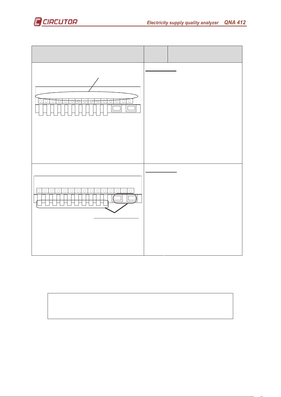
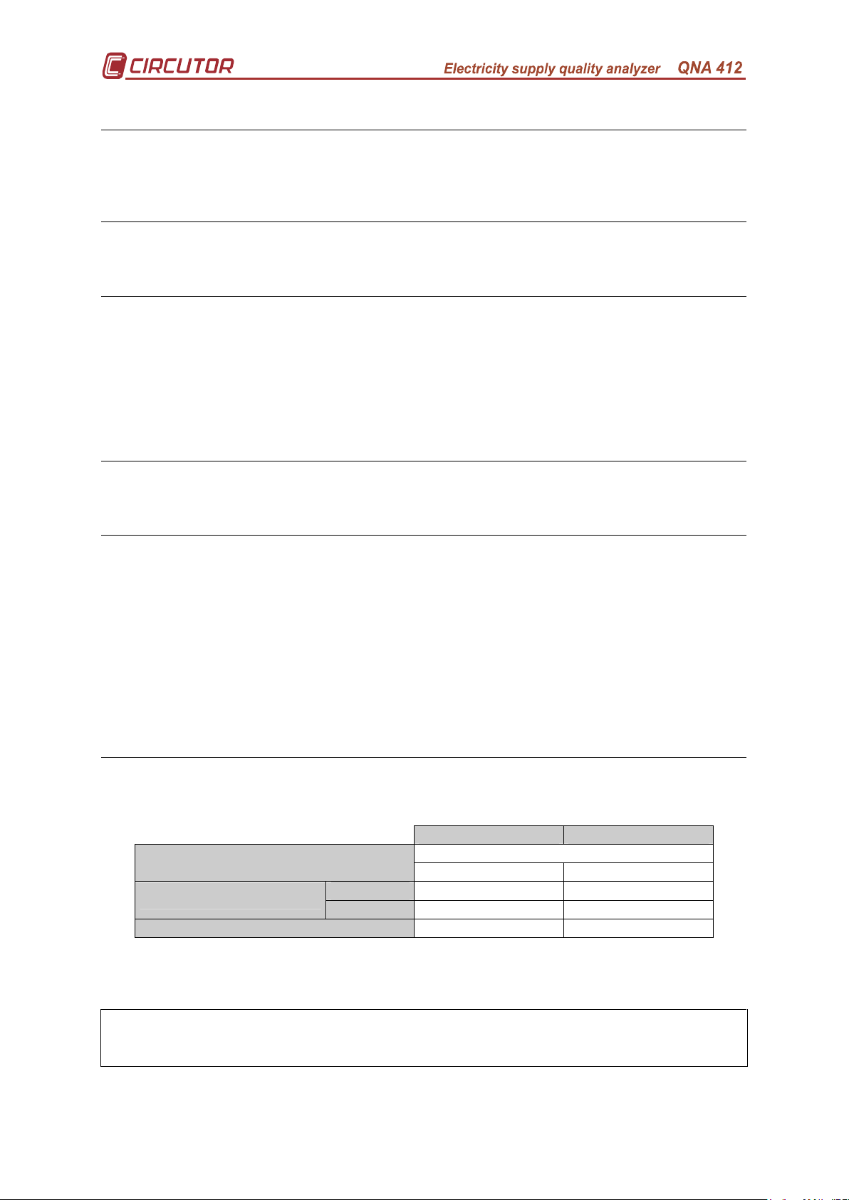
5.1.- Terminal ratio.
R1
35
Uppe r connection terminal
Lower c onnection termina l
21 22 24 3423 333026 3125
1 2 43 1165 7 8 9
27 3228 29
21 22 24 3423 333026 3125 3527 3228 29
1 2 4
3 1165 7 8 9
R2
R2
R1
Terminal
No.
Terminal Description
Upper board
21 VL1 measurement
22 Common L1
23 VL2 measurement
24 Common L12
25 VL3 measurement
26 Common L13
27 Neutral
28 Earth
29 Not connected
30 Not connected
31 Not connected
32 Not connected
33 Not connected
34 Not connected
35 Not connected
Lower board
1 Measured current IL1 S1
2 Measured current IL1 S2
3 Measured current IL2 S1
4 Measured current IL2 S2
5 Measured current IL3 S1
6 Measured current IL3 S2
7 Measured current Neutral S1
8 Measured current Neutral S2
9 Voltage input power supply
11 Voltage input power supply
R1 RS-232
R2 RS-485 / GSM Aerial
(According to model)
wire) or without Neutral (3 wire). Measurement only depends on the connection and
equipment setting.
The QNA-412 may be installed in either a three phase system with Neutral (4
Earthing is vital to the operation of the QNA-412's
protection.
Page no. 8
Page 10
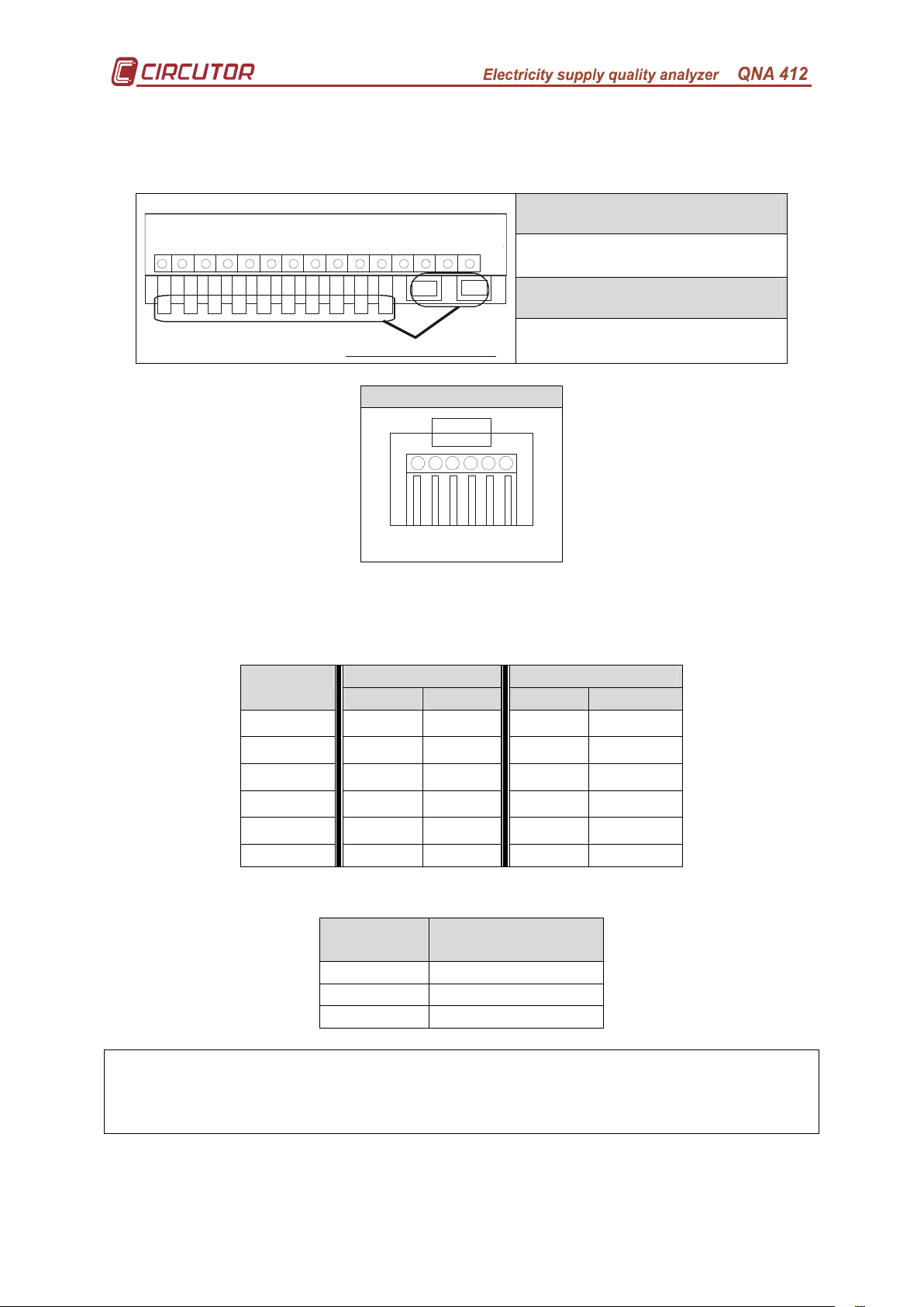
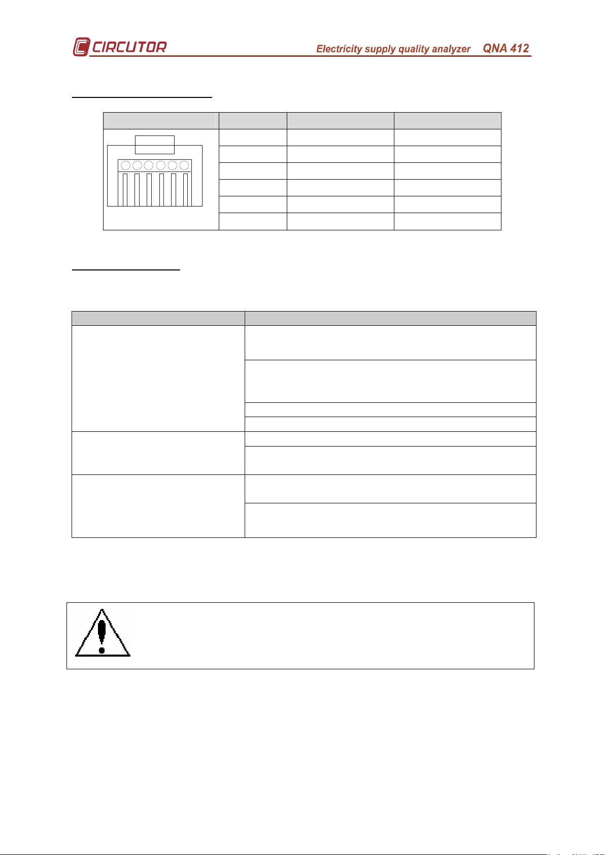
5.1.1.- Communications cables for RJ connectors.
Lower c onnection termina l
Front view
The use of the RJ connectors will vary according to the QNA model used.
Therefore:
QNA-412 RS232 / RS485
21 22 24 3423 333026 3125 3527 3228 29
R1 – RS-232 Communications
R2 – RS-485 Communications
R1
QNA-412 GSM / RS232
1 2 4
3 1165 7 8 9
R2
R1 – RS-232 Communications
R2 – GSM aerial
RJ Connector (QNA)
234 5
1 6
Below are diagrams of the most usual connections for the QNA-412 communications
cables:
• RS-232 connection to a PC or to an external modem:
PC External Modem QNA-412
DB9 DB25 DB9 DB25
1–DSR 5–GND 7–GND 5–GND 7–GND
2–Rx 3–Tx 2–Tx 2–Rx 3–Rx
3–TX 2–Rx 3–Rx 3–Tx 2–Tx
4–CTS 7–RTS 4–RTS 8–CTS 5–CTS
5–RTS 8–CTS 5–CTS 7–RTS 4–RTS
6–GND 5–GND 7–GND 5–GND 7–GND
• RS-485:
QNA-412 RS-232/485 (DB9)
Converter
2–Tx/Rx(-) 2–Tx/Rx (-)
3–Tx/Rx(+) 1–Tx/Rx (+)
6–GND 5–GND
To communicate with a QNA-412-GSM via a mobile telephone, the RS232 communications cable must not be connected at any time. If it is detected
that the RS232 cable is connected, any modem operation will be cancelled.
Page no. 9
Page 11

5.2.- QNA-412 analyzer start up.
Before connecting the equipment to the mains
please bear in mind the
following points:
1) Supply system voltage:
Voltage: 63 – 520 V AC.
Frequency: 50... 60 Hz.
2) Earth: The equipment must have the earthing cable connected. If it is not
attached, some of the equipment's protection will become ineffective.
3) Maximum current in the voltage measurement circuit: 500 V AC. between phase
and common:
4 wire configuration: 500 V AC Neutral-phase / 866 V AC. phase-phase.
3 wire configuration: 500 V AC. phase-phase.
4) Maximum measurement current: According to CLAMPS USED. In / 2 V AC.
5) Maximum measurement current: According to CLAMPS USED. In / 2 V AC.
6) Equipment consumption: 16 W.
7) Operating conditions:
• Operating temperature: 0º to 50º C.
• Operating humidity: 25% to 75 % RH.
8) Safety: Designed for category III installations according to EN 61010.
Points to check during installation:
8) Check that the earth has been connected to avoid interference to the equipment.
Not attaching the earth reduces the effectiveness of the QNA-412's protection.
9) Check the power measurements and their sign (Check the polarity of the current
transformers).
10) Check the QNA-412 analyzer setting.
Please note
A symptom of poor installation or wrong setting is the measurements flashing
on the display. The causes may be:
− The equipment has detected an event. This may mean that there has
actually been an event on the line (correct installation) or that the pre-set
nominal voltage does not match that of the system.
− If dashes appear on the balance screen: it means that the sequence of
the phase turn is wrong.
Page no. 10
Page 12

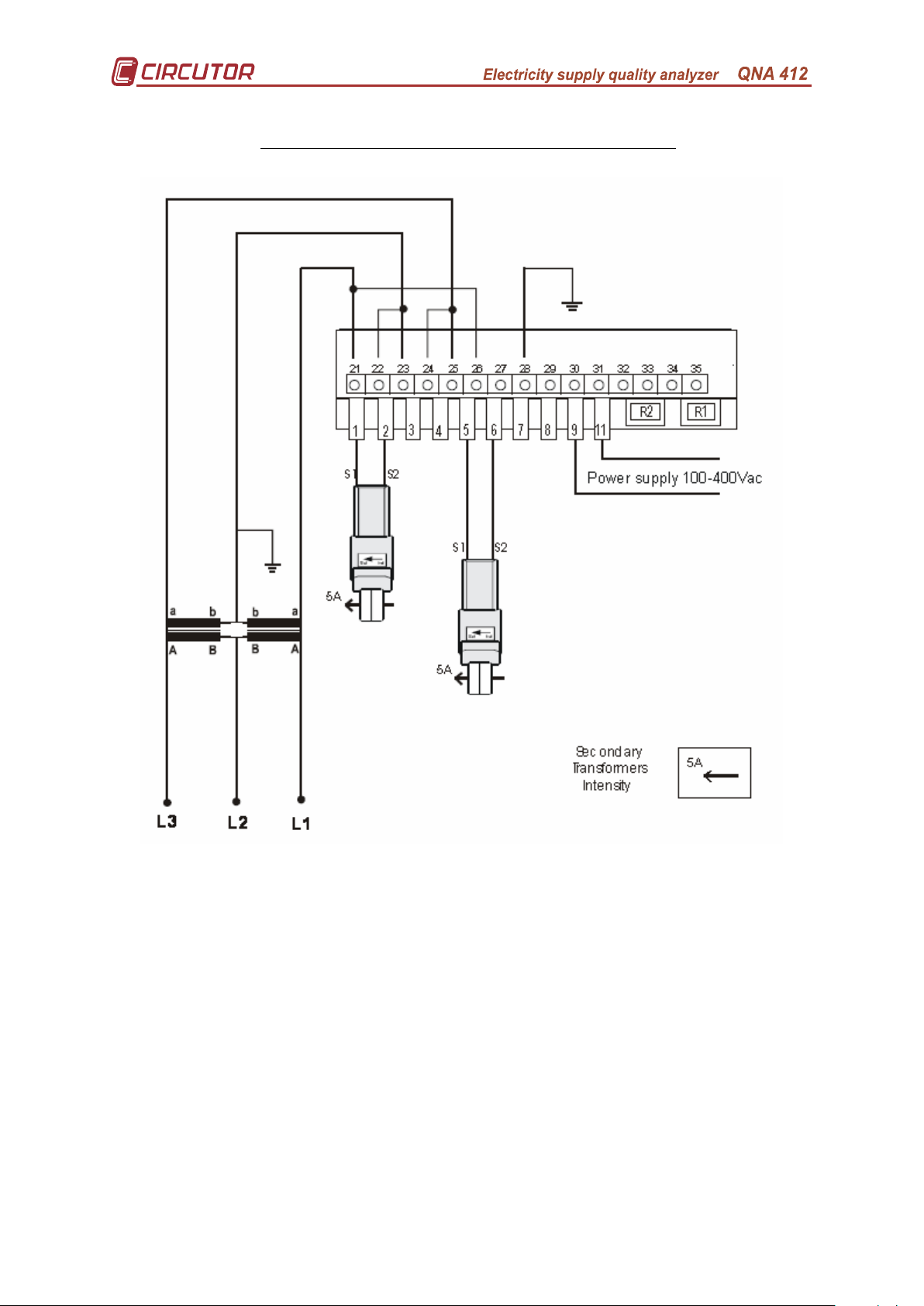
Connection diagram for the QNA-412.
5.3.-
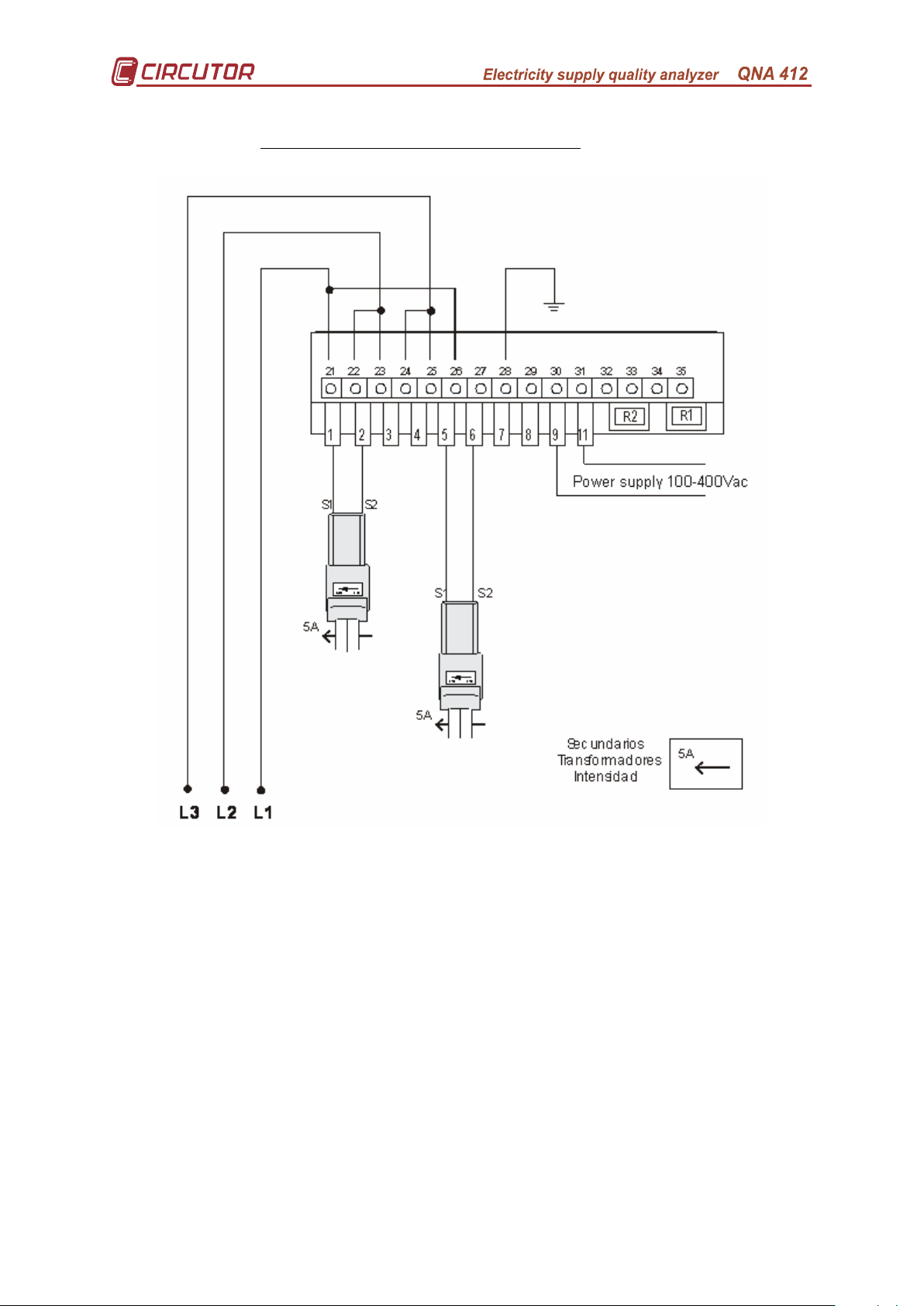
5.3.1.- 4 wire three phase systems.
5.3.1.1.- Direct voltage + three clamps
(L1-L2-L3):
Page no. 11
Page 13

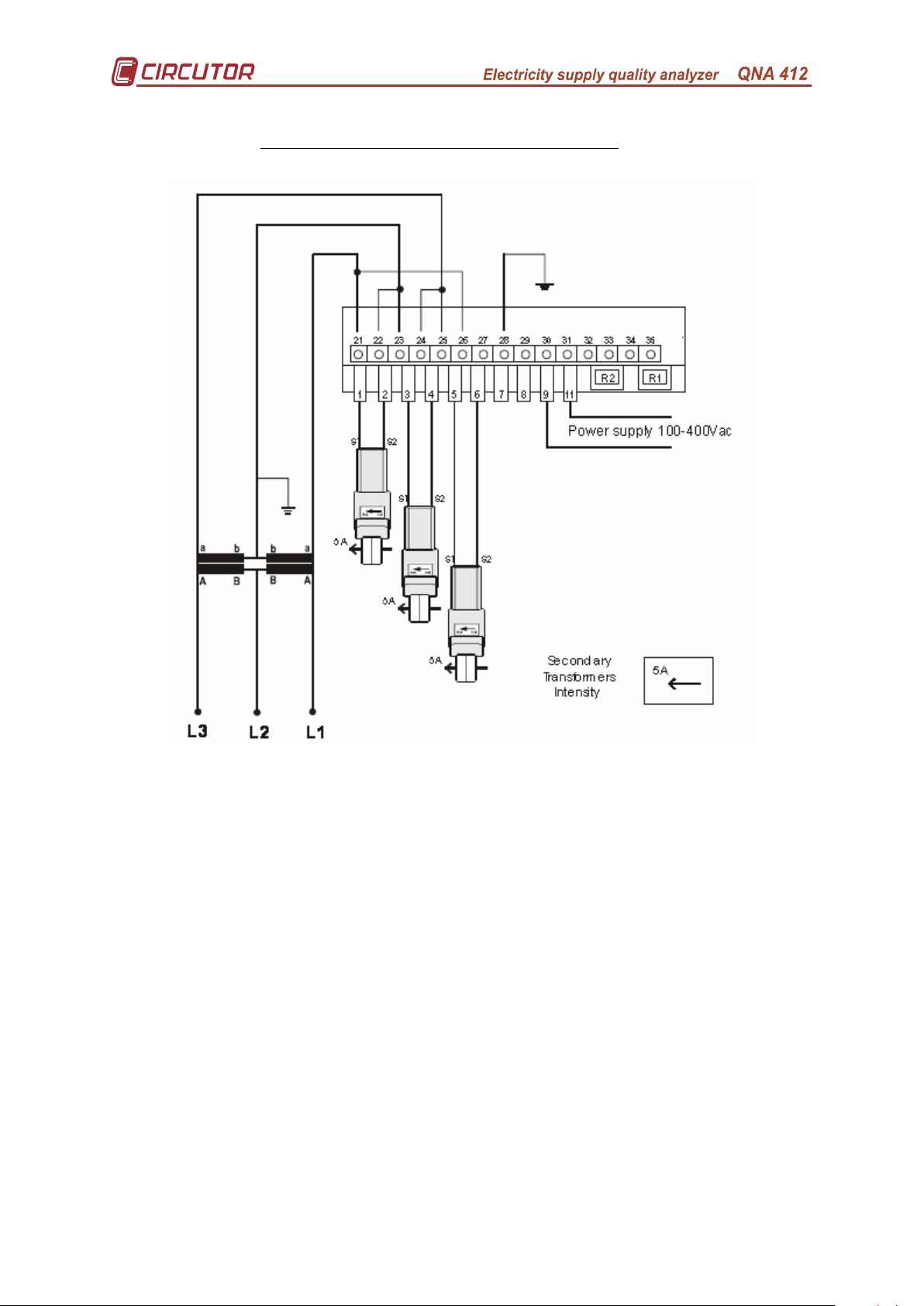
5.3.1.2.- Three voltage transformers and three clamps
(L1-L2-L3):
Page no. 12
Page 14

5.3.2.- 3 wire three phase systems.
5.3.2.1.- Direct voltage and three clamps
Page no. 13
Page 15
5.3.2.2.- Direct voltage and two clamps (ARON)
Page no. 14
Page 16
5.3.2.3.- Two voltage transformers and three clamps
Page no. 15
Page 17
5.3.2.4.- Two voltage transformers and two clamps (ARON)
Page no. 16
Page 18
6.- THE QNA-412 ANALYZER BATTERY.
The equipment has a battery for keeping the analyzer working and able to
properly record in the event of any incident occurring. The battery allows the
equipment to continue operating for 2-4 hours without mains supply. The time during
which the analyzer is to continue recording in the absence of mains supply is
programmable. In this way the QNA-412's battery can be saved and can detect
intermittent interruptions regardless of the time it takes to recharge.
The fact that the battery ensures 4 hours of operation is extremely important
because the equipment can continue recording and operating correctly in the event
of multiple and lengthy interruptions.
The battery always recharges when the analyzer
is connected to the system.
The QNA-412 Analyzer has an intelligent energy charge system This means that
the equipment is continuously monitoring the battery levels and if the charge level is
on maximum, it stops charging. This way the battery life is extended.
7.- OPERATION.
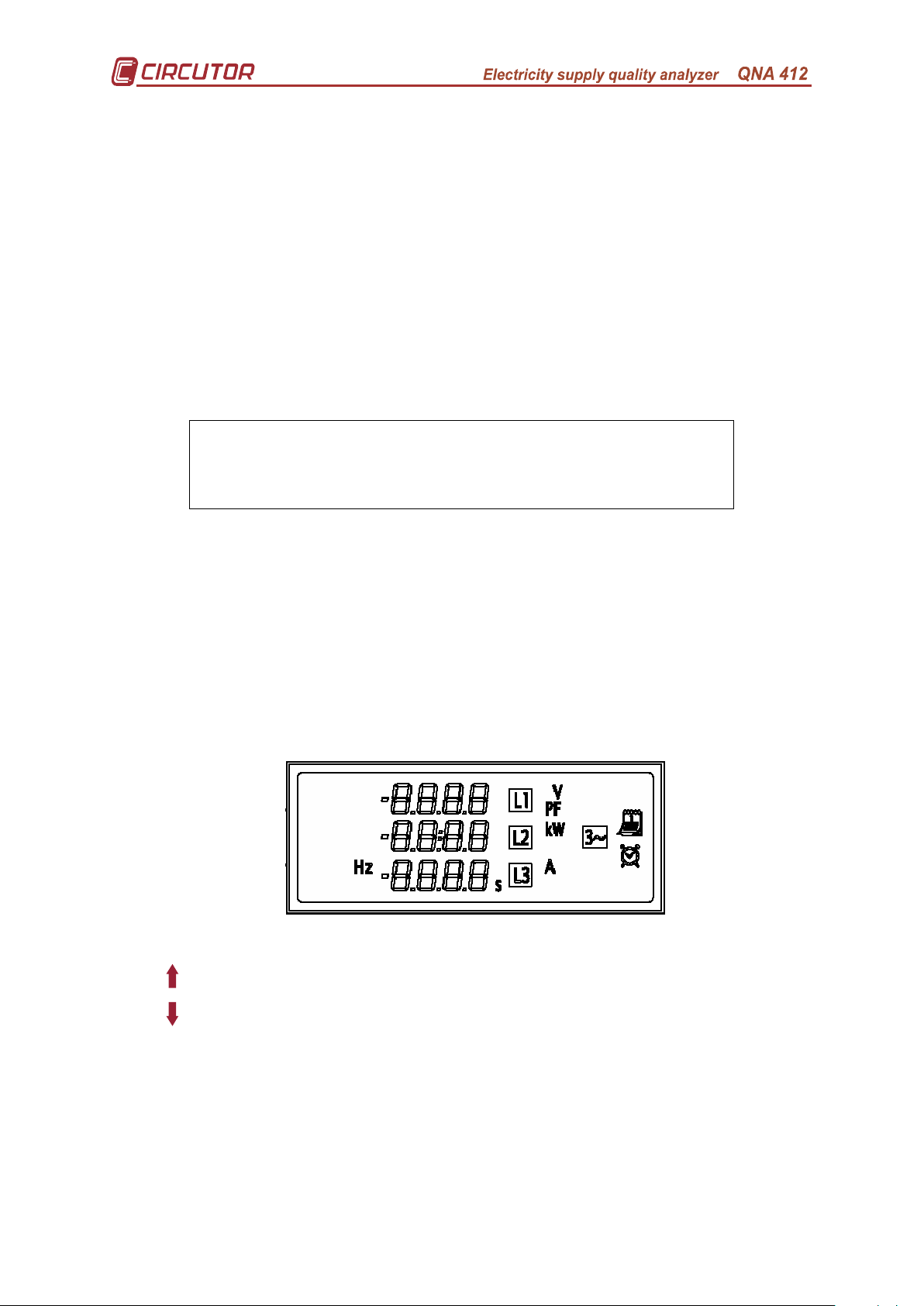
7.1.- Display and buttons.
The QNA-412 has a display where the information the QNA is collecting can be
displayed using the buttons.
The functions of the buttons on the QNA-412 are:
− (Next screen): Moves on to the next display screen.
− (Previous screen): Displays the previous data screen.
Page no. 17
Page 19

7.2.- Start-up.
A screen identifying the equipment will appear on the display when first
starting the QNA-412.
After a few seconds the first screen will appear where the voltages that the
QNA is measuring in the three phases will be displayed.
Using the and different display screens can be browsed.
7.3.- Display screens.
The different display screens on the QNA-412 are:
Voltage measured in the system.
Current measured in the system.
Active power.
kw not flashing = kW
kw flashing = MW
Power factor.
Unbalance coefficient.
Asymmetry coefficient.
Frequency.
Date
Day / month
Year
Clock
Hours / minutes
Seconds
Neutral-Earth Voltage.
Neutral Current.
Page no. 18
Page 20
Comments
There are several symptoms that may detect poor installation or setting of the
QNA-412:
• The voltage measurements are flashing on the display. The causes may be:
− The equipment has detected an event. This may mean that there has
actually been an event in the line (correct installation) or that the pre-set
nominal voltage does not match that of the system.
− If the balance screen displays dashes: It means that the phase turn
sequence is wrong.
• Power screens with a minus sign:
− The installation is generating energy. Or actually, energy is being
generated or the current transformers are installed backwards.
− The PF values are wrong. Check the voltage phases and current
connection. The voltage and current phase do not correspond to that
connected to the QNA.
8.- SETTING THE QNA-412.
The QNA-412 is always set via a PC.
The operation of the QNA-412 analyzer will depend on the setting of the
equipment. There are two types of Set-up:
• Programming Set-up: This will define the QNA-412 analyzer's operating mode.
• File setup: This will define the variables that the QNA-412 is to record in its
internal memory
8.1.- Programming Set-up for the QNA-412.
There is a complete series of parameters that may be set in the analyzer:
8.1.1.- Voltage transformation ratio.
The QNA-412 system analyzer has the option to measure voltage via
transformers.
• Voltage primary / Voltage secondary: The voltage transformer ratio via
which the measurement shall be taken can be set. Where direct
measurements are to be made, this must be set as1/1.
• Current primary: The current transformer primary used for measuring
current can be set.
• Neutral current primary: The current transformer primary used for
measuring Neutral current can be set.
Page no. 19
Page 21
8.1.2.- Features of the system.
• Nominal voltage: This is the nominal voltage measured by the analyzer.
For 3 wire settings the compound voltage must be set (e.g. 400 V), and for
4 wire, the simple voltage (e.g. 230 V). If measurement is done via voltage
transformers, the nominal voltage that is to be set must refer to the
secondary (e.g. 63.5 V). This value is vital to the proper working of event
recording.
• Nominal frequency: Nominal frequency of the system being analyzed.
This parameter is necessary for calculating the effective value of the signal
in extreme quality systems.
• 3 wire / 4 wire: The QNA-412 is designed to operate in installations with
Neutral (4 wire) or installations without Neutral (3 wire). For this, the type of
connection will be defined. This point is very important because it will
measure events depending on how it is set.
• Type of circuit: If measurement is being done via three current sockets,
the type of measurement circuit must be set as three phase. The QNA has
the option to measure current with the Aron system in installations that do
not have neutral (3 wire). This means that only two current sockets are
used for the measurements.
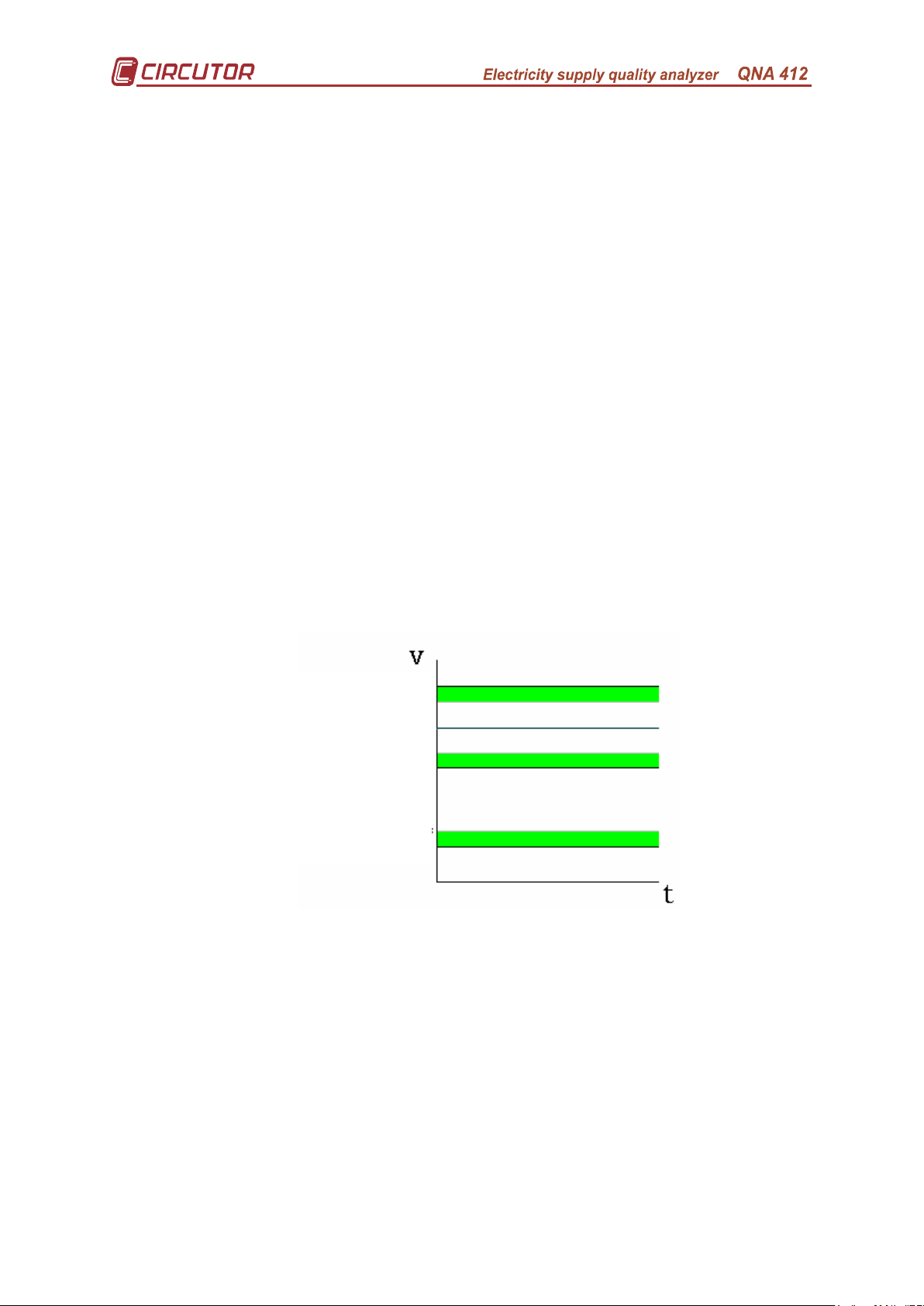
8.1.3.- Quality Parameters.
In order to calculate the supply quality, the voltage levels above which
an event will have deemed to occurred have to be set.
Overvoltages
Hysteresis
Nominal Voltage
Hysteresis
Dip / Short cut-off
Hysteresis
Interruption / Cut
Therefore it is necessary to define the following points
• % Overvoltage threshold: Detecting overvoltage will depend on the value
that is set in this section. For every half cycle that its effective value exceeds
this defined value (% above nominal voltage) it will be considered to be
overvoltage. The events file (EVQ) will record each time this value is
exceeded, showing the phase, maximum voltage recorded, average voltage,
voltage prior to the event and the time when this threshold was exceeded.
Page no. 20
Page 22

• Overvoltage hysteresis: An overvoltage hysteresis is to be defined so that
the voltage at the start of the overvoltage is not the same as the voltage at the
end. Therefore an overvoltage starts when the overvoltage threshold is
exceeded and ends when it is below the value defined by difference between
the overvoltage threshold and the overvoltage hysteresis.
• % Dip threshold: Detecting a dip will depend on the value that is set in this
section. For every half cycle that its effective value exceeds this defined value
(% above nominal voltage) it will be considered to be a dip. The events file
(EVQ) will record each time this value is not exceeded, showing the minimum
voltage recorded, average voltage, voltage prior to the event and the time
when this threshold was not exceeded.
• Dip hysteresis: A dip hysteresis is to be defined so that the voltage at the
start of the dip is not the same as the voltage at the end. Therefore a dip starts
when the dip threshold is not exceeded and ends when it is above the value
defined by adding the dip threshold and the dip hysteresis.
• % Interruption voltage threshold: This is defined as power off (no voltage,
Interruption) by voltage dropping below a fixed value (% above nominal
voltage). The events file (EVQ) will record each time this value is not
exceeded, showing the minimum voltage recorded, average voltage, voltage
prior to the event and the time when this threshold was not exceeded.
• Interruption Hysteresis: An interruption hysteresis is to be defined so that
the voltage at the start of the interruption is not the same as the voltage at the
end. Therefore an interruption starts when the interruption threshold is not
exceeded and ends when it is above the value defined by adding the
interruption threshold and the interruption hysteresis.
• Time of recording the STD file. This is the section of the memory for this file
and is expressed in days. The value cannot be changed. It will depend on the
period of recording and the capacity defined in the other files.
• Number of recordings for the EVE file. This is the section of the memory for
the events file and states the number of events.
• Number of recordings for the EVQ file. This is the section of the memory for
the events file and states the number of events.
• Size of H24 recording file: Indicates the size of the H24 file.
Time of recording STD file (*)
Number of recordings
Size of H24 file (in Kb):
(*) The STD file has been calculated with a recording period of 10 minutes and the
(**) Minimum configurable values.
EVE file
EVQ file
variables of the STD file as a default.
Page no. 21
Default Maximum STD
(Value Calculated – Not configurable)
34 days 5 hours 92 days 2 hours
1365 682
2554 5626
264 (33 days) 8 (1 day)
Page 23

8.1.4.- Information to be taken into account in the recording of the periodic
values.
There are a series of points to precisely define which information must be
used to calculate the recordings.
Therefore the following may be defined:
• Description of the Measurement point: This is only an identification field
used by the user.
• Comment: This is only an identification field used by the user.
• Recording Period: All electrical parameters will be recorded at the end of the
pre-set time (those parameters selected only). The average values obtained
during that period of time will be recorded. As default the recording period is
set at 10 Minutes. This value may range from 1 minute to 2 hours.
• Integrating blocks of 10 cycles with events (all except voltage): (Affects
the .STD file only). While the average voltage, flicker, harmonics are being
calculated, it is possible that an event occurs (overvoltage, dip, etc.). The QNA
allows (or does not allow) the 10 cycle block where such an event occurred to
be added to the integration. When this option is deactivated ("No"), the 10
cycle block will only be added to the average voltage.
• Integrating blocks of 10 cycles with events (voltage): (Affects the STD file
only). While the average voltage is being calculated, it is possible that an
event occurs (overvoltage, dip, etc.). The QNA allows (or does not allow) the
10 cycle block (this may be one or more depending on the length of the event)
where such an event occurred to be added to the integration. When this option
is deactivated ("No"), the 10 cycle block will only be removed and therefore not
added to the integration of this recording period. This option does not affect
the other parameters.
• Recording period: (Affects the STD file only). This is the period when the
averaged values are stored.
• Type of date: (Affects the STD file only). The date/time when the recorded
data in a recording is to be saved may be selected (Affects the STD file only).
This may be at the start or end of the recording.
• Battery disconnection time: The QNA may set the time for self
disconnecting the equipment when there is no mains supply. This means that
the battery is not completely run down when there are problems with electricity
supply. A typical value is about 15-30 mins.
8.2.- Variables to Record.
The QNA-412 stores all quality parameter recordings in its internal memory.
Data is stored in three files:
Page no. 22
Page 24

8.2.1.- Standard File (STD).
The Standard File (STD) is used to store all those parameters that are
periodically stored.
With regard to the recording period preset in the QNA-412, recordings will be
made with the following electrical parameters (according to selection):
Parameter L1 L2 L3
Voltage (Neutral phase or Phase-Phase) X X X STD
Current X X X STD
Frequency X STD
Apparent power X STD
Consumption
Active power X X X STD
Inductive reactive power X X X STD
Capacitive reactive power X X X STD
Power factor X X X STD
Active energy X STD
Inductive reactive energy X STD
Capacitive reactive energy X STD
Generation
Active power X X X STD
Inductive reactive power X X X STD
Capacitive reactive power X X X STD
Power factor X X X STD
Active energy X STD
Inductive reactive energy X STD
Capacitive reactive energy X STD
Neutral Current X STD
Neutral-Earth Voltage X STD
Harmonics
THD voltage X X X STD
THD current X X X STD
Voltage harmonic decomposition
X X X STD
(Option to select any harmonic 2-40)
Current harmonic decomposition
X X X STD
(Option to select any harmonic 2-40)
Wave Forms (V, I) X STD
Flicker (PST) X X X STD
Quality
Dips X X X EVQ
Interruptions X X X EVQ
Overvoltage X X X EVQ
Unbalance
Unbalance X STD
Asymmetry X STD
File
* In the STD file all average values of the parameters are recorded.
Page no. 23
Page 25

Flicker:
• Pst: The QNA-412 records the value of Flicker (Pst) obtained during the
recording period. The Plt value is calculated by the PC analysis software.
Harmonics:
Harmonic Distortion: The QNA-412 will calculate and record the average
value of the harmonic distortion for voltage and current that has been
detected in the analysed system.
Harmonic Decomposition: The QNA-412 will calculate and record the
average value of the rate of individual harmonic distortion for each of the
voltage and current harmonics in the analysed system (up to harmonic 40).
(Decomposition of each of the blocks of 10 cycles that have been
integrated within a recording period).
Wave Forms:
Voltage: One cycle record of the voltage signal's wave form at the time of
ending the recording.
Current: One cycle record of the current signal's wave form at the time of
ending the recording.
Unbalance:
Coefficient of asymmetry: ratio between homopolar and direct voltage.
Coefficient of unbalance: ratio between inverse and direct voltage.
8.2.2.- EVENTS file (EVQ).
The different events detected in the analysed electrical system are stored in
this file. The following information is stored for each of the events:
Event Date: This shows the time when the event occurred. This value is
obtained with an accuracy of one Cycle
Type of event: This is stored if the detected event is an interruption, dip or
overvoltage. These events are defined according to the setting for the QNA-412. The
type of event also identifies the phase in which it occurred.
Duration of the Event: How long the event lasted in milliseconds.
Maximum / minimum voltage of the Event: In the event of an interruption or
dip the minimum voltage RMS½ value (*) obtained during the event will be stored. In
the event of overvoltage the maximum value will be stored.
Average voltage of the event: Average voltage RMS½ value (*) obtained
during the recorded event.
Voltage prior to the event: The voltage RMS½ value (*) prior to the event is
stored.
(*) value RMS½ cycle: effective value of one complete cycle, updated every half
cycle.
Page no. 24
Page 26

8.2.3.- Incidents File (EVE).
This file automatically stores the type and time of the incident that has occurred.
The QNA-412 is able to detect and record the following incidents, among others:
Battery Off: This will show the time when the QNA-412 stopped working. This
time depends on the value pre-set, because the equipment operates on an internal
battery in the event of a fault with the auxiliary power supply.
Auxiliary power supply On: This indicates the time when the power supply
was connected to the QNA-412.
Auxiliary power supply Off: This shows the time when the power supply to
the QNA-412 was interrupted. At this point power is supplied from the battery.
Setup Changed: This records the time when any change was made to the
equipment's Setup.
Memory Format: The time when the user decided to start the internal memory
on the QNA-412.
Internal memory format forced: There is an error with the internal memory
and the QNA-412 has automatically started all of the memory.
Deleting a file: The time when the user has deleted a file from the internal
memory of the QNA-412. If the first piece of information that appears in the EVE file
is file deleted, this means that the deleted file was an events file.
Changing the time: The date or the time on the equipment has been
changed. It is important to detect this type of event because on many occasions time
gaps between measurements are due to time changes.
Page no. 25
Page 27
9.- TECHNICAL FEATURES.
Power supply:
Supply voltage: Independent from Measurement 63 – 520 V AC.
Frequency: 50...60 Hz.
Consumption: 16 W
Operating temperature: 0...50 ºC
Auxiliary power supply:
Battery: Ni-M-H
Independent operating life: 4 h continuous working
(For soft
this cannot exceed a time of 1 hour to extend battery life)
Voltage measurement:
Measurement Circuit: 3 or 4 wire configuration (Using external connection)
Measurement range: 0 to 500 V AC. (between phase and common).
Connection for 4 wire systems: 0 to 550 V AC. (phase-neutral).
0 to 952 V AC. (between phases).
Connection for 3 wire systems: 0 to 550 V AC. (between phases).
Changing the scale : Automatic.
Other voltages : Via measurement transformers.
Frequency :
42.5 - 57.5 for 50Hz
/
51 - 69 for 60Hz.
Current measurement:
Measurement range : ... /5A (according to transformers used).
Maximum current : 1.2 In.
Changing the scale : Automatic.
Accuracy:
Voltage: 0.1 % of nominal. (Class A according to IEC 61000-4-30)
Current: 0.1 % of nominal. (Class A according to IEC 61000-4-30)
Power: 0.2 % of nominal
Unbalance: ± 0.15% (Class A as per IEC 1000-4-30)
Flicker: <5% as per IEC 61000-4-15 (Class A according to IEC 61000-4-30)
Harmonics: Class I as per IEC 61000-4-7 (Class A according to IEC 61000-4-30)
Accuracy given with the following measuring conditions:
- Exclusion on errors made by voltage transformers.
- Temperature range : 5 to 45 ºC.
- Measurement margin : between 5 % and 100 %.
Memory:
Memory size: 4 Mbytes.
Memory Configuration: Rotating.
Time of recording STD file (*)
Number of recordings
Size of H24 file (in Kb)
(*) The STD file has been calculated with a recording period of 10 minutes and the
(**) Minimum configurable values.
EVE file
EVQ file
variables as a default for the STD file.
Default Maximum STD
(Value Calculated – Not configurable)
34 days 5 hours 92 days 2 hours
1365 682**
2554 2042**
264 (33 days) 8 (1 day)**
Processor:
Sampling frequency : 5120 k samples/second for each channel (6 channels).
Converter : 16 bits (Sigma delta).
Page no. 26
Page 28

Assembly Features:
176
9
4
.
5
3
2
7
Casing: According to DIN 43859 standard
Sizes: According to DIN 43857 Standard
Weight: 2.3 Kg
STANDARDS
Quality: IEC 61000-4-30.
Harmonics: IEC 61000-4-7.
Flicker: IEC 61000-4-15.
Other standards
EN 60664, EN 61010, EN 61036, VDE 110, UL 94.
ELECTROMAGNETIC EMISSION.
− EN 61000-3-2 (1995), Harmonics.
− EN 61000-3-3 (1995), Voltage fluctuations.
− EN 50081-2 (1993), Industrial emission.
ELECTROMAGNETIC IMMUNITY.
− EN 50082-2 (1995), Industrial immunity.
− EN 50082-1 (1997), Domestic immunity.
__________________________________________
− EN 55011 (1994): Conducted (EN 55022 - Class B).
− EN 55011 (1994): Radiated (EN 55022 - Class A).
− EN 61000-4-2 (1995), Electrostatic discharge.
− ENV 50140 (1993), RF EM radiated fields.
− EN 61000-4-4 (1995), Rapid transients bursts.
− ENV 50141 (1993), RF in common mode.
− EN 61000-4-8 (1995), Magnetic field at 50 Hz.
− EN 61000-4-5 (1995), Shock wave.
− EN 61000-4-11 (1994),Power supply interruptions.
Page no. 27
Page 29

10.- SAFETY ADVICE.
The installation rules in the previous sections (INSTALLATION
AND START UP, FORMS OF INSTALLATION AND TECHNICAL
FEATURES) have to be borne in mind.
When the equipment is connected, the terminals can be
dangerous when touched. Opening covers or removing objects may access parts
that are dangerous when touched. This equipment has been designed to conform to
the IEC-348 standard and is supplied in proper working order.
11.- MAINTENANCE.
The QNA-412 does not require special maintenance. Any adjustment,
maintenance or repair to the open equipment is to be avoided. If it cannot be avoided
it must be undertaken by someone qualified and well informed of the necessary
action.
Before any connection, replacement, maintenance or repair the equipment
must be disconnected from any power supply.
When the equipment or its protection is suspected to be faulty, it must be
taken out of service and any accidental connection avoided.
The equipment is designed to be changed quickly in the event of any
breakdown.
12.- TECHNICAL SERVICE.
In the event of any equipment failure or any operational queries please contact
the technical service of CIRCUTOR S.A.
CIRCUTOR S.A. - After sales service.
Vial Sant Jordi, s/n
08232 - Viladecavalls.
Tel. - (+34) 93 745 29 00
Fax - (+34) 93 745 29 14
E-mail - central@circutor.es
Page no. 28
Page 30

Modem A
Modem B
A. Appendix: Communications with QNA-412 connected to an External
modem.
One of the most usual configurations for the QNA-412 is for it to be connected
with an external modem.
To connect it and before its definitive start up, it must be remembered that
both Modems have to establish the correct form of communication. To do so, a
minimal setting for the modem making the call and the modem connected to the QNA
has to be made.
To do this setting, the Hyperterminal program on Windows or equivalent must
be used. The configuration for the modem is:
• MODEM A (PC):
AT&F Default configuration.
AT&D2 Activates the operations of the DTR Data Terminal Ready.
AT&S0 Leave the DSR active Data Set Ready.
AT&W0 Store the configuration.
• MODEM B (QNA-412):
AT& F Default configuration.
AT&D0 Override the DTR.
AT&K3 Deactivate data compression.
AT&R1 The modem ignores the RTS.
AT&N6 Increase the speed of the modem to 9600 bps.
ATS0=1 Activate the modem so that responds to the first ring.
AT& W0 Store the configuration.
The AT commands here may be varied according to the type of modem.
To correctly configure, consult the manuals for the installed equipment.
Page no. 29
Page 31
Communications cables
Front view
working properly using a Hyperterminal program or
hat the command for the modem to answer
RJ Connector
4
2
1 6
5
3
QNA-412 Modem (DB9) Modem (DB25)
1–DSR 5–GND 7–GND
2–Rx 2–Rx 3–Rx
3–TX 3–Tx 2–Tx
4–CTS 8–CTS 5–CTS
5–RTS 7–RTS 4–RTS
6–GND 5–GND 7–GND
Possible problems
The majority of problems that may be encountered with this configuration
are caused by the Modem.
Problem Solution
Modem A is not calling
Check that the computer port being used is the one
that is connected to the Modem.
Verify that the computer port and Modem port are
similar.
Verify the Modem connections.
Verify the telephone line and its connection.
Check that the modem is on. Modem B is not responding.
Check t
on the first ring has been made (ATS0=1).
Modem B answers but does
not receive a response from
the equipment.
Verify that the port being used is the R1 and that the
cable is connected.
Verify the QNA communications port setting. Verify
that it is 9600 bauds.
Operation has been checked to be correct for the following types of Modems:
VAYRIS, MULTITECH, WESTERMO and U.S. ROBOTICS.
The local modem (A) cannot make a call via a telephone
switchboard. It must be a direct line.
Page no. 30
Page 32
Front view
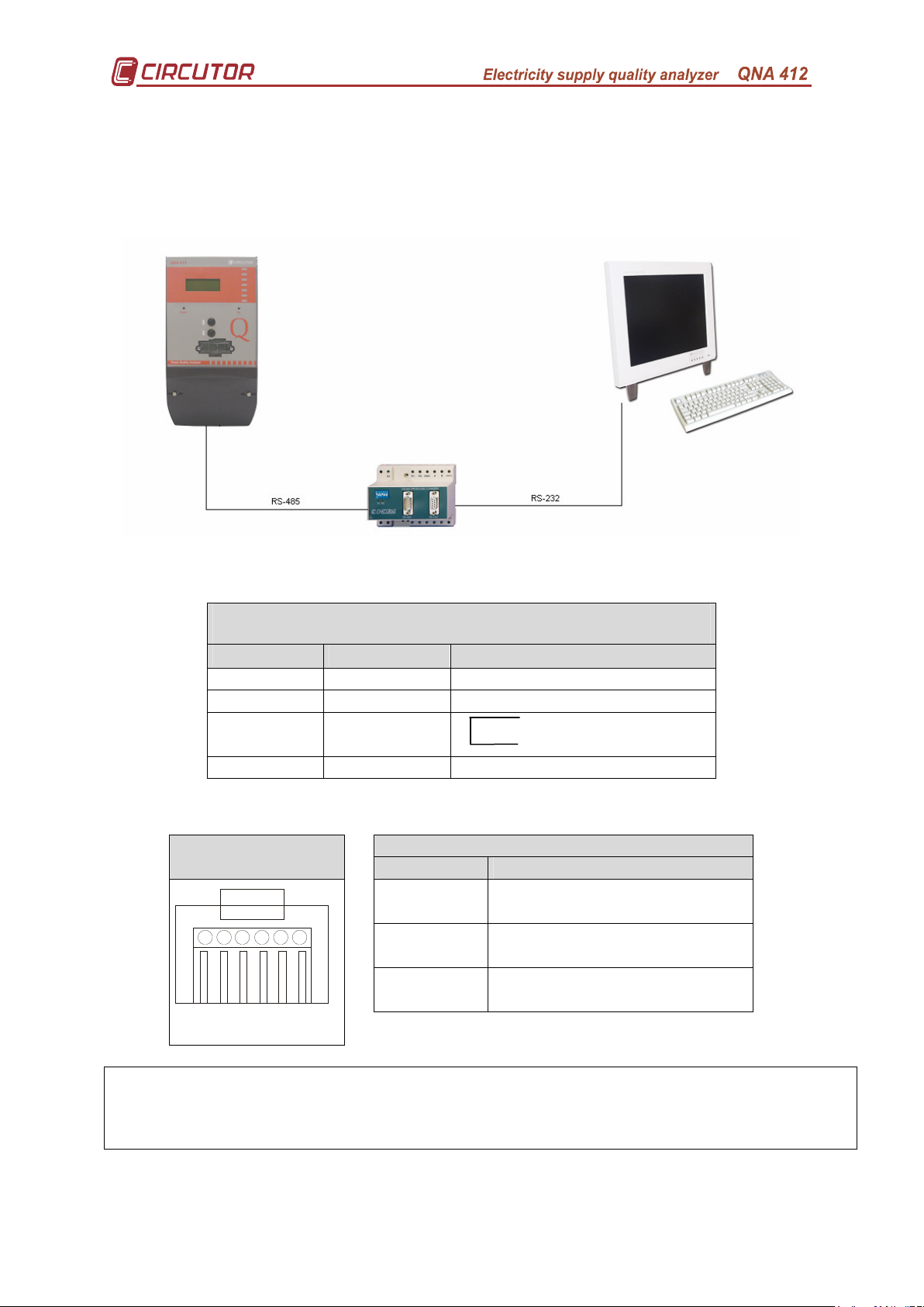
B. Appendix: Communications with QNA-412 (RS485).
The QNA-412 has the option for RS-485 communication with a PC. This
connection is via the R2 port on the QNA.
This type of communication is done when the equipment is at a considerable
distance (maximum 1200m) from the computer from which readings are to be made.
To connect in this way, the cables that must be used are:
• PC. RS-232 / RS-485 Converter
RS-232
P.C. (DB9) P.C. (DB25) RS-232/485 (DB9) Converter
3–Tx 2–Tx 2–Rx
2–Rx 3–Rx 3–TX
7–RTS
8–CTS
5–GND 5–GND 5–GND
• QNA-412 RS-232 / RS-485 Converter
QNA-412
QNA-412 RS-232/485 (DB9) Converter
2–Tx/Rx(-) 2–Tx/Rx (-)
RS-485
3–Tx/Rx(+) 1–Tx/Rx (+)
6–GND 5–GND
4
2
1 6
5
3
Ensure that the RS-232 cable is not connected to the PC. This is a priority port for
the RS-485.
This connection will prevent the QNA from communicating via the RS-485 port.
Page no. 31
Page 33
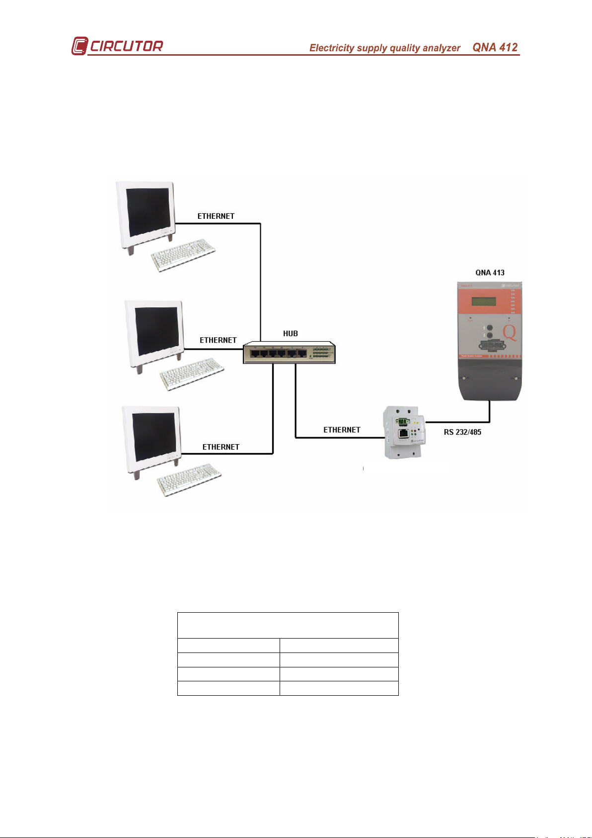
C. Appendix: Communications via TCP-IP converter.
The QNA may also be connected to a PC via an ETHERNET system.
In order to configure this, CIRCUTOR S.A. has a TCP-IP / RS 232-485
converter that allows any piece of equipment with RS-232 or RS-485 communication
to be connected to a PC via an ETHERNET system.
TCP/IP CONVERTER
To set the converter so that it converts the signal to RS-485, use the switch on
the converter itself. Check that the cable joining the QNA-412 with the TCP/IP
converter respects the Tx/Rx connection.
TCP/IP
QNA-412 TCP/IP Converter
3 A (+)
2 B (-)
6 S (GND)
Page no. 32
Page 34
D. Appendix : Installing and starting up the QNA-GSM.
Configure the QNA-412 before installing the new SIM card.
The contracted GSM line must be enabled for data transmission!!!
In order for the QNA to be able to communicate via the GSM Modem on the
QNA-412 GSM/RS-232 it is first necessary to configure the SIM card for the
telephone line that is to be used.
To do this it is always necessary to install a new SIM card in the QNA GSM.
This is both for when it is being done for the first time and when changing the SIM
card.
To do so it will be necessary to:
1. Without introducing the SIM card:
1) Start the QNA.
2) Connect the QNA via the RS-232 series port using a communications
cable.
3) Using the PC software: Add a QNA or, when changing the SIM card,
change the setting for the existing QNA.
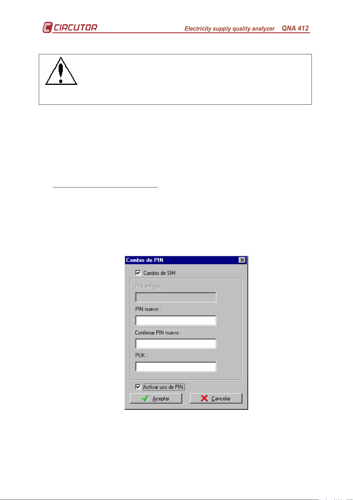
4) In the software option, general parameters, select option "Change PIN".
The following screen will appear:
5) Select the options “Change SIM” and “Activate PIN use”.
6) Enter the PIN and the PUK for the SIM card to be installed.
7) Accept the operation and follow the steps shown by the software:
a. Enter the new SIM card and then disconnect the RS-232
communications cable from the equipment.
Page no. 33
Page 35
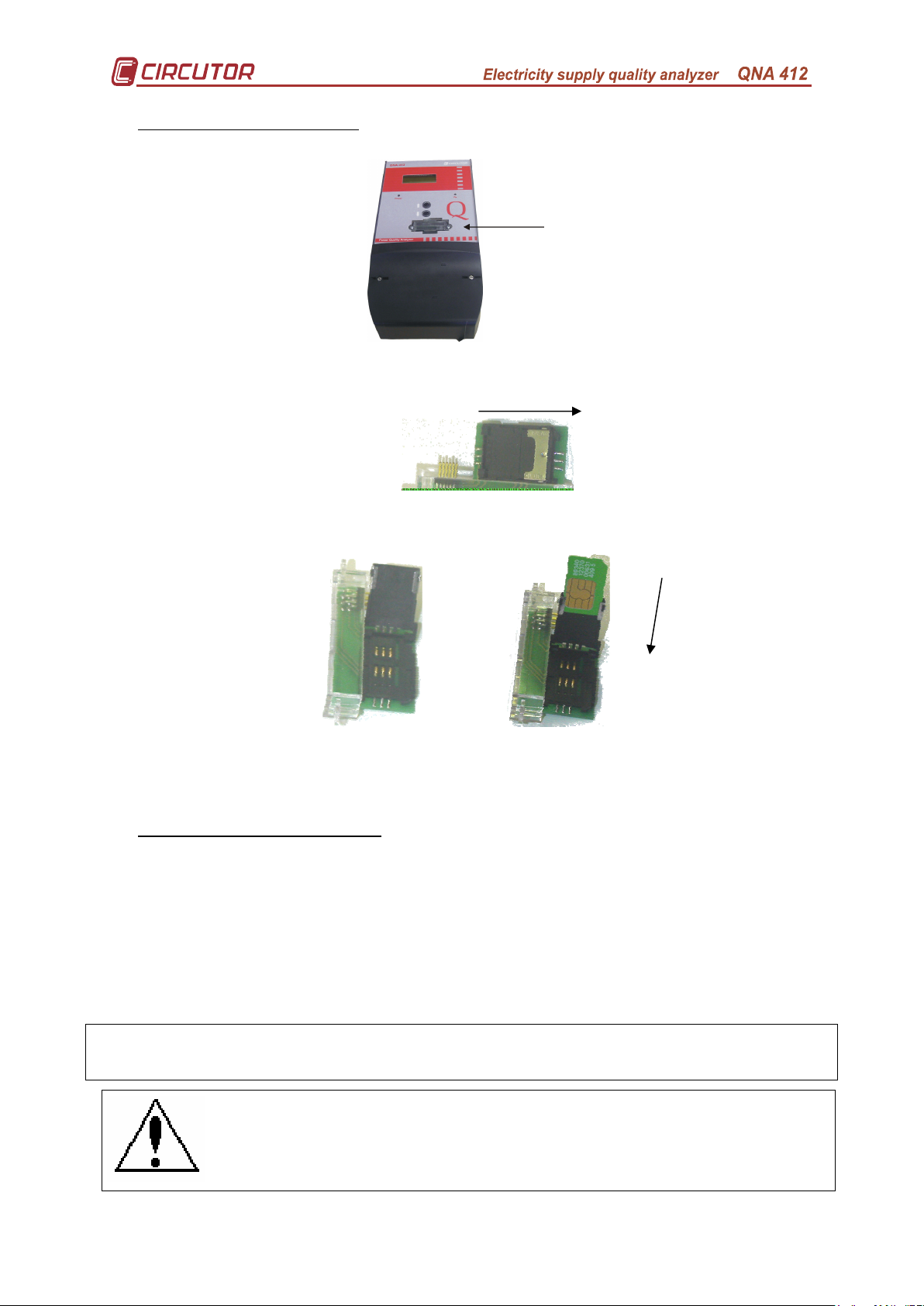
Ta pa
Soporte SIM
2. How to install the SIM card
8) Undo the screws from the SIM card holder cover.
SIM card
holder cover
9) Carefully remove the part.
10) Take out the SIM card safety holder.
11) This safety position will allow the holder to be opened and the SIM card installed.
12) Close the holder and replace it in its original position.
13) Gently attach the cover for the SIM card holder on the QNA.
14) Screw on the cover to avoid operating problems with the SIM card.
3. With the new SIM card installed:
15) Disconnect the RS-232 cable from the equipment.
16) Wait for indication from the PC software (Approximately 60 secs.).
17) Reconnect the RS-232 communications cable to the QNA.
18) Check that the PC software de PC is showing the result of the action. If the result
is:
Satisfactory: The QNA modem is ready to operate.
Error: It has not been possible to start the SIM card. Check the setting again.
Very carefully follow all the steps.
After installation, check that the RS-232 cable is not connected to the PC.
If it is connected, it will prevent the QNA from communicating via the GSM modem.
The local modem must not be connected via a telephone
switchboard. It must be a direct line.
Page no. 34
Page 36

Input
: V1-V2
V2-V3
V3-V1
EVERY 24 HOURS
Vrms
DIP,
OVERVOLTAGE,
UNBALANCE
CALCULATION
UNBALANCE
150 CYCLES
UNBALANCE
CALCULATION
OVER 10 MINUTES
HARMONICS
AND THD/d
CALCULATION
CnSH HARMONICS
MAX CnSH VALUE
PST
CALCULATION
AND STORAGE
IN STD FILE
FLICKER
MEASUREMENT
MAX CnVS VALUE
E. Appendix: The QNA's measurement method.
EVERY 6
SAMPLES
EVERY HALF
CYCLE
Pinst
EVERY CYCLE
EVERY 10 CYCLES
Vrms
CALCULATION
150 CYCLES
CALCULATION
FOR 10 MIN.
AND STORAGE
IN STD FILE
INTERRUPTION,
UNBALANCE,
EVQ STORAGE
CALCULATION
CALCULATION
AND STORAGE
IN STD FILE
CALCULATION
FOR HARMONICS
STATISTICS
H24 FILE
AND STORAGE
IN STD FILE
CALCULATION
FOR HARMONICS
STATISTICS
H24 FILE
Page no. 35
 Loading...