

Page 1
POWER QUALITY ANALYZER
QNA500 8IO
INSTRUCTION M ANUAL
(M98239501-03-13A)
Page 2
POWER QUALITY ANALYZER QNA500 8IO
Una conexión incorrecta del equipo puede producir la muerte, lesiones graves y riesgo de incendio. Lea y
ATENCIÓN
Death, serious injury, or fire hazard could result from improper connection of this instrument. Read and
WARNING
Un branchement incorrect de l’appareil peut entraîner la mort ou des lésions graves et peut provoquer un
ATTENTION
ADVERTENCIAS / SÍMBOLOS
PELIGRO
DANGER
entienda el manual antes de conectar el equipo. Observe todas las instrucciones de instalación y operación
durante el uso de este instrumento.
La instalación, operación y mantenimiento de este instrumento debe ser efectuado por personal cualificado
solamente. El Código Eléctrico Nacional define a una persona cualificada como una que esté familiarizada
con la construcción y operación del equipo y con los riesgos involucrados.
Consultar el manual de instrucciones antes de utilizar el equipo
En el presente manual, si las instrucciones precedidas por este símbolo no se respetan o realizan
correctamente, pueden ocasionar daños personales o dañar el equipo y /o las instalaciones.
WARNINGS / SYMBOLS
understand this manual before connecting this instrument. Follow all installation and operating instructions
while using this instrument.
Installation, operation, and maintenance of this instrument must be performed by qualified personnel only.
The National Electrical Code defines a qualified person as one who has the skills and knowledge related to
the construction and operation of the electrical equipment and installations, and who has received safety
training on the hazards involved.
DANGER
Read the instructions manual before using the equipment.
In this manual, if the instructions preceded by this symbol are not met or done correctly, can cause personal
injury or equipment damage and / or facilities.
ADVERTISEMENTS / SYMBOLE
incendie. Avant de brancher votre appareil, lisez attentivement le manuel et assurez-vous de bien avoir
compris toutes les explications données. Respectez toutes les instructions concernant le mode
d’installation de l’appareil et son fonctionnement.
L’installation, le fonctionnement et la maintenance de cet appareil doivent être réalisés uniquement par
du personnel qualifié. Le code électrique national définit en tant que personne qualifiée toute personne
connaissant le montage et le fonctionnement de l’appareil ainsi que les risques que ceux-ci comportent.
Consulter le manuel d’instructions avant d’utiliser l’appareil
Si les instructions suivantes, précédées dans le manuel d’un symbole, ne sont pas respectées ou sont
réalisées incorrectement, elles pourront provoquer des dommages personnels ou abîmer l’appareil et/ou
les installations.
QNA500 8IO Instruction manual
2 / 111
Page 3
POWER QUALITY ANALYZER QNA500 8IO
Durch einen nicht sachgemäßen Anschluss der Anlage können Tod, schwere Verletzungen und
ACHTUNG
Uma ligação incorrecta do equipamento pode provocar a morte, lesões graves e risco de incêndio. Leia e
compreenda o manual antes de ligar o equipamento. Observe todas as instruções de instalação e
vadas a cabo exclusivamente por
ATENÇÃO
No presente manual, se as instruções que precedem este símbolo não forem respeitadas ou realizadas
Un collegamento errato del dispositivo può provocare morte, lesioni gravi nonché rischio di incendio.
Prima di collegare il dispositivo leggere attentamente il manuale. Osservare tutte le istruzioni relative
L’installazione, operatività e manutenzione di questo strumento devono essere realizzate solamente da
ATTENZIONE
Qualora le istruzioni riportate nel presente manuale precedute da questo simbolo non vengano osservate
realizzate correttamente, possono provocare danni personali o danneggiare il dispositivo e/o gli
WARNHINWEISE / SYMBOLE
GEFAHR
PERIGO
Brandrisiko hervorgerufen werden. Bevor Sie die Anlage anschließen, lesen Sie bitte das Handbuch
durch und machen Sie sich dessen Inhalt klar. Beachten Sie bei Einsatz dieses Instrumentes sämtliche
Installations- und Betriebshinweise.
Installation, Betrieb und Wartung dieses Instrumentes müssen ausschließlich von entsprechend
qualifiziertem Personal vorgenommen werden. Von dem nationalen Elektrocode wird eine qualifizierte
Person als jemand definiert, der mit der Konstruktion und dem Betrieb einer Anlage und der damit
verbundenen Risiken vertraut ist.
Vor Inbetriebnahme der Anlage ist das Handbuch zu lesen.
Werden die in dem vorliegenden Handbuch mit diesem Symbol versehenen Hinweise nicht beachtet oder
falsch verstanden, können Personenschäden und Schäden an der Anlage und/oder den Installationen
verursacht werden.
ADVERTÊNCIAS / SÍMBOLOS
operação durante o uso deste aparelho.
A instalação, operação e manutenção deste aparelho devem ser le
pessoal qualificado. O Código Eléctrico Nacional define uma pessoa qualificada como uma pessoa que
se encontre familiarizada com a construção e operação do equipamento assim como com os riscos
inerentes.
Consultar o manual de instruções antes de utilizar o equipamento
de forma correcta, podem ocorrer ferimentos pessoais ou danos no equipamento e/ou nas instalações.
AVVERTENZE / SIMBOLI
PERICOLO
all’installazione e all’operatività durante l’uso di questo strumento.
personale qualificato. Il Codice Elettrico Nazionale definisce una persona qualificata come colui che ha
familiarità con la costruzione e operativ ità del dis po sitiv o e co n i rischi che ne possano der ivar e.
Consultare il manuale di istruzioni prima di utilizzare il dispositivo
o
QNA500 8IO Instruction manual
impianti.
3 / 111
Page 4

POWER QUALITY ANALYZER QNA500 8IO
CONTENTS
1.- DISCLAIMER ................................................................................................................................ 7
2.- SAFETY PRECAUTIONS.............................................................................................................. 7
3.- INTRODUCTION ........................................................................................................................... 7
3.1.- GENERAL DESCRIPTION .................................................................................................... 7
3.2.- MULTIFIT SYSTEM MODULES ............................................................................................ 8
3.3.- REGISTRY VARIABLES ....................................................................................................... 9
4.- INTERCONNECTING MODULES ............................................................................................... 10
5.- INSTALLATION ........................................................................................................................... 10
5.1.- VERIFICATION UPON RECEPTION .................................................................................. 10
5.2.- ASSEMBLY ......................................................................................................................... 11
5.3.- INSTALLATION METHODS ................................................................................................ 12
5.3.1.- PROCEDURE ............................................................................................................ 12
5.4.- CONNECTING THE ANALYZER ........................................................................................ 13
5.4.1.- AUXILIARY POWER SUPPLY ................................................................................... 13
5.4.2.- NOMINAL VOLTAGE OF THE VOLTAGE MEASUREMENT CIRCUIT ..................... 13
5.4.3.- NOMINAL CURRENT OF THE CURRENT MEASUREMENT CIRCUIT .................... 13
5.4.4.- OPERATING CONDITIONS ...................................................................................... 13
5.4.5.- SAFETY ..................................................................................................................... 13
5.5.- DESCRIPTION OF THE TERMINALS ................................................................................ 14
5.5.1.- CONNECTING THE POWER SUPPLY MODULE ..................................................... 14
5.5.2.- VOLTAGE AND CURRENT CONNECTIONS ............................................................ 15
5.5.3.- CONNECTING INPUTS-OUTPUTS ........................................................................... 16
5.6.- COMMUNICATION CONNECTION DIAGRAM ................................................................... 17
5.6.1.- RS-232 ...................................................................................................................... 17
5.6.2.- RS-485 ...................................................................................................................... 18
5.6.3.- ETHERNET ............................................................................................................... 18
5.7.- MEASUREMENT CONNECTION DIAGRAMS .................................................................... 20
5.7.1.- 4 CURRENT TRANSFORMERS AND 5 VO LT AGE REFERENCES.......................... 20
5.7.2.- 3 CURRENT TRANSFORMERS AND 2 VOLTAGE TRANSFORMERS .................... 20
5.8.- CONNECTING POWER SUPPLY ....................................................................................... 21
6.- OPERATION OF THE QNA500 (MULTIFIT SYSTEM DESCRIPTION) ....................................... 22
QNA500 8IO Instruction manual
4 / 111
Page 5

POWER QUALITY ANALYZER QNA500 8IO
6.1.- PHYSICAL DESCRIPTION .................................................................................................. 22
6.1.1.- BASE MODULE (M-BASE) ......................................................................................... 22
6.1.2.- MEASUREMENT MODULE (QNA500) ....................................................................... 23
6.1.3.- INPUT-OUTPUT CENTRALIZER MODULE (M-8IO) .................................................. 24
6.2.- SUPPLY THE POWER QUALITY ANALYZER..................................................................... 25
7.- BASE MODULE SETUP (M-BASE) ............................................................................................. 26
7.1.- COMMUNICATIONS............................................................................................................ 26
7.1.1.- IP ADDRESS CONFIGURATION ............................................................................... 27
7.1.1.- IGMP CONFIGUARTION ............................................................................................ 28
7.1.2.- NTP SYNCHRONIZATION ......................................................................................... 29
7.1.3.- DEVICE NUMBER CONFIGURATION ....................................................................... 29
8.- POWER QUALITY ANALYZER SETUP (M-QNA500) .................................................................. 30
8.1.- COMMUNICATIONS............................................................................................................ 30
8.2.- MEASUREMENT ................................................................................................................. 30
8.3.- POWER QUALITY ............................................................................................................... 32
8.4.- TRANSIENTS ...................................................................................................................... 32
8.5.- REMOVE FILES .................................................................................................................. 33
8.6.- CLOCK ................................................................................................................................ 34
8.7.- BATTERY ............................................................................................................................ 34
8.8.- STANDARD RECORDING PERIOD .................................................................................... 34
8.9.- ENERGY RECORDING PERIOD ........................................................................................ 34
8.10.- SELECTING VARIABLES TO BE RECORDED ................................................................. 34
8.11.- ALARM SETUP (DIGITAL OBJECTS) ............................................................................... 35
8.12.- FACTORY PRESETS ........................................................................................................ 37
8.13.- RECORDING FILES .......................................................................................................... 38
8.13.1.- .STD FILE ................................................................................................................. 38
8.13.2.- .WAT FILE ................................................................................................................ 41
8.13.3.- .EVQ FILE ................................................................................................................ 41
8.13.4.- .EVA FILE ................................................................................................................. 42
8.13.5.- .CFG AND .DAT FILES............................................................................................. 42
9.- INPUT/OUTPUT MODULE SETUP (M-8IO) ................................................................................ 43
9.1.- COMMUNICATIONS............................................................................................................ 43
9.2.- DIGITAL INPUTS ................................................................................................................. 44
QNA500 8IO Instruction manual
5 / 111
Page 6

POWER QUALITY ANALYZER QNA500 8IO
9.3.- DIGITAL OUTPUTS ............................................................................................................ 44
9.4.- FILES .................................................................................................................................. 45
9.4.1.- .STD FILE .................................................................................................................. 45
9.4.2.- .EVA FILE .................................................................................................................. 45
9.5.- ALARM SETUP (DIGITAL OBJECTS) ................................................................................ 46
10.- WEB SERVER ...................................................................................................................... 47
10.1.- INTRODUCTION ............................................................................................................... 47
10.2.- M-BASE SETUP ............................................................................................................... 47
10.3.- QNA500 SETUP ............................................................................................................... 54
10.4.- M-8IO SETUP ................................................................................................................... 70
11.- COMMUNICATIONS PROTOCOLS ..................................................................................... 84
11.1.- MODBUS / RTU ................................................................................................................ 84
11.1.1.- MODBUS/RTU MEMORY ADDRESS LIST OF THE QNA500 ................................. 85
11.1.2.- MODBUS/RTU MEMORY ADDRESS LIST OF THE M-8IO MODULE ..................... 99
11.2.- MODBUS/TCP ................................................................................................................ 100
11.3.- ZMODEM ........................................................................................................................ 100
11.4.- CIRBUS .......................................................................................................................... 101
11.4.1.- CIRBUS INSTRUCTIONS LIST ............................................................................. 101
11.5.- FTP ................................................................................................................................. 105
12.- MAINTENANCE .................................................................................................................. 106
13.- TECHNICAL FEATURES .................................................................................................... 107
14.- SAFETY .............................................................................................................................. 109
15.- DIMENSIONS ..................................................................................................................... 109
16.- TECHNICAL SERVICE ....................................................................................................... 109
17.- APPENDIX 1 – COMMUNICATIONS RS-485 WITH CVM POWER ANALYZERS .............. 110
18.- APPENDIX II – WIRING DIAGRAM TO CONNECT ENERGY METERS WITH
PULSE OUTPUT WITH M-8IO ........................................................................................................... 111
QNA500 8IO Instruction manual
6 / 111
Page 7
POWER QUALITY ANALYZER QNA500 8IO
1.- DISCLAIMER
CIRCUTOR, SA reser ves the right to make modifications to the device or the equipment specifications
set out in this instruction manual without prior notice. CIRCUTOR, SA ad vises the user to obtain the
latest version of the specifications and applications of the device at http://www.circutor.com
CIRCUTOR, SA recommends the use of the original cables and accessories supplied
with the equipment.
2.- SAFETY PRECAUTIONS
Follow the warnings described in this manual with the symbols shown below.
DANGER
Warns about an electrical risk.
ATTENTION
Indicates message or warning requiring special attention.
3.- INTRODUCTION
3.1.- General description
This manual provides the information required to install, configure and handle the QNA500 8IO (to
simplify QNA500) power quality analyzer and to achieve the optimum performance. Read it carefully
and observe the safety instructions and regulations at all times.
QNA500 8IO is a power quality analyzer that measures, calculates and records the main electrical
parameters of three-phase balanced or RMS industrial networks, as well as the power quality
parameters in the same electrical network.
The measurements are taken in true root mean squared (TRMS), with five alternating voltage inputs
(3P+N+PE) and five current inputs (3P+N+I
to external current transformers. The power quality analyzer QNA500 is a programmable measuring
instrument. It offers a series of operating options that can be selected from the menus on its WEB
server or the software supplied by CIRCUTOR. Read carefully the following sections before start-up
the product: power supply, connection and configuration. In addition, select the most suitable operating
mode to collect the required data.
leak) to measure the secondaries of /1A or /5A, connected
QNA500 8IO Instruction manual
7 / 111
Page 8

POWER QUALITY ANALYZER QNA500 8IO
CODE
DESCRIPTION
M-QNA500
Power quality analyzer
M-8IO
Centralizer with 8 digital inputs / 8 digital outputs (optomosfet):
M-8IOR
Centralizer with 8 digital inputs / 8 digital outputs (relay):
QM-500 DISPLAY
On-line display to monitor variables of the QNA500 module
The advanced power handling features of the QNA500 analyzer can measure and record over 500
electrical parameters, in order to analyze and control the electrical network.
The main features of the analyzer are as follows:
• 5 voltage measurement inputs (3P+N+PE)
• 5 current measurement inputs (3P+In+Id (
Earth-leakage current))
• Class 0.2 energy and power ac cur ac y
• 512 samples/cycle
• Configurable capture of transients and other disturbances in the installation
• Configurable register of over 500 electrical variables
• Maximum and minimum value registers
• DIN rail or rear PANEL fixing.
• WEB Serve r
• 3 communications ports (RS-232, RS-485 and ETHERNET)
• Communications protocols: MODBUS/RTU, MODBUS/TCP, COMTRADE, HTTP, FTP and
ZMODEM
• Additional input and output modules to expand the performance of the analyzer
• Internal battery to guarantee the operation of the power quality analyzer in the absence of
power supply
3.2.- MULTIFIT System modules
The MULTIFIT system has various expansion modules that can expand its performance features.
The modules available are the followings:
• Base power supply and communications station (M-BASE)
• Power quality analyzer (M-QNA500)
• Energy manager and alarms for 8inputs + 8outputs (M-8IO)
Additional modules can be added to the assembly to cater f or future expansion requirements. Also take
into account that each M-BASE module can power a maximum number of modules, in accordance with
the total consumption.
The following cards are available:
QNA500 8IO Instruction manual
8 / 111
Page 9
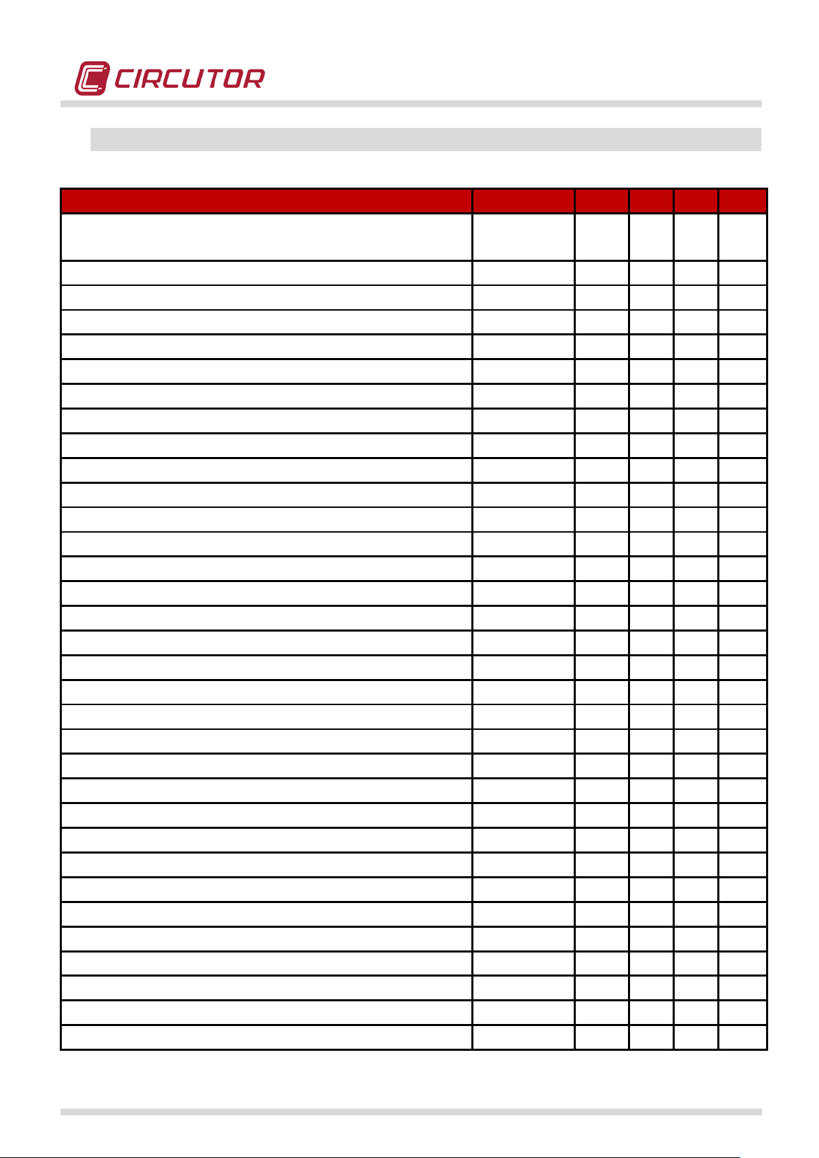
3.3.- REGISTRY VARIABLES
Register variables
Unit
L1
L2
L3
III
Phase-phase and phase-neutral voltage (average,
V
X X X
X
Current (average, maximum, minimum)
A
X X X X Neutral current (average, maximum, minimu m)
A
X Earth-Leakage current (average, maximum, minimum)
A
X Neutral-Ground voltage (average, maximum, minimum)
V
X Frequency (average, maximum, mini mu m)
Hz
X X X Active power (average, maximum, mini mum)
kW
X X X X Inductive reactive power (average, maximum, min imum)
kvar
X X X X Capacitive reactive power (average, maximum, min imum)
kvar
X X X X Apparent power (average, maximum, minimum )
KVAR
X X X X Maximum demand
kW
X X X Power factor (average, maximum, mini mum)
X X X X Crest factor (voltage and current)
V or A
X X X K Factor
X X X Active energy
kWh
X X X X Inductive reactive energy
kvarh
X X X X Capacitive active energy
kvarh
X X X X Voltage THD (average, maximum, minimum)
%
X X X Current THD (average, maximum, minimum))
%
X X X Voltage harmonics (up to 50th order)
V Harm
X X X Current harmonics (up to 50th order)
A Harm
X X X Voltage interharmonics (up to 50th order)
V Harm
X X X Current interharmonics (up to 50th order)
A Harm
X X X Flicker (PST)
X X X Overvoltage
%
X X X Sags
%
X X X Interruptions
%
X X X Voltage transients
X X X Current transients
X X X Voltage Unbalance (Vd/Vi)
X Voltage Asymmetry (Vh/Vi)
X Current Unbalance (Id/Ii)
X Current Asymmetry (Ih/Ii)
X
The power quality analyzer can measure:
maximum, minimum)
POWER QUALITY ANALYZER QNA500 8IO
QNA500 8IO Instruction manual
9 / 111
Page 10
POWER QUALITY ANALYZER QNA500 8IO
NOTE: do not connect more modules than those stated in the specifications. Otherwise,
4.- INTERCONNECTING MODULES
The MULTIFIT unit system can be used to interconnect various modules. Modules do not have to be
connected in a specific order. In any case, CIRCUTOR supplies two factory configurations:
1. M-BASE + M-QNA500
2. M-BASE + M-QNA500 + M-8IO
The MULTIFIT internal communications system allows each module to operate independently (Master
mode), so that each module can take its own decisions, regardless of the type of c onnection.
Modules are interconnected with a communications connector (26 PINS) located on the side of each
module. Once all modules have been installed, it is advisable to close the side connector of the last
module with the cover supplied with the equipment. The M-BASE can only power a specific number of
modules, due to the consumption of each one. The maximum capacity of each M-BASE module can be
used to power 2 QNA500 systems and 2 M-8IO or 4 M-8IO systems.
the equipment's operation could be severely affected.
5.- INSTALLATION
This manual contains information and warnings that the user must observe in order to guarantee the
safe operation of the equipment, so that it is in perfect working order and respects the safety
regulations.
If the equipment is used in a manner other than that specified by the manufacturer, its
protection elements may be compromised.
5.1.- VERIFICATION UPON RECEPTION
Check the following points when you receive the instrument:
• Make sure that the equipment is as specified on your order.
• Make sure that it has not been dam aged during transport.
• Make sure that there is a quick guide and/or adequate manuals with the equipment.
• Make sure that the following accessories have been supplied with the equipment:
o RS-232 Communications cable
o Ni-MH Battery
o DIN RAIL Fixing guides (1 guide + 1 fixing element per module)
o REAR PANEL fixing brackets
o Power supply and measurement connection terminal strip
QNA500 8IO Instruction manual
10 / 111
Page 11
POWER QUALITY ANALYZER QNA500 8IO
The safe use of the QNA500 power quality analyzer requires people who install or
it to follow the general safety measures, as well as the warnings documented in
This power quality analyzer should only be installed and maintained by qualified staff.
The product must be disconnected from the auxiliary power supply sources and from the
measurement in case its safety protection elements have been overridden (visible
damage has been detected). In this case, contact a qualified technical service
o Input and output terminal strips (when using a M-8IO module)
handle
the Instruction Manual.
5.2.- ASSEMBLY
ENVIRONMENTAL CONDITIONS
This equipment should be used at a temperature of -10ºC to +55ºC to guarantee its optimum operation,
with a relative humidity of 5 to 95%, with no condensation (temperature margin, as stated in the UL
certification). These technical features are guaranteed under internal laboratory tests at -10...55ºC.
CONSIDERATIONS
QNA500 8IO must be installed in a distribution cabinet that protects the analyzer from environmental
contaminating substances, such as oil, humidity, dust and corrosive vapours or other volatile
substances.
representative.
The analyzer has two basic installation methods:
• As a compact equipment in a distribution cabinet, installed on the rear PANEL
• As a modular equipment, installed on a DIN 46277 rail (EN 50022)
QNA500 8IO Instruction manual
11 / 111
Page 12
POWER QUALITY ANALYZER QNA500 8IO
Illustration 3
Illustration 4
Illustration 6
Illustration 5
Illustration 1
Illustration 2
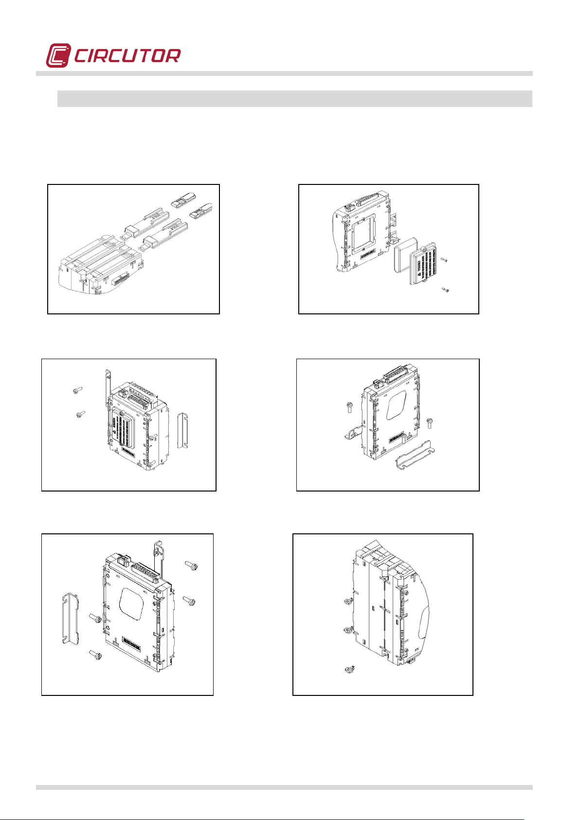
5.3.- INSTALLATION METHODS
The following figures show the different installation options established when the analyzer is
designed. The equipment's design allows an installation on a rear PANEL or DIN rail.
5.3.1.- PROCEDURE
Illustration 1: Shows how the DIN rail fixing elements should be attached to the rear of the analyzer. Once the guides are in place and the
analyzer has been attached to the DIN rail, remember to raise the guides to make sure they are correctly fastened.
Illustration 2: Shows how the analyzer's battery must be installed on the side of the M-BASE module.
Illustration 3: Shows one of the options for mounting the PANEL base attachment guides. The modules are somewhat symmetrical, and can
therefore be attached to the panel in various ways.
Illustration 4: Shows one of the options for mounting the PANEL base attachment guides.
Illustration 5: Shows how to insert the screws for fastening the analyzer to the PANEL base attachment elements.
Illustration 6: Shows how to insert the plastic clamps to fasten the modules. This point is very important, since the purpose of the clamps is to
guarantee that the modules are firmly secured.
QNA500 8IO Instruction manual
12 / 111
Page 13

POWER QUALITY ANALYZER QNA500 8IO
Disconnect the QNA500 from the power supply and measurement sources
before working on it to expand it with expansion modules, to modify the
is dangerous to handle the
equipment while it is under power.
5.4.- CONNECTING THE ANALYZER
Check the following sections before connecting the equipment:
1. Auxiliary voltage features
2. Maximum voltage of the voltage measurement circuit
3. Maximum current of the current measurement circuit
4. Operating conditions
5. Safety
5.4.1.- AUXILIARY POWER SUPPLY
Standard power supply: 90-300VAC / 100-300VCC
Frequency: 50…60 Hz
5.4.2.- NOMINAL VOLTAGE OF THE VOLTAGE MEASUREMENT CIRCUIT
Measurement voltage: 0…500 V (phase-neutral)
Maximum measurement voltage: 500/866 V (phase-neutral / phase-phase)
Frequency: 42.5…69 Hz
5.4.3.- NOMINAL CURRENT OF THE CURRENT MEASUREMENT CIRCUIT
Secondary current: /5 A
(standard model)
Secondary current: /1 A (depending on the model)
Maximum Current: 1.2 x I
secondary
5.4.4.- OPERATING CONDITIONS
Operating temperature: -10ºC to +55ºC
Relative humidity: 5…95%
Altitude: 2000 m
5.4.5.- SAFETY
The QNA500 has been specially designed for CAT IV 600V (CAT III 1000V) installations, in
compliance with the EN61010 standard. Designed and identified with the EC mark.
connections or to replace the equipment. It
QNA500 8IO Instruction manual
13 / 111
Page 14
5.5.- DESCRIPTION OF THE TERMINALS
The equipment must be connected to a power circuit protected with gl-type
breaker switch or equivalent
. (AWG 17). The current
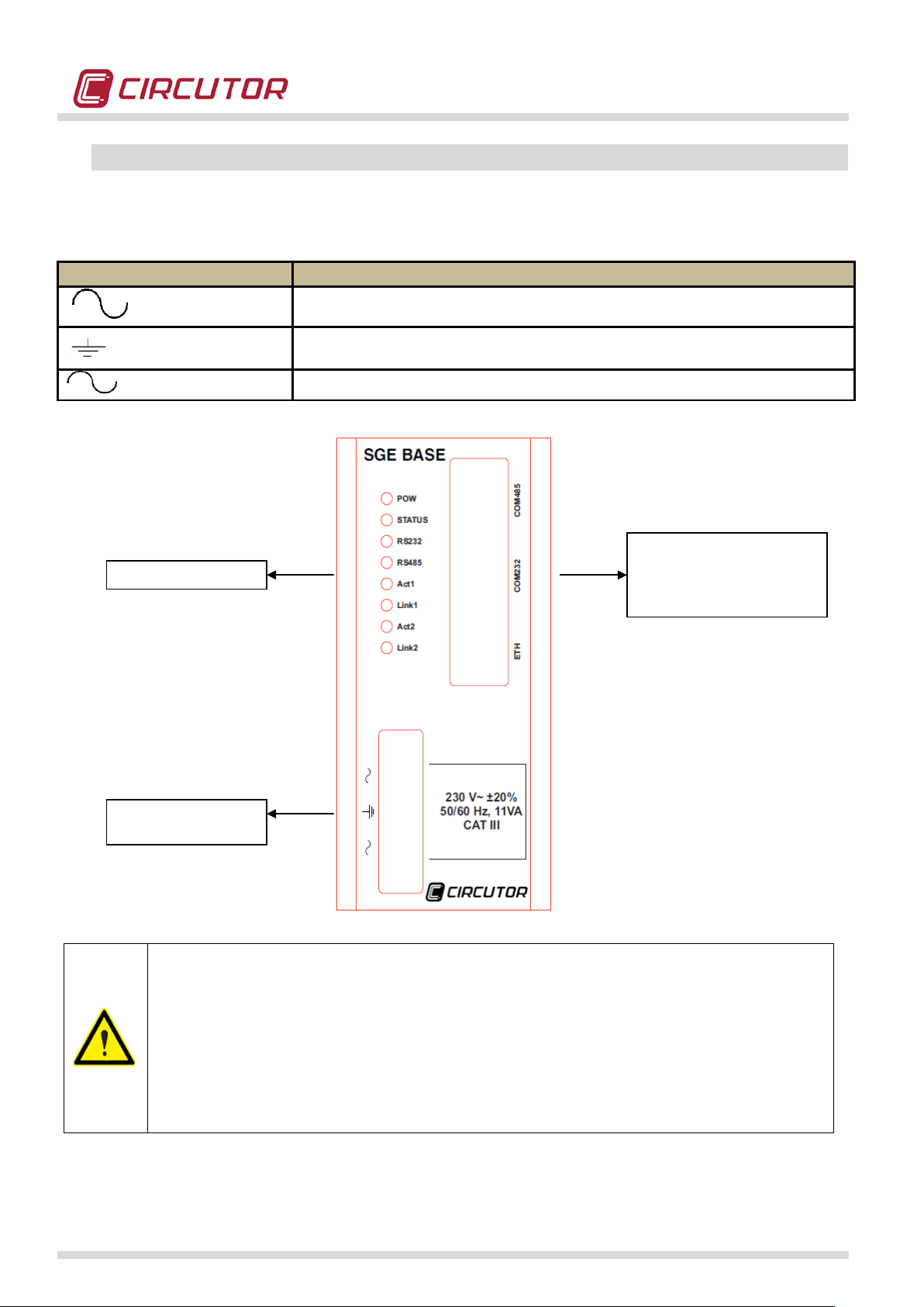
TERMINAL
DESCRIPTION
Power supply connection
Ground connection
Power supply connection
Indicator LED
Communications ports
ETHERNET
Auxiliary power
supply
5.5.1.- CONNECTING THE POWER SUPPLY MODULE
POWER QUALITY ANALYZER QNA500 8IO
RS-485
RS-232
fuses, in compliance with I EC 269, or M-type, with values from 0.5 to 1 A / 600
V (UL listed). It must be fitted with a circuitdevice, in order to be able to disconnect the device from the power supply.
The power circuit and voltage measurement circuits are connected with a
cable with a minimum cross-section of 1 mm
2
transformer's secondar y connection line must have a minimum cross-section
2
of 2 mm
. (AWG 14 Cu) and withstand a minimu m of 60ºC.
QNA500 8IO Instruction manual
14 / 111
Page 15
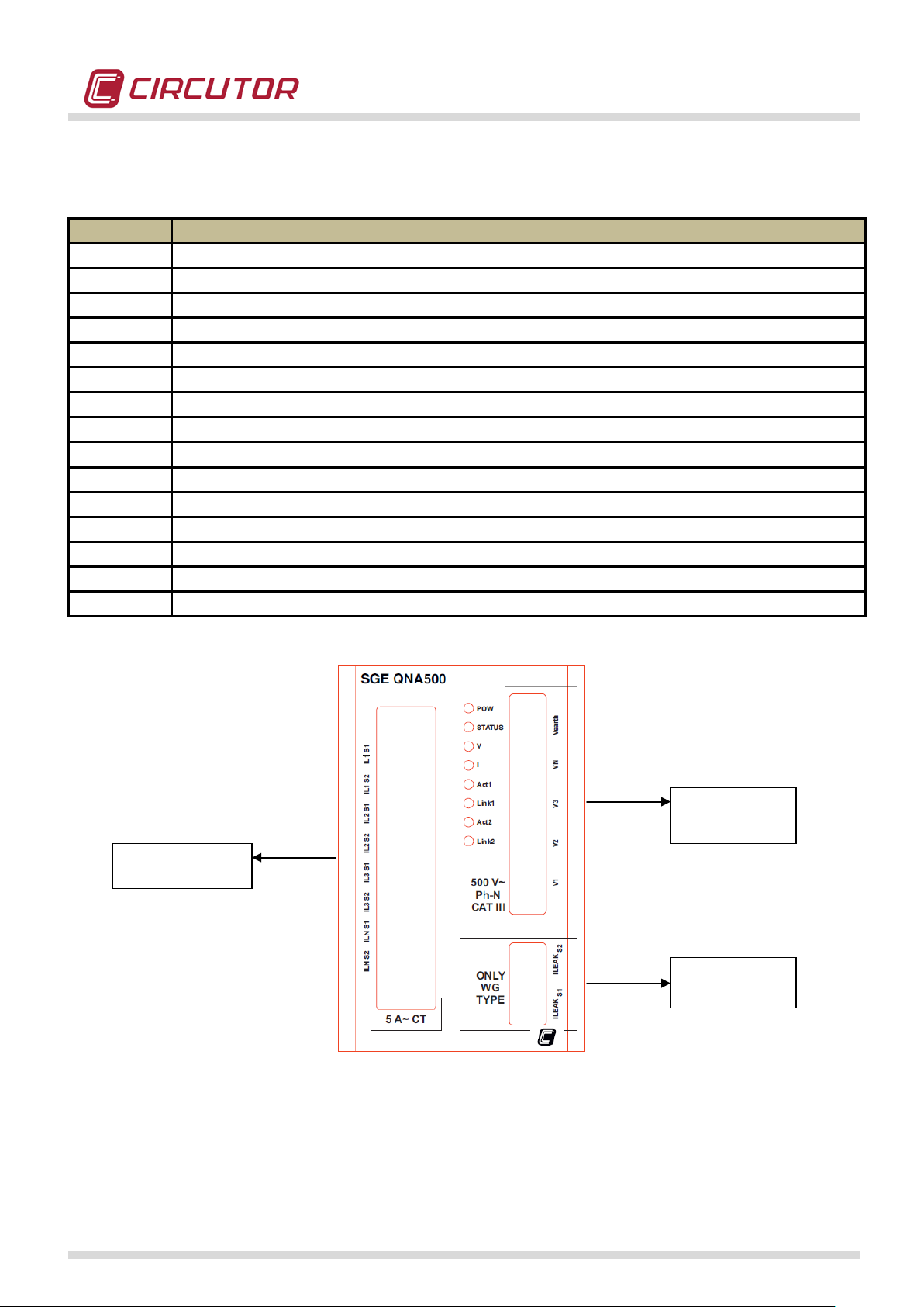
5.5.2.- VOLTAGE AND CURRENT CONNECTIONS
TERMINAL
DESCRIPTION
IL1 S1
S1 connection of CT Phase 1
IL1 S2
S2 connection of CT Phase 1
IL2 S1
S1 connection of CT Phase 2
IL2 S2
S2 connection of CT Phase 2
IL3 S1
S1 connection of CT Phase 3
IL3 S2
S2 connection of CT Phase 3
ILN S1
S1 connection of CT Neutral
ILN S2
S2 connection of CT Neutral
ILEAK S1
S1 connection of the earth leakage current transformer (I leak)
ILEAK S2
S2 connection of the earth leakage current transformer (I leak)
V1
Phase 1 voltage input
V2
Phase 2 voltage input
V3
Phase 3 voltage input
VN
Neutral voltage input
Vground
V Ground voltage input (PE)
Voltage
I leak
Current
measurement
POWER QUALITY ANALYZER QNA500 8IO
measurement
Measurement
QNA500 8IO Instruction manual
15 / 111
Page 16
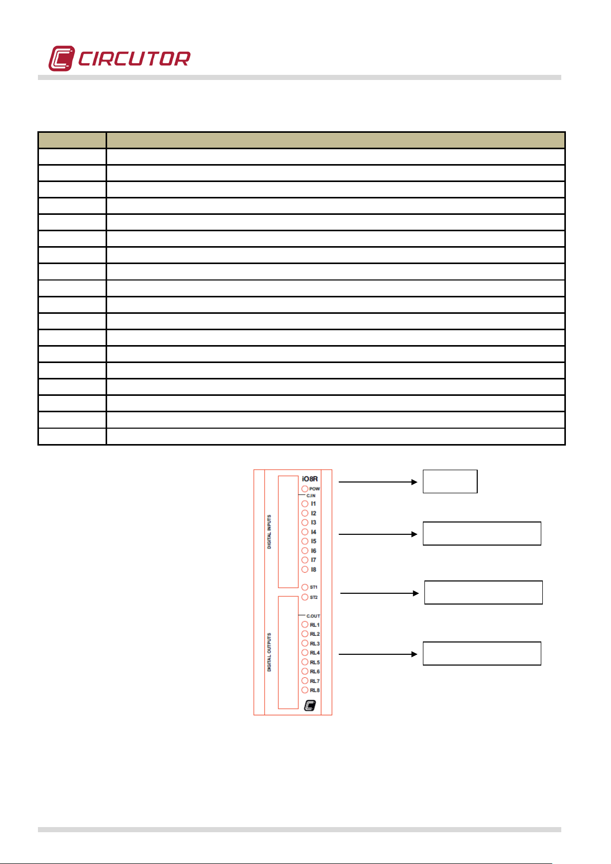
5.5.3.- CONNECTING INPUTS-OUTPUTS
TERMINAL
DESCRIPTION
CIN
Common input
I1
Digital input 1
I2
Digital input 2
I3
Digital input 3
I4
Digital input 4
I5
Digital input 5
I6
Digital input 6
I7
Digital input 7
I8
Digital input 8
C.OUT
Common output
O1 or RL1
Digital output 01 (transistor or relay, depending on the model)
O2 or RL2
Digital output 02 (transistor or relay, depending on the model)
O3 or RL3
Digital output 03 (transistor or relay, depending on the model)
O4 or RL4
Digital output 04 (transistor or relay, depending on the model)
O5 or RL5
Digital output 05 (transistor or relay, depending on the model)
O6 or RL6
Digital output 06 (transistor or relay, depending on the model)
O7 or RL7
Digital output 07 (transistor or relay, depending on the model)
O8 or RL8
Digital output 08 (transistor or relay, depending on the model)
Power
Digital inputs
Digital outputs
Status
POWER QUALITY ANALYZER QNA500 8IO
QNA500 8IO Instruction manual
16 / 111
Page 17
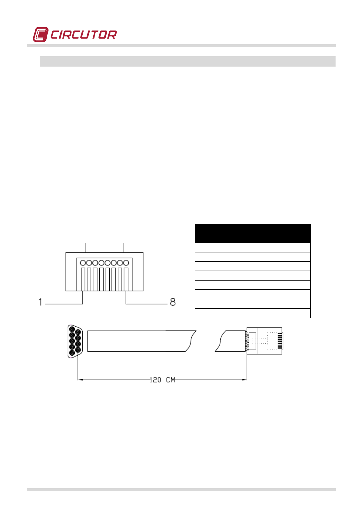
POWER QUALITY ANALYZER QNA500 8IO
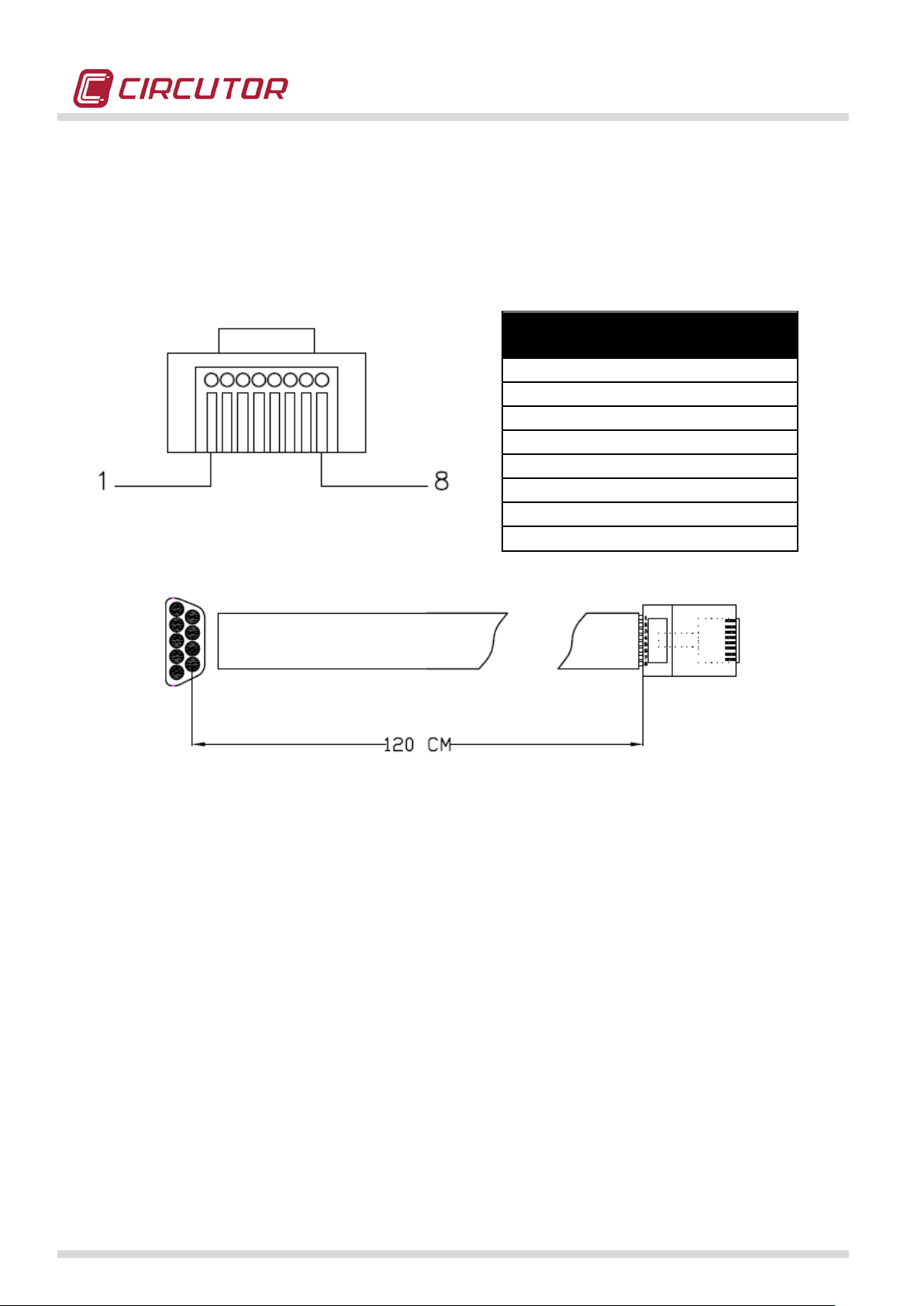
FRONT VIEW
(RJ45)
1 (Tx)
2 (Rx)
2 (Rx)
3 (Tx)
3 (CTS)
8 (DSR)
4 (GND)
5 (GND)
5 (GND)
5 (GND)
6 - 7 - 8
-
5.6.- COMMUNICATION CONNECTION DI AGRAM
M-BASE has 3 built-in communications ports that can send the information from the connected
modules to external devices. The ports are as follows:
• RS-232
• RS-485
• ETHERNET (TCP/IP)
The 3 communications ports operate as independent systems. In other words, they can simultaneously
request information from all connected modules.
5.6.1.- RS-232
QNA 500 system is supplied with an RS-232 communications cable. The cable wiring diagram is as
follows:
The RS-232 communications port can be used to access the different modules connected to the M-
BASE m odule. Each module has a peripheral number (default: M-BASE = 01, M-QNA500= 02 and M-
8IO = 10, M-8IOR=10), wh ich m ust be taken into account when establishing communications.
DB-9 CONNECTOR
QNA500 8IO Instruction manual
17 / 111
Page 18
POWER QUALITY ANALYZER QNA500 8IO
FRONT VIEW
(RJ45)
1 (Tx)
2 (Rx)
2 (Rx)
3 (Tx)
3 (CTS)
-
4 (GND)
-
5 (GND)
- 6 - 7 - 8 -
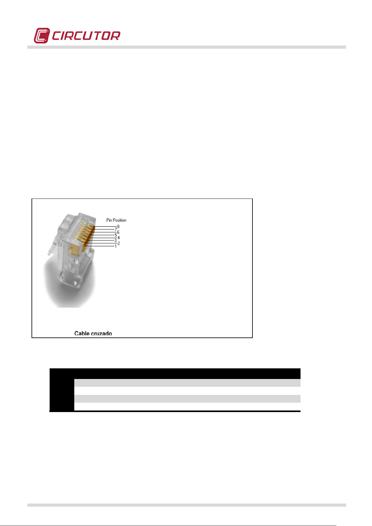
5.6.2.- RS-485
The QNA500 has a RS-485 communication port. This port can be used to communicate with several
devices. This type of bus uses two signals (Rx,Tx) to send and receive dat a. QNA500 is not supplied
with a RS-485 cable, since the cable lengths can change in each installation. The following diagram
must be taken into account to connect the RS-485 cable:
DB-9 CONNECTOR
The RS-485 LED of the M-BASE module will start flashing when communications are established
through this port.
RECOMMENDED CABLE:
Flexible cable, category 5, with 2 conductors x 0.25 mm
2
( AWG23) with a non-rigid cable, plus shield.
The shield must be grounded on one end t o discharge the noise induced on the cable. This cable can
also have a 0.22 mm
with a 0.25 mm
2
2
conductor cross-section (AWG24), although we recommend the use of cable
(or higher) cross-section.
5.6.3.- ETHERNET
The QNA500 has an ETHERNET communications port. The Ethernet communications are used to
connect the equipment in a LAN or WAN networks through various protocols, such as MODBUS/TCP,
CIRBUS/TCP, Z MODEM, HTTP or FTP. All use TCP/IP connections. Various ports are used for each
protocol through the IP configured for the port. These ports are as follows:
QNA500 8IO Instruction manual
18 / 111
Page 19
POWER QUALITY ANALYZER QNA500 8IO
Led
Power on
Flashing
Act1
No external activity
External TX/RX ETH activity established
Link1
ETH No external link
Act2
No activity with the modules
TX/RX ETH activity with the modules
Link2
ETH No link with the modules
10002: CIRBUS
14001: ZMODEM (telnet)
14002: ZMODEM (RAW)
20003: MODBUS/RTU
30003: MODBUS/TCP
80: HTTP
21: FTP
A standard UTP CAT 5 cable will be used.
M-BASE module has various activity LEDs for the Ethernet port, as in the case of a PC.
QNA500 8IO Instruction manual
19 / 111
Page 20
POWER QUALITY ANALYZER QNA500 8IO
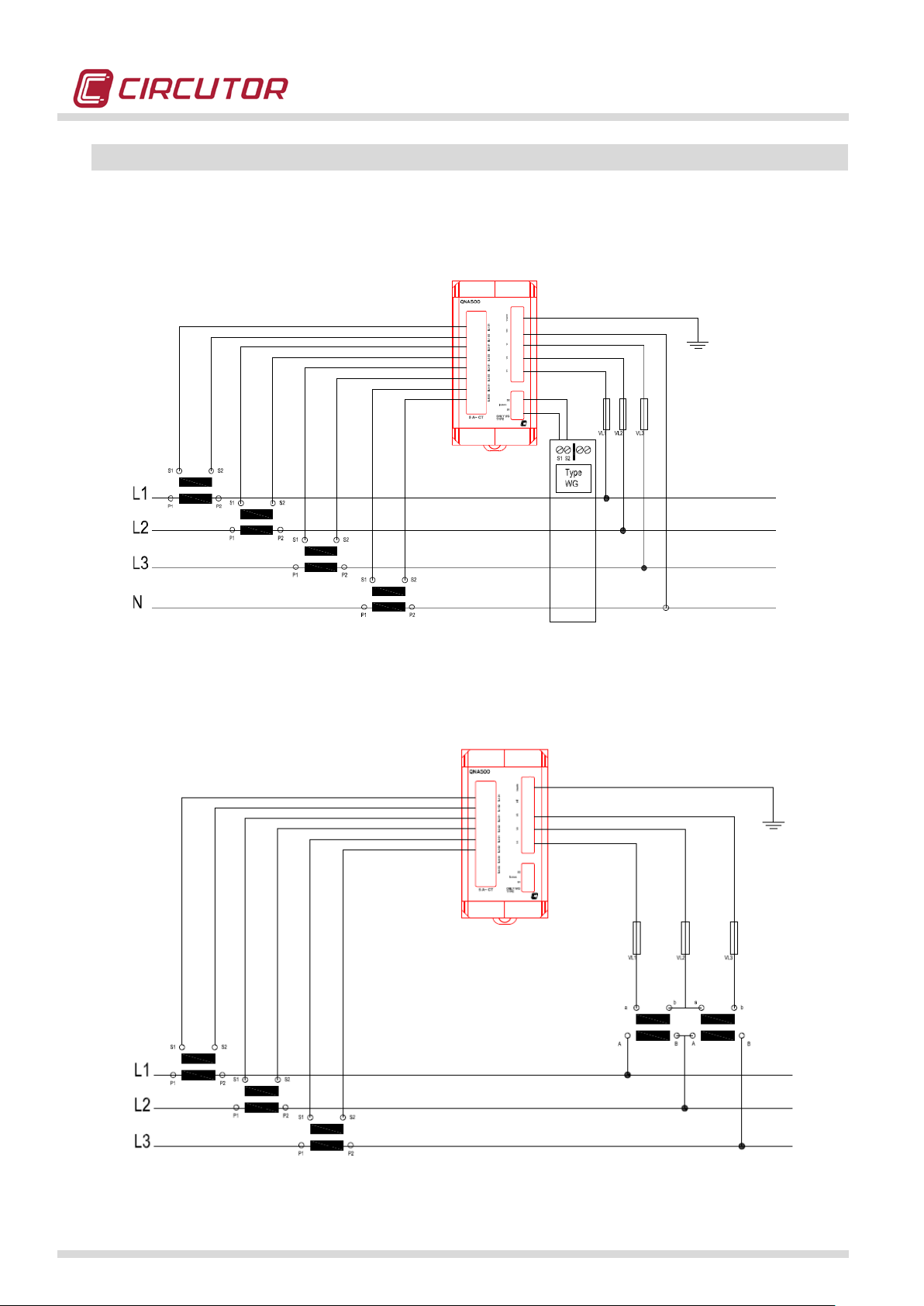
5.7.- MEASUREMENT CONNECTION DIAGRAMS
5.7.1.- 4 CURRENT TRANSFORMERS AND 5 VOLTAGE REFERENCES
5.7.2.- 3 CURRENT TRANSFORMERS AND 2 VOLTAGE TRANSFORMERS
QNA500 8IO Instruction manual
20 / 111
Page 21
POWER QUALITY ANALYZER QNA500 8IO
The equipment must be connected to a power circuit protected with gl-type
voltage measurement circuits are connected with a cable with a minimum
. (AWG 17). The current transformer's secondary
5.8.- CONNECTING POWER SUPPLY
The MULTIFIT system is powered with the M-BASE module. This power supply also powers all other
interconnected modules.
M-BASE power supply is powered with a connector with three terminals for power supply and
grounding purposes.
fuses, in compliance w ith IEC 269, or M-type, fro m 0.5 to 1A / 600 V ( UL listed ).
It must be fitted with a circuit b reaker switch or equivalent device, i n order to
be able to disconnect the device fro m the power sup ply. The power circu it and
cross-section of 1 mm
connection line must have a minimum cross-section of 2mm2. (AWG 14) and
withstand a minimum of 60ºC.
2
QNA500 8IO Instruction manual
21 / 111
Page 22
POWER QUALITY ANALYZER QNA500 8IO
ETH Link with external
sources
ETH Link with the next
module
6.- OPERATION OF THE QNA500 (MULTIFIT SYSTEM DESCRIPTION)
6.1.- Physical description
The QNA500 is a top performance power quality analyzer that is part of a new generation of products the MULTIFIT range. This innovative system can be used to add various modules to expand the
performance of the system while controlling the global electrical installation.
The QNA500 is com posed of an M-BASE power supply and communications module that can power
the set of modules and intercommunicate them through its internal bus. This optimises the installation,
since various modules can be connected in parallel to a single M-BASE b ase module. In addition, this
module can communicate with any other module via its RS-232, RS-485 or ETHERNET ports.
Likewise, the QNA500 can take electrical voltage (5 independent channels) and current measurements
(5 independent channels) to supervise the installation and to detect existing anomalies, with the
purpose of analysing it and carrying out predictive maintenance.
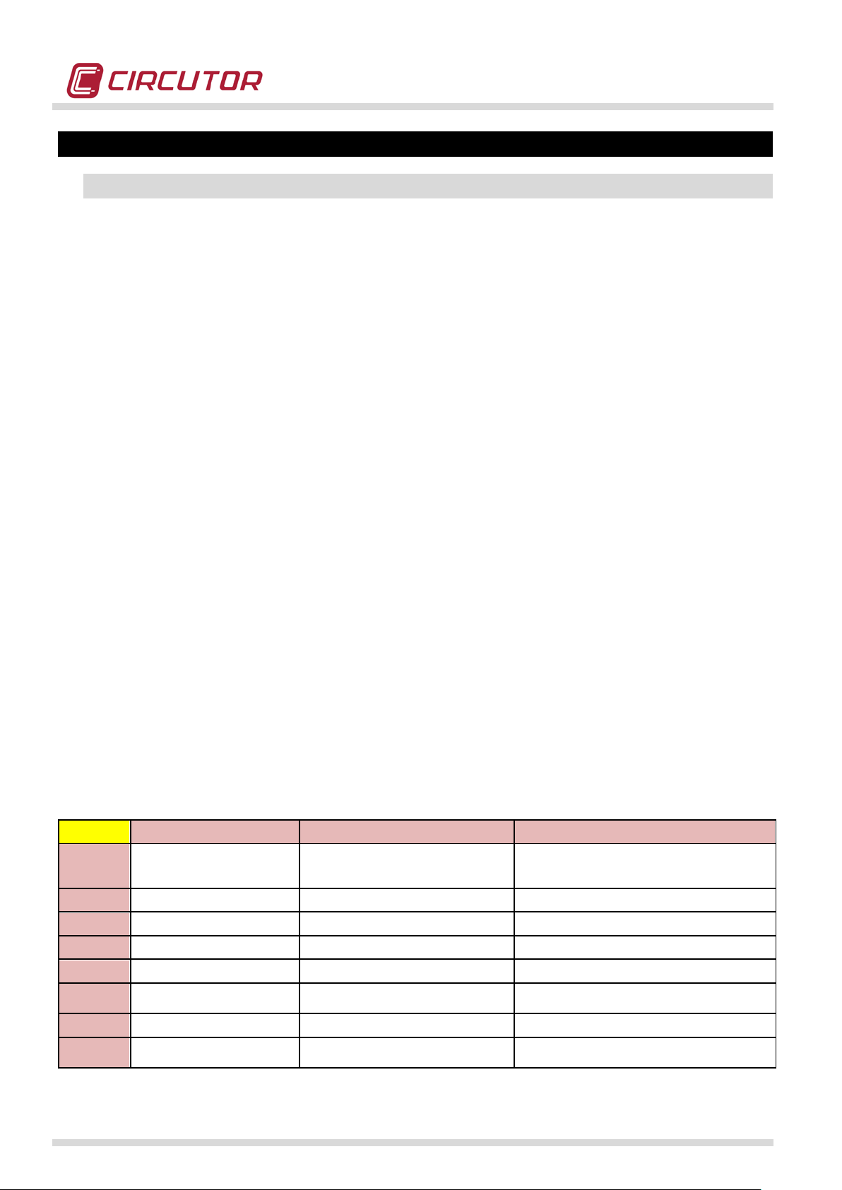
6.1.1.- BASE MODULE (M-BASE)
M-BASE is the main module of the MULTIFIT system. This module is vital in any combination with the
systems of the MULTIFIT range, since it is responsible for powering all other modules and establishing
the communications with external devices.
M-BASE has 3 communications ports that can communicate the information of the connected modules
to external devices and systems. The ports are as follows:
• RS-232
• RS-485
• ETHERNET (TCP/IP)
The 3 communications ports operate as independent systems. In other words, they can simultaneously
request information from all connected modules. M-BASE module has a series of LED indicators that
are used to show the correct operation of the power supply and communication systems.
LED Power off Power on Flashing
POW
STATUS
RS-232
RS-485
Act1
No power External power supply (1 sec.)
Battery power supply (200 ms)
No error Ethernet not initialised Memory error
Rest Data reception
Rest Data reception
No activity with external sources External TX/RX ETH activity established
Link1
Act2
Link2
QNA500 8IO Instruction manual
ETH No link with external sources
No activity with the next module TX/RX ETH activity with the next module
ETH No link with the next module
22 / 111
Page 23
POWER QUALITY ANALYZER QNA500 8IO
TX/RX ETH activity with the previous
module
ETH Link with the previous
module
ETH No link with the previous
module
LED indicator
Communications
ETHERNET
External power
lights
ports:
RS-485
RS-232
supply
6.1.2.- MEASUREMENT MODULE (QNA500)
QNA500 is the module that measures the electrical parameters of the MULTIFIT system. This module
has 5 voltage measurement channels, 4 current measurement channels and 1 earth leakage current
measurement channel.
QNA500 has a series of LEDs that provide information about the correct connections of the power
quality analyzer and its correct operation.
LED Power off Power on Flashing
POW
STATUS
Act1
Link1
No power External power supply (1 sec.)
Battery power supply (200 ms)
No error Ethernet not initialised Memory error
V
No measurement
I
No measurement
Correct connection: 3 balanced
voltages
Correct connection: 3 balanced
currents
No activity with the previous module
Incorrect connection: RMS voltages
Incorrect connection: RMS currents
Act2
Link2
ETH Link with the next connected
module
QNA500 8IO Instruction manual
No activity with the next module
ETH No link with the next connected
module
TX/RX ETH activity with the next
module
23 / 111
Page 24

POWER QUALITY ANALYZER QNA500 8IO
LED
Power off
Power on
Flashing
POW
No power
Powered
External power supply (1 s)
ST1
No errors
Memory error
ST2
No errors
Update in progress
Voltage
measurement
Earth-leakage
Current
measurement
current
Measurement
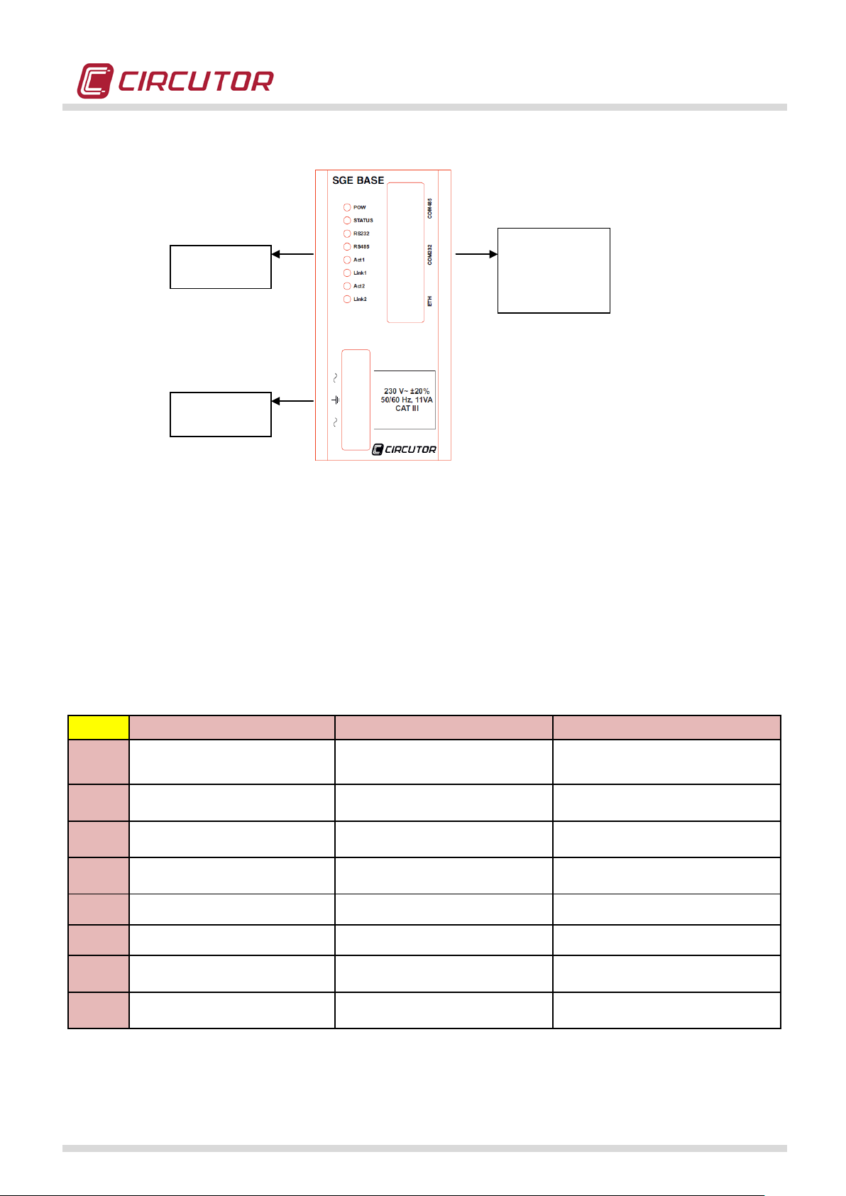
6.1.3.- INPUT-OUTPUT CENTRALIZER MODULE (M-8IO)
M-8IO is the input-output module of the MULTIFIT system. This module has 8 digital inputs and 8
digital outputs (relay or transistor, in accordance with the module) that can be used for various
functions.
Digital inputs:
• Pulse counter
• Status change control
Digital outputs:
• Pulse transfer
• Alarms
• Remote control
M-8IO has a series of LEDs that provide information about the correct connections of the analyzer and
its correct operation.
QNA500 8IO Instruction manual
Battery power supply (200 ms)
24 / 111
Page 25
POWER QUALITY ANALYZER QNA500 8IO
Make sure that all cables have been correctly connected before powering the
Power
Digital inputs
Digital outputs
Status
6.2.- Supply the power quality analyzer
equipment. The incorrect connection of the cables can cause serious inj uries to the
persons handling the equipment and damage to the equipment.
When the M-BASE module is powered, the equipment performs a series of checks associated to selfdiagnosis, connected module detection and verification of communications.
When the STATUS LED is off, the initialisation and module self-detection process will be complete and
successful.
Any anomaly or error detected during the st art-up of t he power quality analy zer must
be notified to CIRCUTOR SA technical service.
QNA500 8IO Instruction manual
25 / 111
Page 26

POWER QUALITY ANALYZER QNA500 8IO
7.- BASE MODULE SETUP (M-BASE)
The QNA500 analyzer can be configured with the software supplied by CIRCUTOR, using the
analyzer's WEB server or editing the Setup.XML file.
This file can be edited with non-proprietary software and can configure the analyzer, in accordance with
the installation's requirements.
The M-BASE module has been designed to power all other MULTIFIT modules connected to it,
establish communications with external devices via any of the 3 communications ports (RS-232, RS485 or ETHERNET) and act as an external and internal communications switch.
We recommend using an ETHERNET cable to configure the M-BASE module. Connect to the WEB
server hosted in this module with a PC f or such procedures. You can easily and quickly configure the
module in a few seconds.
(*) Refer to the corresponding software manual for more information related to the configuration of the
analyzer with the use of CIRCUTOR software.
(**) R efer to t he specific section in this manual for more information related to the configuration of the
analyzer with the use of the WEB Server.
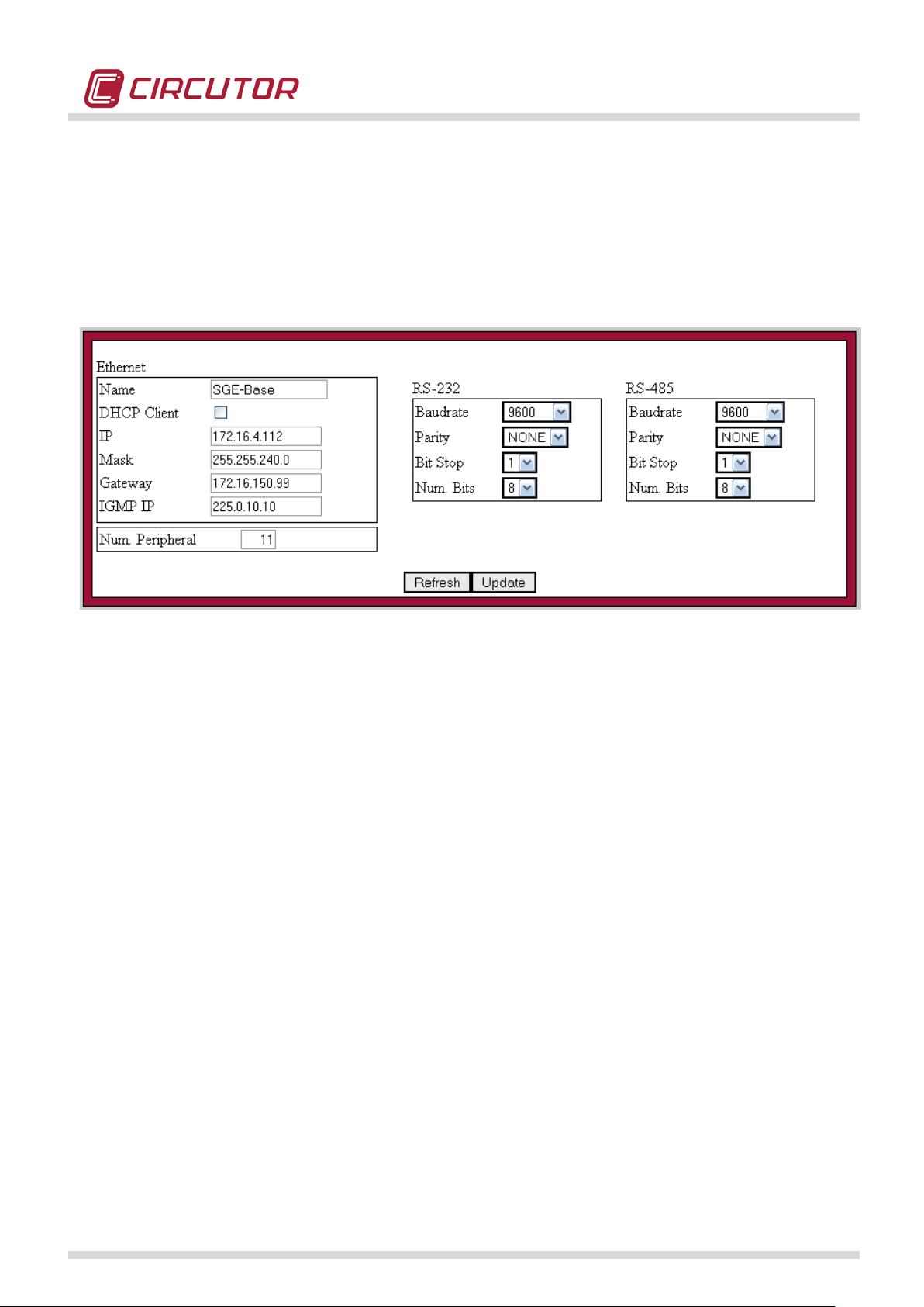
7.1.- COMMUNICATIONS
We recommend using the WEB server or software provided by CIRCUTOR to access the
communications setup menu of the M-BASE.
When using the Ethernet port, QNA500 8IO is configured with the DHCP option enabled. When it is
connected to an intranet with a DHCP server, the server will automatically assign an IP address to the
analyzer.
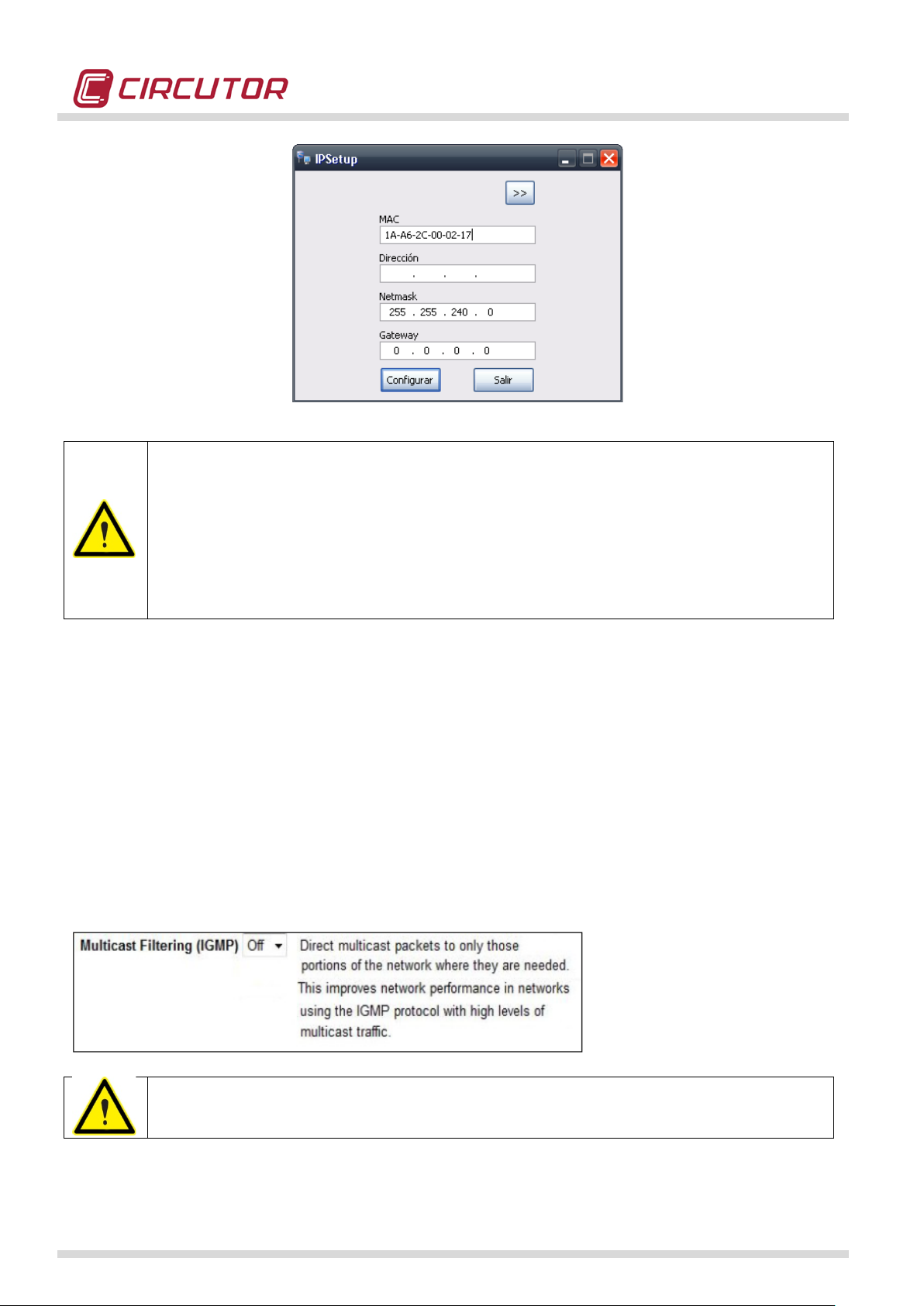
Use the IP Setup software supplied with the analyzer to know t he IP address assigned by the server or
assign a specific IP address. To do so, it is vital to know the MAC address shown on the silver
adhesive label attached to the top of the product.
The QNA500 analyzer's default configuration is as follows:
• (M-BASE): Peripheral no., speed - length - parity - stop bits: 1, 9600-8-N-1
• (QNA500 8IO): Peripheral no., speed - length - parity - stop bits: 2, 9600-8-N-1
The default configuration of the input-output module (M-8IO and M-8IOR) is as follows:
• (M-8IO): Peripheral no., speed - length - parity - stop bits: 10, 9600-8-N-1
• (M-8IOR): Peripheral no., speed - length - parity - stop bits: 10, 9600-8-N-1
All communications ports are MULTI-PROTOCOL, so that the port can communicate with all protocols
supported by the MULTIFIT system.
Available protocols:
QNA500 8IO Instruction manual
26 / 111
Page 27
POWER QUALITY ANALYZER QNA500 8IO
• MODBUT/RTU (on-line communications)
• MODBUS/TCP (on-line communications)
• CIRBUS (on -line communications of the question-answer type in the ASCII format)
• ZMODEM (partial or complete file download)
• HTTP (web protocol)
• FTP (complete file download)
The previous figure shows how the WEB server of the M-BASE module can be used to program its I P
address and configure the RS-232 and RS-485 ports.
7.1.1.- IP ADDRESS CONFIGURATION
Once the equipment has been installed in an IT network with a DHCP server, the server will
automatically assign an IP address to each MULTIFIT module. The IP address of each module must be
known to communicate with them or integrate them in an IT application.
To do so, CIRCUTOR supplies the IPSetup application, which can be used to assign a specific IP
address to each MULTIFIT module.
It is vital to know the MAC address shown on the silver adhesive label attached to the top of the
product before programming this IP address.
QNA500 8IO Instruction manual
27 / 111
Page 28
POWER QUALITY ANALYZER QNA500 8IO
In a LAN network, servers have the option to assign IP addresses with an expiration
ime is configurable on the server depending on the
request an IP address. If the server is not active at that time, or t he Ethernet cable is not
power quality analyzer has DHCP option enabled, is
avoid this situation.
time from hours to weeks. This t
target of the IT Administrator. After this time, the power quality analyzer must again
connected, IP address will be lost.
This means that if QNA500
mandatory to have Ethernet cable always connected and DHCP server always active to
7.1.1.- IGMP CONFIGUARTION
IGMP default address is 225.0.10.10.
This address allows to each module to detect others and to communicate between them. To allow
management actions and communications between modules is mandatory that all MULTIFIT modules
have same IGMP address.
User must take care of following requirements:
• All modules must have same IGMP IP address
• IGMP range is from 224.0.0.0 to 239.255.255.255
• If two modules have different IGMP IP addresses, they don’t detect each other and they cannot
send messages between them.
• If exists Ethernet switches in the LAN, these cannot have activated multicast message filters
Some industrial switch are provided with IGMP message filters. Keep in mind that if this
switches are activated, QNA500 won’t be able to send messages between modules.
QNA500 8IO Instruction manual
28 / 111
Page 29

POWER QUALITY ANALYZER QNA500 8IO
7.1.2.- NTP SYNCHRONIZATION
NTP synchronization allows to QNA500 modules to synchronize its clocks with milliseconds of
resolution.
This synchronization allows that many devices works with the same date and time, avoiding errors with
different time flags in data.
M-BASE is able to synchronize all modules connected to itself by activating this option. You can set up
to 2 different NTP servers, a primary server and an auxiliary server.
To configure NTP synchronization is mandatory to set-up following fields:
NTP IP: IP address of the NTP server.
NTP Port: port number of the NTP server.
Additionally, you can check if communication is working properly using ‘Get Time’. If communication is
working properly, you will see UTC Time. If not, you will see 00/00/00 00:00:00.
7.1.3.- DEVICE NUMBER CONFIGURATION
MULTIFIT system allows to assign a device number to each module and an IP address. Device
number must be unique in the bus and cannot be repeated by any-other MULTIFIT module or a device
in the RS485 connected to a M-BASE. If this happens, modules will detect a repeated device number
an communications won’t work correctly.
M-BASE works as a GATEWAY of other devices connected to the RS-485 port (i.e. power analyzers
CVM). It’s very important to check that these devices have different device number of the MULTIFIT
modules.
QNA500 8IO Instruction manual
29 / 111
Page 30

POWER QUALITY ANALYZER QNA500 8IO
8.- POWER QUALITY ANALYZER SETUP (M-QNA500)
The QNA500 power quality analyzer can measure the voltages and currents of the electrical
installation, with the purpose of achieving the global supervision and control of the whole installation.
The following sections describe the main configuration options and the configuration options.
8.1.- COMMUNICATIONS
To access to the setup it’s recommendable to use WEB-Server or software provided by CIRCUTOR.
In case of using ETHERNET port, QNA500 is setup with DHCP as default, so if this is connected to a
LAN network, DHCP server of this LAN will provide IP addresses to each module automatically.
To know assigned IP address, or to assign an specific IP address, you can use IP setup software,
which ask you MAC address and allows you to set an specific IP to each module.
By default, QNA500 has following configuration:
• (QNA500): Device Number, Baud Rate, Length, Parity, Stop Bits: 2, 9600-8-N-1
All communication ports are MULTIPROTOCOL which means that you can communicate using any of
the supported protocols.
Available protocols are the following:
• MODBUS/RTU (on-line communications)
• MODBUS/TCP (on-line communications)
• CIRBUS (on-line communications)
• ZMODEM (protocol to download files)
• FTP (protocol to download files)
• HTTP (protocol to connect using Web-Browser)
8.2.- MEASUREMENT
The following measurement parameters can be configured:
TRANSFORMATION RATIOS:
• Voltage Primary / Voltage Secondary: It will be programmed in accordance with the voltage
transformer ratio used to take the measurement. Direct measurements must be programmed to
1/1. This ratio must not exceed 9999. Maximum primary and secondary values are 500000 and
999,9 respectively.
• Current primary: The current transformer primary used to measure the current will be
programmed. Maximum primar y value is 10000.
• Current secondary: The current transformer secondary used to measure the current will be
programmed (default: 5 A).
QNA500 8IO Instruction manual
30 / 111
Page 31

POWER QUALITY ANALYZER QNA500 8IO
• Neutral Current Primary: The current transformer primary used to measure the neutral current
will be programmed.
• Primary VT * Primary CT ratios: Maximum primary value of VT multiplied by primary
value of CT must be lower than 2000000000
NOMIN AL VALUES
• Nominal Voltage: Corresponds to the nominal voltage measured by the power quality analyzer.
In the ca se of t he 3-wire configuration, the phase-phase voltage must be programmed (e.g. 400
V), and the phase-neutral voltage must be programmed for 4-wire configurations (e.g. 230 V).
When the measurement is recorded through the voltage transformers, the nominal voltage must
be programmed so that it is referred to the secondary (e.g. 63.5 V). This value is vital for the
correct recording of events.
• Nominal Current: Corresponds to the nominal current being measured by the analyzer, which
will be used to establish the maximum and minimum % to record disturbances. The default
value is 5 A. The value used to program measuring transformers is recommended.
• Nominal Frequency: Nominal frequency of the network being analyzed. This parameter is
required to calculate the effective value of the signal in top quality networks.
TYPE OF CONNECTION
• 3-wire / 4-wire: QNA500 8IO is prepared for an operation in installations with a neutral (4-
wires) or installations without a neutral (3-wires). The type of connection is defined at this point.
This is important, since the value programmed for this variable will be used to detect and record
voltage events. When programmed for 4-wires, all measurements will be taken from phaseneutral, and when programmed for 3-wires, the reference values will be phase-phase.
MEASURING POINT
• Description: This field is only used for identification purposes by the user.
• Comments: This field is only used for information purposes by the user.
QNA500 8IO Instruction manual
31 / 111
Page 32

POWER QUALITY ANALYZER QNA500 8IO
8.3.- POWER QUALITY
The voltage levels must be defined to calculate the power quality events.
• % Overvoltage threshold: Overvoltage detection depends on the value programmed in this
section. Any semi-cycle with an RMS value that exceeds this threshold (% over the nominal
voltage) will be understood as an overvoltage. The events file (EVQ) will save a record when
this value is exceeded, stating the phase, maximum voltage recorded, mean voltage, voltage
before the event occurred and the time during which this threshold has been exceeded.
• Overvoltage hysteresis: An overvoltage hysteresis will be defined so that the event start
voltage is not the same as the event end voltage. Therefore, an overvoltage starts when the
semi-cycle voltage exceeds the overvoltage threshold and ends when it goes below the said
threshold + the hysteresis programmed for this threshold.
• % Sag threshold: Sag detection depends on the value programmed in this section. Any semi-
cycle with an effective value that does not reach this threshold (% over the nominal voltage) will
be understood as a sag. The events file (EVQ) will save a record each time this value is not
exceeded, stating the minimum voltage recorded, mean voltage and the time during which this
threshold was not exceeded.
• Sag hysteresis: A sag hysteresis will be defin ed so tha t the s ag start vo ltage is n ot the same
as the sag end voltage. Therefore, a sag is started when the voltage does not exceed the sag
threshold and it ends when this threshold is exceeded + the hysteresis programmed for this
threshold.
• % Interruption threshold: Interruption detection depends on the value programmed in this
section. Any semi-cycle with an effective value that does not reach this threshold (% over the
nominal voltage) will be understood as an interruption. The events file (EVQ) will save a record
each time this value is not exceeded, stating the minimum voltage recorded, mean voltage and
the time during which this threshold was not exceeded.
• Interruption hysteresis: An interruption hysteresis will be defined so that the interruption start
voltage is not the same as the interruption end voltage. Therefore, an interruption is started
when the voltage does not exceed the interruption threshold and it ends when this threshold is
exceeded + the hysteresis programmed for this threshold.
8.4.- TRANSIENTS
QNA500 can detect transients, according to different conditions. Transients can be detected in
accordance with 2 different conditions:
The following variables must be configured to record the transients:
1. Semi-cycle RMS value: RMS value of each cycle is calculated, updated each semi-cycle, and
compared with the maximum and minimum values programmed by the user. When the
maximum or minimum RMS value is exceeded, this is considered the moment when a tr ansient
or disturbance is set off. We advise setting the maximum or minimum values far from the
nominal value existing in the installation. Otherwise, the analyzer will record many different
transients that will not be relevant in a future user analysis.
QNA500 8IO Instruction manual
32 / 111
Page 33

POWER QUALITY ANALYZER QNA500 8IO
2. dV/dt detection (ramp met hod): This detection is achieved by comparing the measured wave
shape with an ideal wave shape. Each one of the 512 samples is compared to the previous
sample; when this value exceeds the value of the maximum ramp calculated for each point, the
system will consider that a transient or disturbance has been generated, depending on the
sensitivity selected by the user. The maximum ramp is the tangent calculated for each point of
the sine wave.
Rm = Vp * w/oϕ * trigger level
The following variables must be configured to record the wave shape:
• Nº pre-trigger cycles: Number of cycles registered before activating the record (1 to 10.
Default: 5)
• Nº. post-trigger cycles: Number of cycles registered after activating the record (1 to 50.
Default: 15)
• Trigger level (maximum ramp detection): Value that determines the transient detection
sensitivity level. Th e value entered must be from 1 to 100.
When the sensitivity value entered is very low, the analyzer will be very sensitive when
detecting transients. On the other hand, when the sensitivity value entered is very high, the
deformation of the signal must be greater for the analyzer to start detecting it.
• Maximum and minimum effective comparison values (RMS system): A maximum and
minimum voltage / current percentage must be programmed, when compared to the nominal
value.
The trigger is activated when the effective value of a cycle updated each semi-cycle exceeds
the maximum value or is under the minimum programmed value.
• Trigger variables: Variable or variables that will trip the trigger, in accordance with the
conditions described above. The trigger is activated by the f irst programmed variable that meets
the conditions when more than one variable is programmed.
The transient will be recorded in the COMTRADE format (according IEEE C37.111) and the data will
be saved in the WAVE directory of the memor y. The waveform of the 4 voltage and current channels
(P1, P2, P3, N) will be stored for each disturbance detected. The memory record is stored at 204
samples per cycle.
The date of the last disturbance detected can be checked to guarantee the correct configuration of the
transient setup, adjusting the most adequate sensitivity degree for the installation.
The same configuration can be easily and quickly saved with CIRCUTOR's PC software.
8.5.- REMOVE FILES
Records can be deleted from the MULTIFIT system through the WEB server or the software supplied
by CIRCUTOR.
Refer to the specific section in this manual for more information about deleting records via the WEB
server. This action deletes all files associated to the measurements taken by the analyzer.
QNA500 8IO Instruction manual
33 / 111
Page 34

POWER QUALITY ANALYZER QNA500 8IO
8.6.- CLOCK
Make sure that the correct time has been pr ogrammed before the analyzer's programming pr ocedures
have been completed. Use the analyzer's WEB server (see corresponding section) or the specific
CIRCUTOR software to make sure that the correct time has been programmed in the analyzer.
QNA500 offers the Local Time or UTC Time options.
8.7.- BATTERY
M-BASE module has an internal battery that can be used to power all connect ed modules. The m ain
purpose of this battery is to make sure that all modules continue to operate during a limited period of
time in case there is an interruption in the electric supply.
The most common function entails storing voltage sags or interruptions, and moreover keep active the
communication with the device or perform certain operations (activate/deactivate loads).
The main feature of the product s of t he MULTIFIT range is based on the connection of said products to
the same M-BASE module, which will operate as independent products. The battery can power the
modules connected to the system during a period of time configured by the user. The default time is 1
minute and it can be configured to up to 15 minutes. The M-BASE module can power a maximum of 2
QNA500 modules + 1 M-8IO module simultaneously with the battery.
8.8.- STANDARD RECORDING PERIOD
The recording period shows the number of minut es that QNA500 8IO uses to create a new register in
the memory. All electrical parameters will be recorded (only those selected) at the end of the
programmed time. Average, maximum and minimum values obtained during this period of time will be
recorded. The default recording time is 10 minutes. This value can be modified to a period of between
1 minute and 2 hours. This time only affects the data file (.STD).
8.9.- ENERGY RECORDING PERIOD
The recording period shows the number of minutes that QNA500 8IO uses to create a new register with
energy values in the memory.
8.10.- SELECTING VARIABLES TO BE RECORDED
QNA500 analyzer can be used to select the variables that will be recorded. These variables can be
selected via the WEB server (see the corresponding section in this manual) or via specif ic CIRCUTOR
software.
QNA500 8IO Instruction manual
34 / 111
Page 35

POWER QUALITY ANALYZER QNA500 8IO
Variable description
Variable code
L1 Voltage
1
L2 Voltage
2
L3 Voltage
3
N-G Voltage
4
Voltage III
5
L1-L2 Voltage
10
L2-L3 Voltage
11
L3-L1 Voltage
12
L1 Current
20
L2 Current
21
L3 Current
22
Neutral Current
23
Current III
24
L1 Active Power
30
L2 Active Power
31
L3 Active Power
32
III Active power
33
L1 Inductive Power
35
L2 Inductive Power
36
L3 Inductive Power
37
III Inductive Power
38
L1 Capacitive Power
40
L2 Capacitive Power
41
L3 Capacitive Power
42
III Capacitive Power
43
L1 Apparent Power
45
L2 Apparent Power
46
L3 Apparent Power
47
III Apparent power
48
Angle V1-V2
60
Angle V2-V3
61
QNA500 analyzer will record all variables selected every X minutes once the variables have been
selected and the new configuration has been sent, in accordance with the programmed standard
recording time period.
These records are saved in various files, depending on the type of data. Refer to the file section for
more information related to the location of these information records.
8.11.- ALARM SETUP (Digital objects)
QNA500 power q uality analyzer can configure a list of alarms (up to 16 alarms) for an improved and
more accurate supervision of the electrical installation and its status.
These alarms can be simply recorded in the memory or used to create actions in other MULTIFIT
modules, such as, for example, the activation of the relay of a M-8IO module.
There are 2 different types of alarms (or digital objects), as described:
• ALARM OBJECTS: can enable any alarm condition associated to an electrical variable
measured by the QNA500 module.
• ENERGY OBJECTS: these are necessary when associating a pulse output of a M-8IO module.
The most common application is where the pulse outputs can produce pulses proportional to
the energy (A+, A-, Q1, Q2, Q3 or Q4) measured by the QNA500. To do so, first activate an
energy object and activate the pulse output on the M-8IO module. This configuration is
explained in the corresponding chapter of this module.
These alarms (or digital objects) can be associated with the following variables:
QNA500 8IO Instruction manual
35 / 111
Page 36

POWER QUALITY ANALYZER QNA500 8IO
Angle V1-I1
65
Angle V2-I2
66
Angle V3-I3
67
L1 Power Factor
70
L2 Power Factor
71
L3 Power Factor
72
III Power Factor
73
L1 Cos fi
75
L2 Cos fi
76
L3 Cos fi
77
III Cos fi
78
Unbalance V
90
Asymmetry V
91
Unbalance I
92
Asymmetry I
93
THD VL1
100
THD VL2
101
THD VL3
102
THD Vn-G
103
THD IL1
105
THD IL2
106
THD IL3
107
THD In
108
Active Energy
120
Reactive Energy L
121
Reactive Energy C
122
Active Energy -
130
Reactive En. L-
131
Reactive En. C -
132
Flicker L1
140
Flicker L2
141
Flicker L3
142
Earth leakage current
150
Frequency
160
Transient
170
Active energy T1
171
Reactive energy L T1
172
Reactive energy C T1
173
Active energy – T1
174
Reactive energy L- T1
175
Reactive energy C – T1
176
Active energy T2
177
Reactive energy L T2
178
Reactive energy C T2
179
Active energy – T2
180
Reactive energy L- T2
181
Reactive energy C – T2
182
Active energy T3
183
Reactive energy L T3
184
Reactive energy C T3
185
Active energy – T3
186
Reactive energy L- T3
187
Reactive energy C – T3
188
Active energy T4
189
Reactive energy L T4
190
Reactive energy C T4
191
Active energy – T4
192
Reactive energy L- T4
193
Reactive energy C – T4
194
Active energy T5
195
Reactive energy L T5
196
Reactive energy C T5
197
Active energy – T5
198
Reactive energy L- T5
199
Reactive energy C – T5
200
Active energy T6
201
Reactive energy L T6
202
Active energy – T6
204
Reactive energy L- T6
205
Reactive energy C – T6
206
Active energy T7
207
Reactive energy L T7
208
Reactive energy C T7
209
Active energy – T7
210
Reactive energy L- T7
211
Reactive energy C – T7
212
Active energy T8
213
Reactive energy L T8
214
Reactive energy C T8
215
Active energy – T8
216
Reactive energy L- T8
217
Reactive energy C – T8
218
Active energy T9
219
Reactive energy L T9
220
Reactive energy C T9
221
Active energy – T9
222
Reactive energy L- T9
223
Reactive energy C – T9
224
QNA500 8IO Instruction manual
36 / 111
Page 37

The following additional conditions can be assigned to each variable:
When this instruction is sent, the analyzer will delete the current data file and the
existing configuration will be lost. You must make sure that this process is going to be
• Maximum Value
• Minimum Value
• Activation Delay (in seconds)
• Deactivation Delay (in seconds)
• Memory record (Yes/No)
• Mail Group (no, group 1, …, group 4)
Once all desired alarms have been configured, the QNA500 8IO network power quality analyzer will
permanently monitor whether the conditions of one of the programmed alarms are met or not. If this is
the case, it will generate a memory record (if programmed as such), indicating the date when the alarm
was triggered.
In addition, in case the user considers that it is important to send the notification of the alarm detected
in a different MULTIFIT module, this option can be used to perform actions on the installation, such as,
for example, closing a relay for signalling purposes.
8.12.- FACTORY PRESETS
If you wish to program the configuration values again due to an initial error, the analyzer can be
configured with the factory presets, which will load the default programming.
carried out, since it does not offer the option of retrieving former values.
Page 38

POWER QUALITY ANALYZER QNA500 8IO
Registry variables
Unit
L1
L2
L3
III
Phase-phase and phase-neutral voltage (average,
V
X X X
X
Current (average, maximum, minimum)
A
X X X X Neutral current (average, maximum, minimu m)
A
X Earth-Leakage current (average, maximum, minimum)
A
X Neutral Ground voltage (average, maximum, minimum)
V
X Frequency (average, maximum, mini mu m )
Hz
X X X Active power (average, maximum, mini mum)
kW
X X X X Inductive reactive power (average, maximum, min imum)
kvar
X X X X Capacitive reactive power (average, maximum, min imum)
kvar
X X X X Apparent power (average, maximum, minimum)
KVA
X X X X Maximum demand
kW
X X X Power factor (average, maximum, mini mum)
X X X X Crest factor (voltage and current)
V or A
X X X K Factor
X X X Active energy
kWh
X X X X Inductive reactive energy
kvarh
X X X X Capacitive active energy
kvarh
X X X X Voltage THD (average, maximum, minimu m)
%
X X X X Current THD (average, maximum, minimum))
%
X X X X Voltage harmonics (up to 50th order)
V Harm
X X X X Current harmonics (up to 50th order)
A Harm
X X X X Voltage interharmonics (up to 50th order)
V Harm
X X X X Current interharmonics (up to 50th order)
A Harm
X X X
X
8.13.- RECORDING FILES
QNA500 power quality analyzer records different files, in accordance with the type of data (voltage,
events, energy, etc).
The power quality analyzer records the following files:
8.13.1.- .STD FILE
The Standard File (STD) is used to store all parameters that are stored periodically.
The records will be stored with the following electrical parameters (depending on the selection),
respecting the recording period programmed with the analyzer:
maximum, minimum)
QNA500 8IO Instruction manual
38 / 111
Page 39

POWER QUALITY ANALYZER QNA500 8IO
Flicker (PST)
X X X Voltage Unbalance
X Voltage asymmetry
X Current Unbalance
X Current asymmetry
X
The variable recording period can be configured by the user.
FLICKER:
• Pst: QNA500 analyzer will record the Flicker value (Pst) obtained during the recording period.
The Plt value is calculated with the PC's analysis software Flicker is defined as t he variation of
the RMS value or amplitude of the voltage within a range of less than 10% of the nominal value.
This variation in voltage amplitude produces a fluctuation of the luminous flux in lamps, at the
same time inducing a sensation of visual instability (visual flashing effect).
HARMONICS:
• Harmonic Distortion: QNA500 anal yzer measures, calculates and records the mean harmonic
distortion of the voltage and current detected from the analyzed network.
• Individual Harmonics: QNA500 analyzer measures, calculates and records the mean value of
the individual harmonic distortion rate of each voltage and current harmonic from the analyzed
network (up to the 40th harmonic). (Breakdown of each 10-cycle block integrated in a recording
period).
INTERHARMONICS:
QNA500 measure and register voltage and current interhamornics. These are signals introduced in the
power cable with frequencies non-multiple of the fundamental frequency (50 or 60Hz). QNA500 is able
to measure up to interharmonic 50, corresponding to signals with frequency of 2525Hz.
UNBALANCE:
• Voltage unbalance coefficient (Kd): homopolar and direct voltage ratio.
• Voltage asymmetry coefficient (Ka): inverse and direct voltage ratio.
QNA500 8IO Instruction manual
39 / 111
Page 40

POWER QUALITY ANALYZER QNA500 8IO
• Current asymmetry coefficient (Kd): homopolar and direct current ratio.
• Current unbalance coefficient (Ka): inverse and direct current ratio.
K FACTOR:
K Factor is a transformer power reduction factor. The losses generated by harmonics are taken into
account when calculating the K Factor.
It is always higher than the unit in installations with non-linear loads.
e: represents the transformer's copper loss and iron loss ratio. This value can be obtained from the
transformer test data or, alternatively, an approximate value of 0.3 can be used.
q: exponent with a value between 1.7 and 1.8.
CREST FACTOR:
The Crest Factor is equal to the amplitude of the wave shape peak divided by the RMS value. The
crest factor is calculated to provide the analyst with a quick idea of the impact on the wave shape. The
impact is constantly associated with the wear of the roller bearing, cavitation and wear of the gear
cogs, etc.
The crest factor is an important measurement associated to the status of the machine and it analyses
the wave shape, which would not be visible with the calculation of the harmonic distortion rate alone.
QNA500 8IO Instruction manual
40 / 111
Page 41

POWER QUALITY ANALYZER QNA500 8IO
Registry variables
Unit
L1
L2
L3
III
Active energy
kWh
X X X X Inductive reactive energy
kvarh
X X X X Capacitive active energy
kvarh
X X X
X
It is a perfect sine wave, with a "1" amplitude", RMS value equal to 0.707, so that the crest factor is
equal to 1.41. A perfect sine wave has no impacts and, therefore, the crest factor with a value of over
1.41 means that there is a certain impact degree.
8.13.2.- .WAT FILE
The variable recording period can be configured by the user and is different to the recording period of
an .STD file.
8.13.3.- .EVQ FILE
Events detected are stored in this file. The following data are stored from each one of the events:
• Event Type: Overvoltage, Sag or Interruption.
• Event Date: Date the event occurred. This value is obtained with a ½ Cycle accuracy.
• Event Type: This is stored when the event detected is an interruption, sag or overvoltage.
These events are defined in accordance with the specifications programmed in the QNA500.
The type of event also identifies the phase at which the event occurred.
• Duration of the Event: Duration of the event in milliseconds.
• Maximum/minimum voltage of the Event: When an interruption or sag is produced, the
minimum RMS½(*) voltage value obtained during the event will be stored. The maximum value
will be stored in the event of an overvoltage.
• Average voltage of the event: Average RMS½(*) voltage value obtained during the duration of
the recorded event.
• Voltage before the event: The RMS½* voltage value just before the event was produced will
be stored.
(*) ½ cycle RMS value: effective value of a complete cycle, refreshed every half cycle.
QNA500 8IO Instruction manual
41 / 111
Page 42

POWER QUALITY ANALYZER QNA500 8IO
8.13.4.- .EVA FILE
This file stores any event that is not related to the power quality analyzer's measurements, such as, for
example, a setup modification, change of time, power supply interruption or deleted files. Therefore,
this file is an incident registry file that acts as an analyzer's supervisor and as a filter against access to
the analyzer.
QNA500 can detect and record the following events, among others:
• Battery Off: It will state the moment when the QNA500 has stopped operating. T his moment
depends on the value programmed for the equipment to work with the internal battery when
there has been an interruption in the auxiliary power supply.
• Power Supply On: Indicates the moment when the power supply is connected to the QNA500
power quality analyzer.
• Power Supply Off: Indicates the moment when the power supply is disconnected from the
QNA500 8IO. The power quality analyzer is powered with the battery at this moment.
• Modified Setup: Records the moment when the analyzer's setup is modified.
• Memory Format: Moment when the user has initialised the internal memory of the QNA500
power quality analyzer.
• Internal memory and force format: An internal memory error has been detected and the
QNA500 analyzer will automatically initialise the whole memory.
• Delete File: Moment when the user has deleted a file from the internal memory of the QNA500
analyzer. When the first piece of data appearing in the .EVE file is the deletion of a file, this
means that the events file has been deleted.
• Change of Time: The equipment's time or date has been changed. This event must be
detected, since hourly modifications between measurements often correspond to time changes.
8.13.5.- .CFG AND .DAT FILES
These files store each transient recorded with the QNA500 power quality analyzer. The information
associated with each transient is composed of a .CFG file and .DAT file.
The format of these files follows the COMTRADE international standard (Common Format for Transient
Data Exchange for power systems), which is a file format for oscillographic data. This protocol is
frequently used by companies for recording oscilloscopes and simulations related to the design of highvoltage substations. The format of the COMTRADE file has been standardised by the IEEE.
QNA500 8IO Instruction manual
42 / 111
Page 43

POWER QUALITY ANALYZER QNA500 8IO
9.- INPUT/OUTPUT MODULE SETUP (M-8IO)
M-8IO centralizer module can supervise and control an electrical installation. The M-8IO module can
manage states, alarms and perform energy metering procedures with the use of programmable digital
inputs and outputs, managing the energy pulses received from other installation devices.
In addition to the power of the measurement module, QNA500 can interact with any electrical
magnitude present in the installation, making it easier to control the electrical installation.
M-8IO centralizer module has a built-in WEB server that allows the user to easily and quickly configure
the system from any PC with a WEB browser (for example, Internet Explorer, Mozilla or Chrome,
among others).
Before starting with the setup of alarms and other features, you must be sure that communications are
correctly configured in this module.
9.1.- COMMUNICATIONS
To access to the setup it’s recommendable to use WEB-Server or software provided by CIRCUTOR.
In case of using ETHERNET port, QNA500 is setup with DHCP as default, so if this is connected to a
LAN network, DHCP server of this LAN will provide IP addresses to each module automatically.
To know assigned IP address, or to assign an specific IP address, you can use IP setup software,
which ask you MAC address and allows you to set an specific IP to each module.
By default, M-8iO centralizer has following configuration (depending on model):
• (M-8iO): Device Number, Baud Rate, Length, Parity, Stop Bits: 10, 9600-8-N-1
• (M-8iO-R): Device Number, Baud Rate, Length, Parity, Stop Bits: 10, 9600-8-N-1
All communication ports are MULTIPROTOCOL which means that you can communicate using any of
the supported protocols.
Available protocols are the following:
• MODBUS/RTU (on-line communications)
• MODBUS/TCP (on-line communications)
• CIRBUS (on-line communications)
• ZMODEM (protocol to download files)
• FTP (protocol to download files)
• HTTP: (protocol to connect using Web-Browser)
QNA500 8IO Instruction manual
43 / 111
Page 44

POWER QUALITY ANALYZER QNA500 8IO
9.2.- Digital inputs
M-8iO centralizer module has 8 digital inputs. These inputs are designed to provide 2 main functions:
• Pulse counting: can be wired up to 8 meters (or other devices) send to send pulses
proportional to measures of physical quantities and M-8iO module will count the number of
pulses and group them in a registration period as a load profile of pulses received.
• Registration status changes (On / Off): T his option allows to record the date / time that an
input is activated and / or deactivated. In the case of circuit breakers or other elements of a
plant want to be aware when they are fired, only one auxiliary contact wiring to the
corresponding input, this option would be recorded.
The digital inputs are capable of detecting pulses of minimum width of 15μs.
The configuration of the digital inputs and monitoring can be done via the web server of the module.
NOTES:
• For more information on configuring the module using the M-8iO web server, see the section
'Web Se rver'.
• For more technical information on the digital inputs, see the section on 'Technical
Characteristics'.
9.3.- Digital outputs
There are 2 models with 8 digital outputs and the difference relays or opto-mosfet. M-8iO centralizer
module has 8 opto-MOSFETs, while the module M-8iOR has 8 relays.
These outputs are designed to provide 4 main functions:
• Pulse proportional to energy (M-8iO): This option allows you to program one or more outputs
to generate pulses proportional to the energy measured by the module QNA500.
• Alarms: T his option allows you to open/close a digital output depending on an electric variable
measured by the analyzer QNA500, or an alarm conditional on a change of state of a digital
input module or another module itself M-8iO.
• Remote Control: Allows you to open or close a digital output at the user, without being subject
to any pre-programmed condition.
• Time operations: this option allows to open/close outputs depending on time conditions. As an
example it’s possible to connect some loads at one specific time and to disconnect them at
some other specific time.
The digital output configuration and monitoring can be done via the web server of the module.
QNA500 8IO Instruction manual
44 / 111
Page 45

POWER QUALITY ANALYZER QNA500 8IO
Register variables
Pulses input 1
Pulses input 2
Pulses input 3
Pulses input 4
Pulses input 5
Pulses input 6
Pulses input 7
Pulses input 8
NOTES:
• For more information on configuring the module using the M-8iO web server, see the section
'Web Se rver'.
• For more technical information on the digital inputs, see the section on 'Technical
Characteristics'.
9.4.- Files
M-8iO module creates two different files to record information of the energy pulses and status changes
or alarms created.
Files can be downloaded from WEB server or using software CIRCUTOR.
9.4.1.- .STD FILE
Register period can be set by user.
9.4.2.- .EVA FILE
This file stores any change in status of the digital outputs provided by an alarm, or a change in status of
the digital inputs produced by the opening / closing of an external relay.
Each time there is one of these changes, there is a record of date, time and type of alarm
QNA500 8IO Instruction manual
45 / 111
Page 46

POWER QUALITY ANALYZER QNA500 8IO
Variable description
Code
Digital Input 1
101
Digital Input 2
102
Digital Input 3
103
Digital Input 4
104
Digital Input 5
105
Digital Input 6
106
Digital Input 7
107
Digital Input 8
108
9.5.- ALARM SETUP (Digital objects)
M-8iO centralizer can configure a list of alarms (up to 16 alarms) to manage conditions f rom itself or
from other MULTIFIT modules.
These alarms can be recorded in the memory, used to create actions in other MULTIFIT modules or to
open/reclose digital outputs in the M-8iO centralizer.
There are 3 different types of alarms (or digital objects), as described:
• ALARM OBJECTS: can enable any alarm condition associated to an electrical variable
measured by the QNA500 module.
• ENERGY OBJECTS: these are necessary when associating a pulse output of a M-8IO module.
The most common application is where the pulse outputs can produce pulses proportional to
the energy (A+, A-, Q1, Q2, Q3 or Q4) measured by the QNA500. To do so, first activate an
energy object and activate the pulse output on the M-8IO module. This configuration is
explained in the corresponding chapter of this module.
• TIME OBJECTS: these objects allows to open/reclose a digital output depending on a time
condition.
These alarms (or digital objects) can be associated with the following variables:
These alarms can be linked with others by using conditions (AND, OR, AND NOT, OR NOT).
Moreover, each alarm can be used in a negative or positive logic. Finally, for each alarm user can do
following actions:
• Regist er ala rm in mem ory (with time-stamp)
• Open/reclose digital output (relay or opto-mostfet)
• Send confirmation to other centralizer MULTIFIT (up to 4 modules)
• Send emails (no-emails , list 1,…, list 4)
QNA500 8IO Instruction manual
46 / 111
Page 47
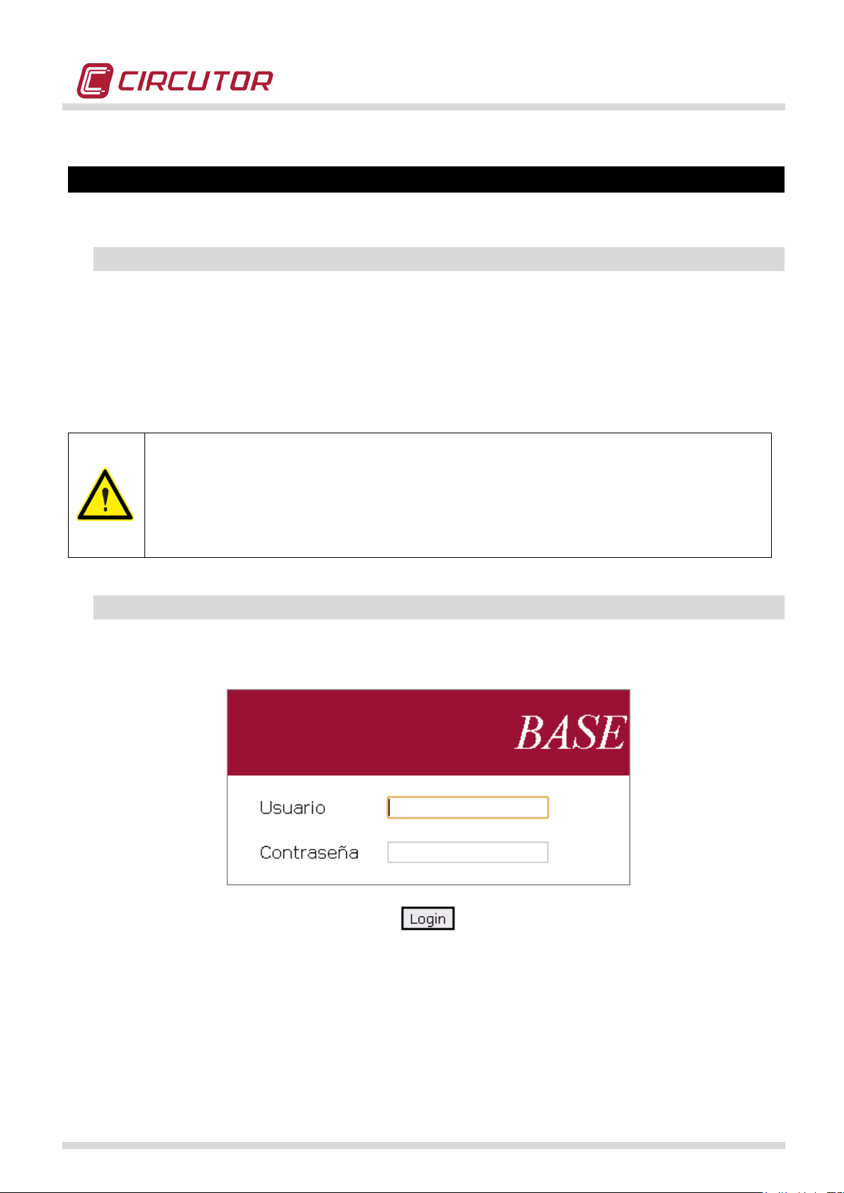
POWER QUALITY ANALYZER QNA500 8IO
Web server access is tested with standard web browsers. It is very important that
reception privileges in order to allow a
servers allows correctly following
from mobile phone or tablet (Safari from iOS, Opera for Blackberry, Chrome for
Android devices).
10.- WEB SERVER
10.1.- Introduction
Each module of the MULTIFIT system has an independent WEB server that can monitor and
configure the data with a flexible approach. The user can access each independent WEB server
and check any type of data. The WEB server has a connection time-out. The server will close
the connection and request the user and password again after 2 minutes with no activity.
Each web-server allows access to 2 users. First one is ‘root’ which have privleges of writingreading and second one is ‘user’ which has only reading privileges.
web browser used has enabled cookies
correct access to the server.. MULTIFIT webweb browsers: from PC (Internet Explorer, Mozilla Firefox, Google Chrome) and
10.2.- M-BASE Setup
The initial configuration window requests the user to enter a user name and pass wor d to access the
server of the M-BASE module.
The default user names and password of the 2 types of user are as follows:
Root user and password: r oot & cir-root
Guest user and Password: user & cir-user
QNA500 8IO Instruction manual
47 / 111
Page 48

The WEB server has a menu with the following functions:
Monitor
Setup
system
Logout
Measure
Quality
Files
Modules
Communications
Clock
Syncromism
Firmware
Password
Battery
Language
Factory Values
Format Memory
POWER QUALITY ANALYZER QNA500 8IO
Monitor
This function displays the following options:
• Files: Shows the files stored in the M-BASE module
• Modules: Shows the modules connected to the M-BASE module
QNA500 8IO Instruction manual
48 / 111
Page 49
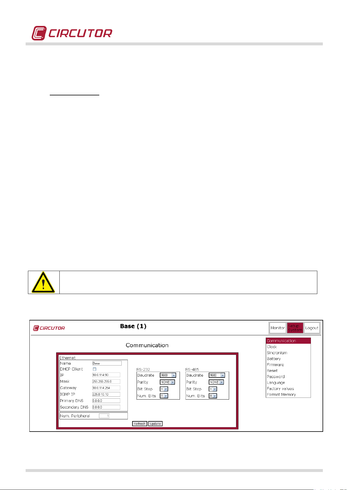
POWER QUALITY ANALYZER QNA500 8IO
All modules will be automatically reset when any parameter of the
Setup System
This function displays the following options:
• Communications: shows the configuration of the 3 ports of the M-BASE m odule. The following
information is displayed for each port:
• Speed
• Parity
• Stop bits
• Number of bits
The following information of the ETHERNET port is displayed:
• Name of the module
• DHCP enabled/disabled
• IP Address
• Net mask
• Gateway
• IGMP IP (Internet Group Management Protocol) is a multicast IP. All MULTIFIT
modules must have the same IGMP. This is required for each module to recognise
other modules. In addition, this allows the creation of multicast groups.
• Device number
WARNING:
ETHERNET port configuration is changed.
In addition, this window has 2 buttons to refresh the information displayed.
QNA500 8IO Instruction manual
49 / 111
Page 50

POWER QUALITY ANALYZER QNA500 8IO
• Clock: this option allows to set time to the power quality analyzer. This time can be UTC t ime or
other.
• Synchronism: this option allows to synchronize time to M-BASE module to an NTP server. In
this way, it’s possible to be sure that power quality analyzer has always the correct time.
QNA500 8IO Instruction manual
50 / 111
Page 51

POWER QUALITY ANALYZER QNA500 8IO
• Battery: This option shows the battery disconnection time. This time can be adjusted from 1 to
15 minutes.
• Firmware: This option shows the firmware version of the M-BASE module. The WEB server can
display the current firmware version and allows the user to select a version file and send it to
the M-BASE module. Press the "update" button to confirm. The system will auto-detect any
firmware versions sent to incorrect modules and notify the error.
• Reset: This window will show a button that can be used to reset all modules connected to the
M-BASE module. User confirmation is requested when pressing this button, in order to prevent
user errors.
QNA500 8IO Instruction manual
51 / 111
Page 52

POWER QUALITY ANALYZER QNA500 8IO
• Password: This window can be used to configure a read and write password. These passwords
can only be configured by the master user. The user read and write permissions are common to
all modules associated with the M-BASE module.
• Language: This window can be used to select the language of the WEB server.
QNA500 8IO Instruction manual
52 / 111
Page 53

POWER QUALITY ANALYZER QNA500 8IO
• Factory values: This window can be used to retrieve the default setup parameters. This
instruction does not change anything related to communications (IP address, IGMP, etc) or
passwords.
• Format Memory: This option erase memory of M-BASE and all files.
Log-Out
This operation can perform a controlled session shutdown. When the WEB server is not shut down with
this procedure, the same user will not be able to log on to the WEBV server again until the inactivity
time has expired. At this moment, the WEB server will automatically close the session.
QNA500 8IO Instruction manual
53 / 111
Page 54

POWER QUALITY ANALYZER QNA500 8IO
10.3.- QNA500 Setup
A user and password must be entered to access the W EB server of the QNA500 module, as in the
case of the M-BASE module.
The default user names and password of the 2 types of user are as follows:
Master user and password: root & cir-root
Query User and Password: user & cir-user
The WEB server has a menu with the following functions:
QNA500 8IO Instruction manual
54 / 111
Page 55

POWER QUALITY ANALYZER QNA500 8IO
Monitor
• Measure: this option shows the instantaneous values of the main electrical variables.
• Energy: this option allows to see in real-time energy values (active, reactive L and reactive C).
• Power Quality: this option can monitor the instantaneous values of the THD V and THD I
variables in real time, including the voltage and current unbalances.
QNA500 8IO Instruction manual
55 / 111
Page 56

POWER QUALITY ANALYZER QNA500 8IO
• Files: this option displays all files recorded in the SD card of the QNA500 power quality
analyzer. The file creation date, name of the file and size (in bytes) are shown
• Modules: shows all connected modules. This function is automatically performed by all modules
of the MULTIFIT system. The main window shows the following information of each module:
• Peripheral number
• Name of the module
• Type of module
• IP Address
• MAC address
QNA500 8IO Instruction manual
56 / 111
Page 57

POWER QUALITY ANALYZER QNA500 8IO
Setup System
• Installation: this option shows the analyzer's configuration values. In addition, this window can
also be used to configure the registry values, such as the transformation ratios, nominal
voltages, nominal frequency and other quality parameters.
• Communications: this option can be selected to modify the ETHERNET communication
parameters of the QNA500 module. These parameters are different to those used by the M-
BASE module, since the analyzer operates as a different IP device.
QNA500 8IO Instruction manual
57 / 111
Page 58

POWER QUALITY ANALYZER QNA500 8IO
• Synchronization: this option allows you to synchronize the time of one or more modules using
NTP. You can program two NTP servers, with its own port and even make a communication test
using the 'Get Time'. In case you want the entire set has QNA500 the same time, activate the
option 'Enable Synchronization' shows the date and time of the analyzer.
The parameters to be set are as follows:
Server name: DNS server address time (you can introduce DNS or IP a ddress)
Get IP: returns the IP address of the DNS server introduced
IP: IP address of the NTP server
Port: Port of NTP server synchronization (usually port 123)
Get Time: test button allows the check introduced NTP server (if you receive the date
and time with value 0 means no communication).
QNA500 8IO Instruction manual
58 / 111
Page 59

POWER QUALITY ANALYZER QNA500 8IO
• Email: this option allows to configure e-mail account and e-mail directions to send alarms. This
e-mail option allows to configure up to 16 different addresses grouped into 4 groups.
Configure SMTP connection:
Server Name: is the address of the SMTP server you want. This field is not required, you can enter just
the IP.
IP is the IP address of the SMTP server of the company. This field is required. (if you use an external
email account you have to introduce the IP address of this email)
Port: The port is managed by the send/receive functionality (usually port 25)
Get IP: used to know the IP address of the SMTP server. Failure to know the IP address, you must
enter the DNS address and press the corresponding button for the IP.
User: person who sends email (email account)
Password: password of email sender
QNA500 8IO Instruction manual
59 / 111
Page 60

POWER QUALITY ANALYZER QNA500 8IO
ATTENTION: EMAIL account must not have SSL protocol. If this option is enable,
you must disable it to allow send emails of the power quality analyzer. Although
sending emails is done without SSL, mails are sent encrypted in a secure w ay.
The information contained in the email is:
Alarm status (On / Off)
Alarm description
Date and time of activation
Alarm code
Value
Range of alarm assessment (MAX / MIN)
Activation time
Deactivation Time
• Battery: this option displays the power supply time of the internal battery during which the
module can operate. This time must be shorter than that programmed in the M-BASE module,
which is shaded. Each module can have a different disconnection time.
• Firmware: this option displays the firmware version of the microprocessor of the QNA500 8IO
module and the firmware of the associated DSP.
QNA500 8IO Instruction manual
60 / 111
Page 61

POWER QUALITY ANALYZER QNA500 8IO
• Password: this option can configure a write and read password. These passwords are
independent of the M-BASE module.
• Language: this option can be used to select the language of the W EB server of the QNA500
8IO module.
• Factory values: This window can be used to retrieve the default setup parameters.
QNA500 8IO Instruction manual
61 / 111
Page 62

POWER QUALITY ANALYZER QNA500 8IO
Setup STD Register
• Registers period: this option can configure the recording period for all electrical variables and
energy variables in separate files.
• Main measure: t his option can select the electrical variables that will be recorded. A series of
variables are enabled by default, so we recommend checking these variables to make sure that
they are the ones required by the user.
QNA500 8IO Instruction manual
62 / 111
Page 63

POWER QUALITY ANALYZER QNA500 8IO
• Power Measure: this option allows selection of power variables that will be recorded. A series of
variables are enabled by default, so we recommend checking these variables to make sure that
they are the ones required by the user.
• Voltage Harmonics: this option can select the voltage harmonics that will be recorded. A series
of variables are enabled by default, so we r ecommend check ing these variables to make sure
that they are the ones required by the user.
QNA500 8IO Instruction manual
63 / 111
Page 64

POWER QUALITY ANALYZER QNA500 8IO
• Current Harmonics: this option c an select the current harmonics that will be recorded. A series
of variables are enabled by default, so we r ecommend check ing these variables to make sure
that they are the ones required by the user.
• Voltage Interharmonics: this option can select the voltage interharmonics that will be recorded.
These variables are not enabled by default, so we recommend checking these variables to
make sure that they are the ones required by the user.
QNA500 8IO Instruction manual
64 / 111
Page 65

POWER QUALITY ANALYZER QNA500 8IO
• Current Interharmonics: this option can select the current interharmonics that will be recorded.
These variables are not enabled by default, so we recommend checking these variables to
make sure that they are the ones required by the user.
• Memory format: this option allows format of all data stored in the memory, including all data
associated to events and disturbances recorded. Make sure that all information stored in the
system has been downloaded before selecting this option, since it can not be recovered after
this option has been selected.
QNA500 8IO Instruction manual
65 / 111
Page 66

POWER QUALITY ANALYZER QNA500 8IO
To ensure correct setup of transient capture, WEB Server shows variable ‘Disturb State’
Setup Waveform recording
• Transient detection: this option selects the sensitivity level established to detect and record
voltage or current transients. A greater or lower variation of the sine wave measured will be
required to activate the transient recording mode, depending on the value established.
which shows ‘Activate’ or ‘Deactivate’ status. If this state is act ivated after setup, this
shows that trigger sensibility is not correctly setup or that it is too much sensible, so it’s
recommendable to increase sensibility level. Otherwise, QNA500 will be registering
transients continuously.
• Waveform recording: this option selects the variables recorded in the transient file. The user can
select the voltage and current channels to activate this recording mode.
The option can be selected to record the following:
• Transient
• Voltage event
QNA500 8IO Instruction manual
66 / 111
Page 67

POWER QUALITY ANALYZER QNA500 8IO
Setup Object
• Alarm Object: This option allows to manage alarms (digital objects) through MULTIFIT system.
These messages can be sent to any module or QNA500. These variables refer to electrical
parameters measured by the analyzer QNA500. To check list of codes for each digital object,
consult the table in this manual. It can be selected for the alarm, maximum or minimum values
as well as a delay in the activation or deactivation. When alarm is enable, the alarm will be sent.
You can also register the alarm in the file. EVA. In parallel, QNA5 00 has a WEB-Mail server, so
user can enable the alarm to send an email address or group of addresses previously
configured. The text entered in description (16 characters) will be the added to the email, with
the values MAX / MIN of the alarm.
QNA500 8IO Instruction manual
67 / 111
Page 68

POWER QUALITY ANALYZER QNA500 8IO
• Energy Object: this option allows to manage message with energy values to a module 8iO. To
create energy pulses. Enabling this option user can have a pulse output of a module 8iO,
generating a pulse train proportional to the measured energy. This action can be performed with
the energies active / reactive both consumption and generation.
QNA500 8IO Instruction manual
68 / 111
Page 69

POWER QUALITY ANALYZER QNA500 8IO
• Energy Object List: this option allows to list energy object list.
• Digital Ob ject Register: this option allows to register any object (alarm) sent by other modules.
In that way it works as a stack of alarms. User can set up to 16 different alarms of any
MULTIFIT system module.
Log-Out
This operation can perform a controlled session shutdown. When the WEB server is not shut down with
this procedure, the same user will not be able to log on to the WEBV server again until the inactivity
time has expired. At this moment, the WEB server will automatically close the session.
QNA500 8IO Instruction manual
69 / 111
Page 70

POWER QUALITY ANALYZER QNA500 8IO
10.4.- M-8IO Setup
An user and a password must be entered to access the W EB server of the M-8IO module, as in the
case of the M-BASE module.
The default user names and password of the 2 types of user are as follows:
Master user and password: root & cir-root
Guest user and Password: user & cir-user
The WEB server has a menu with the following functions:
QNA500 8IO Instruction manual
70 / 111
Page 71

POWER QUALITY ANALYZER QNA500 8IO
Monitor
• Files: this option displays all files recorded in the SD card of the M-8IO analyzer. The file
creation date, name of the file and size (in bytes) are shown
• Modules: shows all connected modules. This function is automatically performed by all modules
of the MULTIFIT system. The main window shows the following information of each module:
• Peripheral number
• Name of the module
• Type of module
• IP Address
• MAC address
QNA500 8IO Instruction manual
71 / 111
Page 72

POWER QUALITY ANALYZER QNA500 8IO
• Pulse Counter: Displays the value of the energy pulses received at each digital input.
• Digital Objects: This option can be used to monitor the state of digital objects created. The
alarm or message states received by the M-8IO module can be monitored.
QNA500 8IO Instruction manual
72 / 111
Page 73

POWER QUALITY ANALYZER QNA500 8IO
• Digital Time Objects: This option show status of Time alarms, which can be activated or
deactivated.
.
Setup System
• Communications: t his option can modify the ETHERNET communication parameters of the M8IO module and the peripheral number or device name. These parameters are different from
those used by the M-BASE module, since the MULTIFIT module operates as a different IP
device. Make sure that the IGMP address is the same for all MULTIFIT modules, since this
address is used to establish the communications between the MULTIFIT modules.
QNA500 8IO Instruction manual
73 / 111
Page 74

POWER QUALITY ANALYZER QNA500 8IO
• Synchronization: this option allows synchronizing time in one or several MULTIFIL modules
using an NTP Server. It’s possible to setup 2 NTP server with its own IP address and port and
moreover to test if the communication is correct, using ‘Get Time’ button. If user want s that all
the modules works with the same date and time, option ‘Synchronization Enable’ must be
selected.
• Email: this option allows to configure e-mail account and e-mail directions to send alarms. This
e-mail option allows configuring up to 16 different addresses grouped into 4 groups.
QNA500 8IO Instruction manual
74 / 111
Page 75

POWER QUALITY ANALYZER QNA500 8IO
• Battery: this option displays the power supply time of the internal battery during which the
module can operate. This time must be shorter than that programmed in the M-BASE module,
which is shaded. Each module must have a different disconnection time.
•
• Firmware: this option displays the firmware version of the microprocessor of the M-8IO module
and the firmware of the associated DSP.
•
QNA500 8IO Instruction manual
75 / 111
Page 76

POWER QUALITY ANALYZER QNA500 8IO
• Password: this option can configure a write and read password. These passwords are
independent of the M-BASE module.
• Language: this option can be used to select the language of the WEB server of the M-8IO
module.
QNA500 8IO Instruction manual
76 / 111
Page 77

POWER QUALITY ANALYZER QNA500 8IO
• Factory values: This window can be used to retrieve the default setup parameters.
Setup Registers
• Register period: this option allows setup a register period to the pulses received in the 8 digital
inputs. M-8iO allows making a load profile register with pulses received by using its digital
inputs. This load profile is similar to the information registered by energy meters with memory of
data. This information is registered in a .STD file which is created each month. Register period
is 15 minutes by default, but it’s a configurable variable.
QNA500 8IO Instruction manual
77 / 111
Page 78

POWER QUALITY ANALYZER QNA500 8IO
• Format memory: t his option allows deleting all information reg istered in the memory (files .std
and .eva).
Setup Objects
• Hardware outputs: this option allows open/close remotely all relays manually.
o Automatic: all relays are open/close depending on alarms pre configured.
o Manual: all relays are open/close when user decides (remote control) or by using
MODBUS instructions executed by external PLC.
QNA500 8IO Instruction manual
78 / 111
Page 79

POWER QUALITY ANALYZER QNA500 8IO
• Pulse Counter: this option can count the pulses in each digital input and program a series of
additional variables:
o name or description, so that it is more intuitive for the user
o weight of the pulse (e.g., M-8IO can record a value of X for each pulse received)
o number of decimal places (from 0.1 to 0.0001)
• Digital Objects: this option allows configuration of up to 16 alarms (or digital objects). These
alarms can ref er t o th e ala rm s fr om a dif f er ent MULTIFIT device. (The following example shows
how to close relay output no. 1, depending on the pulse received on digital input no. 1 and send
this notification to a QNA500 8IO module with peripheral no. 22, with the use of the WEB
server).
Select the new digital object from the list (16 available)
Write a name (
for example Test alarm)
Enter the following value in the "Peripheral" text field: 0
Enter the following value in the "Digital Object" text field: 101
(Not required) you can enter up to 8 arithmetic conditions: OR AND, OR NOT,
AND NOT.
Select the "Logic" variable as: Positive
Select the “Hardware Output” variable as: 01
“Active” checkbox: Enabled
Select the "Active" checkbox on the "Send to" option: Enabled
Enter the following value in the "Peripheral" text field: 22
QNA500 8IO Instruction manual
79 / 111
Page 80

POWER QUALITY ANALYZER QNA500 8IO
• Digital Ob jects List: this option shows the list of alarms (or digital objects) created in t he M-8IO
module
• Energy Objects: this option allows configuration of up to 8 energy alarms (or energy objects). In
general, this option will be enabled when the user wishes to send an energy pulse through the
transistor's digital outputs, depending on the energy measurement of a QNA500 module. The
high power and flexibility of the M-8IO module can be used to configure the weight of the pulse
and the time during which the unit is on (T
(T
OFF). (The following example shows how to enable pulse out put no. 3 of an M-8IO module
QNA500 8IO Instruction manual
ON) and time during which the equipment is off
80 / 111
Page 81

POWER QUALITY ANALYZER QNA500 8IO
with peripheral number 23 to generate pulses proportional to the energy measured by a
QNA500 module with peripheral number 22 with the use of a WEB server).
First, create the energy object in QNA500
• Open the Configure Objects menu of the QNA500
• Activate Digital Object 1
• Active Checkbox: Enabled
• Type: Energy + (
• Description: Active energy (
• Send to: 23 (
three-phase active energy)
for example)
peripheral number of the M-8IO)
• Active: Enabled
• Press the Update button
Return to the WEB server of the M-8IO module.
• Select the new energy object from the list (
8 available): 1
• Peripheral: 22
• Energy object: 1 (
• Description: Active energy (
• Quantity: 1 (
previously configured in the QNA500 8IO)
for example)
this would generate 1 pulse every 1 W/h)
• Units: W
• T
ON: 10 (this time is multiplied x10ms, i.e., the minimum possible)
• T
OFF: 10 (this time is multiplied x10ms, i.e., the minimum possible)
• Hardware Output: 3 (
pulse output being activated)
• Active Checkbox: Enabled
QNA500 8IO Instruction manual
81 / 111
Page 82

POWER QUALITY ANALYZER QNA500 8IO
• Energy Objects List: this option shows the list of energy alarms (or digital energy objects)
created in the M-8IO module.
• Time Object: this option allows to configure opening and reclosing relays functions depending
on Time conditions. It’s posible to setup load connection and disconnection depending time
conditions.
QNA500 8IO Instruction manual
82 / 111
Page 83

POWER QUALITY ANALYZER QNA500 8IO
• Time Object List: t his option shows all time alarms configured in the 8iO module.
Log-Out
This operation can perform a controlled session shutdown. When the WEB server is not shut down with
this procedure, the same user will not be able to log on to the WEBV server again until the inactivity
time has expired. At this moment, the WEB server will automatically close the session.
QNA500 8IO Instruction manual
83 / 111
Page 84

POWER QUALITY ANALYZER QNA500 8IO
11.- COMMUNICATIONS PROTOCOLS
QNA500 has various communications protocols, as a result of its powerful internal management
system. It can send data to SCADA systems, market PLC systems or any indust rial system that uses
the following protocols. These protocols are available on the 3 communications ports of the M-BASE
module.
11.1.- MODBUS / RTU
QNA500 8IO uses the Modbus/RTU ® protocol as the main communications protocol. This is a query-
response based protocol. The query frame format is as follows:
NPAAXXXXYYYYCRC.
NP: Peripheral number configured in the system.
AA: Modbus function to be performed.
XXXX: Memory position of the unit where the function will be started. (For ex., when AA=04 is
the read function).
YYYY: Read positions that are read or written from the XXXX position (depending on the AA
function).
CRC: 16-bit error detection code. (generated automatically).
The response format will be as follows:
NPAABBCCCC.. CRC
NP: Peripheral number responding to the query.
AA: Function responding to the query.
BB: Number of bytes of the response.
CCCC: Value that contains the record
...
CRC: Error detection registry.
Refer to the standard Modbus ® protocol for more information.
The Modbus memory map is attached to the communications appendix.
The following port must be used when establishing communications through the Ethernet port: 20003
QNA500 8IO Instruction manual
84 / 111
Page 85

POWER QUALITY ANALYZER QNA500 8IO
MODBUS VARIABLES
INSTANTANEOU
S
PHASE 1
Voltage selected (Vpn or
Vpp (only in case 3w mode
selection)
Current
A1
02 - 03
104 - 107
304 - 307
A x 1000
Active power
kW1
04 - 05
108 - 10B
308 - 30B
W
Inductive reactive power
kvarL1
06 - 07
10C - 10F
30C - 30F
Var
Capacitive reactive power
kvarC1
08 - 09
110 - 113
310 - 313
Var
Apparent power
kVA1
0A - 0B
114 - 117
314 - 317
VA
Power factor
PF1
0C - 0D
118 - 11B
318 - 31B
x100
Cosϕ
Cosϕ1
0E - 0F
11C - 11F
31C - 31F
x100
PHASE 2
Voltage selected (Vpn or
Vpp)
Vpp (only in case 3w mode
Current
A2
12 - 13
124 - 127
324 - 327
A x 1000
Active power
kW2
14 - 15
128 - 12B
328 - 32B
W
Inductive reactive power
kvarL2
16 - 17
12C - 12F
32C - 32F
Var
Capacitive reactive power
kvarC2
18 - 19
130 - 133
330 - 333
var
Apparent power
kVA2
1A - 1B
134 - 137
334 - 337
VA
Power factor
PF2
1C - 1D
138 - 13B
338 - 33B
x100
Cosϕ
Cosϕ2
1E - 1F
13C - 13F
33C - 33F
x100
PHASE 3
Voltage selected (Vpn or
Vpp (only in case 3w mode
Current
A3
22 – 23
144 – 147
344 – 347
A x 1000
Active power
kW3
24 – 25
148 – 14B
348 – 34B
W
Inductive reactive power
kvarL3
26 – 27
14C – 14F
34C – 34F
Var
Capacitive reactive power
kvarC3
28 – 29
150 – 153
350 – 353
var
Apparent power
kVA3
2ª – 2B
154 – 157
354 – 357
VA
Power factor
PF3
2C – 2D
158 – 15B
358 – 35B
x100
Cosϕ
Cosϕ3
2E – 2F
15C – 15F
35C – 35F
x100
NEUTRAL
Neutral voltage
Un
30 – 31
160 – 163
360 – 363
V x 100
Neutral current
In
32 – 33
164 – 167
364 – 367
A x 1000
Frequency (L1)
Hz
34 – 35
168 – 169
368 – 369
Hz x 100
THREE-PHASE
Three-phase phase voltage
Vn_III
40 – 41
180 – 183
380 – 383
V x 100
Three-phase current
I_III
42 – 43
184 – 187
384 – 387
A x 1000
Active three-phase power
kWIII
44 – 45
188 – 18B
388 – 38B
W
Inductive three-phase power
kvarLIII
46 – 47
18C – 18F
38C – 38F
Var
Capacitive three-phase
power
Apparent three-phase power
kVAIII
4ª – 4B
194 – 197
394 – 397
VA
Three-phase power factor
PFIII
4C – 4D
198 – 19B
398 – 39B
x100
Three-phase cos ϕ
CosφIII
4E – 4F
19C – 19F
39C – 39F
x100
11.1.1.- MODBUS/RTU MEMORY ADDRESS LIST OF THE QNA500
This address map can be modified so it is strongly recommended to download updated information
from CIRCUTOR’s webpage.
Instantaneous variables
VARIABLE SYMBOL
Vpp)
selection)
V1 00 - 01 100 - 103 300 - 303 V x 100
V12 3A - 3B 174 - 177 374 - 377 V x 100
V2 10 - 11 120 - 123 320 - 323 V x 100
V23 3C - 3D 178 - 17B 378 - 37B V x 100
MAXIMUM MINIMUM UNITS
Vpp)
selection)
V3 20 – 21 140 – 143 340 – 343 V x 100
V31 3E - 3F 17C - 17F 37C - 37F V x 100
kvarCIII 48 – 49 190 – 193 390 – 393 Var
QNA500 8IO Instruction manual
85 / 111
Page 86

POWER QUALITY ANALYZER QNA500 8IO
MODBUS VARIABLES
VARIABLE
SYMBOL
INSTANTANEOU
MAXIMUM
MINIMUM
UNITS
THD
THD U1
THDU1
50 – 51
1ª0 – 1ª3
3ª0 – 3ª3
%x10
THD U 2
THDU2
52 – 53
1ª4 – 1ª7
3ª4 – 3ª7
%x10
THD U 3
THDU3
54 – 55
1ª8 – 1AB
3ª8 – 3AB
%x10
THD UN
THDUN
56 – 57
1AC – 1AF
3AC – 3AF
%x10
THD I 1
THDI1
58 – 59
1B0 – 1B3
3B0 – 3B3
%x10
THD I 2
THDI2
5A – 5B
1B4 – 1B7
3B4 – 3B7
%x10
THD I 3
THDI3
5C – 5D
1B8 – 1BB
3B8 – 3BB
%x10
THD IN
THDIN
5E – 5F
1BC – 1BF
3BC – 3BF
%x10
Unbalance
U Unbalance
Kd U
60 – 61
1C0 – 1C3
3C0 – 3C3
%x10
U Asymmetry
Ka U
62 – 63
1C4 – 1C7
3C4 – 3C7
%x10
I Unbalance
Kd I
64 – 65
1C8 – 1CB
3C8 – 3CB
%x10
I Asymmetry
Ka I
66 – 67
1CC – 1CF
3CC – 3CF
%x10
FLICKER
PST V1 Statistical Flicker
PST_V1
68 – 69
x10
PST V2 Statistical Flicker
PST_V2
6A – 6B
x10
PST V3 Statistical Flicker
PST_V3
6C – 6D
x10
EARTH LEAKAGE
Id
Id
6E – 6F
1D0 – 1D3
3D0 – 3D3
MODBUS VARIABLES
VARIABLE
SYMBOL
Wh
mWh
Active energy
kWh III
500 - 501
502 - 503
Inductive reactive energy
kvarhL III
504 - 505
506 - 507
Capacitive reactive energy
kvarhC III
508 - 509
50A - 50B
Active energy generated
kWhIII (-)
50C - 50D
50E - 50F
Inductive energy generated
kvarLhIII (-)
510 - 511
512 - 513
Capacitive energy generated
kvarChIII (-)
514 - 515
516 - 517
S
CURRENT
Current energy variables
QNA500 8IO Instruction manual
86 / 111
Page 87

Harmonics variables
MODBUS VARIABLES
VARIABLE
SYMBOL
V1
V2
V3
Vn
UNITS
Base
U_fund
0A28 - 0A29
0A5C - 0A5D
0A90 - 0A91
0AC4 - 0AC5
U x 100
Harmonic 2
H2
0A2A
0A5E
0A92
0AC6
%x10
Harmonic 3
H3
0A2B
0A5F
0A93
0AC7
%x10
Harmonic 4
H4
0A2C
0A60
0A94
0AC8
%x10
Harmonic 5
H5
0A2D
0A61
0A95
0AC9
%x10
Harmonic 6
H6
0A2E
0A62
0A96
0ACA
%x10
Harmonic 7
H7
0A2F
0A63
0A97
0ACB
%x10
Harmonic 8
H8
0A30
0A64
0A98
0ACC
%x10
Harmonic 9
H9
0A31
0A65
0A99
0ACD
%x10
Harmonic 10
H10
0A32
0A66
0A9A
0ACE
%x10
Harmonic 11
H11
0A33
0A67
0A9B
0ACF
%x10
Harmonic 12
H12
0A34
0A68
0A9C
0AD0
%x10
Harmonic 13
H13
0A35
0A69
0A9D
0AD1
%x10
Harmonic 14
H14
0A36
0A6A
0A9E
0AD2
%x10
Harmonic 15
H15
0A37
0A6B
0A9F
0AD3
%x10
Harmonic 16
H16
0A38
0A6C
0AA0
0AD4
%x10
Harmonic 17
H17
0A39
0A6D
0AA1
0AD5
%x10
Harmonic 18
H18
0A3A
0A6E
0AA2
0AD6
%x10
Harmonic 19
H19
0A3B
0A6F
0AA3
0AD7
%x10
Harmonic 20
H20
0A3C
0A70
0AA4
0AD8
%x10
Harmonic 21
H21
0A3D
0A71
0AA5
0AD9
%x10
Harmonic 22
H22
0A3E
0A72
0AA6
0ADA
%x10
Harmonic 23
H23
0A3F
0A73
0AA7
0ADB
%x10
Harmonic 24
H24
0A40
0A74
0AA8
0ADC
%x10
Harmonic 25
H25
0A41
0A75
0AA9
0ADD
%x10
Harmonic 26
H26
0A42
0A76
0AAA
0ADE
%x10
Harmonic 27
H27
0A43
0A77
0AAB
0ADF
%x10
Harmonic 28
H28
0A44
0A78
0AAC
0AE0
%x10
Harmonic 29
H29
0A45
0A79
0AAD
0AE1
%x10
Harmonic 30
H30
0A46
0A7A
0AAE
0AE2
%x10
Harmonic 31
H31
0A47
0A7B
0AAF
0AE3
%x10
Harmonic 32
H32
0A48
0A7C
0AB0
0AE4
%x10
Harmonic 33
H33
0A49
0A7D
0AB1
0AE5
%x10
Harmonic 34
H34
0A4A
0A7E
0AB2
0AE6
%x10
Harmonic 35
H35
0A4B
0A7F
0AB3
0AE7
%x10
Harmonic 36
H36
0A4C
0A80
0AB4
0AE8
%x10
Harmonic 37
H37
0A4D
0A81
0AB5
0AE9
%x10
Harmonic 38
H38
0A4E
0A82
0AB6
0AEA
%x10
Harmonic 39
H39
0A4F
0A83
0AB7
0AEB
%x10
Harmonic 40
H40
0A50
0A84
0AB8
0AEC
%x10
Harmonic 41
H41
0A51
0A85
0AB9
0AED
%x10
Harmonic 42
H42
0A52
0A86
0ABA
0AEE
%x10
Harmonic 43
H43
0A53
0A87
0ABB
0AEF
%x10
Harmonic 44
H44
0A54
0A88
0ABC
0AF0
%x10
Harmonic 45
H45
0A55
0A89
0ABD
0AF1
%x10
Harmonic 46
H46
0A56
0A8A
0ABE
0AF2
%x10
Harmonic 47
H47
0A57
0A8B
0ABF
0AF3
%x10
Harmonic 48
H48
0A58
0A8C
0AC0
0AF4
%x10
Harmonic 49
H49
0A59
0A8D
0AC1
0AF5
%x10
Harmonic 50
H50
0A5A
0A8E
0AC2
0AF6
%x10
POWER QUALITY ANALYZER QNA500 8IO
QNA500 8IO Instruction manual
87 / 111
Page 88

POWER QUALITY ANALYZER QNA500 8IO
MODBUS VARIABLES
VARIABLE
SYMBOL
I1
I2
I3
In
UNITS
Base
I_fund
0B54 - 0B55
0B88 - 0B89
0BBC - 0BBD
0BF0 - 0BF1
A x 1000
Harmonic 2
H2
0B56
0B8A
0BBE
0BF2
%x10
Harmonic 3
H3
0B57
0B8B
0BBF
0BF3
%x10
Harmonic 4
H4
0B58
0B8C
0BC0
0BF4
%x10
Harmonic 5
H5
0B59
0B8D
0BC1
0BF5
%x10
Harmonic 6
H6
0B5A
0B8E
0BC2
0BF6
%x10
Harmonic 7
H7
0B5B
0B8F
0BC3
0BF7
%x10
Harmonic 8
H8
0B5C
0B90
0BC4
0BF8
%x10
Harmonic 9
H9
0B5D
0B91
0BC5
0BF9
%x10
Harmonic 10
H10
0B5E
0B92
0BC6
0BFA
%x10
Harmonic 11
H11
0B5F
0B93
0BC7
0BFB
%x10
Harmonic 12
H12
0B60
0B94
0BC8
0BFC
%x10
Harmonic 13
H13
0B61
0B95
0BC9
0BFD
%x10
Harmonic 14
H14
0B62
0B96
0BCA
0BFE
%x10
Harmonic 15
H15
0B63
0B97
0BCB
0BFF
%x10
Harmonic 16
H16
0B64
0B98
0BCC
0C00
%x10
Harmonic 17
H17
0B65
0B99
0BCD
0C01
%x10
Harmonic 18
H18
0B66
0B9A
0BCE
0C02
%x10
Harmonic 19
H19
0B67
0B9B
0BCF
0C03
%x10
Harmonic 20
H20
0B68
0B9C
0BD0
0C04
%x10
Harmonic 21
H21
0B69
0B9D
0BD1
0C05
%x10
Harmonic 22
H22
0B6A
0B9E
0BD2
0C06
%x10
Harmonic 23
H23
0B6B
0B9F
0BD3
0C07
%x10
Harmonic 24
H24
0B6C
0BA0
0BD4
0C08
%x10
Harmonic 25
H25
0B6D
0BA1
0BD5
0C09
%x10
Harmonic 26
H26
0B6E
0BA2
0BD6
0C0A
%x10
Harmonic 27
H27
0B6F
0BA3
0BD7
0C0B
%x10
Harmonic 28
H28
0B70
0BA4
0BD8
0C0C
%x10
Harmonic 29
H29
0B71
0BA5
0BD9
0C0D
%x10
Harmonic 30
H30
0B72
0BA6
0BDA
0C0E
%x10
Harmonic 31
H31
0B73
0BA7
0BDB
0C0F
%x10
Harmonic 32
H32
0B74
0BA8
0BDC
0C10
%x10
Harmonic 33
H33
0B75
0BA9
0BDD
0C11
%x10
Harmonic 34
H34
0B76
0BAA
0BDE
0C12
%x10
Harmonic 35
H35
0B77
0BAB
0BDF
0C13
%x10
Harmonic 36
H36
0B78
0BAC
0BE0
0C14
%x10
Harmonic 37
H37
0B79
0BAD
0BE1
0C15
%x10
Harmonic 38
H38
0B7A
0BAE
0BE2
0C16
%x10
Harmonic 39
H39
0B7B
0BAF
0BE3
0C17
%x10
Harmonic 40
H40
0B7C
0BB0
0BE4
0C18
%x10
Harmonic 41
H41
0B7D
0BB1
0BE5
0C19
%x10
Harmonic 42
H42
0B7E
0BB2
0BE6
0C1A
%x10
Harmonic 43
H43
0B7F
0BB3
0BE7
0C1B
%x10
Harmonic 44
H44
0B80
0BB4
0BE8
0C1C
%x10
Harmonic 45
H45
0B81
0BB5
0BE9
0C1D
%x10
Harmonic 46
H46
0B82
0BB6
0BEA
0C1E
%x10
Harmonic 47
H47
0B83
0BB7
0BEB
0C1F
%x10
Harmonic 48
H48
0B84
0BB8
0BEC
0C20
%x10
Harmonic 49
H49
0B85
0BB9
0BED
0C21
%x10
Harmonic 50
H50
0B86
0BBA
0BEE
0C22
%x10
QNA500 8IO Instruction manual
88 / 111
Page 89

MODBUS VARIABLES
VARIABLE
SYMBOL
V1
V2
V3
Vn
UNITS
Interharmonic 1
IH1
1194
11C6
11F8
122A
%x10
Interharmonic 2
IH2
1195
11C7
11F9
122B
%x10
Interharmonic 3
IH3
1196
11C8
11FA
122C
%x10
Interharmonic 4
IH4
1197
11C9
11FB
122D
%x10
Interharmonic 5
IH5
1198
11CA
11FC
122E
%x10
Interharmonic 6
IH6
1199
11CB
11FD
122F
%x10
Interharmonic 7
IH7
119A
11CC
11FE
1230
%x10
Interharmonic 8
IH8
119B
11CD
11FF
1231
%x10
Interharmonic 9
IH9
119C
11CE
1200
1232
%x10
Interharmonic 10
IH10
119D
11CF
1201
1233
%x10
Interharmonic 11
IH11
119E
11D0
1202
1234
%x10
Interharmonic 12
IH12
119F
11D1
1203
1235
%x10
Interharmonic 13
IH13
11A0
11D2
1204
1236
%x10
Interharmonic 14
IH14
11A1
11D3
1205
1237
%x10
Interharmonic 15
IH15
11A2
11D4
1206
1238
%x10
Interharmonic 16
IH16
11A3
11D5
1207
1239
%x10
Interharmonic 17
IH17
11A4
11D6
1208
123A
%x10
Interharmonic 18
IH18
11A5
11D7
1209
123B
%x10
Interharmonic 19
IH19
11A6
11D8
120A
123C
%x10
Interharmonic 20
IH20
11A7
11D9
120B
123D
%x10
Interharmonic 21
IH21
11A8
11DA
120C
123E
%x10
Interharmonic 22
IH22
11A9
11DB
120D
123F
%x10
Interharmonic 23
IH23
11AA
11DC
120E
1240
%x10
Interharmonic 24
IH24
11AB
11DD
120F
1241
%x10
Interharmonic 25
IH25
11AC
11DE
1210
1242
%x10
Interharmonic 26
IH26
11AD
11DF
1211
1243
%x10
Interharmonic 27
IH27
11AE
11E0
1212
1244
%x10
Interharmonic 28
IH28
11AF
11E1
1213
1245
%x10
Interharmonic 29
IH29
11B0
11E2
1214
1246
%x10
Interharmonic 30
IH30
11B1
11E3
1215
1247
%x10
Interharmonic 31
IH31
11B2
11E4
1216
1248
%x10
Interharmonic 32
IH32
11B3
11E5
1217
1249
%x10
Interharmonic 33
IH33
11B4
11E6
1218
124A
%x10
Interharmonic 34
IH34
11B5
11E7
1219
124B
%x10
Interharmonic 35
IH35
11B6
11E8
121A
124C
%x10
Interharmonic 36
IH36
11B7
11E9
121B
124D
%x10
Interharmonic 37
IH37
11B8
11EA
121C
124E
%x10
Interharmonic 38
IH38
11B9
11EB
121D
124F
%x10
Interharmonic 39
IH39
11BA
11EC
121E
1250
%x10
Interharmonic 40
IH40
11BB
11ED
121F
1251
%x10
Interharmonic 41
IH41
11BC
11EE
1220
1252
%x10
Interharmonic 42
IH42
11BD
11EF
1221
1253
%x10
Interharmonic 43
IH43
11BE
11F0
1222
1254
%x10
Interharmonic 44
IH44
11BF
11F1
1223
1255
%x10
Interharmonic 45
IH45
11C0
11F2
1224
1256
%x10
Interharmonic 46
IH46
11C1
11F3
1225
1257
%x10
Interharmonic 47
IH47
11C2
11F4
1226
1258
%x10
Interharmonic 48
IH48
11C3
11F5
1227
1259
%x10
Interharmonic 49
IH49
11C4
11F6
1228
125A
%x10
Interharmonic 50
IH50
11C5
11F7
1229
125B
%x10
Interharmonics variables
POWER QUALITY ANALYZER QNA500 8IO
QNA500 8IO Instruction manual
89 / 111
Page 90

POWER QUALITY ANALYZER QNA500 8IO
VARIABLES MODBUS CURRENT INTERHARMONICS
VARIABLE
SYMBOL
I1
I2
I3
In
UNITS
Interharmonic 1
IH1
125C
128E
12C0
12F2
A x 1000
Interharmonic 2
IH2
125D
128F
12C1
12F3
%x10
Interharmonic 3
IH3
125E
1290
12C2
12F4
%x10
Interharmonic 4
IH4
125F
1291
12C3
12F5
%x10
Interharmonic 5
IH5
1260
1292
12C4
12F6
%x10
Interharmonic 6
IH6
1261
1293
12C5
12F7
%x10
Interharmonic 7
IH7
1262
1294
12C6
12F8
%x10
Interharmonic 8
IH8
1263
1295
12C7
12F9
%x10
Interharmonic 9
IH9
1264
1296
12C8
12FA
%x10
Interharmonic 10
IH10
1265
1297
12C9
12FB
%x10
Interharmonic 11
IH11
1266
1298
12CA
12FC
%x10
Interharmonic 12
IH12
1267
1299
12CB
12FD
%x10
Interharmonic 13
IH13
1268
129A
12CC
12FE
%x10
Interharmonic 14
IH14
1269
129B
12CD
12FF
%x10
Interharmonic 15
IH15
126A
129C
12CE
1300
%x10
Interharmonic 16
IH16
126B
129D
12CF
1301
%x10
Interharmonic 17
IH17
126C
129E
12D0
1302
%x10
Interharmonic 18
IH18
126D
129F
12D1
1303
%x10
Interharmonic 19
IH19
126E
12A0
12D2
1304
%x10
Interharmonic 20
IH20
126F
12A1
12D3
1305
%x10
Interharmonic 21
IH21
1270
12A2
12D4
1306
%x10
Interharmonic 22
IH22
1271
12A3
12D5
1307
%x10
Interharmonic 23
IH23
1272
12A4
12D6
1308
%x10
Interharmonic 24
IH24
1273
12A5
12D7
1309
%x10
Interharmonic 25
IH25
1274
12A6
12D8
130A
%x10
Interharmonic 26
IH26
1275
12A7
12D9
130B
%x10
Interharmonic 27
IH27
1276
12A8
12DA
130C
%x10
Interharmonic 28
IH28
1277
12A9
12DB
130D
%x10
Interharmonic 29
IH29
1278
12AA
12DC
130E
%x10
Interharmonic 30
IH30
1279
12AB
12DD
130F
%x10
Interharmonic 31
IH31
127A
12AC
12DE
1310
%x10
Interharmonic 32
IH32
127B
12AD
12DF
1311
%x10
Interharmonic 33
IH33
127C
12AE
12E0
1312
%x10
Interharmonic 34
IH34
127D
12AF
12E1
1313
%x10
Interharmonic 35
IH35
127E
12B0
12E2
1314
%x10
Interharmonic 36
IH36
127F
12B1
12E3
1315
%x10
Interharmonic 37
IH37
1280
12B2
12E4
1316
%x10
Interharmonic 38
IH38
1281
12B3
12E5
1317
%x10
Interharmonic 39
IH39
1282
12B4
12E6
1318
%x10
Interharmonic 40
IH40
1283
12B5
12E7
1319
%x10
Interharmonic 41
IH41
1284
12B6
12E8
131A
%x10
Interharmonic 42
IH42
1285
12B7
12E9
131B
%x10
Interharmonic 43
IH43
1286
12B8
12EA
131C
%x10
Interharmonic 44
IH44
1287
12B9
12EB
131D
%x10
Interharmonic 45
IH45
1288
12BA
12EC
131E
%x10
Interharmonic 46
IH46
1289
12BB
12ED
131F
%x10
Interharmonic 47
IH47
128A
12BC
12EE
1320
%x10
Interharmonic 48
IH48
128B
12BD
12EF
1321
%x10
Interharmonic 49
IH49
128C
12BE
12F0
1322
%x10
Interharmonic 50
IH50
128D
12BF
12F1
1323
%x10
QNA500 8IO Instruction manual
90 / 111
Page 91

MODBUS VARIABLES
VARIABLE
SYMBOL
INST.
MÁX.
MÍN.
UNITS
Degree
V1-V2
1770 - 1771
-
-
Degrees * 100
V2-V3
1772 - 1773
-
-
Degrees * 100
V1-I1
1774 - 1775
-
-
Degrees * 100
V2-I2
1776 - 1777
-
-
Degrees * 100
V3-I3
1778 - 1779
-
-
Degrees * 100
EVENT COUNTER
Interruption in P1 and P2
177A
-
-
Interruption in P3 and Sag in
177B
-
-
Sags in P2 and P3
177C
-
- Overvoltage in P1 and P2
177D
-
- Overvoltage in P3
177E
-
-
TRANSIENT COUNTER
Transient counter
177F
Date/time of last transient
1798 – 179E
Modbus
10270 –
10361
10270 –10361
0..9 //10 day
profile
10362 –
10362 – 10452
0..9 //10 day
10460 – 10471
Day profile 1
24 x 8 bits
0..8 // 9 tariffs
10472 – 10483
Day profile 2
24 x 8 bits
0..8 // 9 tariffs
10484 – 10495
Day profile 3
24 x 8 bits
0..8 // 9 tariffs
10496 – 10507
Day profile 4
24 x 8 bits
0..8 // 9 tariffs
10508 – 10519
Day profile 5
24 x 8 bits
0..8 // 9 tariffs
10520 – 10531
Day profile 6
24 x 8 bits
0..8 // 9 tariffs
10532 – 10543
Day profile 7
24 x 8 bits
0..8 // 9 tariffs
10544 – 10555
Day profile 8
24 x 8 bits
0..8 // 9 tariffs
10556 – 10567
Day profile 9
24 x 8 bits
0..8 // 9 tariffs
10568 – 10579
Day profile 10
24 x 8 bits
0..8 // 9 tariffs
10580 H
Number of active tariffs
8 bits
1..9
10580 L
External synchronism
8 bits
0..1 // 0-no 1-yes
10581 – 10585
Digital object for each tariff
10 x 8 bits
0..15
P1
TARIFFS
POWER QUALITY ANALYZER QNA500 8IO
CONFiGURATION:
Address
10452
–10585
10580 10585
Address
Variable modified
Type
Day profile 0 .. 183 184 x 8 bits
Day profile 184 .. 365 182 x 8 bits
Allow data
profile
QNA500 8IO Instruction manual
91 / 111
Page 92

Variable
Addresses
Num. Registers
Function
Energy tariff 1 present
7168(1C00) – 7191 (1C17)
24
04
Energy tariff 2 present
7200(1C20) – 7223 (1C37)
24
04
Energy tariff 3 present
7232(1C40) – 7255(1C57)
24
04
Energy tariff 4 present
7264(1C60) – 7287(1C77)
24
04
Energy tariff 5 present
7296(1C80) – 7319(1C97)
24
04
Energy tariff 6 present
7328(1CA0) – 7351(1CB7)
24
04
Energy tariff 7 present
7360(1CC0) – 7383(1CD7)
24
04
Energy tariff 8 present
7397(1CE0) – 7415(1CF7)
24
04
Energy tariff 9 present
7424(1D00) – 7447(1D17)
24
04
Energy tariff 1 last month
7456(1D20) – 7479(1D37)
24
04
Energy tariff 2 last month
7488(1D40) – 7511(1D57)
24
04
Energy tariff 3 last month
7520(1D60) – 7543(1D77)
24
04
Energy tariff 4 last month
7552(1D80) – 7575(1D97)
24
04
Energy tariff 5 last month
7584(1DA0) – 7607(1DB7)
24
04
Energy tariff 6 last month
7616(1DC0) – 7639(1DD7)
24
04
Energy tariff 7 last month
7648(1DE0) – 7671(1DF7)
24
04
Energy tariff 8 last month
7680(1E00) – 7703(1E17)
24
04
Energy tariff 9 last month
7712(1E20) – 7735(1E37)
24
04
Total energy last month
7744(1E40) – 7767(1E57)
24
04
Energy tariff 1 last year
7776 (1E60) – 7799(1E77)
24
04
Energy tariff 2 last year
7808(1E80) – 7831(1E97)
24
04
Energy tariff 3 last year
7840(1EA0) – 7863(1EB7)
24
04
Energy tariff 4 last year
7872(1EC0) – 7895(1ED7)
24
04
Energy tariff 5 last year
7904(1EE0) – 7927(1EF7)
24
04
Energy tariff 6 last year
7936(1F00) – 7959(1F17)
24
04
Energy tariff 7 last year
7976(1F20) – 7991(1F37)
24
04
Energy tariff 8 last year
8000(1F40) – 8023(1F57)
24
04
Energy tariff 9 last year
8032(1F60) – 8055(1F77)
24
04
Total energy last year
8064(1F80) – 8087(1F97)
24
04
MONITORIZATION
POWER QUALITY ANALYZER QNA500 8IO
QNA500 8IO Instruction manual
92 / 111
Page 93

POWER QUALITY ANALYZER QNA500 8IO
MODBUS VARIABLES
MAXIMUM DEMAND VARIABLE
SYMBOL
CODE
AVERAGE
MAX
Units
TARIFF 1
Total active power
Pd_kWIII
300
800-801
900-903
W
Total apparent power
Pd_kVAIII
301
802-803
904-907
VA
Total average current
Pd_I_AVG
302
804-805
908-90B
A x 1000
Current phase 1
Pd_I1
303
806-807
90C-90F
A x 1000
Current phase 2
Pd_I2
304
808-809
910-913
A x 1000
Current phase 3
Pd_I3
305
80A-80B
914-917
A x 1000
TARIFF 2
Total active power
Pd_kWIII
306
80C-80D
918-91B
W
Total apparent power
Pd_kVAIII
307
80E-80F
91C-91F
VA
Total average current
Pd_I_AVG
308
810-811
920-923
A x 1000
Current phase 1
Pd_I1
309
812-813
924-927
A x 1000
Current phase 2
Pd_I2
310
814-815
928-92B
A x 1000
Current phase 3
Pd_I3
311
816-817
92C-92F
A x 1000
TARIFF 3
Total active power
Pd_kWIII
312
818-819
930-933
W
Total apparent power
Pd_kVAIII
313
81A-81B
934-937
VA
Total average current
Pd_I_AVG
314
81C-81D
938-93B
A x 1000
Current phase 1
Pd_I1
315
81E-81F
93C-93F
A x 1000
Current phase 2
Pd_I2
316
820-821
940-943
A x 1000
Current phase 3
Pd_I3
317
822-823
944-947
A x 1000
TARIFF 4
Total active power
Pd_kWIII
318
824-825
948-94B
W
Total apparent power
Pd_kVAIII
319
826-827
94C-94F
VA
Total average current
Pd_I_AVG
320
828-829
950-953
A x 1000
Current phase 1
Pd_I1
321
82A-82B
954-957
A x 1000
Current phase 2
Pd_I2
322
82C-82D
958-95B
A x 1000
Current phase 3
Pd_I3
323
82E-82F
95C-95F
A x 1000
TARIFF 5
Total active power
Pd_kWIII
324
830-831
960-963
W
Total apparent power
Pd_kVAIII
325
832-833
964-967
VA
Total average current
Pd_I_AVG
326
834-835
968-96B
A x 1000
Current phase 1
Pd_I1
327
836-837
96C-96F
A x 1000
Current phase 2
Pd_I2
328
838-839
970-973
A x 1000
Current phase 3
Pd_I3
329
83A-83B
974-977
A x 1000
TARIFF 6
Total active power
Pd_kWIII
330
83C-83D
978-97B
W
Total apparent power
Pd_kVAIII
331
83E-83F
97C-97F
VA
Total average current
Pd_I_AVG
332
840-841
980-983
A x 1000
Current phase 1
Pd_I1
333
842-843
984-987
A x 1000
Current phase 2
Pd_I2
334
844-845
988-98B
A x 1000
Current phase 3
Pd_I3
335
846-847
98C-98F
A x 1000
TARIFF 7
Total active power
Pd_kWIII
336
848-849
990-993
W
Total apparent power
Pd_kVAIII
337
84A-84B
994-997
VA
Total average current
Pd_I_AVG
338
84C-84D
998-99B
A x 1000
Current phase 1
Pd_I1
339
84E-84F
99C-99F
A x 1000
Current phase 2
Pd_I2
340
850-851
9A0-9A3
A x 1000
Current phase 3
Pd_I3
341
852-853
9A4-9A7
A x 1000
TARIFF 8
Total active power
Pd_kWIII
342
854-855
9A8-9AB
W
Total apparent power
Pd_kVAIII
343
856-857
9AC-9AF
VA
Total average current
Pd_I_AVG
344
858-859
9B0-9B3
A x 1000
Current phase 1
Pd_I1
345
85A-85B
9B4-9B7
A x 1000
Current phase 2
Pd_I2
346
85C-85D
9B8-9BB
A x 1000
QNA500 8IO Instruction manual
93 / 111
Page 94

Current phase 3
Pd_I3
347
85E-85F
9BC-9BF
A x 1000
TARIFF 9
Total active power
Pd_kWIII
348
860-861
9C0-9C3
W
Total apparent power
Pd_kVAIII
349
862-863
9C4-9C7
VA
Total average current
Pd_I_AVG
350
864-865
9C8-9CB
A x 1000
Current phase 1
Pd_I1
351
866-867
9CC-9CF
A x 1000
Current phase 2
Pd_I2
352
868-869
9D0-9D3
A x 1000
Current phase 3
Pd_I3
353
86A-86B
9D4-9D7
A x 1000
MODBUS VARIABLES
VARIABLE
SYMBOL
kWh
Wh
TARIFF 1
Active energy
Kwh III
1C00-1C01
1C02-1C03
Inductive energy
KvarhL III
1C04-1C05
1C06-1C07
Capacitive energy
KvarhC III
1C08-1C09
1C0A-1C0B
Active energy generada
kWhIII (-)
1C0C-1C0D
1C0E-1C0F
Inductive energy Generated
kvarLhIII (-)
1C10-1C11
1C12-1C13
Capacitive energy Generated
kvarChIII (-)
1C14-1C15
1C16-1C17
TARIFF 2
Active energy
Kwh III
1C20-1C21
1C22-1C23
Inductive energy
KvarhL III
1C24-1C25
1C26-1C27
Capacitive energy
KvarhC III
1C28-1C29
1C2A-1C2B
Active energy generada
kWhIII (-)
1C2C-1C2D
1C2E-1C2F
Inductive energy Generated
kvarLhIII (-)
1C30-1C31
1C32-1C33
Capacitive energy Generated
kvarChIII (-)
1C34-1C35
1C36-1C37
TARIFF 3
Active energy
Kwh III
1C40-1C41
1C42-1C43
Inductive energy
KvarhL III
1C44-1C45
1C46-1C47
Capacitive energy
KvarhC III
1C48-1C49
1C4A-1C4B
Active energy generada
kWhIII (-)
1C4C-1C4D
1C4E-1C4F
Inductive energy Generated
kvarLhIII (-)
1C50-1C51
1C52-1C53
Capacitive energy Generated
kvarChIII (-)
1C54-1C55
1C56-1C57
TARIFF 4
Active energy
Kwh III
1C60-1C61
1C62-1C63
Inductive energy
KvarhL III
1C64-1C65
1C66-1C67
Capacitive energy
KvarhC III
1C68-1C69
1C6A-1C6B
Active energy generada
kWhIII (-)
1C6C-1C6D
1C6E-1C6F
Inductive energy Generated
kvarLhIII (-)
1C70-1C71
1C72-1C73
Capacitive energy Generated
kvarChIII (-)
1C74-1C75
1C76-1C77
TARIFF 5
Active energy
Kwh III
1C80-1C81
1C82-1C83
Inductive energy
KvarhL III
1C84-1C85
1C86-1C87
Capacitive energy
KvarhC III
1C88-1C89
1C8A-1C8B
Active energy generada
kWhIII (-)
1C8C-1C8D
1C8E-1C8F
Inductive energy Generated
kvarLhIII (-)
1C90-1C91
1C92-1C93
Capacitive energy Generated
kvarChIII (-)
1C94-1C95
1C96-1C97
TARIFF 6
Active energy
Kwh III
1CA0-1CA1
1CA2-1CA3
Inductive energy
KvarhL III
1CA4-1CA5
1CA6-1CA7
Capacitive energy
KvarhC III
1CA8-1CA9
1CAA-1CAB
Active energy generada
kWhIII (-)
1CAC-1CAD
1CAE-1CAF
MONITORING VARIABLES FOR PRESENT ENERGY
POWER QUALITY ANALYZER QNA500 8IO
QNA500 8IO Instruction manual
94 / 111
Page 95

POWER QUALITY ANALYZER QNA500 8IO
Inductive energy Generated
kvarLhIII (-)
1CB0-1CB1
1CB2-1CB3
Capacitive energy Generated
kvarChIII (-)
1CB4-1CB5
1CB6-1CB7
TARIFF 7
Active energy
Kwh III
1CC0-1CC1
1CC2-1CC3
Inductive energy
KvarhL III
1CC4-1CC5
1CC6-1CC7
Capacitive energy
KvarhC III
1CC8-1CC9
1CCA-1CCB
Active energy generada
kWhIII (-)
1CCC-1CCD
1CCE-1CCF
Inductive energy Generated
kvarLhIII (-)
1CD0-1CD1
1CD2-1CD3
Capacitive energy Generated
kvarChIII (-)
1CD4-1CD5
1CD6-1CD7
TARIFF 8
Active energy
Kwh III
1CE0-1CE1
1CE2-1CE3
Inductive energy
KvarhL III
1CE4-1CE5
1CE6-1CE7
Capacitive energy
KvarhC III
1CE8-1CE9
1CEA-1CEB
Active energy generada
kWhIII (-)
1CEC-1CED
1CEE-1CEF
Inductive energy Generated
kvarLhIII (-)
1CF0-1CF1
1CF2-1CF3
Capacitive energy Generated
kvarChIII (-)
1CF4-1CF5
1CF6-1CF7
TARIFF 9
Active energy
Kwh III
1D00-1D01
1D02-1D03
Inductive energy
KvarhL III
1D04-1D05
1D06-1D07
Capacitive energy
KvarhC III
1D08-1D09
1D0A-1D0B
Active energy generada
kWhIII (-)
1D0C-1D0D
1D0E-1D0F
Inductive energy Generated
kvarLhIII (-)
1D10-1D11
1D12-1D13
Capacitive energy Generated
kvarChIII (-)
1D14-1D15
1D16-1D17
QNA500 8IO Instruction manual
95 / 111
Page 96

MODBUS VARIABLES
VARIABLE
SYMBOL
kWh
Wh
TARIFF 1
Active energy
Kwh III
1D20-1D21
1D22-1D23
Inductive energy
KvarhL III
1D24-1D25
1D26-1D27
Capacitive energy
KvarhC III
1D28-1D29
1D2A-1D2B
Active energy generada
kWhIII (-)
1D2C-1D2D
1D2E-1D2F
Inductive energy Generated
kvarLhIII (-)
1D30-1D31
1D32-1D33
Capacitive energy Generated
kvarChIII (-)
1D34-1D35
1D36-1D37
TARIFF 2
Active energy
Kwh III
1D40-1D41
1D42-1D43
Inductive energy
KvarhL III
1D44-1D45
1D46-1D47
Capacitive energy
KvarhC III
1D48-1D49
1D4A-1D4B
Active energy generada
kWhIII (-)
1D4C-1D4D
1D4E-1D4F
Inductive energy Generated
kvarLhIII (-)
1D50-1D51
1D52-1D53
Capacitive energy Generated
kvarChIII (-)
1D54-1D55
1D56-1D57
TARIFF 3
Active energy
Kwh III
1D60-1D61
1D62-1D63
Inductive energy
KvarhL III
1D64-1D65
1D66-1D67
Capacitive energy
KvarhC III
1D68-1D69
1D6A-1D6B
Active energy generada
kWhIII (-)
1D6C-1D6D
1D6E-1D6F
Inductive energy Generated
kvarLhIII (-)
1D70-1D71
1D72-1D73
Capacitive energy Generated
kvarChIII (-)
1D74-1D75
1D76-1D77
TARIFF 4
Active energy
Kwh III
1D80-1D81
1D82-1D83
Inductive energy
KvarhL III
1D84-1D85
1D86-1D87
Capacitive energy
KvarhC III
1D88-1D89
1D8A-1D8B
Active energy generada
kWhIII (-)
1D8C-1D8D
1D8E-1D8F
Inductive energy Generated
kvarLhIII (-)
1D90-1D91
1D92-1D93
Capacitive energy Generated
kvarChIII (-)
1D94-1D95
1D96-1D97
TARIFF 5
Active energy
Kwh III
1DA0-1DA1
1DA2-1DA3
Inductive energy
KvarhL III
1DA4-1DA5
1DA6-1DA7
Capacitive energy
KvarhC III
1DA8-1DA9
1DAA-1DAB
Active energy generada
kWhIII (-)
1DAC-1DAD
1DAE-1DAF
Inductive energy Generated
kvarLhIII (-)
1DB0-1DB1
1DB2-1DB3
Capacitive energy Generated
kvarChIII (-)
1DB4-1DB5
1DB6-1DB7
TARIFF 6
Active energy
Kwh III
1DC0-1DC1
1DC2-1DC3
Inductive energy
KvarhL III
1DC4-1DC5
1DC6-1DC7
Capacitive energy
KvarhC III
1DC8-1DC9
1DCA-1DCB
Active energy generada
kWhIII (-)
1DCC-1DCD
1DCE-1DCF
Inductive energy Generated
kvarLhIII (-)
1DD0-1DD1
1DD2-1DD3
Capacitive energy Generated
kvarChIII (-)
1DD4-1DD5
1DD6-1DD7
TARIFF 7
Active energy
Kwh III
1DE0-1DE1
1DE2-1DE3
Inductive energy
KvarhL III
1DE4-1DE5
1DE6-1DE7
Capacitive energy
KvarhC III
1DE8-1DE9
1DEA-1DEB
Active energy generada
kWhIII (-)
1DEC-1DED
1DEE-1DEF
MONITORING VARIABLES LAST MONTH
POWER QUALITY ANALYZER QNA500 8IO
QNA500 8IO Instruction manual
96 / 111
Page 97

POWER QUALITY ANALYZER QNA500 8IO
Inductive energy Generated
kvarLhIII (-)
1DF0-1DF1
1DF2-1DF3
Capacitive energy Generated
kvarChIII (-)
1DF4-1DF5
1DF6-1DF7
TARIFF 8
Active energy
Kwh III
1E00-1E01
1E02-1E03
Inductive energy
KvarhL III
1E04-1E05
1E06-1E07
Capacitive energy
KvarhC III
1E08-1E09
1E0A-1E0B
Active energy generada
kWhIII (-)
1E0C-1E0D
1E0E-1E0F
Inductive energy Generated
kvarLhIII (-)
1E10-1E11
1E12-1E13
Capacitive energy Generated
kvarChIII (-)
1E14-1E15
1E16-1E17
TARIFF 9
Active energy
Kwh III
1E20-1E21
1E22-1E23
Inductive energy
KvarhL III
1E24-1E25
1E26-1E27
Capacitive energy
KvarhC III
1E28-1E29
1E2A-1E2B
Active energy generada
kWhIII (-)
1E2C-1E2D
1E2E-1E2F
Inductive energy Generated
kvarLhIII (-)
1E30-1E31
1E32-1E33
Capacitive energy Generated
kvarChIII (-)
1E34-1E35
1E36-1E37
TOTAL ENERGY LAST MONTH
Active energy
Kwh III
1E40-1E41
1E42-1E43
Inductive energy
KvarhL III
1E44-1E45
1E46-1E47
Capacitive energy
KvarhC III
1E48-1E49
1E4A-1E4B
Active energy generada
kWhIII (-)
1E4C-1E4D
1E4E-1E4F
Inductive energy Generated
kvarLhIII (-)
1E50-1E51
1E52-1E53
Capacitive energy Generated
kvarChIII (-)
1E54-1E55
1E56-1E57
MODBUS VARIABLES
VARIABLE
SYMBOL
kWh
Wh
TARIFF 1
Active energy
Kwh III
1E60-1E61
1E62-1E63
Inductive energy
KvarhL III
1E64-1E65
1E66-1E67
Capacitive energy
KvarhC III
1E68-1E69
1E6A-1E6B
Active energy generada
kWhIII (-)
1E6C-1E6D
1E6E-1E6F
Inductive energy Generated
kvarLhIII (-)
1E70-1E71
1E72-1E73
Capacitive energy Generated
kvarChIII (-)
1E74-1E75
1E76-1E77
TARIFF 2
Active energy
Kwh III
1E80-1E81
1E82-1E83
Inductive energy
KvarhL III
1E84-1E85
1E86-1E87
Capacitive energy
KvarhC III
1E88-1E89
1E8A-1E8B
Active energy generada
kWhIII (-)
1E8C-1E8D
1E8E-1E8F
Inductive energy Generated
kvarLhIII (-)
1E90-1E91
1E92-1E93
Capacitive energy Generated
kvarChIII (-)
1E94-1E95
1E96-1E97
TARIFF 3
Active energy
Kwh III
1EA0-1EA1
1EA2-1EA3
Inductive energy
KvarhL III
1EA4-1EA5
1EA6-1EA7
Capacitive energy
KvarhC III
1EA8-1EA9
1EAA-1EAB
Active energy generada
kWhIII (-)
1EAC-1EAD
1EAE-1EAF
Inductive energy Generated
kvarLhIII (-)
1EB0-1EB1
1EB2-1EB3
Capacitive energy Generated
kvarChIII (-)
1EB4-1EB5
1EB6-1EB7
TARIFF 4
Active energy
Kwh III
1EC0-1EC1
1EC2-1EC3
MONITORING VARIABLES LAST YEAR
QNA500 8IO Instruction manual
97 / 111
Page 98

POWER QUALITY ANALYZER QNA500 8IO
Inductive energy
KvarhL III
1EC4-1EC5
1EC6-1EC7
Capacitive energy
KvarhC III
1EC8-1EC9
1ECA-1ECB
Active energy generada
kWhIII (-)
1ECC-1ECD
1ECE-1ECF
Inductive energy Generated
kvarLhIII (-)
1ED0-1ED1
1ED2-1ED3
Capacitive energy Generated
kvarChIII (-)
1ED4-1ED5
1ED6-1ED7
TARIFF 5
Active energy
Kwh III
1EE0-1EE1
1EE2-1EE3
Inductive energy
KvarhL III
1EE4-1EE5
1EE6-1EE7
Capacitive energy
KvarhC III
1EE8-1EE9
1EEA-1EEB
Active energy generada
kWhIII (-)
1EEC-1EED
1EEE-1EEF
Inductive energy Generated
kvarLhIII (-)
1EF0-1EF1
1EF2-1EF3
Capacitive energy Generated
kvarChIII (-)
1EF4-1EF5
1EF6-1EF7
TARIFF 6
Active energy
Kwh III
1F00-1F01
1F02-1F03
Inductive energy
KvarhL III
1F04-1F05
1F06-1F07
Capacitive energy
KvarhC III
1F08-1F09
1F0A-1F0B
Active energy generada
kWhIII (-)
1F0C-1F0D
1F0E-1F0F
Inductive energy Generated
kvarLhIII (-)
1F10-1F11
1F12-1F13
Capacitive energy Generated
kvarChIII (-)
1F14-1F15
1F16-1F17
TARIFF 7
Active energy
Kwh III
1F20-1F21
1F22-1F23
Inductive energy
KvarhL III
1F24-1F25
1F26-1F27
Capacitive energy
KvarhC III
1F28-1F29
1F2A-1F2B
Active energy generada
kWhIII (-)
1F2C-1F2D
1F2E-1F2F
Inductive energy Generated
kvarLhIII (-)
1F30-1F31
1F32-1F33
Capacitive energy Generated
kvarChIII (-)
1F34-1F35
1F36-1F37
TARIFF 8
Active energy
Kwh III
1F40-1F41
1F42-1F43
Inductive energy
KvarhL III
1F44-1F45
1F46-1F47
Capacitive energy
KvarhC III
1F48-1F49
1F4A-1F4B
Active energy generada
kWhIII (-)
1F4C-1F4D
1F4E-1F4F
Inductive energy Generated
kvarLhIII (-)
1F50-1F51
1F52-1F53
Capacitive energy Generated
kvarChIII (-)
1F54-1F55
1F56-1F57
TARIFF 9
Active energy
Kwh III
1F60-1F61
1F62-1F63
Inductive energy
KvarhL III
1F64-1F65
1F66-1F67
Capacitive energy
KvarhC III
1F68-1F69
1F6A-1F6B
Active energy generada
kWhIII (-)
1F6C-1F6D
1F6E-1F6F
Inductive energy Generated
kvarLhIII (-)
1F70-1F71
1F72-1F73
Capacitive energy Generated
kvarChIII (-)
1F74-1F75
1F76-1F77
TOTAL ENERGY LAST YEAR
Active energy
Kwh III
1F80-1F81
1F82-1F83
Inductive energy
KvarhL III
1F84-1F85
1F86-1F87
Capacitive energy
KvarhC III
1F88-1F89
1F8A-1F8B
Active energy generada
kWhIII (-)
1F8C-1F8D
1F8E-1F8F
Inductive energy Generated
kvarLhIII (-)
1F90-1F91
1F92-1F93
Capacitive energy Generated
kvarChIII (-)
1F94-1F95
1F96-1F97
QNA500 8IO Instruction manual
98 / 111
Page 99

POWER QUALITY ANALYZER QNA500 8IO
Variable
Addresses
Num. Reg.
Function
Pulse counter input1
21000 (5208) – 21003 (520B)
4
04
Pulse weight input1
21004 (520C)
1
04/10
Num. dec imals Input1
21005 (520D)
1(first byte)
04/10
Enable Input1 as pulse counter
21005 (520D)
1(second byte)
04/10
Pulse description Input1
21006 (520E)
8
04/10
Pulse counter input2
21100 (526C) – 21103 (526F)
4
04
Pulse weight input2
21104 (5270)
1
04/10
Num. dec imals Input2
21105 (5271)
1(first byte)
04/10
Enable Input2 as pulse counter
21105 (5271)
1(second byte)
04/10
Pulse description Input2
21106 (5272)
8
04/10
Pulse counter input3
21200 (52D0) – 21203 (52D3)
4
04
Pulse weight input3
21204 (52D4)
1
04/10
Num. dec imals Input3
21205 (52D5)
1(first byte)
04/10
Enable Input3 as pulse counter
21205 (52D5)
1(second byte)
04/10
Pulse description Input3
21206 (52D6)
8
04/10
Pulse counter input4
21300 (5334) – 21303 (5337)
4
04
Pulse weight input4
21304 (5338)
1
04/10
Num. dec imals Input4
21305 (5339)
1(first byte)
04/10
Enable Input4 as pulse counter
21305 (5339)
1(second byte)
04/10
Pulse description Input4
21306 (533A)
8
04/10
Pulse counter input5
21400 (5398) – 21403 (539B)
4
04
Pulse weight input5
21404 (539C)
1
04/10
Num. dec imals Input5
21405 (539D)
1(first byte)
04/10
Enable Input5 as pulse counter
21405 (539D)
1(second byte)
04/10
Pulse description Input5
21406 (539E)
8
04/10
Pulse counter input6
21500 (53FC) – 21503 (53FF)
4
04
Pulse weight input6
21504 (5400)
1
04/10
Num. dec imals Input6
21505 (5401)
1(first byte)
04/10
Enable Input6 as pulse counter
21505 (5401)
1(second byte)
04/10
Pulse description Input6
21506 (5402)
8
04/10
Pulse counter input7
21600 (5460) – 21603 (5463)
4
04
Pulse weight input7
21604 (5464)
1
04/10
Num. dec imals Input7
21605 (5465)
1(first byte)
04/10
Enable Input7 as pulse counter
21605 (5465)
1(second byte)
04/10
Pulse description Input7
21606 (5466)
8
04/10
Pulse counter input8
21700 (54C4) – 21703 (54C7)
4
04
Pulse weight input8
21704 (54C8)
1
04/10
Num. dec imals Input8
21705 (54C9)
1(first byte)
04/10
Enable Input8 as pulse counter
21705 (54C9)
1(second byte)
04/10
Pulse description Input8
21706 (54CA)
8
04/10
Wirte outputs
24500 (5FB4)
1
10
Read inputs
24510 (5FBE)
1
04
11.1.2.- MODBUS/RTU MEMORY ADDRESS LIST OF THE M-8IO MODULE
QNA500 8IO Instruction manual
99 / 111
Page 100

POWER QUALITY ANALYZER QNA500 8IO
Variable
Addresses
Num. Reg.
Function
Read outputs
24550 (5FE6)
1
04
Enable force outputs
24560 (5FF0)
1
04/10
Status Input1
24570 (5FFA)
1
04
Status Input2
24571 (5FFB)
1
04
Status Input3
24572 (5FFC)
1
04
Status Input4
24573 (5FFD)
1
04
Status Input5
24574 (5FFE)
1
04
Status Input6
24575 (5FFF)
1
04
Status Input7
24576 (6000)
1
04
Status Input8
24577 (6001)
1
04
Status Output1
24580 (6004)
1
04/10
Status Output2
24581 (6005)
1
04/10
Status Output3
24582 (6006)
1
04/10
Status Output4
24583 (6007)
1
04/10
Status Output5
24584 (6008)
1
04/10
Status Output6
24585 (6009)
1
04/10
Status Output7
24586 (600A)
1
04/10
Status Output8
24587 (600B)
1
04/10
Enable manually Output1
24590 (600E)
1
04/10
Enable manually Output2
24591 (600F)
1
04/10
Enable manually Output3
24592 (6010)
1
04/10
Enable manually Output4
24593 (6011)
1
04/10
Enable manually Output5
24594 (6012)
1
04/10
Enable manually Output6
24595 (6013)
1
04/10
Enable manually Output7
24596 (6014)
1
04/10
Enable manually Output8
24597 (6015)
1
04/10
11.2.- MODBUS/TCP
This protocol is a variation of the MODBUS/RTU protocol that has been specially designed to work with
TCP/IP networks. The queries from various devices can be optionally accumulated in a battery. This
will allow various devices to send data to the QNA5 00 8IO analyzer at the same time and the analyzer
will respond to each specific query. The following port must be used when establishing communications
through the Ethernet port: 30003
11.3.- ZMODEM
This international standard protocol can be used to download files and its main f eature is based on the
repositioning of any frame. This is quite important in communications via modem, where existing delays
or silences in the lines can lead to communication errors. This standard protocol has been specially
designed for an optimum operation in these situations. The following port must be used when
establishing communications through the Ethernet port: 14001 (telnet zmodem) or 14002 (RAW
zmodem).
QNA500 8IO Instruction manual
100 / 111
 Loading...