

Page 1

ENERGY MANAGEMENT S O F T WARE
POWERSTUDIO
(Standard, SCADA, Deluxe)
Version 4.0
USER MANUAL 4 / 4
(M98232101-03-13A)
Page 2

PowerStudio PowerStudio
2 User Manual
Page 3

PowerStudio
DISCLAIMER
CIRCUTOR, SA
reserves the right to make modifications to the device or the unit
specifications set out in this instruction manual without prior notice.
CIRCUTOR, SA
, on its web site, supplies its customers with the latest versions of the
device specifications and the most updated manuals.
www.circutor.com
User Manual 3
Page 4

PowerStudio PowerStudio
4 User Manual
CONTENTS
DISCLAIMER ....................................................................................................................................................... 3
CONTENTS ........................................................................................................................................................... 4
LOG OF REVISIONS ........................................................................................................................................ 10
1.- DEVICES........................................................................................................................................................ 11
1.1.- DRIVER OPTION CONFIGURATION ................................................................................................... 11
1.1.1 Driver parameters ......................................................................................................................... 11
1.1.2 Variable units ................................................................................................................................ 13
1.1.3 Variable limits ............................................................................................................................... 14
1.2.- AFQ (ACTIV E FILTER) ................................................................................................................................ 15
1.2.1 Driver options ............................................................................................................................... 15
1.2.1.1 Device parameters ..................................................................................................................... 15
1.3.- C-14D ........................................................................................................................................................ 17
1.3.1 Driver options ............................................................................................................................... 17
1.3.1.1 Device parameters ..................................................................................................................... 17
1.3.2 Displaying values .......................................................................................................................... 18
1.4.- IP CAMERA ................................................................................................................................................ 19
1.4.1 Adding an IP Camera.................................................................................................................... 19
1.5.- TAG READER .......................................................................................................................................... 21
1.5.1 Driver options ............................................................................................................................... 21
1.5.1.1 Driver Parameters ...................................................................................................................... 21
1.5.1.2 Device parameters ..................................................................................................................... 22
1.6.- CBS-4 /CBS-4 RA ..................................................................................................................................... 23
1.6.1 Driver options ............................................................................................................................... 23
1.6.1.1 Device parameters ..................................................................................................................... 23
1.6.1.1.1 CBS-4 ................................................................................................................................. 23
1.6.1.1.2 CBS-4 RA ........................................................................................................................... 25
1.6.2 Displaying values .......................................................................................................................... 27
1.7.- CBS-8 ........................................................................................................................................................ 29
1.7.1 Driver options ............................................................................................................................... 29
1.7.1.1 Device parameters ..................................................................................................................... 29
1.7.2 Displaying values .......................................................................................................................... 32
1.8.- CCL ........................................................................................................................................................... 34
1.8.1 Driver options ............................................................................................................................... 34
1.8.1.1 Device parameters ..................................................................................................................... 34
1.8.1.2 Advanced configuration ............................................................................................................ 35
1.9.- CCLENGINE ............................................................................................................................................... 36
1.9.1 Driver options ............................................................................................................................... 36
1.9.1.1 Device parameters ..................................................................................................................... 36
1.9.2 CCL Engine display ...................................................................................................................... 38
1.10.- CIRWATT .............................................................................................................................................. 42
1.10.1 Download with protocol IEC 870-5-102 ....................................................................................... 42
1.10.2 Driver options ............................................................................................................................... 42
1.10.2.1 Driver parameters .................................................................................................................. 43
1.10.2.2 Device parameters ................................................................................................................. 43
1.10.2.3 Contracted power .................................................................................................................. 44
1.10.3 Displaying Contracts..................................................................................................................... 45
1.11.- CIRWATT B ........................................................................................................................................... 46
1.11.1 Download with protocol IEC 870-5-102 ....................................................................................... 46
1.11.2 Driver options ............................................................................................................................... 46
1.11.2.1 Device parameters ................................................................................................................. 47
1.11.2.2 Contracted power .................................................................................................................. 49
1.11.3 Digital inputs ................................................................................................................................. 49
1.12.- CIRWATT B PREMIUM ....................................................................................................................... 50
1.12.1 Download with protocol IEC 870-5-102 ....................................................................................... 50
Page 5

PowerStudio
1.12.2 Driver options ............................................................................................................................... 51
1.12.2.1 Device parameters ................................................................................................................. 51
1.12.2.2 Contracted power .................................................................................................................. 53
1.12.3 Digital inputs ................................................................................................................................. 54
1.13.- CDR-8 ..................................................................................................................................................... 55
1.13.1 Driver options ............................................................................................................................... 55
1.13.1.1 Device parameters ................................................................................................................. 55
1.13.2 Displaying values .......................................................................................................................... 58
1.14.- CLIENT OPC ............................................................................................................................................ 60
1.14.1 OPC connection configuration...................................................................................................... 60
1.14.2 Driver options ............................................................................................................................... 61
1.14.2.1 Device parameters ................................................................................................................. 61
1.14.2.1.1 Variables ........................................................................................................................... 62
1.15.- CLIENT POWERSTUDIO ..................................................................................................................... 65
1.15.1 PowerStudio client device configuration ...................................................................................... 65
1.15.2 Driver options ............................................................................................................................... 66
1.15.2.1 Driver Parameters .................................................................................................................. 66
1.15.2.2 Device parameters ................................................................................................................. 67
1.15.2.2.1 Variables ........................................................................................................................... 68
1.16.- COMPUTER PLUS ................................................................................................................................ 70
1.16.1 Driver options ............................................................................................................................... 70
1.16.1.1 Device parameters ................................................................................................................. 70
1.17.- COMPUTER SMART ............................................................................................................................ 73
1.17.1 Driver options ............................................................................................................................... 73
1.17.1.1 Device parameters ................................................................................................................. 73
1.18.- RS232/485 CONVERTER ...................................................................................................................... 77
1.19- TCP2RS CONVERTER ........................................................................................................................... 78
1.20.- TCP2RS MODBUSTCP CONVERTER................................................................................................. 81
1.21.- TCP2RS QNA RS485 CONVERTER ..................................................................................................... 84
1.22.- GENERIC UDP CONVERTER .............................................................................................................. 85
1.23.- GENERIC TCP CONVERTER .............................................................................................................. 86
1.24.- MODBUSTCP GENERIC CONVERTER.............................................................................................. 86
1.25.- CVM-144 ................................................................................................................................................ 87
1.25.1 Driver options ............................................................................................................................... 87
1.25.1.1 Device parameters ................................................................................................................. 87
1.26.- CVM- 1D ................................................................................................................................................ 91
1.26.1 Driver options ............................................................................................................................... 91
1.26.1.1 Device parameters ................................................................................................................. 91
1.27.- CVM-96 .................................................................................................................................................. 94
1.27.1 Driver options ............................................................................................................................... 94
1.27.1.1 Device parameters ................................................................................................................. 94
1.28.- CVM-B/BD ............................................................................................................................................. 97
1.28.1 Modbus TCP connection ............................................................................................................... 97
1.28.2 Driver options ............................................................................................................................... 98
1.28.2.1 Device parameters ................................................................................................................. 98
1.29.- CVM-BC ............................................................................................................................................... 102
1.29.1 Driver options ............................................................................................................................. 102
1.29.1.1 Device parameters ............................................................................................................... 102
1.30.- CVM-C10 ............................................................................................................................................. 106
1.30.1 Driver options ............................................................................................................................. 106
1.30.1.1 Device parameters ............................................................................................................... 106
1.31.- CVM-K ................................................................................................................................................. 110
1.31.1 Connection with modbus TCP ..................................................................................................... 110
1.31.2 Driver options ............................................................................................................................. 111
1.31.2.1 Device parameters ............................................................................................................... 111
1.32.- CVM-K2 ............................................................................................................................................... 115
1.32.1 Driver options ............................................................................................................................. 115
1.32.1.1 Driver Parameters ................................................................................................................ 115
1.32.1.2 Device parameters ............................................................................................................... 116
User Manual 5
Page 6

PowerStudio PowerStudio
6 User Manual
1.32.1.3 Expansion Car ds .................................................................................................................. 122
1.32.1.3.1 Digital input / output ....................................................................................................... 122
1.32.1.3.2 Analogue inputs and outputs ........................................................................................... 125
1.32.1.3.3 4 digital outputs / 4 analogue outputs ............................................................................. 127
1.32.1.3.4 SD Memory ..................................................................................................................... 128
1.33.- CVM-K HAR ........................................................................................................................................ 129
1.33.1 Connection with modbus TCP ..................................................................................................... 129
1.33.2 Driver options ............................................................................................................................. 129
1.33.2.1 Device parameters ............................................................................................................... 129
1.34.- CVM-MINI , CVM NRG-96 AND CVM-NET ...................................................................................... 132
1.34.1 Driver options ............................................................................................................................. 132
1.34.1.1 Device parameters ............................................................................................................... 132
1.35.- CVM-MINI ETHERNET ......................................................................................................................... 136
1.35.1 Driver options ............................................................................................................................. 136
1.35.1.1 Device parameters ............................................................................................................... 136
1.36.- CVM-NET4 .......................................................................................................................................... 140
1.36.1 Driver options ............................................................................................................................. 140
1.36.1.1 Device parameters ............................................................................................................... 140
1.37.- CVM-R8 ............................................................................................................................................... 143
1.37.1 Driver options ............................................................................................................................. 143
1.37.1.1 Device parameters ............................................................................................................... 143
1.37.1.2 Analogue inputs and outputs ............................................................................................... 144
1.37.1.3 Variable limits ..................................................................................................................... 144
1.38.- CVM-SP ................................................................................................................................................ 145
1.38.1 Driver options ............................................................................................................................. 145
1.38.1.1 Device parameters ............................................................................................................... 145
1.39.- DH-96 ................................................................................................................................................... 148
1.39.1 Driver options ............................................................................................................................. 148
1.39.1.1 Device parameters ............................................................................................................... 148
1.39.1.2 Inputs ................................................................................................................................... 152
1.40.- EDMK ................................................................................................................................................... 154
1.40.1 Driver options ............................................................................................................................. 154
1.40.1.1 Device parameters ............................................................................................................... 154
1.41.- EDS / EDS-3G....................................................................................................................................... 157
1.41.1 Configuration of EDS device....................................................................................................... 157
1.41.2 Driver options ............................................................................................................................. 157
1.41.2.1 Driver Parameters ................................................................................................................ 158
1.41.2.2 Device parameters ............................................................................................................... 159
1.41.2.2.1 Variables ......................................................................................................................... 160
1.42.- EDS EMBEDDED / EDS-3G EMBEDDED ......................................................................................... 162
1.42.1 Driver options ............................................................................................................................. 162
1.42.1.1 Device parameters ............................................................................................................... 162
1.42.1.2 Device inputs ....................................................................................................................... 164
1.42.1.3 Display variables ................................................................................................................. 166
1.43.- GENERIC IEC ......................................................................................................................................... 168
1.43.1 Driver options ............................................................................................................................. 168
1.43.1.1 Device parameters ............................................................................................................... 169
1.43.1.2 Contracted power ................................................................................................................ 169
1.43.2 Files for downloading ................................................................................................................. 170
1.44.- GENERIC MODBUS ................................................................................................................................. 171
1.44.1 Driver options ............................................................................................................................. 171
1.44.1.1 Device parameters ............................................................................................................... 171
1.44.1.1.1 Numeric variables ........................................................................................................... 173
1.44.1.1.2 Digital variables .............................................................................................................. 175
1.45.- LM-24 M ............................................................................................................................................... 177
1.45.1 Driver options ............................................................................................................................. 177
1.45.1.1 Device parameters ............................................................................................................... 177
1.45.1.2 Device inputs ....................................................................................................................... 178
1.45.1.3 Variable limits ..................................................................................................................... 181
Page 7

PowerStudio
1.46.- LM25- M ............................................................................................................................................... 182
1.46.1 Driver options ............................................................................................................................. 182
1.46.1.1 Device parameters ............................................................................................................... 182
1.46.1.2 Device inputs ....................................................................................................................... 184
1.46.1.3 Variable limits ..................................................................................................................... 186
1.47.- LM4A-2IO-M ....................................................................................................................................... 187
1.47.1 Driver options ............................................................................................................................. 187
1.47.1.1 Device parameters ............................................................................................................... 187
1.47.1.2 Device inputs ....................................................................................................................... 188
1.47.1.3 Variable limits ..................................................................................................................... 190
1.48.- LM4I-4O-M .......................................................................................................................................... 192
1.48.1 Driver options ............................................................................................................................. 192
1.48.1.1 Device parameters ............................................................................................................... 192
1.48.1.2 Device inputs ....................................................................................................................... 193
1.48.1.3 Variable limits ..................................................................................................................... 195
1.49.- LM50-TCP ............................................................................................................................................ 196
1.49.1 Driver options ............................................................................................................................. 196
1.49.1.1 Device parameters ............................................................................................................... 196
1.49.1.2 Inputs ................................................................................................................................... 198
1.49.1.3 Variable limits ..................................................................................................................... 200
1.50.- MKD ..................................................................................................................................................... 201
1.50.1 Driver options ............................................................................................................................. 201
1.50.1.1 Device parameters ............................................................................................................... 201
1.51.- MK-LCD ............................................................................................................................................... 204
1.51.1 Driver options ............................................................................................................................. 204
1.51.1.1 Device parameters ............................................................................................................... 204
1.52.- MP3/MP4 .............................................................................................................................................. 206
1.52.1 Driver options ............................................................................................................................. 206
1.52.1.1 Device parameters ............................................................................................................... 206
1.53.- MR4 ...................................................................................................................................................... 210
1.53.1 Driver options ............................................................................................................................. 210
1.53.1.1 Device parameters ............................................................................................................... 210
1.53.1.2 Inputs / output s .................................................................................................................... 210
1.54.- PLC800 ................................................................................................................................................. 211
1.54.1 Driver options ............................................................................................................................. 211
1.54.1.1 Device parameters ............................................................................................................... 211
1.55.- POWER NET ........................................................................................................................................ 213
1.55.1 Driver options ............................................................................................................................. 213
1.55.1.1 Device parameters ............................................................................................................... 213
1.56.- QNA -412/413 ....................................................................................................................................... 215
1.56.1 Driver options ............................................................................................................................. 215
1.56.1.1 Device parameters ............................................................................................................... 215
1.56.1.2 Download configuration ...................................................................................................... 218
1.57.- QNA-PT ................................................................................................................................................ 219
1.57.1 Driver options ............................................................................................................................. 219
1.57.1.1 Device parameters ............................................................................................................... 219
1.58.- RGU-10 / RGU-10 RA .......................................................................................................................... 223
1.58.1 Driver options ............................................................................................................................. 223
1.58.1.1 Device parameters ............................................................................................................... 223
1.58.1.1.1 RGU-10........................................................................................................................... 223
1.58.1.1.2 RGU-10 RA .................................................................................................................... 225
1.58.2 Displaying values ........................................................................................................................ 227
1.58.2.1.1 RGU-10........................................................................................................................... 227
1.58.2.1.2 RGU-10 RA .................................................................................................................... 228
1.59.- RRM-C .................................................................................................................................................. 229
1.59.1 Driver options ............................................................................................................................. 229
1.59.1.1 Device parameters ............................................................................................................... 229
1.59.2 Displaying values ........................................................................................................................ 229
1.60.- R-440 .................................................................................................................................................... 231
User Manual 7
Page 8

PowerStudio PowerStudio
8 User Manual
1.60.1 Configuration of an R-440 device ............................................................................................... 231
1.60.2 Driver options ............................................................................................................................. 232
1.60.2.1 Driver parameters ................................................................................................................ 232
1.60.2.2 Device parameters ............................................................................................................... 233
1.60.2.2.1 Variables ......................................................................................................................... 235
1.61.- R-440 EMBEDDED ................................................................................................................................. 236
1.61.1 Driver options ............................................................................................................................. 236
1.61.1.1 Device parameters ............................................................................................................... 236
1.61.1.2 Inputs/Outputs ..................................................................................................................... 237
1.62.- TCP1RS+ .............................................................................................................................................. 240
1.62.1 Driver options ............................................................................................................................. 242
1.62.1.1 Device parameters ............................................................................................................... 242
1.63.- TCP2RS+ .............................................................................................................................................. 244
1.63.1 Configuration of a TCP2RS+ device .......................................................................................... 244
1.63.2 Driver options ............................................................................................................................. 247
1.63.2.1 Device parameters ............................................................................................................... 247
1.64.- TCP50–ALARM ................................................................................................................................... 248
1.64.1 Driver options ............................................................................................................................. 248
1.64.1.1 Device parameters ............................................................................................................... 248
1.64.1.2 Device inputs ....................................................................................................................... 248
1.64.2 Viewing values ............................................................................................................................ 249
1.65.- TH-DG-RS485 ...................................................................................................................................... 250
1.65.1 Driver options ............................................................................................................................. 250
1.65.1.1 Device parameters ............................................................................................................... 250
1.66.- TR8 ....................................................................................................................................................... 252
1.66.1 Driver options ............................................................................................................................. 252
1.66.1.1 Device parameters ............................................................................................................... 252
1.67.- TR16 ..................................................................................................................................................... 254
1.67.1 Driver options ............................................................................................................................. 254
1.67.1.1 Device parameters ............................................................................................................... 254
1.68.- GUSERS / USER MANAGEMENT ..................................................................................................... 257
1.68.1 Driver options ............................................................................................................................. 257
1.68.1.1 Driver parameters ................................................................................................................ 257
1.68.1.2 User management ................................................................................................................ 257
1.69.- X2 ......................................................................................................................................................... 261
1.69.1 Driver options ............................................................................................................................. 261
1.69.1.1 Device parameters ............................................................................................................... 261
2.- APPENDICES .............................................................................................................................................. 264
2.1.- VARIABLES .............................................................................................................................................. 264
2.1.1 Voltage ........................................................................................................................................ 265
2.1.2 Current ........................................................................................................................................ 267
2.1.3 Frequency .................................................................................................................................... 269
2.1.4 Power .......................................................................................................................................... 270
2.1.5 Energy ......................................................................................................................................... 274
2.1.6 Maximum demand ....................................................................................................................... 277
2.1.7 Harmonics ................................................................................................................................... 278
2.1.8 Pst / Plt ........................................................................................................................................ 279
2.1.9 Inputs and Outputs ...................................................................................................................... 280
2.1.10 Counters ...................................................................................................................................... 281
2.1.11 Special device variables .............................................................................................................. 282
2.1.11.1 AFQ ..................................................................................................................................... 282
2.1.11.2 C-14d ................................................................................................................................... 282
2.1.11.3 CBS-4 .................................................................................................................................. 283
2.1.11.4 CBS-8, CDR-8 .................................................................................................................... 283
2.1.11.5 CCL ..................................................................................................................................... 283
2.1.11.6 CIRWATT........................................................................................................................... 284
2.1.11.7 COMPUTER SMART ........................................................................................................ 284
2.1.11.8 CVM-K2 ............................................................................................................................. 284
Page 9

PowerStudio
2.1.11.9 DH-96 .................................................................................................................................. 285
2.1.11.10 EDS ..................................................................................................................................... 285
2.1.11.11 MK D .................................................................................................................................. 285
2.1.11.12 MP3 / MP4 .......................................................................................................................... 286
2.1.11.13 QNA .................................................................................................................................... 286
2.1.11.14 RGU-10 / RGU-10 RA ........................................................................................................ 286
2.1.11.15 RRM-C ................................................................................................................................ 287
2.1.11.16 TAGREADER ..................................................................................................................... 287
2.1.11.17 TH-DG-RS485 .................................................................................................................... 288
2.1.11.18 TR8...................................................................................................................................... 288
2.1.11.19 TR16.................................................................................................................................... 288
2.1.11.20 X2 ........................................................................................................................................ 288
2.1.12 Graph variables and special tables ............................................................................................. 289
2.1.13 Device status ............................................................................................................................... 289
2.1.14 Event Variables ........................................................................................................................... 290
3.- MAINTENANCE AND TECHNICAL SERVICE .................................................................................... 291
4.- GUARANTEE .............................................................................................................................................. 291
User Manual 9
Page 10

PowerStudio PowerStudio
10 User Manual
Date
Revision
Description
11/13
M98232101-03-13A
Original version
LOG OF REVISIONS
Page 11
PowerStudio
1.- DEVICES
1.1.- DRIVER OPTION CONFIGURATION
Device options may be accessed from
• View Menu: Refer to ‘Editor manual’.
• Toolbar. Refer to ‘Editor manual’.
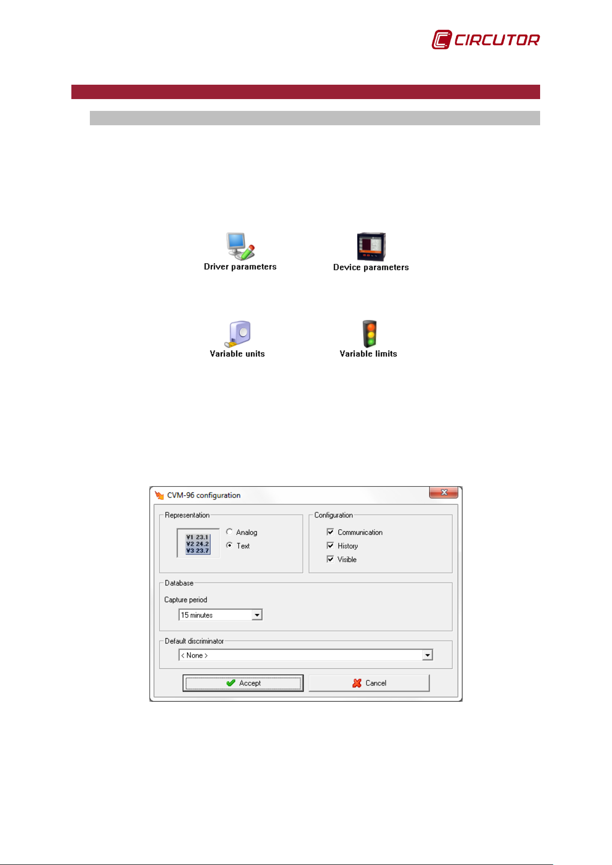
The options menu for a CVM-96 device will be the following:
In this section those options which are common to all or the majority of the drivers are
described.
T hese options are described us ing the CVM-96 device as an example. It is pos sible that other
devices need to configure other types of options, which are not descr ibed in this section, in which case
detailed explanation will be contained in the corresponding device section.
1.1.1 Driver parameters
Fr om this scr een we can configure the variable display type on screen and configure where to
save the data files.
There are two types of data representation.
User Manual 11
Page 12
PowerStudio PowerStudio
12 User Manual
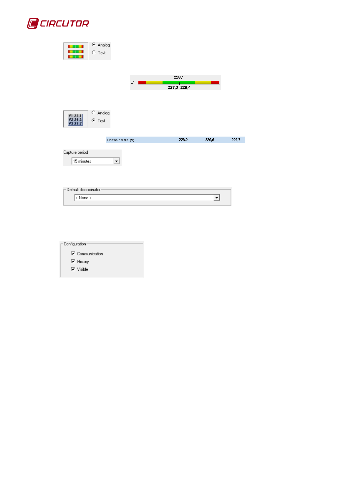
Analogue representation, the variables are graphically represented by bars
as
Where instantaneous value, maximum and minimum values are represented.
interval which elapses between the device history recordings. The periods perm itted are 10, 15, 20 and
30 seconds, 1 minute and multiples up to a maximum of 60 minutes.
default filter to the device. This option appears only in those devices possessing variables that can be
filtered. If we select a filter, when making graphs or tables, the variables are displayed initially as
filtered, although it is also possible to see the variables without the f ilter, or see them through a filter
other than the default one.
Text mode representation, the variables are represented as
The capture period is entered into this field. This indicates the time
This selector will assign a
Using
decide whether or not to save device histories and whether or not to allow a user to see a device from
the client.
we can activate or deactivate communication with a device,
Page 13
PowerStudio
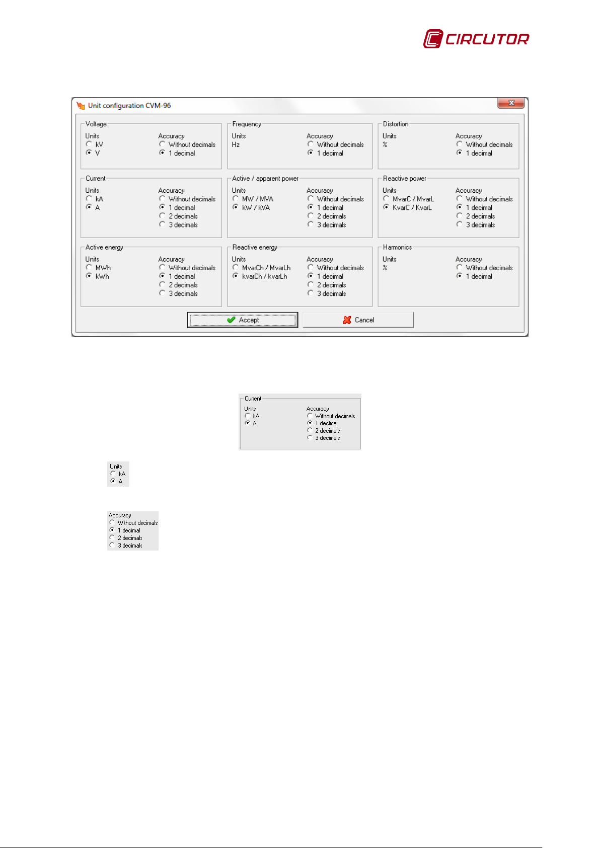
1.1.2 Variable units
Use this dialogue to configure units and the number of decimals with which to display the
variables on screen. This type of configuration only affects the value display on the screen and does
not affect the equipment.
variables will appear in A.
variables are shown with 3 decimals.
The units in which the variables are shown are selected. In this case all the current
The pr ecision when displaying the variables is selected. In this cas e all the current
User Manual 13
Page 14
PowerStudio PowerStudio
14 User Manual
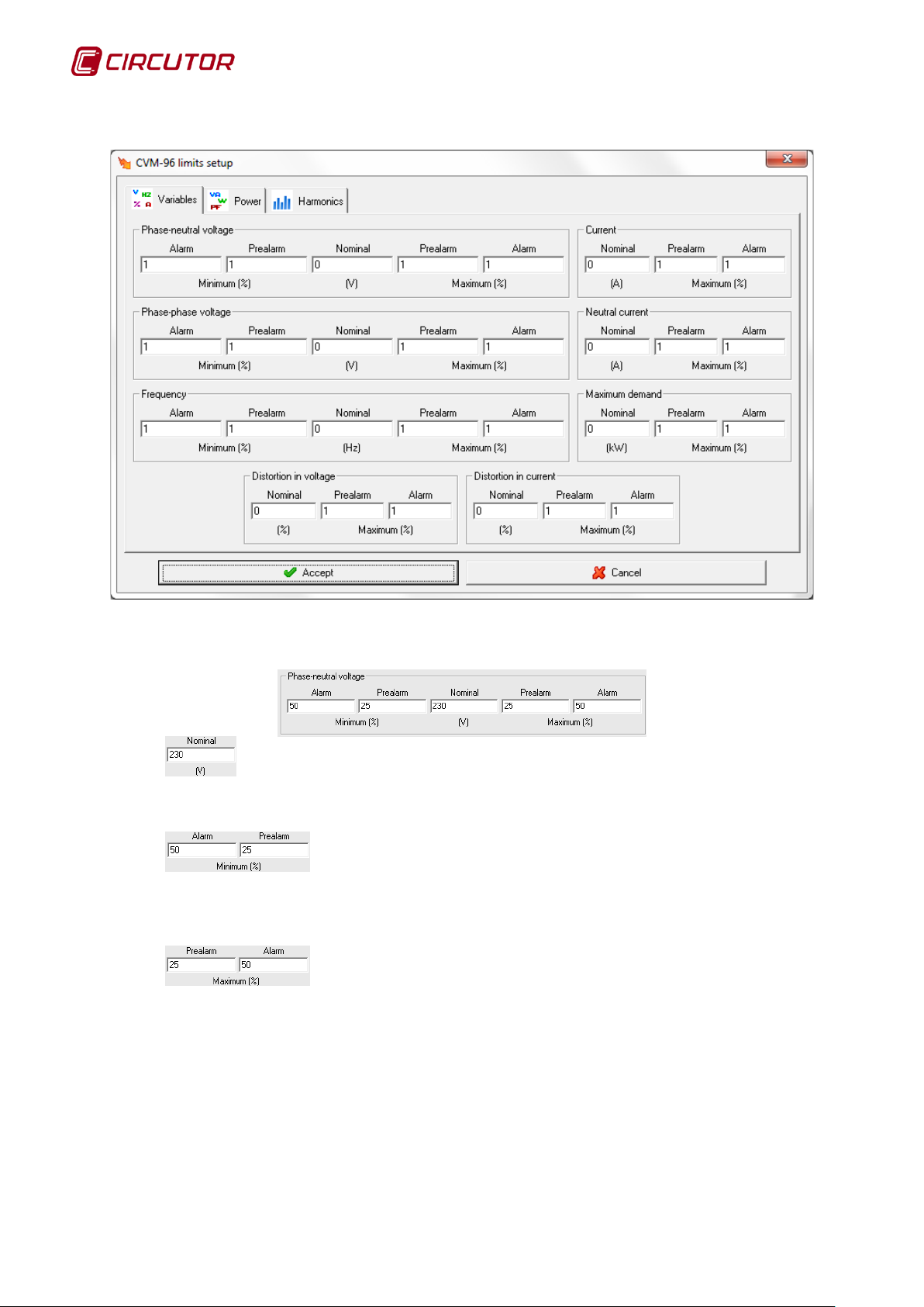
1.1.3 Variable limits
Use this dialogue to configure nominal variable values, as well as a series of margins to
display on screen when a variable measures unusual values.
brackets. If the nominal value is 0, the alarm is disabled. For the power factor, the nominal value
should be 1 to enable the alarm or 0 to disable it.
case when the variable value is between 25% and 50% below the nominal value, there will be a prealarm signal, if it is below 50% the alarm will sound. For the power fac tor the desired alarm and pre–
alarm between +0.0 and -0.0 are entered directly.
case when the variable value is between 25 and 50% above nominal value, there will be a pre-alarm
signal, if it is above 50% the alarm will sound. For the power factor the des ired alarm and pre–alarm
between +0.0 and -0.0 are entered.
If the pre-alarm value is equal to the alarm value, the pre-alarm zone will be disabled, passing
directly from the normal state to the alarm status.
Nominal variable value. The units used to express this value are indicated in
Percentage of nominal value for the pre-alarm or alarm signal. In this
Percentage of nominal value for the pre-alarm or alarm signal. In this
Page 15
PowerStudio
1.2.- AFQ (Active filter)1
1.2.1 Driver options
Options menu:
The ‘Variable units‘ and ‘Variable limits‘ options are explained in detail in sections 1.1.2
Variable Units and 1.1.3 Variable limits, respectively.
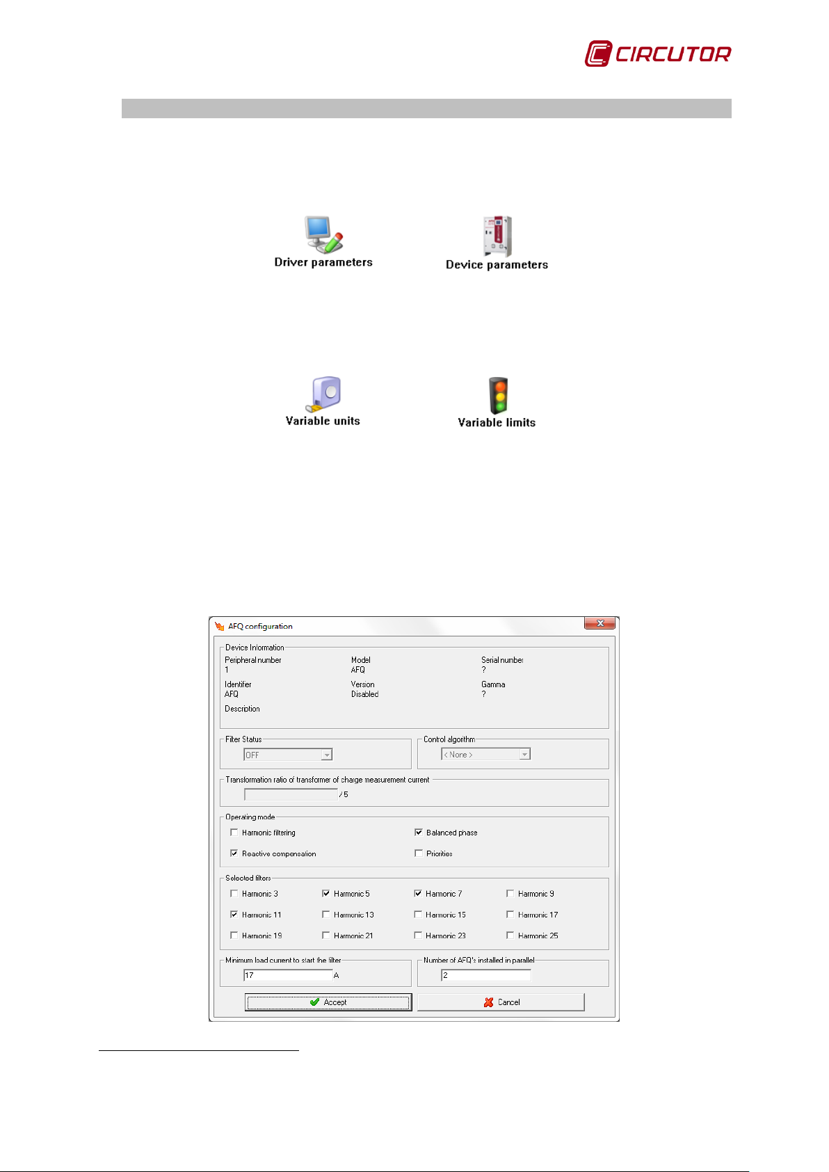
1.2.1.1 Device parameters
This screen allows the internal parameters of the device to be configured. On opening the
dialogue box, the software will read the configuration of the device. W hen com plete, click on "Accept"
for the software to send inf ormation on changes to the device. In no c as e will the information be stored
on the hard drive of the PC.
1
Only in version 3.3 or greater
User Manual 15
Page 16
PowerStudio PowerStudio
16 User Manual
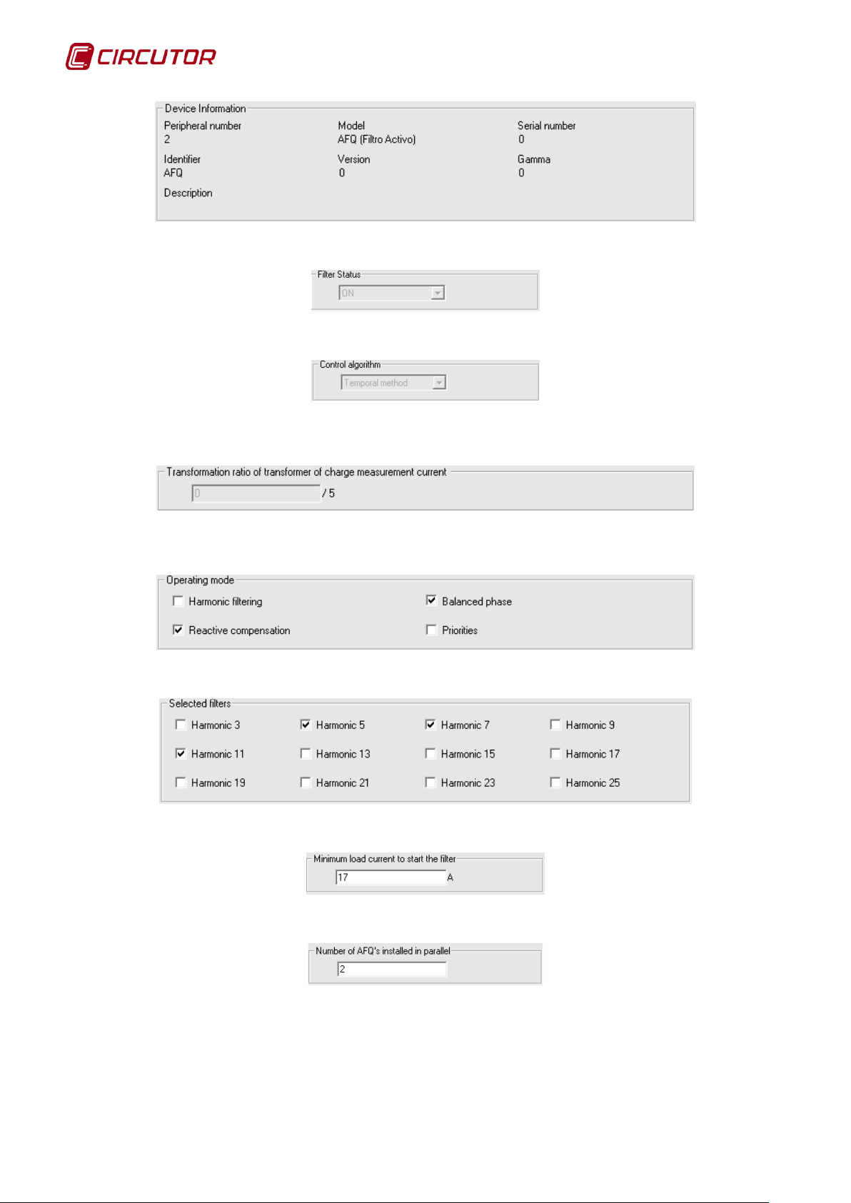
Displays general information about the device.
Displays the filter status, (ON/OFF); this field cannot be edited.
Displays the control algor ithm, there are two options (F requenc y method or Temporal method);
this field cannot be edited.
Displays the transformation ratio for the load current measurement transformer; this field
cannot be edited either.
Configuration of the operating mode; the four modes can be selected at the same time.
Option for selecting harmonics in the selective filtration.
Displays the minimum load current to start the filter.
Displays the number of AFQs installed in parallel; the value must be between 1 and 8,
inclusively.
Page 17

PowerStudio
1.3.- C-14d
1.3.1 Driver options
Options menu:
The ‘Variable units‘ and ‘Variable limits‘ options are explained in detail in sections 1.1.2
Variable Units and 1.1.3 Variable limits, respectively.
1.3.1.1 Device parameters
In the case of C-14d it will not be possible to configure any parameters of the device, only
information about it will be shown.
User Manual 17
Page 18
PowerStudio PowerStudio
18 User Manual
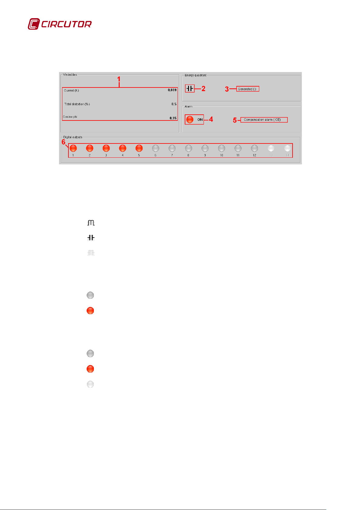
1.3.2 Displaying values
The C-14d device will show the following values screen:
Where:
1. Instant values measured by the device.
2. Energy quadrant.
•
•
•
3. Description that indicates if the energy is consumed or generated.
4. Alarm status:
•
•
5. Description of the enabled alarm. Will not appear if no alarms are enabled.
6. Status of the output relays:
•
•
•
Inductive.
Capacitive.
Cos Phi = 1.
Status OFF. Alarm disabled.
Status ON. Alarm enabled.
Relay disconnected.
Relay connected.
Relay disabled. The relay is not used by the device.
Page 19
PowerStudio
The IP Camera device only allows a captured image to be displayed, either by connecting
It will not be possible to record, display recordings or carry out any other action on the
image displayed, such as motion detection, from the sources described above.
1.4.- IP Camera
directly with a camera with an Ethernet connec tion, a video recorder to which petitions c an
be made or webcams.
The IP Camera device can display images generated from different sources (IP cameras,
videos, webcams, etc.) , provided web requests can be made to these sources and the r esponse is a
still image in JPEG format or video streaming MJPEG format.
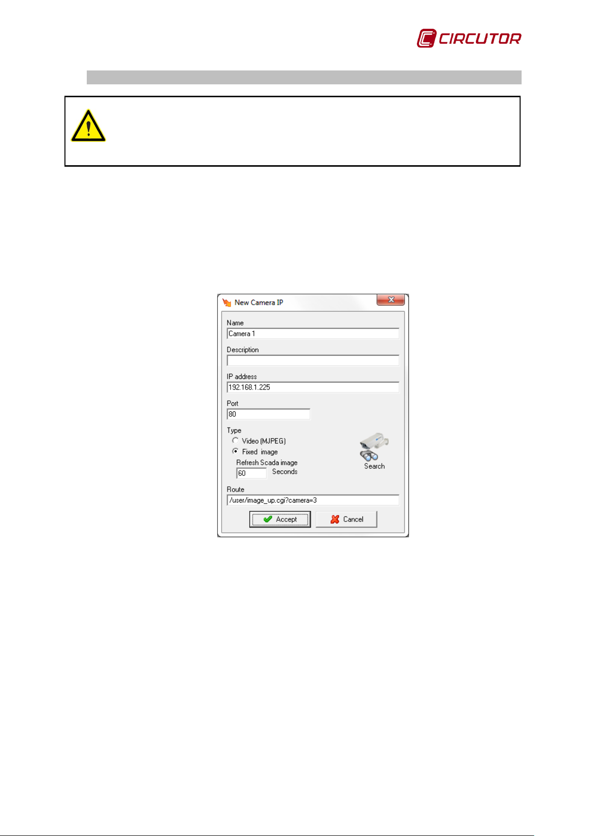
1.4.1 Adding an IP Camera
For more information on how to add a device refer to 'Editor Manual'. The following parameters
are used to configure communication with an IP camera device.
• Name: Alphanumeric f ield that uniquely identifies the device throughout the program.
There are no two devices in the configuration with the same name.
• Description: Enter a brief description of the device using alphanumeric type data.
• IP Address: Corresponds to the address through which the program can
communicate with the device. This parameter can be an IP address or a name.
• Port: Corresponds to the communications port.
• Type: Type of image returned by the device. Video may be displayed in either MJPEG
format or still picture
• Refresh each image: Only used for fixed im ages; dictates how often in seconds the
program should request a new image.
• Route/Request: Corresponds to the request that must be made to the device to
obtain the video or image requested.
User Manual 19
Page 20

PowerStudio PowerStudio
20 User Manual
• Search: By clicking on this button, the program will try to find the device at the address
and port configured, using the most frequent routes / requests.
For more information on which route or request should be used, consult the device m anual
or contact your distributor.
Page 21
PowerStudio
1.5.- TAG READER
1.5.1 Driver options
Options menu:
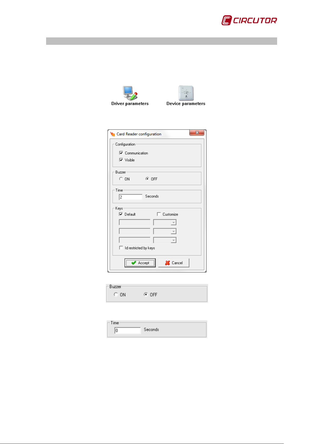
1.5.1.1 Driver Parameters
Activate or deactivate the device buzzer.
Allows you to assign a time in seconds during which the value of the tag read will be kept
before deleting.
User Manual 21
Page 22

PowerStudio PowerStudio
22 User Manual
Configures the read/write keys required to access the cards.
The remaining screen parameters are detailed in section 1.1.1 Driver parameters.
1.5.1.2 Device parameters
This screen allows the internal parameters of the device to be configured. On opening the
dialogue box, the software will read the configuration of the device. W hen com plete, click on "Accept"
for the software to s end inf or mation on changes to the device. In no cas e will the information be stored
on the hard drive of the PC.
Displays general information about the device.
Page 23
PowerStudio
1.6.- CBS-4 /CBS-4 RA
1.6.1 Driver options
Options menu:
1.6.1.1 Device parameters
This screen allows the internal parameters of the device to be configured. Upon opening the
dialogue box, the software will read the device configuration. When com plete, click on ‘Accept’ for the
software to send inform ation on changes to the device. In no c ase will the inform ation be stored on the
hard drive of the PC.
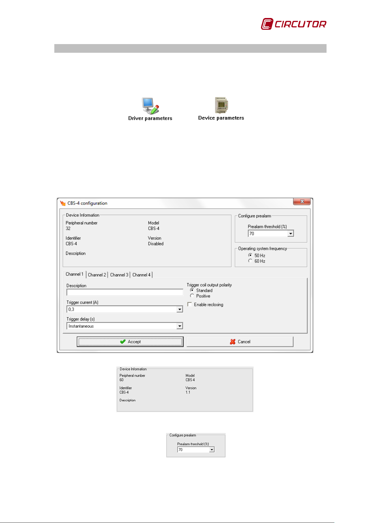
1.6.1.1.1 CBS-4
Displays general information about the device.
Equipment pre-alarm thres hold. This can vary between 50 and 100% of the device channels
minimum trigger threshold.
User Manual 23
Page 24

PowerStudio PowerStudio
24 User Manual
Disabled
0.03 (A)
0.1 (A)
0.3 (A)
0.5 (A)
1 (A)
3 (A)
5 (A)
10 (A)
30 (A)
Instantaneous:
Selective
20 ms
100 ms
200 ms
300 ms
400 ms
500 ms
750 ms
1s
3s
5s
10s
Enables selection of the device connection working network frequency.
Displays the channel configuration.
As it is only possible to display the configuration of one channel at
a time, click on one of the channels to display the corresponding configuration.
Alphanumeric type information where a brief des cription of
the channel can be entered for easy identification.
Indicates the m aximum current that c an be reached by the
device before triggering. The values that can be acquired are:
Channel delay time , the possible values are:
Conf iguration of the polarity of the output relay of the relay output trigger coil,
allowing one of the two options possible to be selected (standard or positive).
If this option is selected, when triggering takes place, the device will try to
reconnect the channel.
Page 25
PowerStudio
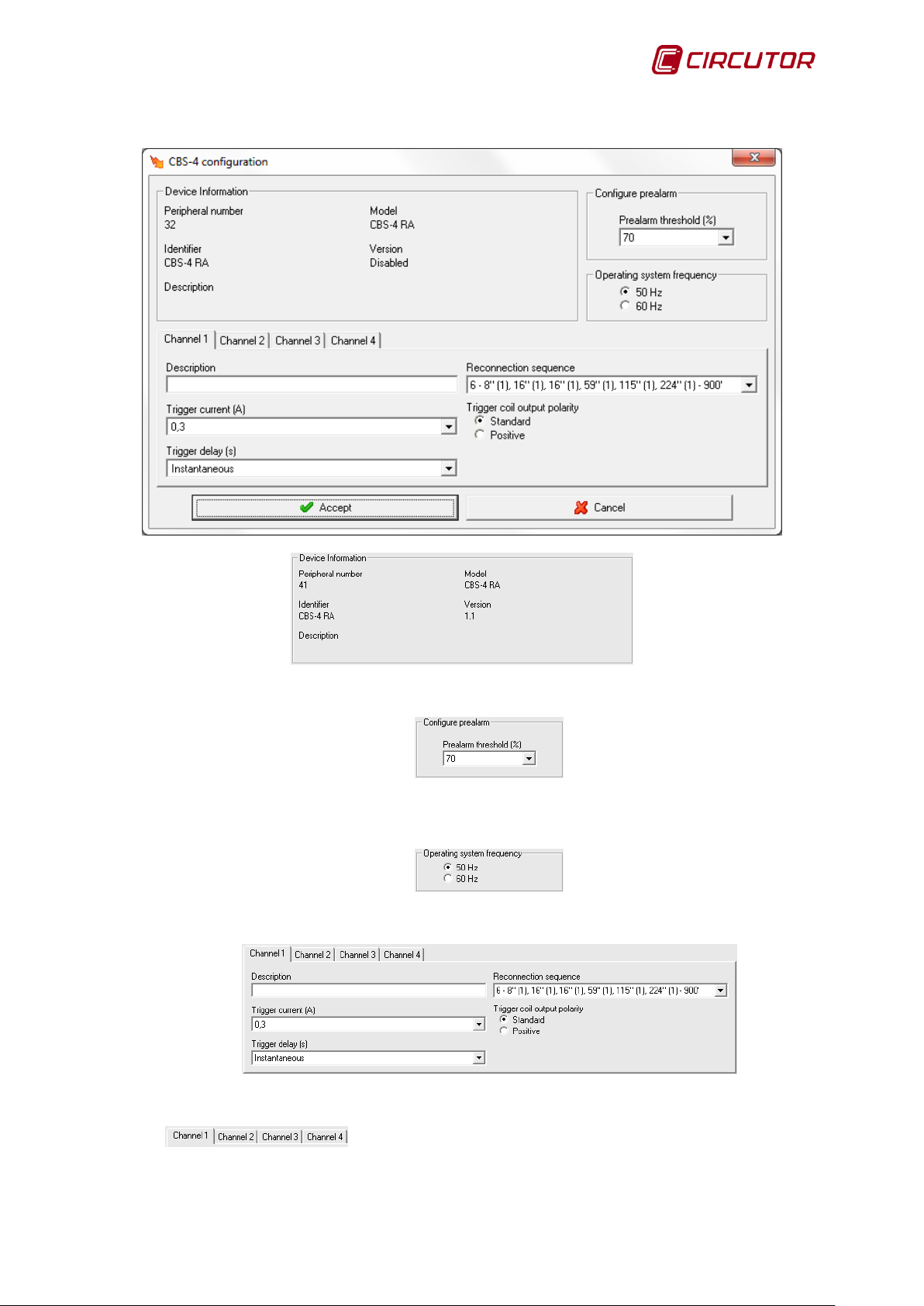
1.6.1.1.2 CBS-4 RA
Displays general information about the device.
Equipment pre-alarm thres hold. This can vary between 50 and 100% of the device channels
minimum trigger threshold.
Enables selection of the device connection working network frequency.
Displays the channel configuration.
As it is only possible to display the configuration of one channel at a
time, click on one of the channels to display the corresponding configuration.
User Manual 25
Page 26

PowerStudio PowerStudio
26 User Manual
Disabled
0.03 (A)
0.1 (A)
0.3 (A)
0.5 (A)
1 (A)
3 (A)
5 (A)
10 (A)
30 (A)
Instantaneous:
Selective
20 ms
100 ms
200 ms
300 ms
400 ms
500 ms
750 ms
1s
3s
5s
10s
Alphanumeric type information where a brief descr iption of
the channel can be entered for easy identification.
Indicates the m aximum current that can be reached by the
device before triggering. The values that can be acquired are:
Channel delay time , the possible values are:
Configuration of the polarity of the output relay of the relay output trigger coil,
allowing one of the two options possible to be selected (standard or positive).
Enables selection of the channel reconnection sequence.
The information displayed will be xx – yy – zz where xx corresponds to the number of reconnections, yy
to the time sequence and zz to the reset time.
Page 27
PowerStudio
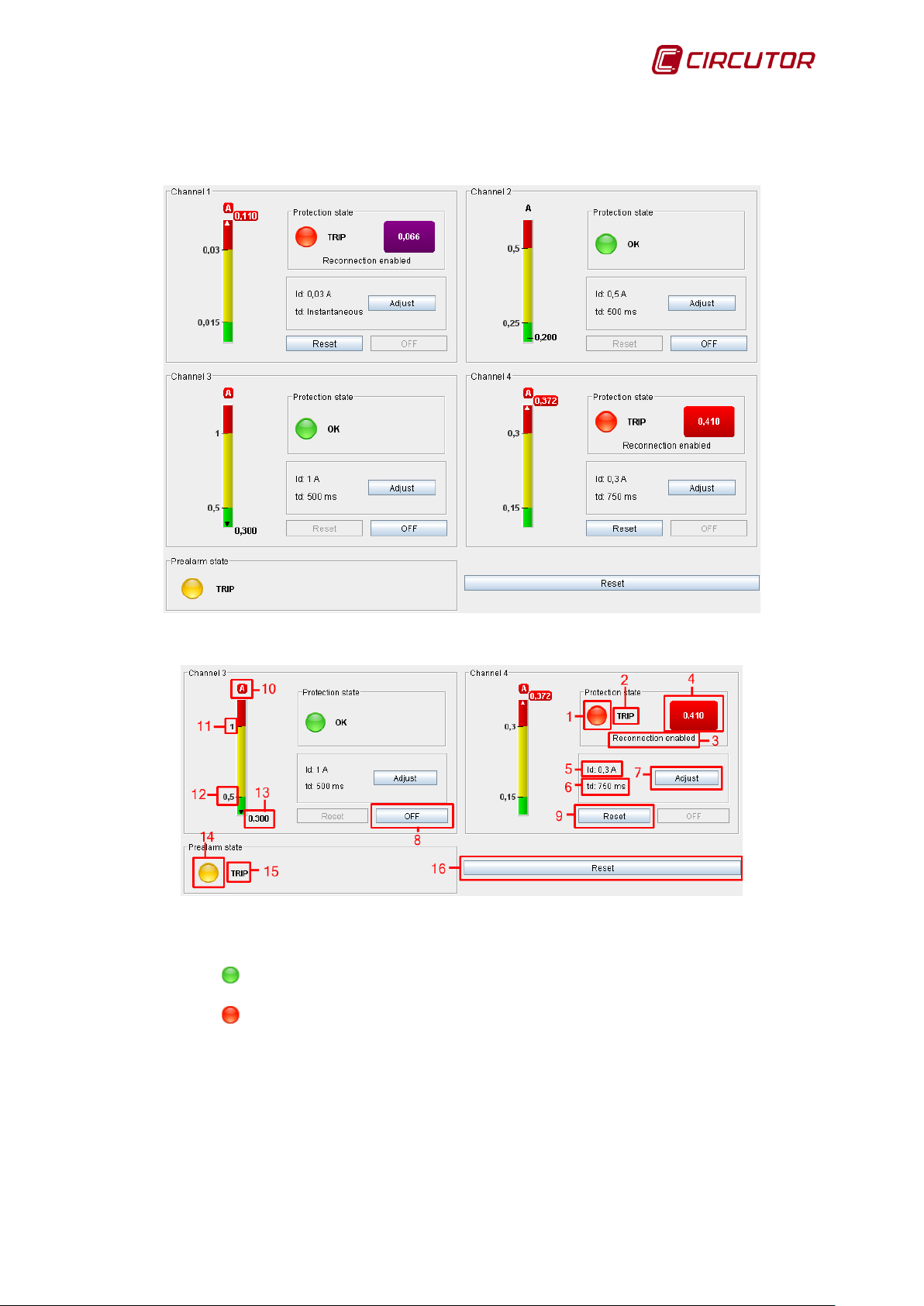
1.6.2 Displaying values
Where:
1. Relay status:
Correct.
•
•
•
Tripped.
2. Protection status:
• Correct. Channel not tripped.
• Toroid error. An error has been detected in the connection with the toroid coil.
• Trip. Channel tripped.
3. Reconnection enabled. Reports that channel reconnections have been enabled.
User Manual 27
Page 28

PowerStudio PowerStudio
28 User Manual
4. Differential current value detected when the channel triggers . If the value detected is twice the
trigger threshold configured it is shown in purple.
5. Trigger current configured.
6. Delay time configured.
7. Adjustment button. Enables programming of sensitivity and channel delay.
8. OFF button. External disconnection of the channel. The button will remain disabled if the
channel has been triggered.
9. Reset button. Push the button to restart the channel.The button will remain disabled if the
channel has not triggered.
10. Current value display units.
11. Channel trigger threshold value configured.
12. Channel pre-alarm value configured.
13. Channel Instantaneous differential current value. W hen the channel instantaneous diff erential
current value exceeds the limits of the values bar, either by excess or default, it will be
indicated as shown in the figure (arrow in the bar).
14. Pre-alarm status:
Disabled status.
•
•
Triggered status.
15. Additional information on the status of the pre-alarm.
16. Reset button. Resets all the device channels that are triggered.
Page 29
PowerStudio
1.7.- CBS-8
1.7.1 Driver options
Options menu:
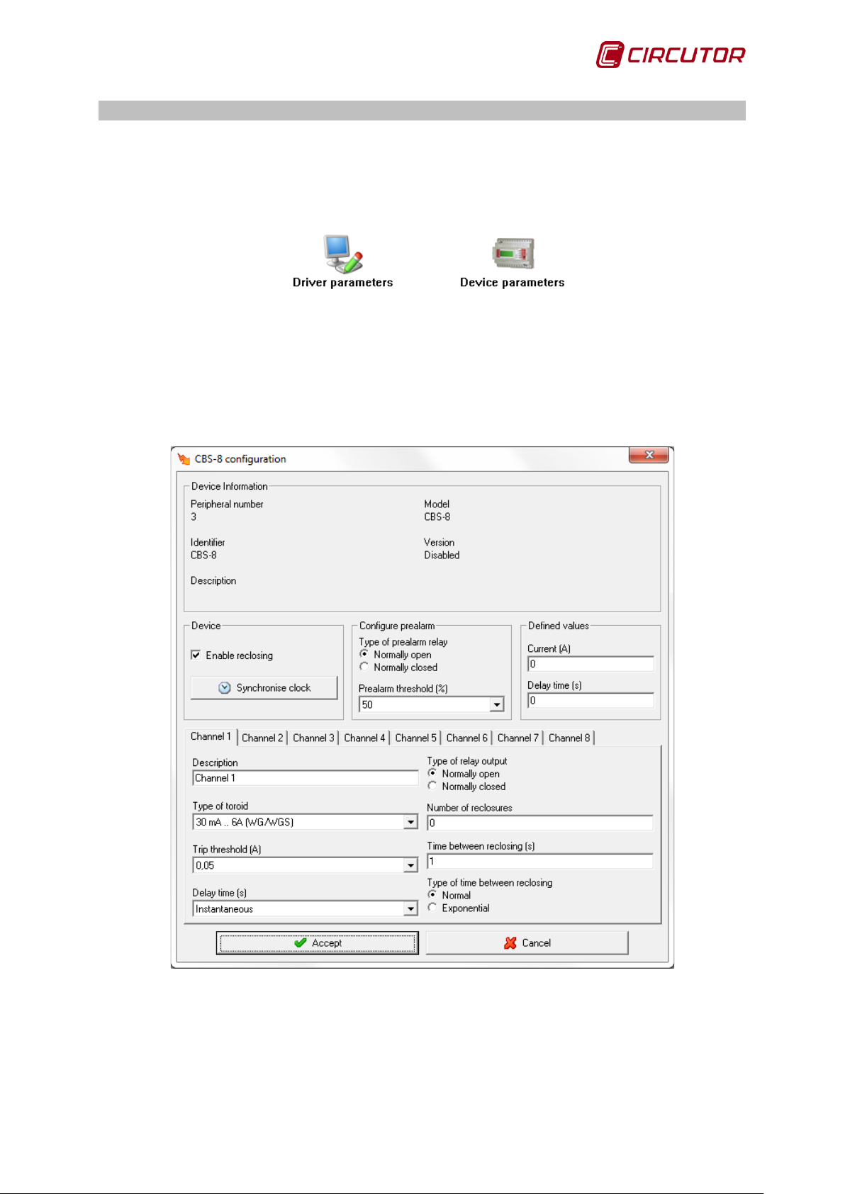
1.7.1.1 Device parameters
This screen allows the internal parameters of the device to be configured. On opening the
dialogue box, the software will read the configuration of the device. W hen com plete, click on "Accept"
for the software to send inf ormation on changes to the device. In no c as e will the information be stored
on the hard drive of the PC.
User Manual 29
Page 30
PowerStudio PowerStudio
30 User Manual
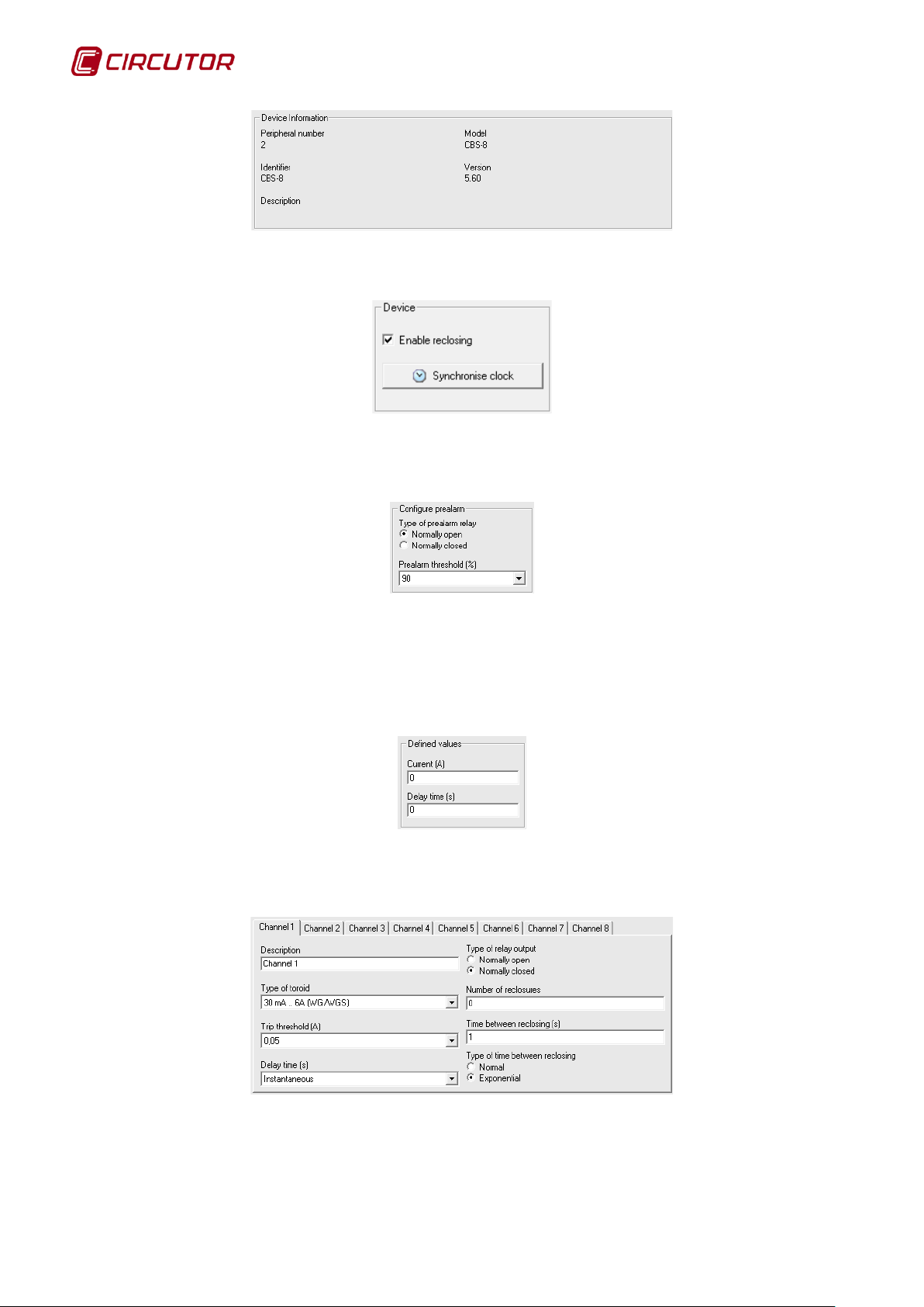
Shows general information.
This selector allows the equipment to have the channel reconnections enabled or not.
Depending on whether the reconnections of the c onf igur ation f ields of the c hannels ar e enabled or not.
Clicking on the button ‘Synchronize clock’ the present time will be sent to the PC.
The following can be configured:
• Type of pre-alarm relay. Operation method of the pre-alarm relay common to all
channels of the device.
• Pre-alarm threshold. Pre-alarm threshold the equipment possesses. This can vary
between 50 and 100% of the minimum trigger threshold of the device channels.
A trigger threshold and a personalized delay time can be configured by the user. These
parameters are com mon to all channels of the device. Depending on the type of channel selected, the
customized threshold may be selected or not.
Shows the channel configuration.
Page 31

PowerStudio
Toroid 30 mA 6… A
Toroid 300 mA 60A ...
30 mA
1 A
300 mA
10 A
50 mA
1.5 A
500 mA
15 A
100 mA
2 A
1 A
20 A
200 mA
2.5 A
2 A
25 A
300 mA
3 A
3 A
30 A
400 mA
3.5 A
4 A
35 A
500 mA
4 A
5 A
40 A
600 mA
4.5
6 A
45 A
700 mA
5 A
7 A
50 A
800 mA
5.5 A
8 A
55 A
900 mA
6 A
9 A
60 A
Customized
1
Customized
Instantaneous:
Selective
0.1 s
0.4 s
0.8 s
1 s
3 s
5 s
10 s
Customized
As it is only possible to display the
configuration of one channel at a time, click on one of the channels to display the corresponding
configuration.
Alphanumeric type information where a brief desc ription of the
channel can be entered to for easy identification.
Toroid type connected to the channel. T here are three possible
options for selection:
• Channel disabled
• Fullscale channel with 6A (30mA .. 6A)
• Fullscale with 60A (300mA .. 60A)
Channel trigger threshold, depending on the type of toroid
connected the values available will be:
1
Only if the value of the cust omized trigger threshold does not exceed 6A
will be locked.
Channel delay time, the possible values are:
Channel output relay operating mode.
Num ber of attem pts at reconnection. After this number the relay
Time interconnections.
Operating mode in the time interconnections.
User Manual 31
Page 32

PowerStudio PowerStudio
32 User Manual
1.7.2 Displaying values
The CBS-8 device will show the following value screen:
Where:
1. Channel status:
Status ON.
•
•
Pre-alarm status.
•
Status OFF.
2. Relay status:
• ON. Non-locked channel.
• OFF. Channel locked.
3. Additional information on the status of the channel:
• Pre-alarm: Pre-alarm enabled
• Reconnection: Channel disconnected with timed reconnection process.
• Remote: Channel disconnected by external triggering, cannot be automatically
reconnected.
Page 33

PowerStudio
4. Reconnection enabled. Reports that channel reconnections have been enabled.
5. Reset button. If the channel is triggered, the button will remain disabled. Push the button to
restart the channel.
6. OFF button. External disconnection of the channel. The button will remain disabled if the
channel has not been triggered.
7. Adjustment button. Enables programming of sensitivity and channel delay. Channel
information is also shown.
8. Channel trip threshold value configured.
9. Channel pre-alarm value configured.
10. Channel instantaneous differential current value.
11. When the channel Instantaneous different ial current value exceeds the limits of the value bar,
either in excess or default, this will be indicated as shown in the figure (arrow below the value).
12. Differential current value detected when the channel triggers.
User Manual 33
Page 34

PowerStudio PowerStudio
34 User Manual
1.8.- CCL
1.8.1 Driver options
Options menu:
The ‘Variable units‘ and ‘Variable limits‘ options are explained in detail in sections 1.1.2
Variable Units and 1.1.3 Variable limits, respectively.
1.8.1.1 Device parameters
This screen allows the internal parameters of the device to be configured. On opening the
dialogue box, the software will read the configuration of the device. W hen com plete, click on "Accept"
for the software to s end inf or mation on changes to the device. In no cas e will the information be stored
on the hard drive of the PC.
Displays general information about the device.
Page 35

PowerStudio
1.8.1.2 Advanced configuration
Allows you to assign a maximum power value to be used by the device.
Allows you to select the device connection mode: single-phase or three-phase.
User Manual 35
Page 36

PowerStudio PowerStudio
36 User Manual
1.9.- CCLEngine
The CCLEngine driver allows the management of one or several CCL devices for vehicle
recharging.
It will allow you to assign the CCL device(s) with a card reader from which recharges will be
authorised and discounted, as well as obtain information on these.
1.9.1 Driver options
Options menu:
The ‘Variable units’ option is detailed in section 1.1.2 Variable Units.
1.9.1.1 Device parameters
From this screen we can c onfigure the par am eters f or the rec har ging that will be performed on
the CCL equipment assigned to this CCLEngine.
Page 37

PowerStudio
The scheduler control allows you to determine the start and end time for recharging performed as
programmed.
Allows you to activate/deactivate the power control.
The equation entered in "Maximum power" allows us to indicate the nominal maxim um power of
the installation to which the CCL devices are connected.
The equation entered into "Ins tantaneous power" allows us to indicate the method for deter mining
the power being consumed at each m oment in order to find out if we can connec t another CCL device
or not. In other words:
- The CCL devices have a nominal power
- In an installation with CCL devices, we can install equipment which indicates the power we are
consuming at any time.
- In the case of activating the power control, before allowing the recharging of a new CCL, the
CCLEngine will check whether the instantaneous power and the nominal power of the CCL
which we are going to use exceed the maxim um power. If this is the case, the CCL will wait to
connect as soon as the instantaneous power consumption drops.
Allows you to activate the configuration of the cost per kWh and maximum amount that can be
discharged in one recharge. This prevents a us er's card from being emptied by mistake, by placing a
limit on the discharge. As with the power control, management of the maximum discharge is optional.
User Manual 37
Page 38

PowerStudio PowerStudio
38 User Manual
This box can be used to assign the reader in which the cards s hould be entered to operate with the
CCL devices assigned to this CCLEngine.
Allows you to enter the list of CCL recharge devices that this CCLEngine will manage.
1.9.2 CCL Engine display
When we view the CCLEngine from the client, the CC Ls which com pris e this are displayed and we are
able to enter a card in the reader, to program or end recharging.
Page 39

PowerStudio
Once the card is entered, we are able to choose the CCL in which we would like to recharge,
and specify the type of recharging (immediate or scheduled).
User Manual 39
Page 40

PowerStudio PowerStudio
40 User Manual
While the card is inserted, the recharge parameters can be viewed, such as the date and start time,
request date, recharge time, power and energy consumed.
When we rem ove the card, the CCLEngine returns to the home s creen, indicating, if pres ent, the CCL
equipment that is recharging at that time.
If we insert a card that has activated a recharge in this CCLEngine, the recharge properties
screen will be displayed again:
Page 41

PowerStudio
we can use this to stop the recharge.
User Manual 41
Page 42

PowerStudio PowerStudio
42 User Manual
1.10.- CIRWATT
1.10.1 Download with protocol IEC 870-5-102
The CIRW ATT device allows load curve and bill closures f iles to be downloaded through the
IEC 870-5-102 protocol. To enable downloading when new equipment is added the "Download files
(IEC 870-5-102)" option must be selected and the gateway, the measuring point address, and
password configured.
From this s creen it is possible to configure the tim e zone where the CIRWATT is locat ed, by
default the time zone of the sof tware will appear but this should be modif ied if a new device is f ound in
a different time zone.
1.10.2 Driver options
Options menu:
The ‘Variable units‘ and ‘Variable limits‘ options are explained in detail in sections 1.1.2
Variable Units and 1.1.3 Variable limits, respectively.
Page 43

PowerStudio
1.10.2.1 Driver parameters
Allows the contracts to be displayed on screen to be selected. Using these selectors the
contracts shown on screen can be s elected. In this cas e the dr iver displays contracts 1 and 3, and will
hide contract 2. These param eters will only affect the screen display of the CIRW AT T device contracts
but not the internal configuration of the CIRWATT device.
The remaining parameters are explained in section 1.1.1 Driver Parameters.
1.10.2.2 Device parameters
T his sc r een will allow a series of internal infor mation and device parameters to be displayed on
screen.
User Manual 43
Page 44

PowerStudio PowerStudio
44 User Manual
Displays general information.
• Voltage transformation ratio: shows the ratio between primary and secondary voltage
programd into the device.
• Power transformation ratio: Shows the ratio between the primary and secondary currents
programd into the device.
1.10.2.3 Contracted power
This screen allows the contracted loads f or each contract and CIR W ATT rat e to be displayed.
It is always be possible to enter contracted power manually, but if the device is IEC enabled it can also
be read directly from the equipment by clicking the button
.
Page 45

PowerStudio
1.10.3 Displaying Contracts
The CIRWATT device shows the following screen when viewing a contract:
Where:
1. Corresponds to the information of a new contract rate.
2. Marks the active rate of the contract.
3. Marks the active quadrant.
indicated in section 1.9.2.1 D river parameters , it is possible to select which contracts we want to view,
and the tab corresponding to the hidden contr acts will not appear. For ex ample if you only want to view
contracts 1 and 3 the tabs will be as follows:
Select the various tabs to display the desired contract. As
User Manual 45
Page 46

PowerStudio PowerStudio
46 User Manual
1.11.- CIRWATT B
1.11.1 Download with protocol IEC 870-5-102
The CIRW ATT B device allows load curve and bill closure files to be downloaded through the
IEC 870-5-102 protocol. To enable downloading when new units are added the "Download files (IEC
870-5-102)" option must be selected and the communication, gateway address, measuring point
address and access key parameters must be configured.
From this s creen it is possible to configure the tim e zone where the CIRWATT is locat ed, by
default the time zone of the sof tware will appear but this should be modif ied if a new device is f ound in
a different time zone.
1.11.2 Driver options
Options menu:
The ‘Variable units‘ and ‘Variable limits‘ options are explained in detail in sections 1.1.2
Variable Units and 1.1.3 Variable limits, respectively.
Page 47

PowerStudio
1.11.2.1 Device parameters
T his sc r een will allow a series of internal infor mation and device parameters to be displayed on
screen.
Displays general information.
• Voltage transformation ratio: shows the ratio between primary and secondary voltage
programmed into the device.
User Manual 47
Page 48

PowerStudio PowerStudio
48 User Manual
• Power transformation ratio: Shows the ratio between the primary and secondary currents
programmed into the device.
Time zone where the device is located.
The configuration of the geographical coordinates will only appear when the device has the
astronomical clock option.
The digital output configuration will only appear when the device has digital outputs. The
number of digital outputs will depend on the device model.
Depending on the function, it will be possible to configure additional parameters associated
with the function selected.
• Function 1: Incoming active energy.
• Function 2: Outgoing active energy.
• Function 3: Reactive energy Q1/Q2.
• Function 4: Reactive energy Q3/Q4.
• Function 5: Maximeter.
Function without additional parameters.
• Function 6: RM in tariff period.
• Function 106: Astronomical.
This function can only be configured in equipment with an astronomical clock.
special days.
Value between 0.1 and 65535 with one decimal.
Contract: Value between 1 and 3.
Tariff: Value between 1 and 9.
You will be able to configure a m axim um of seven
Page 49

PowerStudio
You will be able to define a maximum of eight
operations.
• Function 255: Deactivated.
1.11.2.2 Contracted power
This screen displays the contracted powers . You will always be able to enter the contracted
powers manually and read them directly from the equipment by pressing the
button.
1.11.3 Digital inputs
Some Cirwatt B devices have a built-in digital input card. It will check whether the external
inputs are open or closed and count the number of times they are opened and closed.
Refer to the unit's manual to chec k whether your unit has built-in digital inputs or not. The unit's
firmware version m ust be 01.00.05 or later. Otherwise, the units with digital inputs and earlier
firmware versions will not communicate.
In addition, the variables that count the number of times that digital inputs close cannot be
reset to 0.
User Manual 49
Page 50

PowerStudio PowerStudio
50 User Manual
1.12.- CIRWATT B PREMIUM
1.12.1 Download with protocol IEC 870-5-102
The CIRW ATT B Premium device allows load cur ve and bill closure files to be downloaded
through the IEC 870-5-102 protocol. To enable downloading when a new unit is added, the "Download
files (IEC 870-5-102)" option must be selected and the gateway, the measuring point address, and
access key parameters must be configured.
From this s creen it is possible to configure the tim e zone where the CIRWATT is locat ed, by
default the time zone of the software will appear but this should be m odified if a new device is f ound in
a different time zone.
Page 51

PowerStudio
1.12.2 Driver options
Options menu:
The ‘Variable units‘ and ‘Variable limits‘ options are explained in detail in sections 1.1.2
Unidades de las variables and 1.1.3 Límites de las variables, respectively.
1.12.2.1 Device parameters
This screen will display internal device information and parameters on the screen.
User Manual 51
Page 52

PowerStudio PowerStudio
52 User Manual
Displays general information.
• Voltage transformation ratio: Shows the primary to secondary voltage ratio programmed in
the device.
• Power transformation ratio: Shows the primary to secondary current ratio programmed in
the device.
Time zone where the device is located.
The configuration of the geographical coordinates will only appear when the device has the
astronomical clock option.
The digital output configuration will only appear when the device has digital outputs. The
number of digital outputs will depend on the device model.
Additional parameters assoc iated to the s elected f unc tion c an be configured, depending on the
function:
• Function 1: Incoming active energy.
• Function 2: Outgoing active energy.
• Function 3: Reactive energy Q1/Q2.
• Function 4: Reactive energy Q3/Q4.
•
Value between 0.1 and 65535 with one decimal.
Page 53

PowerStudio
• Function 5: Maximeter.
Function without additional parameters.
• Function 6: RM in tariff period.
•
Contract: Value between 1 and 3.
Tariff: Value between 1 and 9.
• Function 106: Astronomical.
This function can only be configured in units with an astronomical clock.
You will be able to configure a maximum of seven
special days.
You will be able to define a maximum of eight
operations.
• Function 255: Deactivated.
1.12.2.2 Contracted power
This screen displays the contracted powers . You will always be able to enter the contracted
powers manually and read them directly from the unit by pressing the
button.
User Manual 53
Page 54

PowerStudio PowerStudio
54 User Manual
1.12.3 Digital inputs
Some Cirwatt B’s have a built-in digital input card. It will check whether the external inputs are
open or closed and count the number of times they are opened and closed.
Refer to the unit's manual to chec k whether your unit has built-in digital inputs or not. The unit's
firmware version m ust be 01.00.05 or later. Otherwise, the units with digital inputs and earlier
firmware versions will not communicate.
In addition, the variables that count the number of times that digital inputs close cannot be
reset to 0.
Page 55

PowerStudio
1.13.- CDR-8
1.13.1 Driver options
Options menu:
1.13.1.1 Device parameters
This screen allows the internal parameters of the device to be configured. On opening the
dialogue box, the software will read the configuration of the device. W hen com plete, click on "Accept"
for the software to s end inf or mation on changes to the device. In no cas e will the information be stored
on the hard drive of the PC.
User Manual 55
Page 56

PowerStudio PowerStudio
56 User Manual
Shows general information.
The following can be configured:
• Type of pre-alarm relay. Operation method of the pre-alarm relay common to all
channels of the device.
• Pre-alarm threshold. Pre-alarm threshold the equipment possesses. This can vary
between 50 and 100% of the minimum trigger threshold of the device channels.
A trigger thr eshold and a user-personalized delay time can be configured by the user. These
parameters are com mon to all channels of the device. Depending on the type of channel selected, the
customized threshold may be selected or not.
This selector allows the equipment to have the channel reconnections enabled or not.
Depending on whether the reconnections are enabled or not, some of the channel configuration fields
will be enabled or disabled. Clicking on the ‘Synchronize clock’ button the present PC tim e will be sent
to the device.
% O f hysteresis for the connection and disc onnection of the channel configured in the relay
mode.
Shows the channel configuration.
configuration of one channel at a time, click on one of the channels to display the corresponding
configuration.
As it is only possible to display the
Page 57

PowerStudio
Toroid 30 mA...6A
Toroid 300 mA 60A ...
30 mA
1 A
300 mA
10 A
50 mA
1.5 A
500 mA
15 A
100 mA
2 A
1 A
20 A
200 mA
2.5 A
2 A
25 A
300 mA
3 A
3 A
30 A
400 mA
3.5 A
4 A
35 A
500 mA
4 A
5 A
40 A
600 mA
4.5 A
6 A
45 A
700 mA
5 A
7 A
50 A
800 mA
5.5 A
8 A
55 A
900 mA
6 A
9 A
60 A
Customized
1
Customized
Instantaneous:
Selective
0.1 s
0.4 s
0.8 s
1 s
3 s
5 s
10 s
60 s 1
Customized
0.1 s
0.4 s
0.8 s
1 s
3 s
5 s
10 s
60 s
Customized
Alphanumeric type information where a brief description of the
channel can be entered for easy identification.
Toroid type connected to the channel. There are three possible
selection options:
• Channel disabled
• Fullscale channel of 6A (30mA .. 6A)
• Fullscale channel of 60A (300mA .. 60A)
Channel operating mode. Depending on the selected mode, some of the
configuration options of the channel may be disabled.
Channel output relay operating mode.
Channel triggering threshold, depending on the type of toroid
connected the available values will be:
1
Only if the value of the cust omized trigger threshold does not exceed 6A
possible values are:
1
Only if the channel works on the relay mode
mode, the possible values are:
Channel lock selection when working on the relay mode.
User Manual 57
Channel delay time, depending on the selected operating m ode, the
Delay time in the channel reset when working on the relay
Page 58

PowerStudio PowerStudio
58 User Manual
Triggering selection; low current (LOW ) or overcurrent (HIG H) of the channel when
working in relay mode.
be locked.
Operating mode in the time interconnections.
Number of attempts at reconnection. After this num ber the relay will
Time interconnections.
1.13.2 Displaying values
The CDR-8 device will display the following screen values:
Where:
Page 59

PowerStudio
1. Channel status:
•
Status ON.
•
Pre-alarm status.
•
Status OFF.
2. Relay status:
• ON. Unlocked channel.
• OFF. Locked channel.
3. Channel operating mode:
Differential mode.
•
•
Relay mode.
4. Additional information on the status of the channel:
• Pre-alarm: Pre-alarm enabled.
• Reconnection: Channel disconnected with timed reconnection process.
• Remote: Channel disconnected by external triggering, cannot be automatically
reconnected.
5. Additional channel information:
• Reconnection enabled: Reports that channel reconnections have been enabled. Only
if the channel is in differential mode.
• Channel can be locked. Reports t hat the channel will remain lock ed when trigged, with
manual or remote reset being necessary. Only if the channel is in relay mode.
6. Reset button. If the channel is triggered, the button will remain disabled. Push the button to
restart the channel.
7. OFF button. External disconnection of the channel. The button will remain disabled if the
channel has not been triggered.
8. Adjustment button. Enables programming of sensitivity and channel delay. Channel
information is also shown.
9. Channel instantaneous differential current value. W hen the channel Instantaneous differential
current value exceeds the limits of the value bar, either in excess or default, this will be
indicated as shown in the figure (arrow below the value).
10. Channel trip threshold value configured.
11. Channel pre-alarm value configured.
12. Differential current value detected when the channel triggers.
User Manual 59
Page 60

PowerStudio PowerStudio
60 User Manual
1.14.- Client OPC2
This PowerStudio driver allows a OPC-DA client to be configured to access the variables
accessible on a OPC-DA server.
Onc e the variables to be read have been configured, the OPC client will behave in a manner
similar to other devices with which the program communicates.
1.14.1 OPC connection configuration
To add a new OPC client the OPC server to which it has access must be indicated.
Pressing button
We may select a local server that has previously been configured on our machine, or enter the IP
address of a machine on the local network to seek all the OPC servers that it may have configured.
The OPC specifications s upported by the client are “Data Access V1”, “Data Acces s V2” and “Data
Access V3”.
brings up a dialogue to conveniently select the OPC server.
2
Only in Deluxe version
Page 61

PowerStudio
1.14.2 Driver options
Options menu:
The ‘Variable units‘ and ‘Variable limits‘ options are explained in detail in sections 1.1.2
Variable Units and 1.1.3 Variable limits, respectively.
1.14.2.1 Device parameters
This screen is used to configure the variables that should be requested from the OPC server.
User Manual 61
Page 62

PowerStudio PowerStudio
62 User Manual
General OPC client information.
OPC client variable Configuration. See 1.14.2.1.1 Numeric variables.
Allows loading of a variable configuration that was
previously saved to disk. This option is useful when the same variables have to be configured on
several OPC clients.
Allows the variable configuration to be saved to disk, so
that it can subsequently be loaded on another OPC client.
1.14.2.1.1 Variables
Pushing the “Add" or “Modify” button brings up a dialogue to configure the variable.
Page 63

PowerStudio
• Identifier: Allows each of the binary variables to be used in expressions and conditions to be
identified, see 'Editor Manual'.
• Name: Variable name, used to better identify it.
• Description: Short description of the variable.
• Group: Identifier of the group the variable belongs to in the OPC server.
• Item: Identifier of the item the variable belongs to in the OPC server.
• Others: Different variable configuration parameters:
o Save: Indicates whether or not the server value read should be saved in the value log.
o Incremental: Indicates whether the value of the variable displayed is incremental.
Typical energy variable option to see increments.
o Analogue variable: Indicates whether or not the variable to be read is analogue type.
o Zero: Value of the parameter to which the zero of the scale is assigned.
o Fullscale: Value of the parameter to which the maximum value of the scale is
assigned.
o Type: Type of output, allows between 0-20 mA, 4-20 mA or 0 -? V, depending on the
device.
• Accuracy: Number of bits in the sample.
User Manual 63
Page 64

PowerStudio PowerStudio
64 User Manual
• Format: Variable data format indicated.
o Or iginal: Based on how the variable is configured on the OPC server one conversion
or another will be made.
VT_R4 handled as floating type value.
VT_UI4 handled as integer value with no symbol.
VT_R8 handled as double type value.
Any other type will display the value converted into a string.
o Forced: Indicate whether or not the variable has a symbol and the number of
decimals.
• Type: Selects the type of variable; i.e., read, write or both. If the variable is write or read/write
the value can be forced on the device.
• Grouping criteria: Enables the variable values grouping criteria to be selected in graphs,
tables, reports and the value to be saved in the values register . For example, if in the period
between saving information we have 3 values (10, 12 and 7) these will be saved in the log
register.
Maximum value. The maximum value of 3 (12) will be saved
Minimum value: The minimum value of 3 (7) will be saved.
Average value: The average value of 3 ((10 + 12 + 7) / 3 = 9.66) will be saved.
Last value: The last value will be saved (7).
Sum of the values: The last value will be saved (7).
In the case of clusters of values in graphs, tables and reports the same criteria will be followed,
except when it is the sum m ation of values, where the s um of 3 values is s hown (10 + 12 + 7 =
29).
• Units: Units in which the value is expres sed. You can select one of the predefined units or
define a new user unit.
• Use: Shows where the variable may be used in the rest of the program.
• Select variables: Pressing the
selection dialogue of the previously configured OPC server, and all the groups and item s that
can be accessed from it are displayed.
button brings up the variables
Page 65

PowerStudio
1.15.- CLIENT POWERSTUDIO3
The PowerStudio client driver allows PowerStudio devices and variables to be accessed when
running on a remote machine.
Onc e the variables to be read have been configured, the PowerStudio client will behave in a
manner similar to other devices with which the program communicates.
1.15.1 PowerStudio client device configuration
Use the devices menu to add a new PowerStudio client as a first level device.
As shown in the previous dialogue, the address and port of the rem ote PowerStudio server to
which we want to connect must be indicated, and also the user and password if authentication is
enabled.
The ‘Download variables from all the machines’ option may be chosen, in which case all
machines and variables accessible in remote PowerStudio will automatically be downloaded. If this
option is not set, each variable must be added manually.
The ‘Download dates previous to the current date when the device is star ted’ option will show
the number of days before the current date for which the files will be downloaded since
communications are established with the unit for the first time.
3
Only in Deluxe version
User Manual 65
Page 66

PowerStudio PowerStudio
66 User Manual
1.15.2 Driver options
Options menu:
The ‘Variable units‘ and ‘Variable limits‘ options are explained in detail in sections 1.1.2
Variable Units and 1.1.3 Variable limits, respectively.
1.15.2.1 Driver Parameters
Allows the display of remote events in the client to be activated.
On activating the display of remote events the c onfiguration of remote events will be enabled;
here you can activate the types of events you want to receive and you can test communication with the
remote equipment. These events can be displayed in the client in the same way as local events.
Page 67

PowerStudio
The remaining screen parameters are detailed in section 1.1.1 Driver parameters.
1.15.2.2 Device parameters
This screen is used to configure the variables that should be requested from the remote PowerStudio.
General PowerStudio client information.
The unit's firmware version can be manually updated by selecting the file with the ‘upgrade’ extension.
User Manual 67
Page 68

PowerStudio PowerStudio
68 User Manual
PowerStudio client variables configuration.
Allows loading of a variables configuration that was
previously saved to disk. This option is useful when the same variables have to be configured on
several PowerStudio clients.
Allows the variable configuration to be saved to disk, so
that it can subsequently be loaded on another PowerStudio client.
1.15.2.2.1 Variables
When the ‘Add’ button is press ed a tree of the rem ote PowerStudio devices will appear. When
a device is selected, its variables selection screen will appear, and the desired variables may be
added.
Page 69

PowerStudio
As an exam ple of variables selec tion screen we have that of an ‘CVM’ where we can see that
the ‘Neutral Phase Voltage’ and ‘Phase-Phase Voltage’ variables have been selected.
User Manual 69
Page 70

PowerStudio PowerStudio
70 User Manual
1.16.- COMPUTER PLUS
1.16.1 Driver options
Options menu:
The ‘Variable units‘ and ‘Variable limits‘ options are explained in detail in sections 1.1.2
Variable units and 1.1.3 Variable limits, respectively.
1.16.1.1 Device parameters
T his screen allows the device alarms to be conf igured. Upon opening the dialogue box, the
software will read the device configuration. W hen complete, click on ‘Accept’ for the sof tware to send
information on c hanges to the device. In no c ase will the inform ation be stor ed on the hard drive of the
PC.
Page 71

PowerStudio
Depending on the device connected, some fields will be disabled.
Displays general information.Among other parameters the current connection configuration
may be seen.
• Voltage transformation ratio: Primary and secondary voltage programming. T he product of
the primary value and the primary current must be the same as or less than 20,000,000.
• Current transformation ratio: This is the device primary current value. Value may be
between 1 and 30,000 A. The secondary current is 1A or 5A.
• Capacitor power measure transformation ratio : The primary capacitor current measure
value may be between 1A and 999A. The secondary capacitor current measure value m ay be
between 1A and 5A.
Machine connect ion and registr ation tim es. For the T F, T F -C and T F-C DI m odels the units ar e
cycles, for the rest of models the units are seconds.
Configuration of the inductive phi or capacitative cosine.
Clicking the button resets the device energy counters to zero.
Clicking the button sends the PC's time of day to the machine.
User Manual 71
Page 72

PowerStudio PowerStudio
72 User Manual
From the alarms tab we can see how the alarms are configured for temperature, voltage,
differential current, ic loss, non-compensated Kvar, phi cosine, low current, thdv, thdixi, thdi step and
thdic.
• Output: This field shows whether the output is conf igured as normally open, normally closed
or disabled.
• Max: In this box the maximum alarm value is indicated.
• Min: In this box the minimum alarm value is indicated.
• Relay: Allows one to indicate whether or not the alarm is associated with the global alarm s
relay.
From the capacitors tab the numeric capacity value of the 16 capacitors and their kVar or MVar
units, voltage value and their V or kV units, the DELTA or WYE connection type and the type of PH-PH
or TRIPH compensation may be seen.
Page 73

PowerStudio
1.17.- COMPUTER SMART
1.17.1 Driver options
Options menu:
The ‘Variable units‘ and ‘Variable limits‘ options are explained in detail in sections 1.1.2
Variable Units and 1.1.3 Variable limits, respectively.
1.17.1.1 Device parameters
This screen allows the internal parameters of the device to be configured. On opening the
dialogue box, the software will read the configuration of the device. W hen com plete, click on "Accept"
for the software to s end inf or mation on changes to the device. In no cas e will the information be stored
on the hard drive of the PC.
User Manual 73
Page 74

PowerStudio PowerStudio
74 User Manual
None of the fields in this dialogue box are editable.
Displays general information about the device.
Displays the value and type of cosine phi. The type may be inductive or capacitive and the
value will be between 0 and 1.
Displays the value of the C/K variable; this value should be between 0 and 1.
Displays the program value, which can be “1111” or “1222” or “1244” or “1248” or “1122”.
Displays the action delay time in seconds; this value can be between 0 and 1000.
Displays the number of steps + 1.
Displays the phase; its values are t1 to t6.
Displays the value of the primary current; these values can range from 0 to 9999.
Page 75

PowerStudio
Displays the display status (ON or OFF).
Displays the backlight % value; values between 0 and 100.
User Manual 75
Page 76

PowerStudio PowerStudio
76 User Manual
Displays the status, lim it and reset of the lleak alarm . The possible limit values are between 0
and 1500.
Displays the c osine limit, I lim it and the cosine type and cosine alarm. The pos sible values for
the cosine limit ar e from 0 to 1, those of the I lim it are between 0 and 9999, and cosine type can be
inductive or capacitive.
Displays the value of the limits for the TH D V and THD I alarm s in % and that f or tem perature
in ºC; temperature values can be between 0 and 256.
For each of the 16 alarms, it displays whether it is enabled and the associated relay.
It shows the status of each of the 12 capacitors; the status can be Auto, On or Off.
Page 77

PowerStudio
1.18.- RS232/485 CONVERTER
The RS232/485 converter connects equipm ent which work s with an RS-485 s erial connection to
the port of the PC with an RS-232 connection.
When adding or modifying this device, see ‘Editor Manual’, the following dialogue appears
Where
• Name: Alphanumeric field that uniquely identifies the device throughout the program . There
are no two devices in the configuration with the same name.
• Description: Alphanumeric type data to enter a brief description of the device.
• Port: Number of the serial port that the program uses for communication with the device.
• Advanced communication: Permits the configuration of a series of additional parameters on
the device. Refer to ‘Editor manual’.
User Manual 77
Page 78

PowerStudio PowerStudio
78 User Manual
For a TCP2RS device to be able to comm unicate through a router, perform the following
N.B.: For information on re-addressing ports consult the router user manual.
1.19- TCP2RS CONVERTER
The TCP2RS converter c onnects equipment units that work with serial comm unication (RS-232
/ RS-485) to an Ethernet network using the IP protocol.
When adding or modifying this device, see ‘Editor Manual’, the following dialogue appears
Where
• Name: Alphanumeric field that uniquely identifies the device throughout the program . There
are no two devices in the configuration with the same name.
• Description: Alphanumeric type data to enter a brief description of the device.
• Address converter: Corresponds to the addres s the program uses to com municate with the
device. This param eter c an be an IP address or a nam e.T his address s hould not be confused
with the MAC address.
• Port: Corresponds to the communications port:
• Configuration port: Corresponds to the communication port the program us es to configure
the device. This port is 30718 by default.
steps:
1-In the ‘Address converter‘ field enter the router's IP address.
2 - In the ‘Port” field enter the com munications port and redirec t this port on the rout er to the
device's communications port.
3 - Redirect the configuration port on the router to port 30718 of the converter.
• Parameters: By clicking the button a dialogue will appear where a number of parameters of
the device can be configured.
Page 79

PowerStudio
Where:
- IP address: Corresponds to the IP address used to communicate with the device.
- Subnetwork mask: Corresponds to the s ubnetwork mask used on the network where the
device is connected
- Predetermined Gateway: Corresponds to the address of the gateway if the device is not on
the same network as the computer containing the program.
- Obtain an IP address automatically (DHCP): T his option will be enabled when we want the
device to automatically receive the IP address via a DHCP server.
- Port: Corresponds to the device communications port.
• Advanced communication: Permits the configuration of a series of additional parameters on
the device. Refer to ‘Editor manual’.
On adding or modifying the device, the software will try to detect it. If it is unable to detect it, if the
device is new or has not been allocated an IP address or has an allocated IP different to that entered in
the ‘Converter Address’, it will ask if you want to assign a new IP address to the converter.
It will only be possible to assign an IP address to the device if it is on the sam e network as
the computer running the program.
If the answer is ‘Yes’, the following dialogue box will appear, which will permit an IP address to
be assigned to the device.
User Manual 79
Page 80

PowerStudio PowerStudio
80 User Manual
Where:
• Physical address (MAC): Ethernet addr ess that eac h device has , which is unique and distinc t
on all network devices. The hardware address that any network interf ace has. Will be of the
type 00-20-4A-61-05-19.
• IP address: IP Address to be allocated to the device that has the physical address introduc ed
in the previous field.
If it is possible to assign an IP address to the converter, the following dialogue box will appear:
To finish setting up the rest of the parameters for communication with the device.
Page 81

PowerStudio
Unlike TCP2RS devices, the program does not configure any Modbus TCP device
device configuration is correct. To configure or assign an IP address to Modbus TCP
For a TCP2RS device to be able to comm unicate through a router, perform the following
N.B.: For information on re-addressing ports consult the router user manual.
1.20.- TCP2RS MODBUSTCP CONVERTER
The TCP2RS conver ter connects equipment which works with serial communication (R S-232 /
RS-485) to an Ethernet network using the IP protocol (ModbusTCP for connection–oriented
communications).
When adding or modifying this device, see ‘Editor Manual’, the following dialogue appears
Where
• Name: Alphanumeric field that uniquely identifies the device throughout the program . There
are no two devices in the configuration with the same name.
• Description: Alphanumeric type data to enter a brief description of the device.
• Address converter: Corresponds to the addres s the program uses to com municate with the
device. This param eter c an be an IP address or a nam e.T his address s hould not be confused
with the MAC address.
• Port: Corresponds to the communications port:By default the Modbus TCP protocol will
communicate through port 502.
• Configuration port: Corresponds to the communication port the program us es to configure
the device. This is port 30718 by default.
parameters automatically, using the configuration port only to detect and verify that the
devices, consult the device manual.
steps:
1 – In the ‘Address converter‘ field enter the router's IP address.
2 – In the ‘Port” f ield enter the c ommunications por t and redir ect this por t on the r outer to the
device's communications port.
3 – Redirect the configuration port on the router to port 30718 of the converter.
User Manual 81
Page 82

PowerStudio PowerStudio
82 User Manual
There are some sec ond-tier devices that when connecting to a Modbus TCP device require
TCP connection are specified in the corresponding sections of each device.
manual configuration, the communication is limited to display, for Modbus TCP these
devices cannot be configured. Devices of this nature are:
- CVM – B / BD
- CVMK
- CVMK – HAR
The special characteristics, as well as the pertinent configuration to carry out correct Modbus
• Parameters: Click ing the button will cause a dialogue will appear where a number of device
parameters can be configured.
Where:
- IP address: Corresponds to the IP address used to communicate with the device.
- Subnetwork mask: Corresponds to the s ubnetwork mask used on the network where the
device is connected
- Predetermined Gateway: Corresponds to the address of the gateway if the device is not on
the same network as the computer containing the program.
- Obtain an IP address automatically (DHCP): T his option will be enabled when we want the
device to automatically receive the IP address via a DHCP server.
• Advanced communication: Permits the configuration of a series of additional parameters on
the device. Refer to ‘Editor manual’.
On adding or modifying the device, the software will try to detect it. If it is unable to detect it, if the
device is new or has not been allocated an IP address or has an allocated IP different to that entered in
the ‘Converter Address’, it will ask if you want to assign a new IP address to the converter.
Page 83

PowerStudio
It will only be possible to assign an IP address to the device if is on the sam e network as the
computer running the program.
If the answer is ‘Yes’, the following dialogue box will appear, which will permit an IP address to
be assigned to the device.
Where:
• Physical address (MAC): Ethernet addres s that eac h device has , which is unique and dist inct
on all network devices. The hardware address that any network interf ace has. Will be of the
type 00-20-4A-61-05-19.
• IP address: IP Address to be allocated to the device that has the physical address introduc ed
in the previous field.
If it is possible to assign an IP address to the converter, the following dialogue box will appear:
To finish setting up the rest of the parameters for communication with the device.
User Manual 83
Page 84

PowerStudio PowerStudio
84 User Manual
1.21.- TCP2RS QNA RS485 CONVERTER
The TCP2RS QNA RS485 converter connects QNA devices which work with serial
communications RS-485 on an Ethernet network using IP protocol.
Due to the peculiarities of the comm unication with QNA devices, only QNA-412 and QNA-413
second-level devices will be able to be connected to TCP2RS QNA RS485 first-level devices.
For more information on how to add and configure this device see section 1.19 TCP2RS
converter.
Page 85

PowerStudio
Due to the large number of converters that can be found on the market. On adding this
For more information on how to configure the converter consult the device manual.
1.22.- GENERIC UDP CONVERTER4
The generic UDP c onverter connects devices that use serial com munic ations (RS-232/RS-485)
to an Ethernet network using the IP protocol (UDP for datagram communications).
Where
• Name: Alphanumeric field that uniquely identifies the device throughout the program. There
are no two devices in the configuration with the same name.
• Description: Alphanumeric type data to enter a brief description of the device.
• Address converter: Corresponds to the addres s the program uses to com municate with the
device. This param eter c an be an IP address or a nam e.T his address s hould not be confused
with the MAC address.
• Port: Corresponds to the communications port:
• Advanced communication: Permits the configuration of a series of additional param eters on
the device. Refer to ‘Editor manual’.
device the program will not attempt to detect or verify that the configuration is correct.
The configuration and the proper functioning of com munications between the converter and
the program is the responsibility of user.
4
Only in Deluxe version
User Manual 85
Page 86

PowerStudio PowerStudio
86 User Manual
Due to the large number of converters that can be found on the market. On adding this
For more information on how to configure the converter consult the device manual.
Due to the large number of converters that can be found on the market. On adding this
For more information on how to configure the converter consult the device manual.
1.23.- GENERIC TCP CONVERTER5
The generic TCP converter c onnects devices that work with serial communication (RS-232/RS-
485) to an Ethernet network using the IP protocol (TCP for connection-oriented communications).
device the program will not attempt to detect or verify that the configuration is correct.
The configuration and the proper functioning of com munications between the converter and
the program is the responsibility of user.
For more information on how to configure this converter see section 1.22 Generic UDP converter.
1.24.- MODBUSTCP GENERIC CONVERTER6
The ModbusTCP gener ic converter connec ts devices that work with serial com munication (RS232/RS-485) to an Ethernet network using the IP protocol (ModbusTCP for connection-orientated
communications).
device the program will not attempt to detect or verify that the configuration is correct.
The configuration and the proper functioning of com munications between the converter and
the program is the responsibility of user.
For more information on how to configure this converter see section 1.22 Generic UDP converter.
5
Only in Deluxe version
6
Only in Deluxe Version
Page 87

PowerStudio
1.25.- CVM-144
1.25.1 Driver options
Options menu:
The ‘Variable units‘ and ‘Variable limits‘ options are explained in detail in sections 1.1.2
Variable Units and 1.1.3 Variable limits, respectively.
1.25.1.1 Device parameters
This screen allows the internal parameters of the device to be configured. On opening the
dialogue box, the software will read the configuration of the device. W hen complete, click on ‘ Accept’
for the software to s end inf or mation on changes to the device. In no cas e will the information be stored
on the hard drive of the PC.
User Manual 87
Page 88

PowerStudio PowerStudio
88 User Manual
Depending on the device connected, some fields will be disabled.
Displays general information.
Allows the password to be enabled or disabled to lock the keyboard configuration of the device.
• Period: The integration period of the maximeter, which can vary between 1 and 60 minutes.
• Window type: Type of window used to save the maximeter value, this can be fixed or sliding.
• Unit: The maximum demand can be calculated with active power III, apparent power III,
current III or current by phase depending on the device.
• Maximeter reset: When the button is pressed, the device maximeter goes to zero.
T his section shows the configuration of the device relay outputs, configuration is possible with
the required values.
• Variable: The parameters associated with the relay are indicated in this field. The output is
programd as an alarm, allowing any of the parameters measured by the CVM-144 to be
controlled. The units in which the m aximum and m inimum values of the alarm are expressed
are indicated in brackets.
• Max: This box indicates the maximum value to be controlled.
• Min: This box indicates the minimum value to be controlled.
• Delay: Delay in seconds of the alarm. The maximum value is 9999 seconds.
Page 89

PowerStudio
Full-scale
Maximum value.
110v
99.999
275v
70.000
300v
70.000
500v
40.000
• Voltage transformation ratio: Primary and secondary voltage programming. The product
between the primary value and the primary current must be the same as or less than
20,000,000. The prim ary value, depending on fullscale, must be between 1 and the value of
the following table:
• Current transformation ratio: This is the device primary current value. Value may be
between 1 and 10,000 A. The secondary current is 5A in the CVM-144.
T his section shows the c onfigur ation of the device analogue outputs, and the opt ion is given to
configure them with the desired values.
• Variable: Permits any parameter measured by the CVM-144 to be selected, except
parameters corresponding to energy.
• Full scale: Value of the parameter to which the zero of the scale is assigned.
• Full scale: Value of the parameter to which the maximum value of the scale is assigned.
• Type: Output type, allows outputs 0 – 20 m A, 4 – 20 mA or 0 – 10 V to be c hosen, depending
on the device.
• Variable: This indicates the name associated with the analogue input.
• Units: This indicates the type of units the variable represents.
• Full scale: Value of the parameter to which the zero of the scale is assigned.
• Full scale: Value of the parameter to which the maximum value of the scale is assigned.
• Type: Input type, allows inputs of 0 – 20 m A, 4 – 20 mA or 0 – 10 V to be chosen, depending
• Decimal point: Position of the decimal point. Only if the device allows us to display the
on the device.
analogue inputs with real measurement values.
User Manual 89
Page 90

PowerStudio PowerStudio
90 User Manual
Using this selector the type of distortion that the device will calculate can be configured.
Us ing this, the differential current of the device c an be configured. Only for those devices that
can measure differential current.
Clicking the button will reset the energy counters on the device to zero.
Neutral c urrent transformation ratio configuration. Only for those devices that c an differential
current.
Page 91

PowerStudio
1.26.- CVM- 1D
1.26.1 Driver options
Options menu:
The ‘Variable units‘ and ‘Variable limits‘ options are explained in detail in sections 1.1.2
Variable Units and 1.1.3 Variable limits, respectively.
1.26.1.1 Device parameters
This screen allows the internal parameters of the device to be configured. On opening the
dialogue box, the software will read the configuration of the device. W hen com plete, click on "Accept"
for the software to s end inf or mation on changes to the device. In no cas e will the information be stored
on the hard drive of the PC.
User Manual 91
Page 92

PowerStudio PowerStudio
92 User Manual
Displays general information about the device.
• Period: Maximeter integration period, which can vary between 1 and 60 minutes.
• Unit: Maximum demand can be calculated using the active or current power.
• Maximeter reset: Pushing the button resets the maximeter to zero.
This allows you to select the number of quadrants to use for the output of pulses. With only two
quadrants you can select the energy consumed, with four quadrants you can select the energy
consumed and generated.
Select the output you would like to use, only one can be active.
Pulse output. This option will be activated on selecting pulse output.
• Unit: Allows you to select between active and reactive energy. If two quadrants are selected,
you can only select the energy consumed; however, if four quadrants have been selected, you
can select the energy consumed and generated.
• Output pulse width: The values will be between 100 and 4000 ms.
• Output pulse active energy ratio: The number of pulses/kWh must be between 1 and 100.
Page 93

PowerStudio
Alarm output. This option will be activated on selecting the alarm output.
• Unit: Allows you to select between the voltage, current, powers, power factor, and maximeter.
• Max: Maximum alarm value.
• Min: Minimum alarm value.
• Delay in deactivating (seconds): Value between 0 and 60 seconds.
User Manual 93
Page 94

PowerStudio PowerStudio
94 User Manual
1.27.- CVM-96
1.27.1 Driver options
Options menu:
The ‘Variable units‘ and ‘Variable limits‘ options are explained in detail in sections 1.1.2
Variable units and 1.1.3 Variable limits, respectively.
1.27.1.1 Device parameters
This screen allows the internal parameters of the device to be configured. On opening the
dialogue box, the software will read the configuration of the device. W hen com plete, click on "Accept"
for the software to s end inf or mation on changes to the device. In no cas e will the information be stored
on the hard drive of the PC.
Page 95

PowerStudio
Shows general information.
Enables the pass word to be enabled or deactivated to block the configuration of the device by
means of the keyboard.
Depending on the version connected, programm ing of the voltage transform ation ratio can be
disabled.
User Manual 95
Page 96

PowerStudio PowerStudio
96 User Manual
Full-scale
Maximum value.
110v
99.999
275v
70.000
300v
70.000
500v
40.000
• Voltage transformation ratio: Primary and secondary voltage programming. T he product of
the primary value and the primary current must be the sam e as or less than 20,000,000. The
value of the primary, depending on the fullscale of the equipment, must be between 1 and the
corresponding value from the following table:
• Current transformation ratio: This is the device primary current value. Value may be
between 1 and 10,000 A. The secondary current is 5A in the CVM-96.
• Period: Is the maximeter integration period can vary between 1 and 60 minutes.
• Unit: The maximum demand can be calculated with active power III, apparent power III,
current III or current by phase depending on the device.
• Maximeter reset: When the button is pressed, the device maximeter resets to zero.
Use this selector to configure the type of distortion the device will calculate.
Clicking the button will reset the energy counters on the device to zero.
T his section shows the configuration of the device relay outputs, configuration is possible with
the required values.
• Variable: The parameters associated with the relay are indicated in this field. The output is
programd as an alarm, and can control any of the parameter s measured by the CVM-96. T he
maximum and minimum alarm unit values are indicated in brackets.
• Max: This box indicates the maximum value to be controlled.
• Min: This box indicates the minimum value to be controlled.
• Delay: Alarm delay in seconds. The maximum value is 9999 seconds.
Page 97

PowerStudio
1.28.- CVM-B/BD
1.28.1 Modbus TCP connection
The CVM-B/BD devices can connect with MODBUSTCP connections with some limitations.
PowerStudio can read the values measured by the device but cannot read the configuration. Although
it is not possible to read the configuration, for the cor rect value display, PowerStudio needs to k now
certain information about the device. T his inform ation should be entered by the user, and it will be the
responsibility of the user to ensure that the data corresponds to the device connected. If this data
introduced by the user were incorrect it could give communication errors making it impossible for
PowerStudio to show the values measured by the device.
When adding a device on a MODBUSTCP connection, see ‘Editor Manual’. PowerStudio
displays the following warning:
Then a dialogue box will appear with the information PowerStudio needs to comm unicate with
the device.
The user must select the correct information corresponding to the device connected.
Device model. Using the model, PowerStudio can ascer tain which variables are measured by
the device thus avoiding variables not possessed by the device being asked for.
User Manual 97
Page 98

PowerStudio PowerStudio
98 User Manual
Variables measurement scale. This will be used by PowerStudio for the correct display of
values shown on screen
Variable used to calculate the maximum demand.
1.28.2 Driver options
Options menu:
The ‘Variable units‘ and ‘Variable limits‘ options are explained in detail in sections 1.1.2
Variable units and 1.1.3 Variable limits, respectively.
1.28.2.1 Device parameters
It is not possible to configure the device when it communicates via the MODBUSTCP
connection.
T his screen allows the internal parameters of the device to be configured. Upon opening the
dialogue box, the software will read the device configuration. W hen c omplete, click on ‘Accept’ for the
software to send inform ation on changes to the device. In no c ase will the inform ation be stored on the
hard drive of the PC.
Page 99

PowerStudio
Displays general information.
• Voltage transformation ratio: Primary and secondary voltage programming. The primary
voltage value should be between 1 and 500000 V and the secondary between 1 and 999. In
addition the primary divided by the secondary must be less than 9090.
• Primary current transformer: This is the device primary current value. Value may be
between 1 and 10000 A. Secondary current in the CVM-K is 5A .
User Manual 99
Page 100

PowerStudio PowerStudio
100 User Manual
• Period: This is the maximeter integration period and can vary between 1 and 60 minutes.
• Window type: Type of window used to save the maximeter value, this can be fixed or sliding.
• Unit: Maximum demand can be calculated with active voltage III, apparent voltage III, or
current III.
• Maximeter reset: Pushing the button resets the maximeter to zero.
T his part of the conf iguration corr esponds to devic e energies. Depending on the type of device
some or all of the fields c an be deactivated.
load the energy counter with the values entered into the corresponding boxes.
If the selector is check ed, sending the conf iguration will
If the connected device has relay outputs, they can be configured with the values desired.
• Variable: Parameter associated to the output relay. The output is program med with an alarm,
making it possible to control any of the param eters m easured by the CVM-B/BDT he maximum
and minimum alarm unit values are indicated in brackets.
• Max: This box indicates the maximum value to be controlled.
• Min: This box indicates the minimum value to be controlled.
• Delay: Alarm delay in seconds. The maximum value is 9999 seconds.
If the device has analogue outputs, the desired values can be configured.
• Variable: Parameter associated to the analogue output. Any parameter measured by the
CVM-B/BD can be selected as an analogue output.
• Zero: Value of the parameter to which the zero of the scale is assigned.
 Loading...