

Page 1
DIELECTRIC STRENGTH TESTER FOR
ISOLATING OILS
OT2-60 D
( Cod. P60312. )
INSTRUCTION MANUAL
(
M98227301-03-09A)
(c)
CIRCUTOR S.A.
Please Refer to
Documentation
Before Operation
Page 2

DIELECTRIC STRENGTH TESTER FOR ISOLATING OILS OT2-60D --------- Page 2
Page 3

DIELECTRIC STRENGTH TESTER FOR ISOLATING OILS OT2-60D --------- Page 3
DIELECTRIC STRENGTH TESTER FOR ISOLATING OILS
OT2-60D
1. BASIC INSTRUCTIONS
1.1. Delivery spot check
This manual is issued to help all the users to install and use the dielectric
strength tester for isolating oils OT2-60D, and also to help them to get the best
from it. After receiving the equipment, please check the following points:
(a) The equipment corresponds to your order specification
(b) Check if any damage was done during the shipment process
(c) Verify that you have received all the components specified on 2nd point.
1.2. Connection procedures
The manual you hold in your hands contains information and warnings that the
user should respect in order to guarantee a proper operation of all the functions
of the OT2-60D and keep its safety conditions. Also you must follow the usual
security actions.
1.3. Considerations related to the standards
All the comments and advices that you can read on this manual related to the
procedure that you must follow to do dielectric strength tests, are referred to the
IEC 156 standard, being only valid if you are following it. If you want to follow
another standard, the comments and advices of this manual can be different
(Go to 10th point).
2. VERIFICATION OF THE DELIVERIED COMPONENTS
When you receive the equipment, please check that the following components are
included
:
2.1. OT2-60D equipment:
Page 4
DIELECTRIC STRENGTH TESTER FOR ISOLATING OILS OT2-60D --------- Page 4
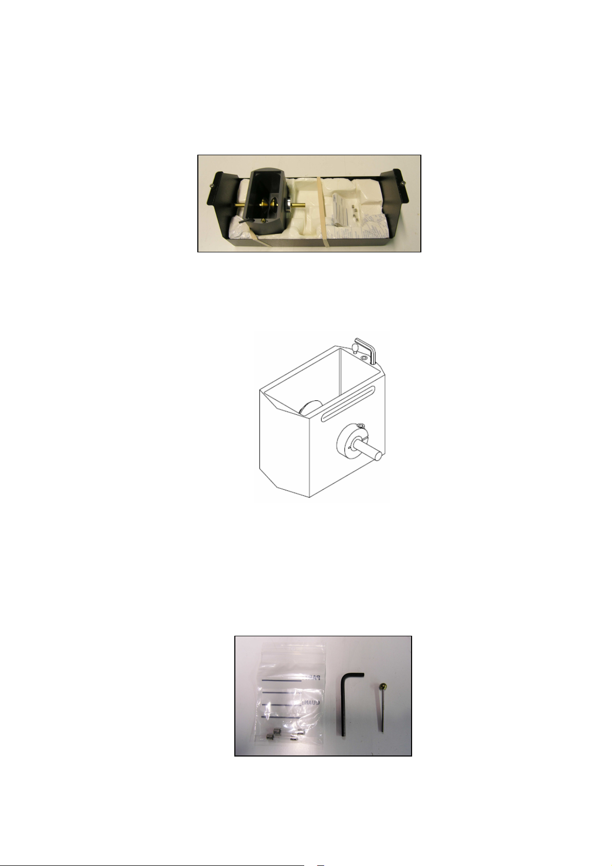
2.2. Protection Unit
Open the equipment’s door and the protection will be inside with the others
components:
2.2.1. Test Cell
Inside the protection unit it is the test cells:
2.2.2. Gauge, Allen spanner and Fuse
Look for in the protection unit where it is the bag of fuses. Allen and
gauge are in the test cell.
The delivered gauge is 2,5 mm ± 0,05 mm in width, according to the
IEC-156 standard .
Page 5

DIELECTRIC STRENGTH TESTER FOR ISOLATING OILS OT2-60D --------- Page 5
2.3. Connection cable:
It’s a standard connection cable.
3. INTRODUCTION
The OT2-60D range is automatic equipment especially designed to test the disruptive
voltage of isolating oils in new or used transformers, cables with oil, automatic
switches, capacitors, etc.
The disruptive voltage is not a basic property of the oil, but it indicates us the degree
of contamination of this oil (water, solid materials in suspension), allowing us to decide
on the possibility of carrying out a treatment of drying and filtration, or replacing the oil.
The method that the OT2-60D uses can be applied to oils of nominal viscosity of up to
350 mm2/s at 40ºC, according to IEC-156 standard.
The OT2-60D is supplied with a complete series of protectors making it highly
protected and reliable.
It is easy to handle, all buttons or illuminated switches are on the front control panel.
The test cell is especially designed to easily change the electrodes in accordance with
the different standards in operation, the easy insertion into the registering transformer
terminals and for its complete cleaning.
Page 6
DIELECTRIC STRENGTH TESTER FOR ISOLATING OILS OT2-60D --------- Page 6
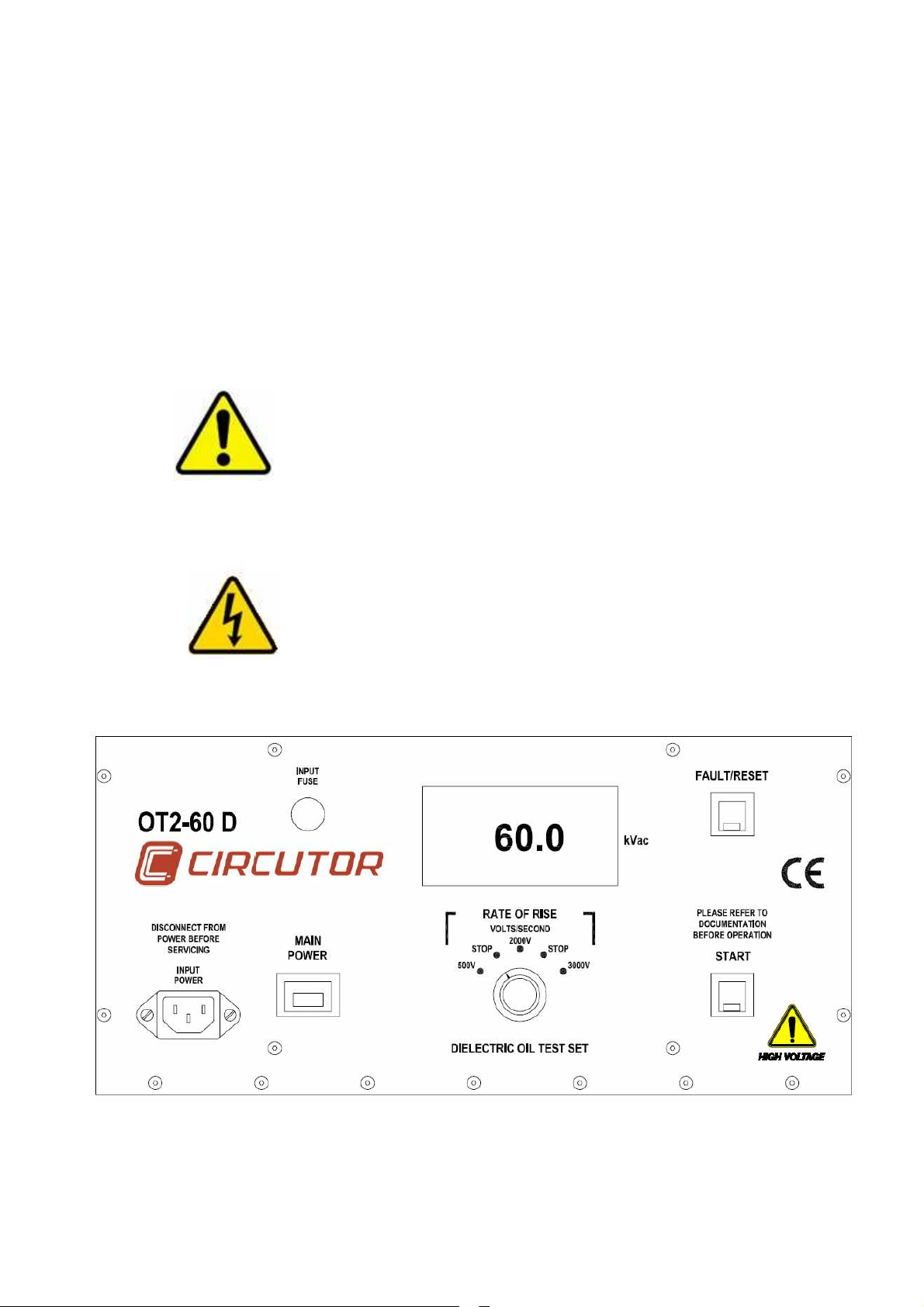
4. DESCRIPTION OF THE CONTROLS
Next we can see a representation of the controls of the equipment and the description
of its functions:
Safety Symbol Identification
Warning! Please refer to documentation before
operation
Warning! Hazardous
Voltage
Page 7

DIELECTRIC STRENGTH TESTER FOR ISOLATING OILS OT2-60D --------- Page 7
4.1. Input power
The INPUT POWER connector accepts most standard electrical equipment type
cords. The power supplied to the input connector must be from a grounded
source rated to match the input power specifications noted in Table 1.
4.2. Main power
The MAIN POWER switch provides the power to the control and power circuits.
The neon lamp will light when the power is on and voltage is available through
the input line cord. The INPUT FUSE located electrically before the MAIN
POWER switch provides line fault protection for the unit.
4.3. START
The START pushbutton activates the high voltage power circuits. The GREEN
LED indicator lamp provides long life indication of the circuit status. The LED
lights when high voltage is energized and the unit is ramping up in voltage.
4.4. Rate of rise
The RATE OF RISE output control sets the output voltage rise in three fixed
rates, 500v/2000v/3000v per second. The STOP positions between the rise
voltages allow for manual override and calibration check of the output.
4.5. KILOVOLTMETER
The digital Kilovoltmeter indicates the output voltage between the high voltage
bushings in the test chamber. The calibration accuracy is 3% of full scale. At
failure of the test sample, the meter will hold the breakdown voltage reading until
the Fault/Reset pushbutton is depressed.
4.6. Fault/reset
The FAULT/RESET pushbutton resets the hold circuits after a breakdown of the
test sample. This control can also be used to de-energize the high voltage power
circuit. The RED LED indicator lamp provides long life indication of FAULT
status. The LED lights when the output has de-activated from an arc in the test
sample. When reset, the output control must ramp back to zero before the high
voltage can be energized again.
4.7. Access interlock(not on control panel)
The Access Interlock. is provided for safety. It interlocks the access lid to the
high voltage bushings and precludes the potential for shock by requiring the
access door to be closed when high voltage is energized.
4.8. ic/iec oil vessel
This Oil Vessel is used with the OT2-60D at 2000v/SEC for testing in accord with
IEC Standard IEC-156.
Page 8

DIELECTRIC STRENGTH TESTER FOR ISOLATING OILS OT2-60D --------- Page 8
Under demand:
4.9. TC/DE oil vessel - ASTM Specification D877
This Oil Vessel is used with the OT2-60D at 3000V/SEC for testing in accord with
ASTM Specification D877. This standard can be obtained from the American
Society For Testing and Materials.
4.10. TC/VDE oil vessel - ASTM Specification D1816
This Oil Vessel and motorized stirring assembly is used with the OT2-60D at
500v/SEC for testing in accord with ASTM Specification D1816. This standard
can be obtained from the American Society For Testing and Materials.
5. PREPARATION OF THE SAMPLE
5.1.
Collection of the sample
It is very important to obtain results that adjust to the reality that you
strictly carry out the measures as it is mentioned next, otherwise, the
obtained results could be erroneous.
According to the IEC-156 standard it will be necessary to adopt the following
indications.
The oil sample will be taken in the place of the transformer, circuit breaker,
etc. where the oil is more contaminated, generally in the lowest zone of the
containers that contains it.
The amount of sample will be approximately three times superior to the
capacity of the test cell.
A topaz coloured glass bottle is the most appropriate container. The
transparent glass bottles can be used, but they must be protected of the direct
action of the light until the test is made. The plastic containers don’t have to be
attacked by the oil to test and if they are used, they cannot be reused.
In order to close the bottles, use a spiral cap, preferably of polyolefines or
polytetrafluorethylene.
The containers will be filled almost until the top, leaving approximately a 3% of
the volume of the container as free air space.
In case the container is reused, it must be cleaned (don’t forget the cap) by
means of washing with a suitable dissolvent to eliminate the rests of the last
sample. The containers will be washed finally with acetone, and the rests of
this dissolvent will be eliminated by means of hot air blown.
After the cleaning, the containers must be closed immediately and stay closed
until the moment of their use.
Page 9

DIELECTRIC STRENGTH TESTER FOR ISOLATING OILS OT2-60D --------- Page 9
5.2.
According to the IEC-156 standard it will be necessary to adopt the following
The test will be done, if another thing is not specified, with the sample as it’s
The operations of sample preparation will we done in a dry and free of dust
At the moment of the test, the temperature of the test liquid and the room
The container that contains the oil sample to test must be shacked softly and
Immediately before its use the cell will be cleaned according to 8th point.
The oil is now spilled slowly in the test cell, avoiding the formation of air
The temperature of the liquid is measured and written down.
Preparation of the sample to test
indications.
received, without drying or extracting the gas.
place.
temperature will not differ more than 5ºC and for the arbitration tests the
temperature of the oil will be between 20ºC ± 5ºC.
turned upside down several times to assure the most homogenous
distribution of the impurities contained in the oil, trying to avoid the formation
of air bubbles. Avoid the unnecessary exposing of the sample to the air of the
atmosphere.
bubbles.
It is very important for the correct development of the test that the electrodes
are totally covered by the oil, so that the distance from the surface of the oil to
the axis of the electrodes is not less than 40 mm.
6. SETTING UP THE EQUIPMENT
The setup of this equipment has been minimized by careful consideration of the
operator during design. The OT2-60D one-piece construction permits convenient
portability. The OT2-60D test set requires that the unit be operated with the control
panel in the horizontal position to keep oil over the high voltage transformer in the high
voltage tank.
6.1.
Select a location for the unit that will allow easy viewing of the kilovolt meter.
Using for it the lateral handles.
Page 10

DIELECTRIC STRENGTH TESTER FOR ISOLATING OILS OT2-60D --------- Page 10
Remarks: If it is decided to transport the equipment outside the
enclosure of habitual use, is very important that the option of FRAGILE
TRANSPORT is used.
6.2.
6.3.
6.4.
Be sure that all the controls are off, in their de-energized or fully
counterclockwise position.
Remove all components and oil vessels from the test chamber. Remember
that you have to quit the screws of transport box.
Install the input line cord into the Input Power receptacle.
6.5.
Connect the line cord to a suitable (230v, see Specification Table) grounded
power source.
CAUTION - Disconnect all power before servicing!
Page 11

DIELECTRIC STRENGTH TESTER FOR ISOLATING OILS OT2-60D --------- Page 11
6.6.
6.7.
6.8.
6.9.
Clean the Test Cell and Electrodes thoroughly and adjust the spacing of
the electrodes to conform to the proper IEC Specification. Be sure the
electrodes are securely tightened on the adjustment posts inside the oil
vessel. In order to adjust the distance between electrodes we will use the
gauge delivered with the equipment. The gauge must be placed between the
electrodes, and the distance between them will be corrected relaxing its
subjection by means of provided Allen spanner. Later it will be necessary to
tighten to maintain the required distance.
Locate sufficient insulating liquid for the testing to be performed.
Adjust the Voltimeter to zero if required.
Set the Rate of Rise to the appropriate rate for the test being performed.
The type of ramp we desire between the four possible ones, depending on the
standard we follow or depending on the indications of the oil manufacturer:
- 0.5kV/s, 2kV/s o 3kV/s.
2 kV/s is selected according to IEC-156 standard.
A note about the Oil Vessels made by Circutor.
All the oil vessels designed and made by Circutor Inc. have interchangeable posts and
electrodes. These oil vessels were designed to conform to the IEC-156 test
specifications requiring simple disassembly for cleaning. This design greatly reduces
the time and effort required keeping your oil vessels in top operating condition.
Page 12

DIELECTRIC STRENGTH TESTER FOR ISOLATING OILS OT2-60D --------- Page 12
7. OPERATING THE EQUIPMENT
There are standard tests specified (ASTM D877, ASTM D1816) for testing dielectric
oils. This manual provides step-by-step instruction on operation of the OT2-60D in
conjunction with the necessity of following the aforementioned test specifications.
Many facilities have their own in-house test standards structured around the IEC
specifications, and this manual is not to supercede these. The purpose of this section
is to explain the capabilities of this test set in real-world applications.
The test method consists of submitting the oil to an electric field from a continuously
increasing AC current until the oil is perforated because its dielectric properties are
surpassed (insulation properties). When this occurs, on the display is shown the
disruptive voltage in kV.
If we wanted to obtain the dielectric strength of the oil (kV/cm), we would have to
divide the value shown on the display (kV) by the distance between electrodes (cm). In
the case of the IEC-156 standard, this distance is 0,25 cm, therefore, if we multiply by
4 (1/0,25=4) the value shown on the display, we obtain the dielectric strength value of
the oil (kV/cm).
7.1.
7.2.
7.3.
7.4.
Ensure that setup has been accomplished as noted in Setting Up the Equipment.
After checking the Test cell for proper electrode tightness, spacing and
cleanliness, fill the selected oil vessel with sample oil to the level specified in
the IEC-156 Standard. The test sample oil temperature must be at or
below 100C to avoid damage to oil vessel.
Gently stir the oil test sample release trapped air on sides of test cup. Avoid
creating any additional air into the test solution.
Place the filled test cell onto the bushing cradle toroids. Open the door of the
equipment and place the test cell (filled with the sample of oil) inside the
chamber.
7.5.
7.6.
Close the door, since if it is not closed, the protection circuit will prevent the
operation of the equipment.
Allow the sample to stand for a minimum of three minutes. If the VDE cell
used, plug the line cord from the stirring assembly into the receptacle in the
test chamber.
Page 13

DIELECTRIC STRENGTH TESTER FOR ISOLATING OILS OT2-60D --------- Page 13
***CAUTION***
7.7.
7.8.
7.9.
7.10.
7.11.
Turn on MAIN POWER
POTENTIALLY LETHAL VOLTAGES MAY BE
PRESENT
Depress the START pushbutton to start the test. Observe the test cell as the
output ramps up at the preset rate. The voltage will rise until the sample
breaks down. At breakdown, the unit will turn off, light the Fault LED and hold
the breakdown voltage reading.
After recording the breakdown voltage, depress the Reset/Fault pushbutton.
Allow the output control to return to zero.
The cycle previously desvribed will be carried out six times with the same
sample of oil. Between the cycles it will be necessary to wait to the
disappearance of the gas bubbles that have possibly been produced, either
waiting for 5 minutes, or selecting the stirring function.
Stopping the equipment
POWER and the red Neon will be turned off.
, w
hen the equipment is not used, turn off MAIN
7.12. Evaluating the results
Once we have finished all the cycles (six), we will write down the following
data to do the report:
- Sample identification
- The value of each one of the six disruptive voltages (kV)
- The average value of the six tests (kV)
- The type of electrodes we have used and the distance between them
- The frequency of the test voltage (50 Hz)
- The oil’s temperature
- If we have used the stirrer function or not
In order to determine if the state of the oil is correct or not, we will see if the
average value of the six tests is within the right operation range that indicates
the manufacturer of the oil. If the value is outside this range we will have to
adopt the opportune measures to diminish the degree of contamination of the
oil.
If you are not able to find another value, an habitually used criterion (but not
indicated by the standard) is to consider as good the oils that have an
average value of dielectric strenght higher than 80 kV/cm (remember that we
can obtain the dielectric strenght multiplying the disruptive voltage by 4, in the
case of following the IEC-156 standard).
Page 14

DIELECTRIC STRENGTH TESTER FOR ISOLATING OILS OT2-60D --------- Page 14
8. PERFORMING SPECIAL OPERATIONS (MAINTENANCE)
The following section contains information on the care and upkeep of your new OT260D AC Dielectric Oil Test Set . There are some notes on troubleshooting and service,
which will save much time and money over the life of the unit.
8.1.
8.2.
Adjust the Voltimeter to zero if required.
The OT-60D Dielectric Oil Test Set uses precision metal film resistors for
measurement and calibration of the voltmeter. The use of these resistors has
minimized circuit drift due to aging and temperature. But, a potentiometer (R16
on the voltmeter PCB-037 can be used to correct for movement changes from
the aging of the meter.
The certification of meters on a yearly basis is recommended to ensure
accurate test results.
Other adjustments
The electrodes will be examined frequently to observe punctures or other
deteriorations and must be maintained in good state or to replace them when it
is observed that they are deteriorated (for example punctures by effect of
discharges).
The new electrodes, the pricked electrodes, and those that suitably have been
kept during a considerable time must be cleaned of the following form:
- Disassemble the electrodes of the cell using the provided Allen
- Clean all the surfaces with an appropriate volatile dissolvent and let
- Polish with an abrasive powder (for instance, red fine dust to polish)
- After polishing, clean with petroleum ether (reactive for analysis,
spanner, very carefully, avoiding to touch directly with the fingers,
very important at the end of the electrodes, in which the electrical
arc takes place.
it evaporate.
or with an abrasive paper or cloth (for instance, very fine polishing
cloth or canvas).
rank of boiling 60ºC to 80ºC), followed of acetone (reactive for
analysis).
Page 15

DIELECTRIC STRENGTH TESTER FOR ISOLATING OILS OT2-60D --------- Page 15
- Mount the electrodes in the cell, fill it with clean and new oil, of the
same type than the one that is going to test later, and elevate the
voltage until rupture 24 times.
In the case of changing the type of the test oil, eliminate all the rests of the
previous oil using a suitable dissolvent, wash the cell with the same oil that you
are going to test, drain the cell and return to fill up it to carry out the test.
During the periods of inactivity it is recommended to keep the cell full of clean
and new oil in a clean enclosure, dry and free of dust.
9. ENVIRONMENT CONSIDERATIONS
Once finalized the tests the opportune measures will be done to manage the used oil,
since this one is an injurious substance for the environment. If you don’t know how to
deal with this type of material, contact with your manager of remainders.
Page 16

DIELECTRIC STRENGTH TESTER FOR ISOLATING OILS OT2-60D --------- Page 16
10. ENVIRONMENT CONSIDERATIONS
The OT2-60D AC Dielectric Oil Test Set provides repeatable, accurate measurement
of breakdown voltage of insulating oils used in electrical equipment. The OT2-60D can
also be setup as a voltage source for an external vacuum bottle or chamber by the use
of two shielded output cables which mate to the oil cup cradle electrodes.
Standard features of the OT2-60D of AC Dielectric Oil Test Set:
- Three Fixed rates of rise, 500V/2000V/3000V per second
- Arc detection with 30 millisecond shutdown
- “Zero Start” and Access Interlock provision
- Primary connected 3.5 digit LED voltmeter display
- One piece portable design (cables and oil vessels store in the control
case).
- Rugged aluminum case
- Window for observation of oil test (special window required for use of
cables)
- Stop/Dwell rate of rise positions
- Simple controls
Page 17

DIELECTRIC STRENGTH TESTER FOR ISOLATING OILS OT2-60D --------- Page 17
MODEL SPECIFICATIONS AND OPERATING ENVIRONMENT
Input
Output
Output Termination
Oil Test Cells
Available
Oil Test Cells
Under demand
Operating
Temperature
Distortion
Meter Accuracy
Kilovoltmeter
Dimensions
OT2-60D
230 V ± 10 % , 50/60 Hz, 3 A, single fase.
0-60kVac, 800VA resistive load, between bushings.
Dual Capacitively Graded Bushings.
IEC 156
ASTM D1816, ASTM D877
5°C a 40°C
<5%
2% Full Scale.
3.5 digit LED Escalado 0-60.0 kV AC (RMS)
380mm wide x 360mm deep x 295mm high
Weight
Altitude
(27kg)
100% of rating; Sea-level, up to 1500M. The maximum output
voltage is de-rated 5% above 1500M altitude, 10% above
3600M, and 15% above 4500M.
Storage Temperature
Operating
-10°C to 60°C, (14°F to 140°F).
5°C to 40°C (40°F to 104°F).
Temperature
Maximum Relative
Humidity
Installation
Pollution
80% up to 31°C(88°F), decreasing linearly to 50% at 40°C(104°F)
Category II
Degree 2
Table OT2-60D specifications
Page 18

DIELECTRIC STRENGTH TESTER FOR ISOLATING OILS OT2-60D --------- Page 18
11. WARNINGS
11.1.
11.2.
11.3.
11.4.
If the equipment detects any form of anomaly, the "ALARM" light will come on
and a continuous alarm will sound. In this event the equipment has to be
stopped with the key. Your distributor has to be consulted if this occurs.
If the front cover is opened, the equipment and the active earthed parts will not
operate.
IT IS NOT RECOMMENDED TO USE THE EQUIPMENT WITHOUT THE
TEST CELL AND WITHOUT OIL IN THE CELL.
UNDER NO CIRCUMSTANCES SHOULD THE EQUIPMENT BE OPENED,
HANDLED OR USED IN WAYS OTHER THAN THOSE INDICATED IN THIS
MANUAL. IN THIS EVENT THE GUARANTEE WILL BE NULLIFIED. THE
COMPANY IS NOT RESPONSIBLE FOR DAMAGE TO GOODS OR
PERSONS RESULTING FROM MISHANDLING.
 Loading...