

Page 1
Low voltage capacitor banks switched by
contactors.
OPTIM P&P Series
INSTRUCTION MANUAL
(M063B01-03-15A)
Page 2

OPTIM P&P Series
2
Instruction Manual
Page 3
OPTIM P&P Series
SAFETY PRECAUTIONS
Follow the warnings described in this manual with the symbols shown below.
DANGER
Warns of a risk, which could result in personal injury or material damage.
ATTENTION
Indicates that special attention should be paid to a speci c point.
If you must handle the unit for its installation, start-up or maintenance, the following
should be taken into consideration:
Incorrect handling or installation of the unit may result in injury to personnel as well as damage
to the unit. In particular, handling with voltages applied may result in electric shock, which may
cause death or serious injury to personnel. Defective installation or maintenance may also
lead to the risk of re.
Read the manual carefully prior to connecting the unit. Follow all installation and maintenance
instructions throughout the unit’s working life. Pay special attention to the installation standards of the National Electrical Code.
Refer to the instruction manual before using the unit
In this manual, if the instructions marked with this symbol are not respected or carried out correctly, it can
result in injury or damage to the unit and /or installations.
CIRCUTOR, SA reserves the right to modify features or the product manual without prior noti cation.
DISCLAIMER
CIRCUTOR, SA reserves the right to make modi cations to the device or the unit speci ca-
tions set out in this instruction manual without prior notice.
CIRCUTOR, SA on its web site, supplies its customers with the latest versions of the device
speci cations and the most updated manuals.
www.circutor.com
Instruction Manual
3
Page 4

OPTIM P&P Series
CONTENTS
SAFETY PRECAUTIONS .......................................................................................................................................3
DISCLAIMER ..........................................................................................................................................................3
CONTENTS ............................................................................................................................................................. 4
REVISION LOG .......................................................................................................................................................5
1.- VERIFICATION UPON RECEPTION ................................................................................................................. 6
1.1.- RECEPTION PROTOCOL .......................................................................................................................... 6
1.2.- TRANSPORT AND HANDLING .................................................................................................................6
1.3.- STORAGE...................................................................................................................................................7
2.- PRODUCT DESCRIPTION ................................................................................................................................ 8
3.- INSTALLATION .................................................................................................................................................8
3.1.- PRELIMINARY RECOMMENDATIONS .....................................................................................................8
3.2.- PREPARATION ...........................................................................................................................................9
3.3.- INSTALLATION LOCATION ..................................................................................................................... 10
3.4.-CONNECTION OF THE CAPACITOR BANK TO THE MAINS ................................................................. 10
3.5.-POWER CIRCUIT ...................................................................................................................................... 11
3.6.- EXTERNAL CIRCUIT BREAKER AND PROTECTION ELEMENTS .......................................................11
3.7.- AUXILIARY CONTROL VOLTAGE ...........................................................................................................11
3.7.1. CAPACITOR BANK WITH AUXILIARY VOLTAGE OBTAINED FROM AN INTERNAL AUTO-
TRANSFORMER ..........................................................................................................................................12
3.7.2. CAPACITOR BANK WITH AUXILIARY VOLTAGE OBTAINED BETWEEN PHASE-NEUTRAL......12
3.8.- EARTH CABLE CONNECTION ...............................................................................................................13
3.9.- CURRENT TRANSFORMER (CT) CONNECTION .................................................................................13
4.- CAPACITOR BANK START-UP ..................................................................................................................... 15
4.1.- BEFORE START-UP .................................................................................................................................15
4.2.- START-UP .................................................................................................................................................15
4.3.- CHECKS ONCE THE CAPACITOR BANK HAS BEEN CONNECTED AND THE REGULATOR ......... 17
5.- MAINTENANCE ............................................................................................................................................... 18
5.1.- SAFETY REGULATIONS ......................................................................................................................... 18
5.2.- MAINTENANCE WITH THE CAPACITOR BANK DISCONNECTED ...................................................... 18
5.2.1. BASIC MAINTENANCE PROTOCOL ................................................................................................18
5.2.2. TIGHTENING TORQUE OF THE ELECTRICAL CONNECTIONS ..................................................... 19
5.2.3. KEY POINTS FOR INSPECTING CONTACTORS ............................................................................. 19
5.2.4. KEY POINTS FOR INSPECTING CAPACITORS ............................................................................... 20
5.2.5. KEY POINTS FOR INSPECTING THE REGULATOR ....................................................................... 20
5.2.6. CLEANING THE CABINET ................................................................................................................21
5.3.- MAINTENANCE WITH THE CAPACITOR BANK CONNECTED ........................................................... 21
5.3.1. REGULATOR CHECKS ...................................................................................................................... 22
5.4.- ENVIRONMENTAL CONDITIONS ............................................................................................................ 22
6.- TECHNICAL FEATURES ................................................................................................................................ 23
7.- STANDARD ELECTRICAL DIAGRAMS ......................................................................................................... 24
8.- MAINTENANCE AND TECHNICAL SERVICE ................................................................................................ 33
9.- GUARANTEE ...................................................................................................................................................33
10.- CE CERTIFICATE .......................................................................................................................................... 34
4
Instruction Manual
Page 5

OPTIM P&P Series
REVISION LOG
Table 1: Revision log.
Date Revision Description
02/15 M063B01-03-15A Initial Version
Note: The images of the units are solely for the purpose of illustration and may differ from the
original unit.
Instruction Manual
5
Page 6
OPTIM P&P Series
1.- VERIFICATION UPON RECEPTION
1.1.- RECEPTION PROTOCOL
Check the following points when you receive the unit:
a) The unit meets the specications described in your order.
b) The unit has not suffered any damage during transport.
c) Perform an external visual inspection of the unit prior to switching it on.
d) Check that it has been delivered with the following:
- The unit manual
- The installed regulator manual.
If any problem is noticed upon reception, immediately contact the transport
company and/or CIRCUTOR's after-sales service.
1.2.- TRANSPORT AND HANDLING
The transport, loading and unloading and handling of the unit must be carried
out with proper precautions and using the proper manual and mechanical
tools so as not to damage it.
If the unit is not to be immediately installed, it must be stored at a location
with a rm and level oor, and the storage conditions listed in the technical
features section must be observed. In this case, it is recommended that the
unit be stored with its original protective packaging.
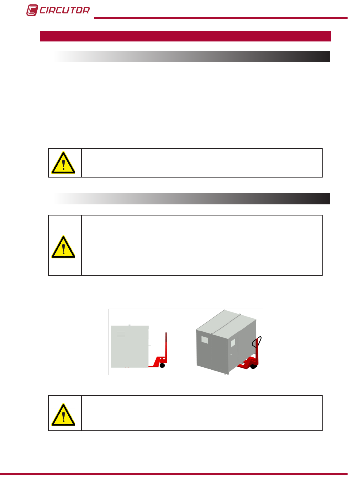
To move the unit a short distance, the unit's oor support proles facilitate handling with a pallet
jack or forklift. (Figure 1)
Figure 1: Transport with pallet jack.
The centre of gravity of some units may be found at a considerable height.
Therefore, when handling with a forklift, it is recommended that the unit be
securely fastened and that no abrupt manoeuvres made. The unit should not
be lifted more than 20 cm off the ground
6
Instruction Manual
Page 7
OPTIM P&P Series
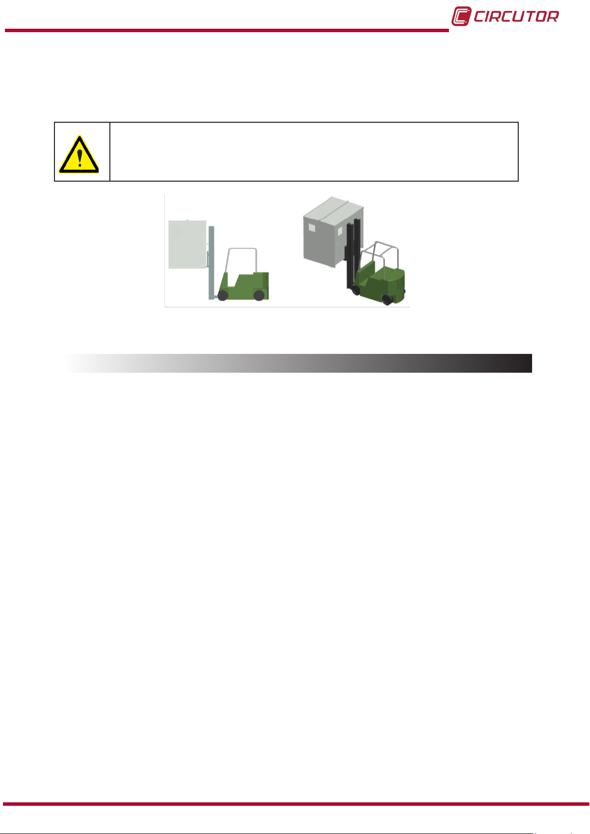
When unloading and moving the unit, use a forklift with forks long enough to support the entire
length of the base. Otherwise, the forks should be long enough to support at least ¾ of said
depth. The forks must be at and supported rmly by the base. Raise the cabinet by placing the
forks underneath the prole that supports the unit. (Figure 2).
There might be an offset in the centre of gravity from the centre of the cabinet,
as a result of the uneven distribution of loads inside the unit. The necessary
precautions must be taken to prevent the unit from tipping over during abrupt
operations.
Figure 2: Unloading with a forklift.
1.3.- STORAGE
The following storage recommendations must be followed for the hybrid capacitor banks:
Avoid placing them on uneven surfaces.
Do not store them in outdoor areas, humid areas or areas exposed to splashing
water.
Avoid hot spots (maximum ambient temperature: 40 ºC)
Avoid salty and corrosive environments.
Avoid storing the units in areas where a lot of dust is generated or where the risk of
chemical or other types of contamination is present.
Do not place any weight on top of the unit cabinets.
Instruction Manual
7
Page 8

OPTIM P&P Series
2.- PRODUCT DESCRIPTION
The purpose of this manual is to assist during the installation, start-up and maintenance of
OPTIM P&P series low voltage (LV) capacitor banks switched by contactors. Carefully read the
manual to achieve the best performance from those units.
3.- INSTALLATION
3.1.- PRELIMINARY RECOMMENDATIONS
In order to use the unit safely, it is critical that individuals who handle it follow the
safety measures set out in the standards of the country where it is being used,
use the personal protective equipment necessary, and pay attention to the various warnings indicated in this instruction manual.
Installation or maintenance personnel should read and understand this manual
before operating the unit.
A copy of this manual should always be available to maintenance personnel for
reference purposes
Connecting the unit to the public mains must be carried out in compliance with
the EN-IEC60204-1 standard, regarding the safety of LV electrical installations.
It is recommended that several personnel are present when handling the unit for
installation or maintenance.
If damage or faults are detected during unit operation, or in circumstances that
compromise safety, immediately stop work in that area and disconnect the unit in
order to check it without voltage.
The manufacturer of the unit is not responsible for any damage resulting from failure by the
user or installer to heed the warnings and/or recommendations set out in this manual, nor for
damage resulting from the use of products or accessories that did not come with the unit or that
were made by other manufacturers.
If an anomaly or malfunction is detected in the unit, do not use it to perform any operation.
Modifying, upgrading or rebuilding the unit without written authorisation from the
manufacturer is prohibited.
The installation, operation and maintenance of low voltage (LV) units must only
be carried out by authorised installers. LV regulations (Art. 22) specically dene
the requirements that authorised installers must meet.
8
Instruction Manual
Page 9

OPTIM P&P Series
Do not access the active elements of a capacitor bank with static operation that
has been powered and might have voltages present. Wait at least 5 minutes after the power supply has been disconnected.
Do not touch the terminals or active parts of the unit until you have veried that
voltage is not present. If you have to handle or touch the terminals or other control
panel components, use adequately insulated personal protection equipment and
tools.
After any maintenance and before re-connecting the power supply to the unit,
check that its enclosure is properly closed and that no items or tools were left
inside that could cause a short-circuit.
Do not disconnect the current transformer secondary without short-circuiting it
rst. The operation of a current transformer with an open secondary will cause an
overvoltage that could damage it and electrocute the person handling it.
3.2.- PREPARATION
The CIRCUTOR OPTIM P&P static capacitor banks come ready for easy installation and startup.
Remove the packaging of the unit and verify that its electrical features are suitable for connection to the available mains. To do so, check the features label located inside the cabinet next to
the FP regulator, see Figure 3.
Key data to be checked:
Mains frequency and voltage, Un / fn.
Nominal power of the capacitor bank, Qn (kvar) and composition
Current consumption, In . This current must be considered to select the proper size
of the power supply cable of the unit and ultimately the circuit breakers and protection
elements to be connected in front of it.
Auxiliary control voltage, U
.( See “3.7.- AUXILIARY CONTROL VOLTAGE”)
aux
Environmental conditions. (See “6.- TECHNICAL FEATURES”)
Instruction Manual
Figure 3: Features label.
9
Page 10
OPTIM P&P Series
3.3.- INSTALLATION LOCATION
It is important to maintain a minimum distance around the unit to facilitate cooling.
In self-supporting cabinets, the back and front sides of the cabinet must be kept at least 50 cm
away from walls of other units and other infrastructure to allow for ventilation.
In terms of the side walls, it is recommended that a separation of 10 cm be maintained between
adjacent cabinets.
On wall-mounted cabinets, it is recommended that at least 20 cm of separation be maintained
between the sides of adjacent cabinets.
Make sure the unit can be accessed easily.
The environmental conditions of the location where the unit is installed must not exceed the
limits set forth in the technical features (See “6.- TECHNICAL FEATURES”)
To ensure proper ventilation, the unit must be installed in a vertical position.
In accordance with the LVR, once the unit is installed, it must be protected against direct and indirect contacts; therefore, a circuit breaker and earth leakage protection for the capacitor bank
power supply line should be installed.
3.4.-CONNECTION OF THE CAPACITOR BANK TO THE MAINS
Check that the rated voltage of the capacitor bank matches the voltage between
phases of the network to which it is being connected.
Also check the operating circuit voltage (contactors).
( See “3.7.- AUXILIARY CONTROL VOLTAGE”)
For feeding cables into the capacitor bank cabinet, always and only use the cable
entry points available for this purpose.
There is a cable entry point on the bottom (base of the cabinet) in all the models
and also an entry point on the side in some models.
If another part of the cabinet is cut out to be used for cable entry, the CIRCUTOR manufacturer's guarantee shall be rendered void.
10
Do not cut holes in other parts of the cabinet for feeding cables through or for
installing support brackets.
It may produce trimmings that can cause short-circuits.
Instruction Manual
Page 11
OPTIM P&P Series
3.5.-POWER CIRCUIT
Connect input terminals L1, L2 and L3 (power circuit) to the mains using proper sized cable in
accordance with the LVR, ITC-BT-19.
Generally, the cables of the phases adhere to the following colour code: L1 (black), L2 (brown),
L3 (grey).
If auxiliary voltage is required, the neutral cable will be connected to N (blue colour)
In order to determine the size of the phase cables, the nominal current In must be taken into
account, indicated on the unit label, and it should be able to withstand an overload in transients
of 1.5 times In. The neutral cable will be a minimum of 1.5 mm2.
3.6.- EXTERNAL CIRCUIT BREAKER AND PROTECTION ELEMENTS
If the capacitor bank does not have an internal switch or isolation switch, it must be connected
to a line that has an external switch or isolation switch.
The protection elements, isolation switches and/or switches that are added externally to the capacitor bank must be of a minimum size to withstand a current 1.5
times greater than what is indicated on the label (LVR, ICT-BT-48)
If an earth leakage protection for the capacitor bank is installed, its sensitivity and
trip delay must be adjustable.
When the capacitor bank is connected to the mains, it is recommended that the current
transformer (CT) is placed on the phase going to L1 (black cable).
Outputs S1 and S2 of the CT must be connected to the terminals with the same name.
3.7.- AUXILIARY CONTROL VOLTAGE
Control circuits are dened as those related with regulator output relays and the capacitor's
operating contactors. These circuits are usually powered with an auxiliary voltage of 230 V
~ (the most common case) or other voltages such as 110 V ~ (frequently for 500 V or 690 V
capacitor banks).
There are two possible ways of powering the circuit:
Instruction Manual
11
Page 12
OPTIM P&P Series
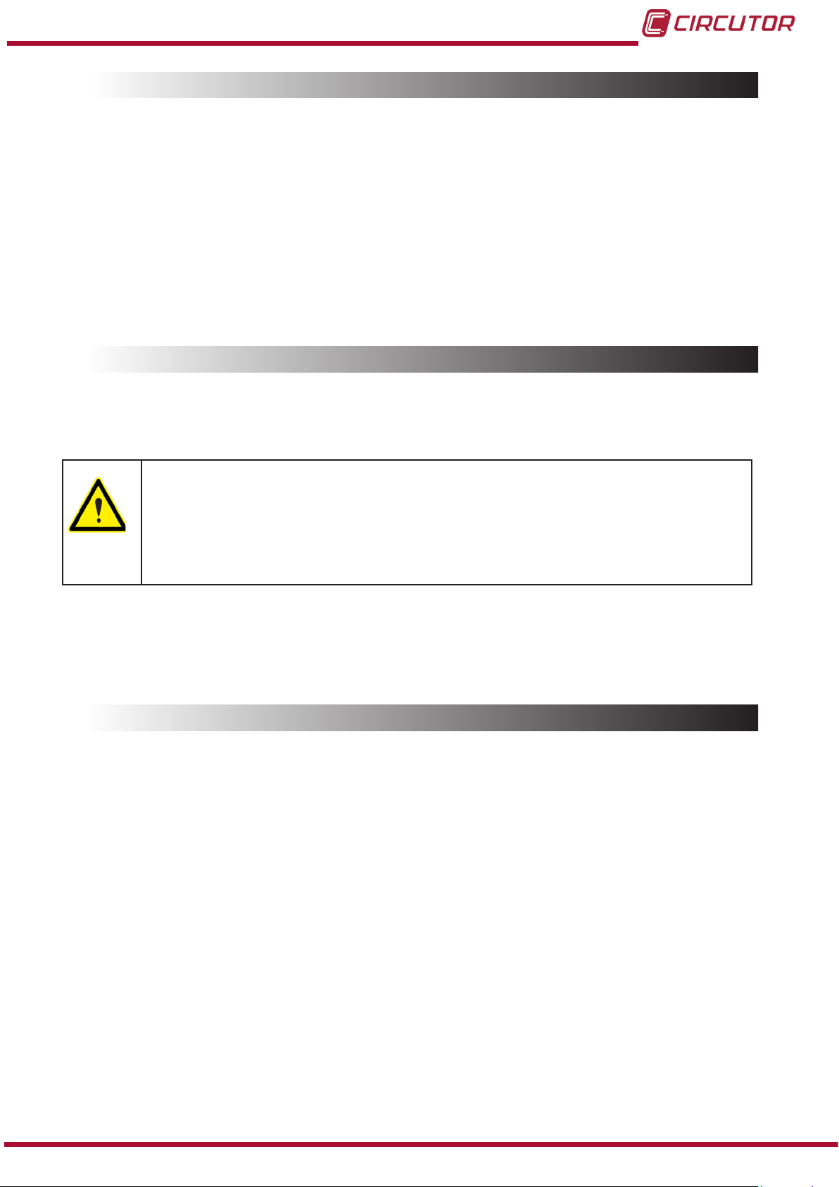
3.7.1. CAPACITOR BANK WITH AUXILIARY VOLTAGE OBTAINED FROM AN INTERNAL AUTOTRANSFORMER
Does not require connection of the external neutral. The label indicates U
Figure 4: Auxiliary power supply with autotransformer.
/f … internal
aux
3.7.2. CAPACITOR BANK WITH AUXILIARY VOLTAGE OBTAINED BETWEEN PHASE-NEUTRAL
Requires the connection of the external neutral to terminal N (see Figure 5 and Figure 7 )
The label indicates Uaux/f … (control voltage)
Figure 5: Auxiliary power supply with neutral.
12
Instruction Manual
Page 13
OPTIM P&P Series
3.8.- EARTH CABLE CONNECTION
Connect the earth cable to the capacitor bank's earth terminal located on the operating panel
of the unit.
The earth cable cross-section will be selected in accordance with the admissible current limits
established in the LVR (ITC-BT-19 – Internal or receiver installations) for each type of cable and
their location.
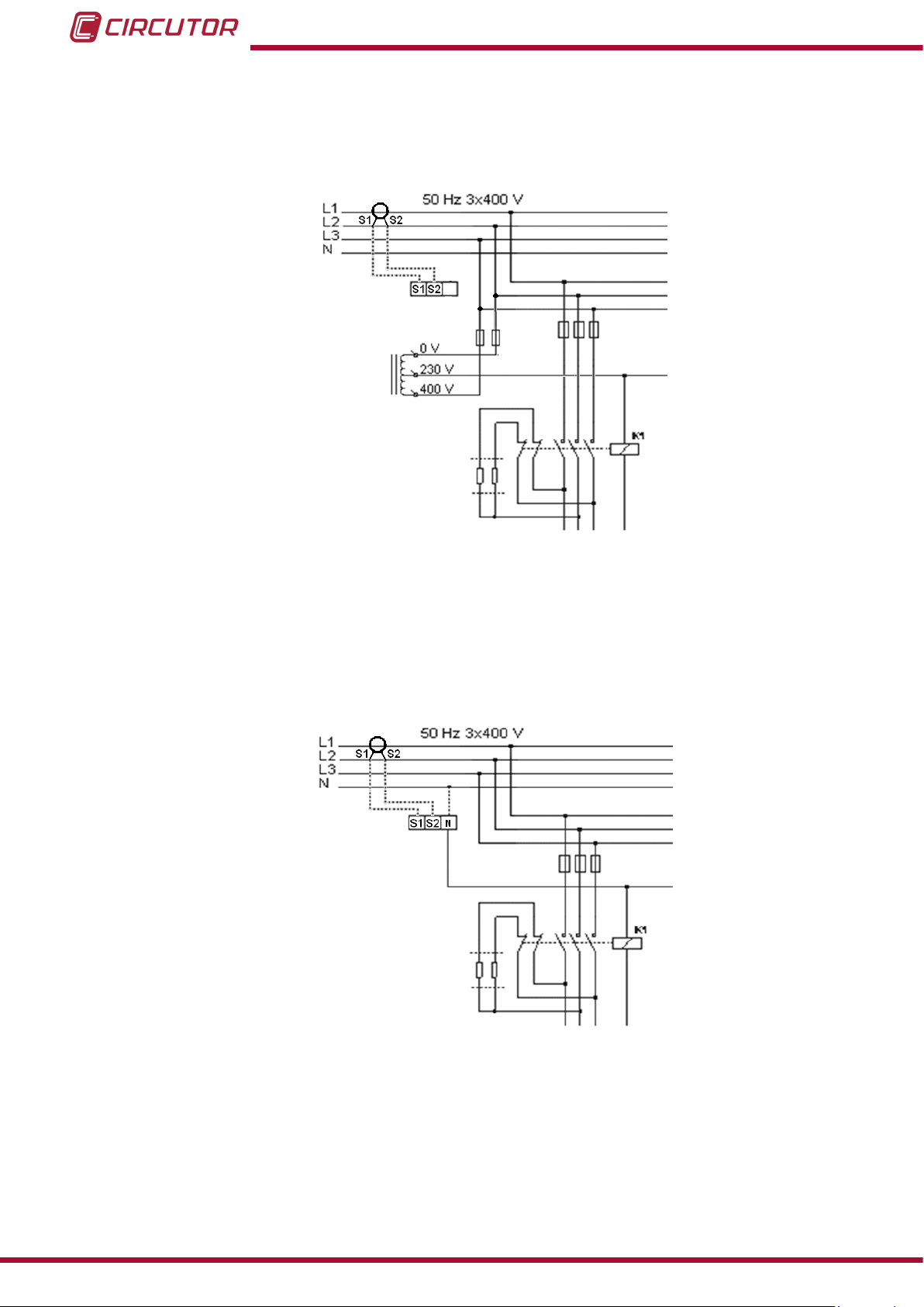
3.9.- CURRENT TRANSFORMER (CT) CONNECTION
A current transformer (CT) that is external to the capacitor bank must be
installed to measure the total load current plus that of the capacitor bank
(Figure 6).
The standard transformer must have a nominal output of 5 A at the secondary.
We recommend connecting the CT to phase L1 in the direction of the current ow
from P1 to P2 (see Figure 6) and connecting the secondary (terminals S1, S2) to
the terminals with the same name on the capacitor bank (see Figure 6)
Avoid current ow through the CT primary winding prior to connecting it to terminals S1 S2 of the bank.
If the CT must be installed while the installation is under load, short-circuit S1 and
S2 while they are not connected to the capacitor bank.
The current value of the CT primary winding must be equal to or slightly greater than the size of
the mains switch of the installation. Therefore, the CT must be able to measure the maximum
current expected to be consumed by all the loads being compensated.
Figure 6: Installation of the external current transformer (CT).
The connection point of the CT for a capacitor bank that compensates an entire installation is
after the mains switch of the installation.
To prevent excessive attenuation of the signal, it is recommended that the minimum cross-section of the secondary section winding cable (terminals S1, S2) is at least 2.5 mm2.
Instruction Manual
13
Page 14

OPTIM P&P Series
Figure 7: Current transformer (CT) and neutral connection terminals (if required).
Once the cables are installed, disconnect the jumper connecting the S1 and S2 terminals or the
yellow jumper according to the terminals of the capacitor bank (Figure 8)
Figure 8: Jumper for short-circuiting the secondary winding of the current transformer (CT).
Any time you wish to change or disconnect a current transformer that is already
installed, it is important to install the jumper connecting S1 and S2.
14
Instruction Manual
Page 15

OPTIM P&P Series
4.- CAPACITOR BANK START-UP
4.1.- BEFORE START-UP
The automatic capacitor banks include a power factor regulator.
The operation of said regulator must be known prior to start-up; for this reason, all
the capacitor banks include a specic manual for the regulator used.
Ensure you have this manual available for the start-up process.
In order to adjust the regulator incorporated to the capacitor bank and for optimum start-up, the installation load must be at least 30% or 40% of the nominal
load for which the capacitor bank has been dimensioned. If all the stages are not
included, they can be manually connected to check them all.
During low load periods, the entire capacitor bank should not be connected manually, as in some cases resonance with the power transformer of the installation
could occur.
The capacitors are connected in manual mode, rst allow enough time for the capacitors to discharge (as indicated in the capacitor bank's features label) before
reconnecting them to the network.
Otherwise, they could start-up out of phase with a voltage of up to 2xUn causing
the destruction of the capacitor.
4.2.- START-UP
Apply the safety regulations listed in section “3.- INSTALLATION” of this manual
before operating the units.
The National Electric Code of the country where the capacitor bank is installed or operated should be strictly followed.
1.- Ensure that the inner circuit breaker that starts the regulator (Figure 11) is connected.
2.- Connect the power supply to the panel and check that the regulator display illuminates im-
mediately. Otherwise, stop and check the previous step.
3.- Check the regulator's cos φ indication.
If the indication is out of range 0.5 to 1, it may be possible that the current transformer and/or
the power supply to the regulator are not properly connected.
Most of the regulators use only one current transformer. In this case, connect according to
Figure 10 (place the current transformer on phase L1 and take the power supply voltage from
phases L2 and L3).
Instruction Manual
15
Page 16

OPTIM P&P Series
Figure 9: Plug&Play Computer Max Regulator. (Photo as an example, it may not coincide with the model used on
your unit).
POWER
SUPPLY
400 V ac
L1
L2
L3
N
A B
S1 S2
P1 P2
1 2
-
- + C1 ... C6
5
3
6
4
C D
0
Figure 10: Connection of a regulator with only one CT. (If using Computer SMART III or Computer Plus, 3 CT are
used. Check the specic manual. )
16
Figure 11: Two-pole circuit breaker for the auxiliary power circuit.
4.- Once ensured that the regulator is properly connected, adjust the regulator parameters for
the installation you are attempting to compensate. For this, follow the instructions on the manual of the regulator, included with the capacitor bank.
Instruction Manual
Page 17

OPTIM P&P Series
4.3.- CHECKS ONCE THE CAPACITOR BANK HAS BEEN CONNECTED AND THE REGULATOR
1.- After start-up, make sure that the unit is operating correctly. A sign of proper operation is the
display indicating a cos φ close to 1 and the reactive energy meter should stop (if it is electromechanical) or the blinking light of the indicator LED of the kvar.h/pulse ratio should reduce its
rate.
2.- Check that the power supply voltage does not exceed the nominal value +10%
(IEC 60831-1).
3.- Check the current absorbed by each capacitor.
Under normal conditions, it must be close to the nominal value indicated on its dataplate and
never exceed 1.3 times this value constantly.
Continuous consumption over the nominal value may be caused by the presence of harmonics
in the network or an excessively high power supply voltage. Both circumstances are harmful
for capacitors.
4.- In accordance with the IEC 60831-1 Standard, the capacitor is prepared to operate at the
permanent voltage assigned to it and with an overvoltage of up to 10% for 8 out of every 24
hours.
Check the working temperature of the capacitors after they have been operating
for 24 hours.
The housing must be below 40 ºC.
Instruction Manual
17
Page 18

5.- MAINTENANCE
5.1.- SAFETY REGULATIONS
Take the safety regulations listed in section of this manual into account before
operating the units “3.1.- PRELIMINARY RECOMMENDATIONS”
The National Electric Code of the country where the capacitor bank is installed or
operated should be strictly followed.
5.2.- MAINTENANCE WITH THE CAPACITOR BANK DISCONNECTED
5.2.1. BASIC MAINTENANCE PROTOCOL
Monthly:
Visually inspect the capacitors.
OPTIM P&P Series
Check the protection fuse.
Control the ambient temperature (average of 35 ºC. In accordance with IEC 60831 ).
Control the service voltage (especially during moments of low load, it must not exceed
the nominal +10%).
Bi-annually:
Keep the capacitor terminals clean.
Verify the state of the contacts of operating elements.
Check that the capacitor current is not lower than 25% nor greater than 120% of the
nominal value by phase and that there is no phase unbalance greater than 15%.
Annually:
Carry out a dielectric rigidity test by applying 2.5 kV for 1 second between the terminals
of the capacitor and earth.
Check the capacity of the capacitors at the different steps.
One indirect check may be to check that the consumption is manual.
Check the tightness of all terminal connections.
18
Inspect the fuses.
- Power Circuit: NH fuses. Check continuity and temperature.
- Power Circuit: Check the continuity and temperature of the three-pole or four-pole
circuit breaker.
- Control Circuit: Check the continuity and temperature of the two-pole circuit breaker.
Instruction Manual
Page 19

OPTIM P&P Series
5.2.2. TIGHTENING TORQUE OF THE ELECTRICAL CONNECTIONS
The connections must be tight.
The tightening torques for the fuse bases, circuit breakers and the contactors are indicated in
Table 3 , Table 4 and Table 4.
Table 2:Tightening torques of the cables to the fuse bases.
Fuse base Torque (Nm)
NH-00 15.2
Table 3:Torques of power cables to two-pole and three-pole circuit breakers.
Circuit breaker Torque (Nm)
In ≤ 3 x 63 A 2
In ≤ 2 x 6 A 2
Table 4:Torques of cables to connector terminals
Model Auxiliary (Nm) Power (Nm)
CMC-12 1.3 1.6
CMC-18 1.3 2.2
CMC-32 1.3 2.9
CMC-40 1.3 2.9
CMC-50 1.3 4.5
CMC-65 1.3 4.5
CMC-75 1.3 4.5
CMC-85 1.3 5.1
CMC-150 1.3 9
5.2.3. KEY POINTS FOR INSPECTING CONTACTORS
Check that the plastic parts are not blackened and do not show signs of burning or hardening.
Check that the head is properly inserted.
Check the tightness of cables and terminals, as shown in Table 4.
The terminals must be clean.
If the capacitor bank includes RD discharge resistors, check they are in good condition (that
they are not open or show signs of burning). (Figure 12)
Instruction Manual
19
Page 20

OPTIM P&P Series
RD
Figure 12: Connection of the discharge resistors.
K1
Cleaning the contactors: In dirty environments (dust, sawdust, rust particles, etc.) vacuum
the contactor periodically.
There is no estimated time frame for cleaning, it depends on the amount of dirt that is inside the
capacitor bank.
5.2.4. KEY POINTS FOR INSPECTING CAPACITORS
Inspect the cables and terminals. They should not be overheated or blackened.
The terminals must be clean.
The slow discharge resistors must be in good condition. They must not be open or show
signs of burning.
Check the tightness of the capacitor terminals, as shown in Table 5.
Table 5:Torques of the cables to the capacitor terminals.
Cylindrical capacitor Power terminal torque (Nm)
CLZ FP 2
Prismatic capacitor
CV 4.49 6.2
CSB 21 6.2
Torque
Power terminal (Nm)
Earth terminal (Nm)
Torque
5.2.5. KEY POINTS FOR INSPECTING THE REGULATOR
Check that the regulator does not show signs of deterioration and the display is lit as normal.
Inspect the cables and terminals. They should be clean and should not be hardened or over-
heated.
20
Inspect the connections and the insertion of removable power strips:
- The power strips must be well fastened on removable regulators.
- Check that the terminals are tightened properly. The recommended torque is 0.6 Nm.
Instruction Manual
Page 21

OPTIM P&P Series
5.2.6. CLEANING THE CABINET
Remove possible metallic and non-metallic particles.
Clean the inside of the cabinet.
Clean ventilation grilles.
5.3.- MAINTENANCE WITH THE CAPACITOR BANK CONNECTED
Check that the main switch turns on and off without having to force the mechanism.
If there is an individual earth leakage protection for the capacitor bank, check its proper
operation by pressing the test button.
Check that the auxiliary control voltage is within the tolerance limits.
If the capacitor bank has an autotransformer, check that it is in good condition and shows no
signs of deterioration.
Force the connection and disconnection of the capacitors in manual mode. (refer to the reg-
ulator's manual before carrying out these actions) and perform the following checks:
- Check that the contactors connect and disconnect properly.
- Check that the contactor, once connected, does not rattle or vibrate.
- Check the consumption of the capacitors in each of the phases.
The nominal values are shown in Table 6.
.
Table 6:Nominal consumption of the capacitor paths, by power and voltage.
Power
3 x 230V ~
2.5 kvar 6.28 A
5 kvar 12.56 A
7.5 kvar 18.85 A
10 kvar 25.12 A
12.5 kvar 31.41 A
15 kvar 37.7 A
20 kvar 50.24 A
25 kvar 62.82 A
30 kvar 75.4 A
40 kvar 100.48 A
50 kvar 60 kvar 80 kvar -
In, Current
3 x 400V~
3.6 A
7.2 A
10.8 A
14.4 A
18 A
21.6 A
28.8 A
36 A
43.2 A
57.6 A
72 A
86.4 A
115 A
Note: If consumption is ±25% less than that indicated in Table 6 and the voltage is within the
tolerance limits, this is usually a sign of degradation of the capacitors. If this is detected in any
capacitor, it should be replaced with another capacitor.
Instruction Manual
21
Page 22

OPTIM P&P Series
5.3.1. REGULATOR CHECKS
Refer to the manual of the specic regulator used in the capacitor bank.
This manual is always supplied with the capacitor bank
Check that there are no faulty segments on the display.
Check that the keyboard is operating properly:
- Enter Setup and check the adjusted values
- Force the manual connection and disconnection of a step.
5.4.- ENVIRONMENTAL CONDITIONS
Check that the maximum environmental conditions listed in section “6.- TECHNICAL FEA-
TURES” are being observed.
22
Instruction Manual
Page 23

OPTIM P&P Series
6.- TECHNICAL FEATURES
Electrical features
Usage voltage and nominal frequency Un / fn, listed on the label
Design voltage Un+ 10% (440 V for 400 V units)
Nominal power and distribution of steps Qn and composition, (see label)
Total losses < 0.5 W / kvar
Residual discharge voltage 75 V after 3 minutes
Overload capacity 1.3 In in all the elements
Contactor operating voltage Uaux, marked on the label
Current Transformer Secondary winding 5 A, (Transformer In/5 A)
NOTE: Minimum cable section of 2.5 mm2.
(1)
For standard OPTIM 3 P&P and OPTIM 5 P&P models, supply external voltage with a 1.5 mm
cable.
If “Internal” is marked, this circuit does not require power.
For the rest of the models, an autotransformer is already included for auxiliary power supply, so no
external auxiliary power supply is required.
Capacitor features
Capacity tolerance - 5% / + 10%
Insulation level from earth 3 kV /50 Hz
Impulse test 15 kV, ray-type wave 1.2/50 µs
Protections Internal fuses and over-pressure system
In accordance with Standards UNE EN 60831
(1)
2
Environmental features
Category D in accordance with EN 60831-1
Maximum temperature of capacitors
Maximum during 1 h. 24 h average Annual mean
55 ºC 45 ºC 35 ºC
Cabinet ventilation
For outdoor Tamb > 30 ºC forced ventilation should be provided in the cabinet
Maximum relative humidity 80%
Maximum altitude 1000 m
(For higher altitude, forced ventilation should always be
provided)
Protection degree Marked on the label
Mechanical features
Model OPTIM 3 P&P OPTIM 5 P&P OPTIM 9 P&P
Dimensions (Width x Height
(2)
x Depth) 400x600x260 mm 600x740x260 mm 700x1350x440 mm
Weight 40 Kg 55 Kg 134 Kg
Model OPTIM 8 P&P OPTIM SC8 P&P OPTIM SC12 P&P
Dimensions (Width x Height
(2)
x Depth)
1000x1750x440 mm 1180x1340x460 mm 1930x1895x460 mm
Weight 265 Kg 155 Kg 595 Kg
Model OPTIM SC16 P&P
Dimensions (Width x Height
(2)
x Depth)
2460x1895x460 mm
Weight 700 Kg
Paint Epoxy type, oven-dried
Standard colours RAL 7035 Grey; RAL 3005 Maroon
(2)
Maximum dimensions.
Instruction Manual
23
Page 24

OPTIM P&P Series
Standards
Power capacitors. Low voltage power factor correction capacitor banks. UNE-EN 61921:2004
Low voltage switchgear sets. Part 1: General rules.
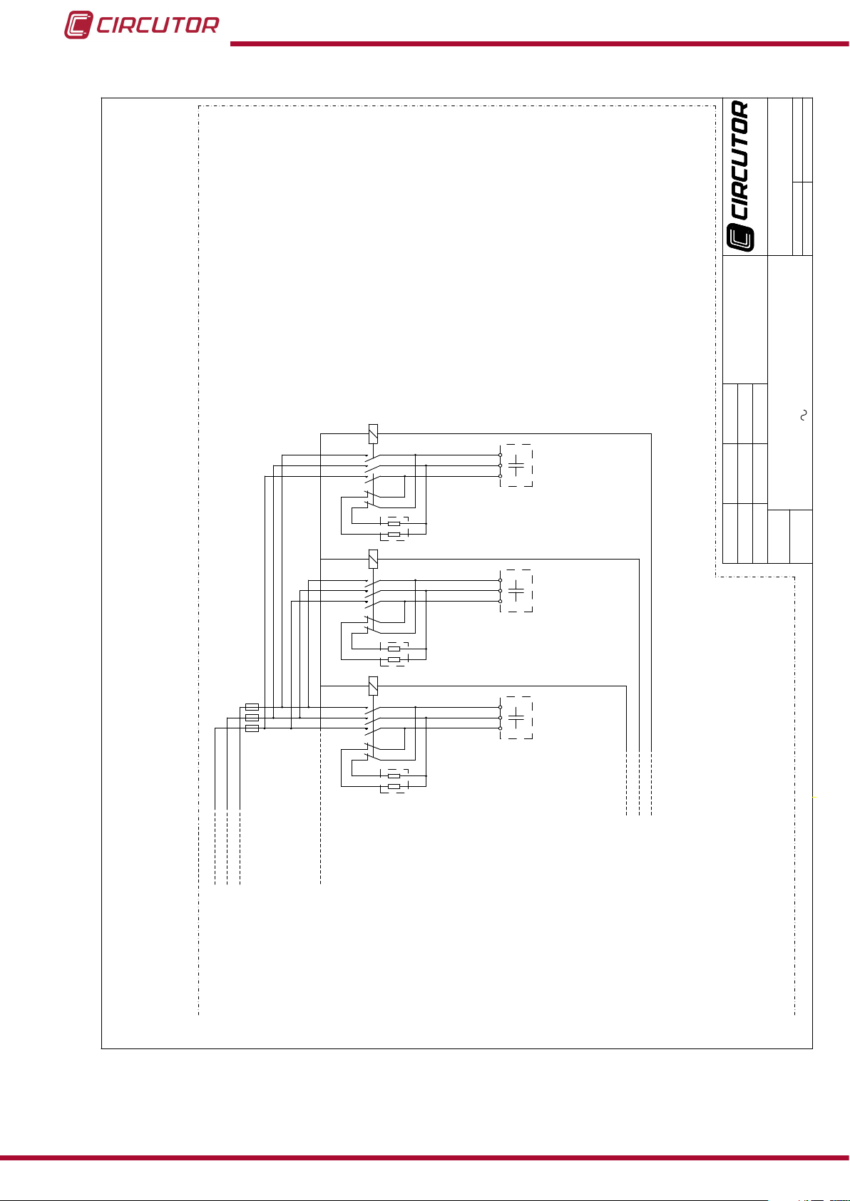
7.- STANDARD ELECTRICAL DIAGRAMS
UNE-EN 61439: 2012
The electrical diagrams indicated in this manual are for the standard models in each range, and
do not include the various additional accessories which these may equip, such as those listed
below:
Autotransformer for auxiliary power supply (in those models in which this is not tted as
standard).
Forced ventilation system.
General manual load cut-off switch.
Circuit breaker for general protection.
Earth leakage protection device.
Automatic regulator not for the Plug & Play Computer Max range.
And they are exclusively for the standard 3 x 440 V / 50 Hz rated voltage range, for use in threephase networks with a rated voltage of 3 x 400 V / 50 Hz.
24
Instruction Manual
Page 25

DENOMINACION
FECHA
UNIDAD DIM
ESCALA
APROBADO
DIBUJADO
NOMBRE
SUSTITUIDO POR
SUSTITUYE A
CODIGO
EQUIPO/S
02/10/2014
02/10/2014
C04 C04 C04
CIR_058
L1L2L3
L1L2L3
K1 K2
RG1
C1 C2
3N
N
K3
C3
50 Hz 440 V3N
OPTIM 3 P&P-XXX-440
BATERIA AUT. CONDENSADORES
RED CARGA
50 Hz 400 V
TI .../5A
Q1
Q2
TB1
65432
1
cos φ
Paso 1 Paso 2
S1 S2
S1 S2
Paso 3
Com
Regulador Automático
N
400Vac
0
S2
S1
POWER
SUPPLY
A B C D
08232 Viladecavalls (Barcelona)
Vial Sant Jordi s/n
OPTIM P&P Series
Figure 13: Standard electrical diagram of automatic capacitor banks in the OPTIM 3 P&P model.
Instruction Manual
25
Page 26

DENOMINACION
FECHA
UNIDAD DIM
ESCALA
APROBADO
DIBUJADO
NOMBRE
SUSTITUIDO POR
SUSTITUYE A
CODIGO
EQUIPO/S
02/10/2014
02/10/2014
C04 C04 C04C04 C04
CIR_058
L1L2L3
L1L2L3
K1 K2 K4
RG1
C1 C2 C4
3N
N
K3
C3
50 Hz 440 V3N
BATERIA AUT. CONDENSADORES SIN AUTOTRAFO
RED CARGA
50 Hz 400 V
TI .../5A
OPTIM 5 P&P-XXX-440
K5
C5
Q6
TB1
TB2
Q1 Q2 Q3 Q4 Q5
65432
1
cos φ
Paso 1 Paso 2 Paso 4
S1 S2
S1 S2
Paso 3
Com
Regulador Automático
N
Paso 5
400Vac
0
S2
S1
POWER
SUPPLY
A B C D
08232 Viladecavalls (Barcelona)
Vial Sant Jordi s/n
OPTIM P&P Series
26
Figure 14: Standard electrical diagram of automatic capacitor banks in the OPTIM 5 P&P model.
Instruction Manual
Page 27

DENOMINACION
FECHA
UNIDAD DIM
ESCALA
APROBADO
DIBUJADO
NOMBRE
SUSTITUIDO POR
SUSTITUYE A
CODIGO
EQUIPO/S
02/10/2014
02/10/2014
K06 K06 K06
C04 C04 C04
K06
C04
K06
C04
K06
C04
CIR_058
400Vac
0
S2
S1
12
11
10
9
876
5
4
3
2
1
COM
cos φ
S1 S2
Regulador Automático
S1 S2
Paso 1 Paso 2 Paso 4Paso 3 Paso 5 Paso 6
POWER
SUPPLY
0V
230V
400V
AUTOTRAFO
GRIS
AZUL
MARRÓN
A B C D
L1L2L3
L1L2L3
RED CARGA
RG1
50 Hz 440 V3N
3N 50 Hz 400 V
TI .../5A
N
K1 K2 K4
C1 C2 C4
K3
C3
K5
C5
K6
C6
PARTE 1
SIGUE EN PARTE 2
SIGUE EN PARTE 2
NH-00
NH-00
(SÓLO MODELOS CON MÁS
BATERIA AUT. CONDENSADORES CON AUTOTRAFO
DE 6 ESCALONES)
OPTIM 9 P&P-XXX-440
TB1
Q1
SIGUE EN
PARTE 2
AT1
08232 Viladecavalls (Barcelona)
Vial Sant Jordi s/n
TB1
OPTIM P&P Series
Instruction Manual
Figure 15: Standard electrical diagram of automatic capacitor banks in the OPTIM 9 P&P (1/2) model.
27
Page 28
DENOMINACION
FECHA
UNIDAD DIM
ESCALA
APROBADO
DIBUJADO
NOMBRE
SUSTITUIDO POR
SUSTITUYE A
CODIGO
EQUIPO/S
02/10/2014
02/10/2014
L1L2L3
50 Hz 440 V3N
OPTIM 9 P&P-XXX-440
BATERIA AUT. CONDENSADORES CON AUTOTRAFO
K7 K8
C7 C8
K9
C9
PARTE 2/2
VIENE DE PARTE 1/2
VIENE DE PARTE 1/2
VIENE DE PARTE 1/2
NH-00
CIR_058
08232 Viladecavalls (Barcelona)
Vial Sant Jordi s/n
K06 K06
C04 C04
K06
C04
Paso 7 Paso 8 Paso 9
8
7
9
F7 F8 F9
OPTIM P&P Series
28
Figure 16: Standard electrical diagram of automatic capacitor banks in the OPTIM 9 P&P (2/2) model.
Instruction Manual
Page 29

Q 1
RG1
L1L2L3
PARTE 1/2
AT1
OPTIM 8 P&P-XXX-440
50 Hz 440 V3N
BATERIA AUT. CONDENSADORES CON AUTOTRAFO
TB1
L1L2L3
RED
CARGA
3N 50 Hz 400 V
N
K1 K2 K3 K4
C1C1 C2C2 C3C3 C4C4
TB1
CODIGO
SUSTITUYE A
SUSTITUIDO POR
UNIDAD DIM
ESCALA
DENOMINACION
DIBUJADO
APROBADO
FECHA NOMBRE
EQUIPO/S
02/10/2014
02/10/2014
08232 Viladecavalls (Barcelona)
Vial Sant Jordi s/n
S1 S2
T.I.
Escalón 1
0V
230V
400V
AUTOTRAFO
C6
C5
C4
C3
C2
C1
COM
cos φ
Regulador Automático
Sigue en PARTE 2/2
Sigue en PARTE 2/2
Sigue en PARTE 2/2
Escalón 2 Escalón 3 Escalón 4
Sigue en PARTE 2/2
C8
C7
S1 S2
400Vac
0
S2
S1
POWER
SUPPLY
A B C D
12
11
10
9
GRIS
AZUL
MARRÓN
K06 K06 K06 K06
C04C04 C04C04 C04C04 C04C04
OPTIM P&P Series
Instruction Manual
Figure 17:Standard electrical diagram of automatic capacitor banks in the OPTIM 8 P&P (1/2) model.
29
Page 30

PARTE 2/2
OPTIM 8 P&P-XXX-440
50 Hz 440 V3N
BATERIA AUT. CONDENSADORES CON AUTOTRAFO
CODIGO
SUSTITUYE A
SUSTITUIDO POR
UNIDAD DIM
ESCALA
DENOMINACION
DIBUJADO
APROBADO
FECHA NOMBRE
EQUIPO/S
02/10/2014
02/10/2014
08232 Viladecavalls (Barcelona)
Vial Sant Jordi s/n
K06 K06
C04C04 C04C04
K06 K06
C04C04 C04C04
K5 K6
C5C5 C6C6
K7 K8
C7C7 C8C8
Viene de PARTE 1/2
Viene de PARTE 1/2
Viene de PARTE 1/2
Viene de PARTE 1/2
Viene de PARTE 1/2
6
5
Escalón 5 Escalón 6 Escalón 7 Escalón 8
8
7
OPTIM P&P Series
30
Figure 18:Standard electrical diagram of automatic capacitor banks in the OPTIM 8 P&P (2/2) model.
Instruction Manual
Page 31

Q 1
RG1
L1L2L3
PARTE 1/2
AT1
OPTIM SC8 P&P-XXX-440
50 Hz 440 V3N
BATERIA AUT. CONDENSADORES CON AUTOTRAFO
TB1
C1 C2 C3 C4
L1L2L3
RED
CARGA
3N 50 Hz 400 V
N
K1 K2 K3 K4
TB1
CODIGO
SUSTITUYE A
SUSTITUIDO POR
UNIDAD DIM
ESCALA
DENOMINACION
DIBUJADO
APROBADO
FECHA NOMBRE
EQUIPO/S
02/10/2014
02/10/2014
08232 Viladecavalls (Barcelona)
Vial Sant Jordi s/n
S1 S2
T.I.
0V
230V
400V
AUTOTRAFO
C6
C5
C4
C3
C2
C1
COM
cos φ
Regulador Automático
Sigue en PARTE 2/2
Sigue en PARTE 2/2
Sigue en PARTE 2/2
Sigue en PARTE 2/2
C8
C7
S1 S2
400Vac
0
S2
S1
POWER
SUPPLY
A B C D
12
11
10
9
GRIS
AZUL
MARRÓN
Escalón 1 Escalón 2 Escalón 3 Escalón 4
K06 K06 K06 K06
C04 C04 C04 C04
OPTIM P&P Series
Instruction Manual
Figure 19:Standard electrical diagram of automatic capacitor banks in the OPTIM SC8 P&P (1/2) model.
31
Page 32

PARTE 2/2
50 Hz 440 V3N
BATERIA AUT. CONDENSADORES CON AUTOTRAFO
OPTIM SC8 P&P-XXX-440
C5 C6 C7 C8
CODIGO
SUSTITUYE A
SUSTITUIDO POR
UNIDAD DIM
ESCALA
DENOMINACION
DIBUJADO
APROBADO
FECHA NOMBRE
EQUIPO/S
02/10/2014
02/10/2014
08232 Viladecavalls (Barcelona)
Vial Sant Jordi s/n
K06 K06 K06 K06
C04 C04 C04 C04
K5 K6 K7 K8
Viene de PARTE 1/2
Viene de PARTE 1/2
Viene de PARTE 1/2
Viene de PARTE 1/2
Viene de PARTE 1/2
6
5
8
7
Escalón 5 Escalón 6 Escalón 7 Escalón 8
OPTIM P&P Series
32
Figure 20:Standard electrical diagram of automatic capacitor banks in the OPTIM SC8 P&P (2/2) model.
Instruction Manual
Page 33

OPTIM P&P Series
8.- MAINTENANCE AND TECHNICAL SERVICE
In the case of any query in relation to unit operation or malfunction, please contact the
CIRCUTOR, SA Technical Support Service.
Technical Assistance Service
Vial Sant Jordi, s/n, 08232 - Viladecavalls (Barcelona)
Tel: 902 449 459 ( España) / +34 937 452 919 (outside of Spain)
email: sat@circutor.es
9.- GUARANTEE
CIRCUTOR guarantees its products against any manufacturing defect for two years after the
delivery of the units.
CIRCUTOR will repair or replace any defective factory product returned during the guarantee
period.
• No returns will be accepted and no unit will be repaired or replaced if it is not accompanied by a report indicating the defect detected or the reason for the return.
•The guarantee will be void if the units has been improperly used or the storage, installation and maintenance instructions listed in this manual have not been
followed. “Improper usage” is de ned as any operating or storage condition contrary to the national electrical code or that surpasses the limits indicated in the
technical and environmental features of this manual.
• CIRCUTOR accepts no liability due to the possible damage to the unit or other
parts of the installation, nor will it cover any possible sanctions derived from a possible failure, improper installation or “improper usage” of the unit. Consequently,
this guarantee does not apply to failures occurring in the following cases:
- Overvoltages and/or electrical disturbances in the supply;
- Water, if the product does not have the appropriate IP classi cation;
- Poor ventilation and/or excessive temperatures;
- Improper installation and/or lack of maintenance;
- Buyer repairs or modi cations without the manufacturer’s authorisation.
Instruction Manual
33
Page 34

10.- CE CERTIFICATE
OPTIM P&P Series
34
Instruction Manual
Page 35

OPTIM P&P Series
Instruction Manual
35
Page 36

CIRCUTOR, SA
Vial Sant Jordi, s/n
08232 -Viladecavalls (Barcelona)
Tel.: (+34) 93 745 29 00 - Fax: (+34) 93 745 29 14
www.circutor.es central@circutor.es
 Loading...