

Page 1
Low voltage capacitor bank with static operation.
OPTIM HYB Series
INSTRUCTION MANUAL
(M059B01-03-15A)
Page 2

OPTIM HYB Series
2
Instruction Manual
Page 3
OPTIM HYB Series
SAFETY PRECAUTIONS
Follow the warnings described in this manual with the symbols shown below.
DANGER
Warns of a risk, which could result in personal injury or material damage.
ATTENTION
Indicates that special attention should be paid to a speci c point.
If you must handle the unit for its installation, start-up or maintenance, the following
should be taken into consideration:
Incorrect handling or installation of the unit may result in injury to personnel as well as damage
to the unit. In particular, handling with voltages applied may result in electric shock, which may
cause death or serious injury to personnel. Defective installation or maintenance may also
lead to the risk of re.
Read the manual carefully prior to connecting the unit. Follow all installation and maintenance
instructions throughout the unit’s working life. Pay special attention to the installation standards of the National Electrical Code.
Refer to the instruction manual before using the unit
In this manual, if the instructions marked with this symbol are not respected or carried out correctly, it can
result in injury or damage to the unit and /or installations.
CIRCUTOR, SA reserves the right to modify features or the product manual without prior noti cation.
DISCLAIMER
CIRCUTOR, SA reserves the right to make modi cations to the device or the unit speci ca-
tions set out in this instruction manual without prior notice.
CIRCUTOR, SA on its web site, supplies its customers with the latest versions of the device
speci cations and the most updated manuals.
www.circutor.com
Instruction Manual
3
Page 4

OPTIM HYB Series
CONTENTS
SAFETY PRECAUTIONS .......................................................................................................................................3
DISCLAIMER ..........................................................................................................................................................3
CONTENTS ............................................................................................................................................................. 4
REVISION LOG .......................................................................................................................................................5
1.- VERIFICATION UPON RECEPTION ................................................................................................................. 6
1.1.- RECEPTION PROTOCOL .......................................................................................................................... 6
1.2.- TRANSPORT AND HANDLING .................................................................................................................6
1.3.- STORAGE...................................................................................................................................................7
2.- PRODUCT DESCRIPTION ................................................................................................................................ 8
2.1.- CAPACITOR BANK COMPONENTS ......................................................................................................... 8
2.1.1. HYBRID REGULATOR .........................................................................................................................8
2.1.2. CPC2 PANEL: ZERO SWITCHING CONNECTION CONTROL BY TWO SINGLE-PHASE
STAGES ........................................................................................................................................................ 13
2.1.3. SINGLE-PHASE POWER BLOCK ..................................................................................................... 14
2.1.4. THREE-PHASE POWER BLOCK ......................................................................................................14
2.1.5. MAINS CONNECTION TERMINALS ..................................................................................................14
3.- INSTALLATION ...............................................................................................................................................15
3.1.- PRELIMINARY RECOMMENDATIONS ...................................................................................................15
3.2.- PREPARATION .........................................................................................................................................16
3.3.- INSTALLATION LOCATION ..................................................................................................................... 17
3.4.-CONNECTION OF THE CAPACITOR BANK TO THE MAINS ................................................................. 17
3.5.-POWER CIRCUIT ...................................................................................................................................... 18
3.6.- EXTERNAL ISOLATION AND PROTECTION ELEMENTS ..................................................................... 19
3.7.- AUXILIARY CONTROL VOLTAGE ...........................................................................................................19
3.8.- EARTH CABLE CONNECTION ...............................................................................................................19
3.9.- CURRENT TRANSFORMER (CT) CONNECTION .................................................................................20
4.- START-UP OF A HYBRID CAPACITOR BANK ..............................................................................................22
4.1.- BEFORE START-UP .................................................................................................................................22
4.2.- START-UP .................................................................................................................................................22
4.3.- CHECKS ONCE THE CAPACITOR BANK HAS BEEN CONNECTED TO THE MAINS ........................ 26
5.- MAINTENANCE ............................................................................................................................................... 27
5.1.- SAFETY REGULATIONS .........................................................................................................................27
5.2.- MAINTENANCE WITH THE CAPACITOR BANK DISCONNECTED ...................................................... 27
5.2.1. BASIC MAINTENANCE PROTOCOL ................................................................................................27
5.2.2. TIGHTENING TORQUE OF THE ELECTRICAL CONNECTIONS ....................................................28
5.2.3. KEY POINTS FOR INSPECTING CONTACTORS .............................................................................28
5.2.4. KEY POINTS FOR INSPECTING STATIC SWITCHES ......................................................................29
5.2.5. KEY POINTS FOR INSPECTING CAPACITORS ...............................................................................29
5.2.6. KEY POINTS FOR INSPECTING THE REGULATOR .......................................................................29
5.2.7. CLEANING THE CABINET ................................................................................................................29
5.3.- MAINTENANCE WITH THE CAPACITOR BANK CONNECTED ............................................................30
5.4.- ENVIRONMENTAL CONDITIONS ............................................................................................................ 30
6.- TECHNICAL FEATURES ................................................................................................................................31
7.- OPTIM HYP TYPE DIAGRAM ......................................................................................................................... 32
8.- MAINTENANCE AND TECHNICAL SERVICE ................................................................................................34
9.- GUARANTEE ...................................................................................................................................................34
10.- CE CERTIFICATE .......................................................................................................................................... 35
4
Instruction Manual
Page 5

OPTIM HYB Series
REVISION LOG
Table 1: Revision log.
Date Revision Description
11/14 M059B01-03-14A Initial Version
02/15 M059B01-03-15A
Changes in the following sections:
6
Note: The images of the units are solely for the purpose of illustration and may differ from the
original unit.
Instruction Manual
5
Page 6
OPTIM HYB Series
1.- VERIFICATION UPON RECEPTION
1.1.- RECEPTION PROTOCOL
Check the following points when you receive the unit:
a) The unit meets the specications described in your order.
b) The unit has not suffered any damage during transport.
c) Perform an external visual inspection of the unit prior to switching it on.
d) Check that it has been delivered with the following:
- The unit manual.
- The CVM-MINI-RS485 quick installation guide.
If any problem is noticed upon reception, immediately contact the transport
company and/or CIRCUTOR's after-sales service.
1.2.- TRANSPORT AND HANDLING
The transport, loading and unloading and handling of the unit must be carried
out with proper precautions and using the proper manual and mechanical
tools so as not to damage it.
If the unit is not to be immediately installed, it must be stored at a location
with a rm and level oor, and the storage conditions listed in the technical
features section must be observed. In this case, it is recommended that the
unit be stored with its original protective packaging.
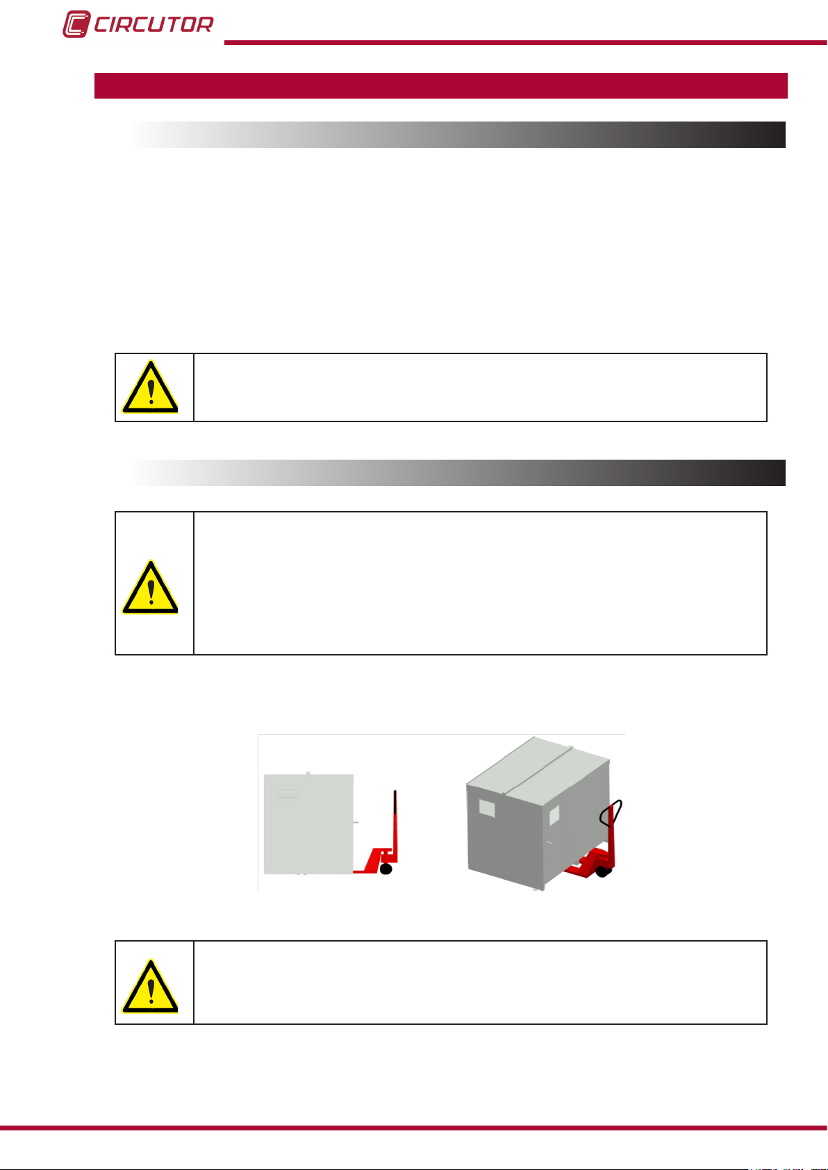
To move the unit a short distance, the unit's oor support proles facilitate handling with a pallet
jack or forklift. (Figure 1)
Figure 1: Transport with pallet jack.
The centre of gravity of some units may be found at a considerable height.
Therefore, when handling with a forklift, it is recommended that the unit be
securely fastened and that no abrupt manoeuvres made. The unit should not
be lifted more than 20 cm off the ground
6
Instruction Manual
Page 7
OPTIM HYB Series
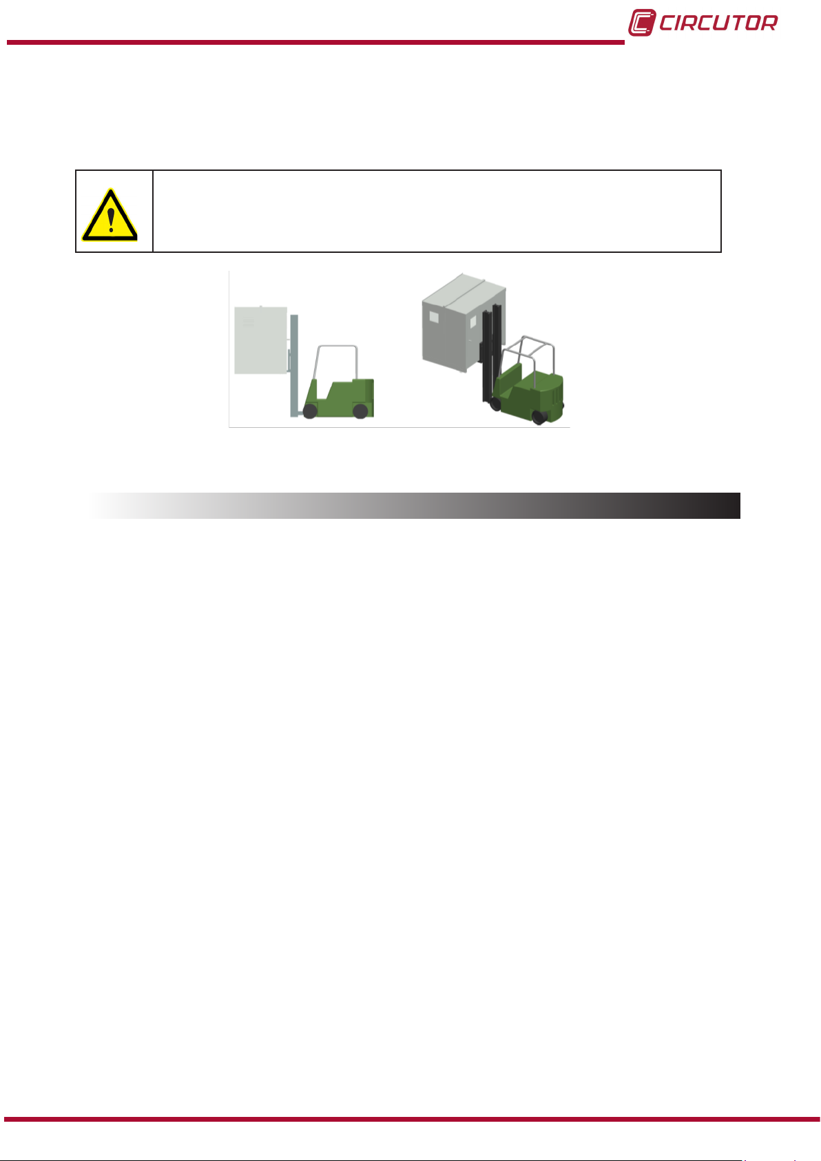
When unloading and moving the unit, use a forklift with forks long enough to support the entire
length of the base. Otherwise, the forks should be long enough to support at least ¾ of said
depth. The forks must be at and supported rmly by the base. Raise the cabinet by placing the
forks underneath the prole that supports the unit. (Figure 2).
There might be an offset in the centre of gravity from the centre of the cabinet,
as a result of the uneven distribution of loads inside the unit. The necessary
precautions must be taken to prevent the unit from tipping over during abrupt
operations.
Figure 2: Unloading with a forklift.
1.3.- STORAGE
The following storage recommendations must be followed for the hybrid capacitor banks:
Avoid placing them on uneven surfaces.
Do not store them in outdoor areas, humid areas or areas exposed to splashing
water.
Avoid hot spots (maximum ambient temperature: 40 ºC)
Avoid salty and corrosive environments.
Avoid storing the units in areas where a lot of dust is generated or where the risk of
chemical or other types of contamination is present.
Do not place any weight on top of the unit cabinets.
Instruction Manual
7
Page 8
OPTIM HYB Series
2.- PRODUCT DESCRIPTION
The purpose of this manual is to assist during the installation, start-up and maintenance of
OPTIM HYB series low voltage (LV) capacitor banks with static operation. Carefully read the
manual to achieve the best performance from those units.
2.1.- CAPACITOR BANK COMPONENTS
From the electrical standpoint, the unit is made up of the following blocks:
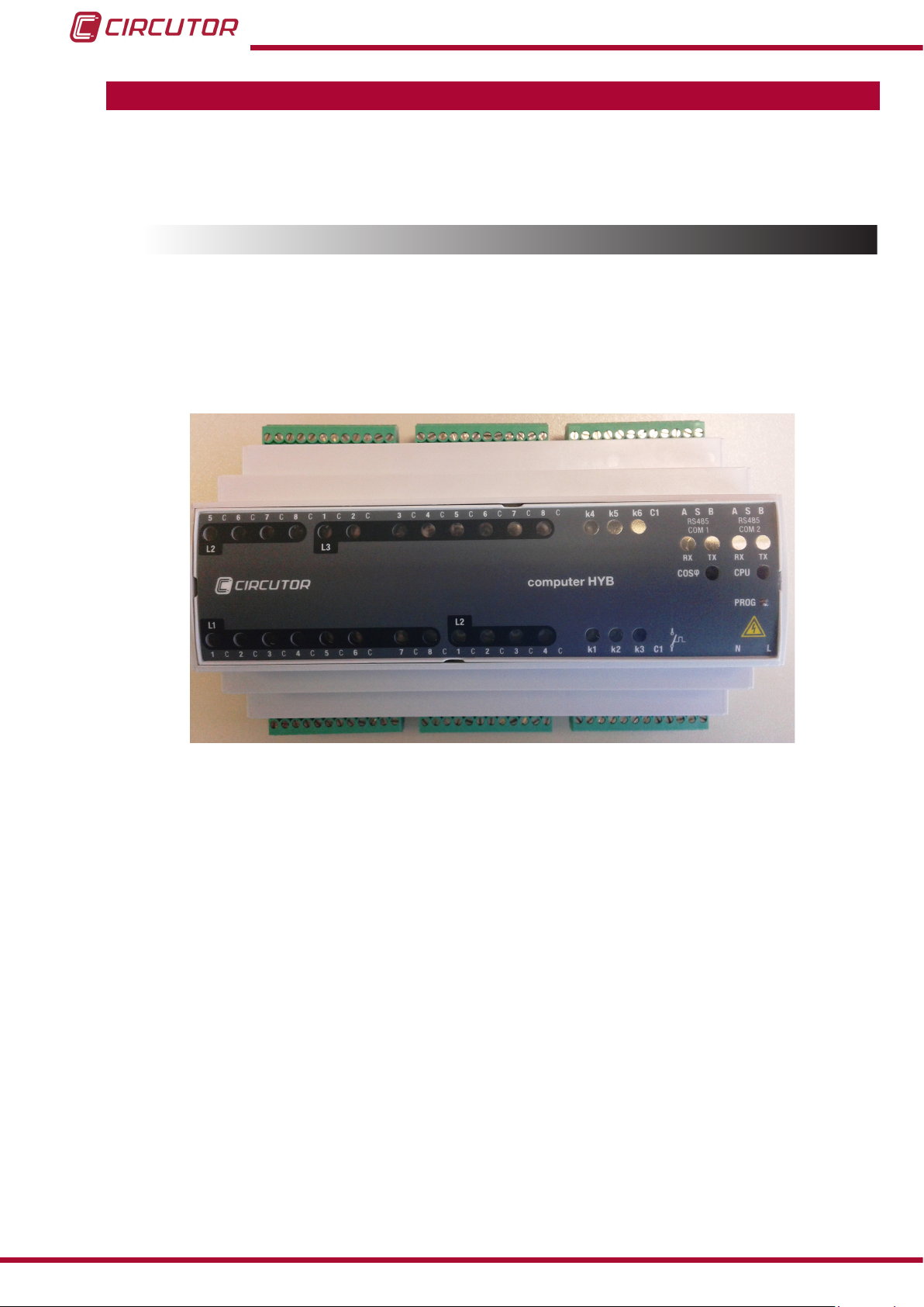
2.1.1. HYBRID REGULATOR
The hybrid capacitor banks are equipped with Computer HYB hybrid regulators (Figure 3).
Figure 3: Computer HYB Hybrid Regulator.
This regulator has two types of outputs (see the inputs and outputs identied in Figure 4.:
6 relay outputs with operating voltage of 250 V ~. and operating current of 4 A (AC1) for
the auxiliary control voltage of the electromechanical contactors that operate the three-phase
capacitors (three-phase steps of the OPTIM HYB capacitor bank).
24 static outputs to provide a 12 Vdc activation signal to the + and - inputs of the CPC2
connection controller boards at zero voltage difference. These boards control the semiconductor modules (thyristor-diode) and operate the single-phase capacitors (single-phase steps of
the OPTIM HYB capacitor bank).
The Computer HYB also has the following notable features:
The necessary information to calculate compensation demand by phase is provided by a
CVM-MINI-RS485-model power analyzer via RS-485 communications with the Modbus/RTU
protocol.
8
Instruction Manual
Page 9

OPTIM HYB Series
The communication parameters installed in the unit are:
Speed: 9600 bps, parity: No, data bits: 8, stop bits : 1
The standard OPTIM HYB models come with the CVM-MINI-RS485 analyzer built into the door
panel and programmed with the above values.
Note: If the OPTIM HYB capacitor bank does not include the CVM-MINI-RS485 analyzer and
you intend to use the existing unit in the installation to be compensated, with an RS-485 output
that is not being used to communicate with any data display system, the RS-485 communications must be programmed as indicated above.
(For more information, see the CVM-MINI-RS485 instruction manual at www.circutor.com).
The connection terminals for the external RS-485 signal are indicated in Figure 4.
Unit auxiliary power supply: 230 V ~ ± 10 % / 50-60 Hz.
Setpoint value of target cos phi set at 1, individually for each phase.
Regulation with a delay between connections/disconnections (response to compensation de-
mands) differentiated between the single-phase steps operated by semiconductors by default
of 1 s; and the three-phase steps by default of 20 s.
Reactive power compensation algorithm consisting of prioritising the connection of single-phase steps to compensate more quickly, and of substituting these connected single-phase
steps for a three-phase step when the compensation needs allow it.
Thus, the connected single-phase steps are replaced with a three-phase power step with an
equivalent phase if 20 s after the last single-phase stage is connected there is an available
three-phase step in the capacitor bank with the same three-phase value for the 3 connected
single-phase stages. In this situation, the single-phase steps would be disconnected and the
three-phase equivalent would be connected at the same time. In this way, the single-phase
stages are again enabled for fast connection if new three-phase or single-phase compensation
demands arise.
LEDs on the front panel indicating the connected stages, CPU operation, communication
status with the CVM-MINI-RS485 and alarm signals. See Figure 5 for a detailed description of
the LEDs on the Computer HYB front panel.
Additional input for RS-485 communications, for programming and control of internal regulator functions
Note: only for use by CIRCUTOR personnel or by those properly trained in its use.
Instruction Manual
9
Page 10
OPTIM HYB Series
The available combinations for standard models are selected through internal mini-dips.
The programming is done in-factory and should not be modied, except by
CIRCUTOR personnel or by those properly trained in its use.
Note: If you need to nd out the conguration of the mini-dips for each combination, please
contact CIRCUTOR technical assistance.
The available staging combinations as of the date of publication of this manual are exclusively
those indicated in Table 2:
Table 2:Available stage combinations.
Model Composition
OPTIM HYB1-90-440 (3 x 2 x 5) kvar / 230 V + (3 x 15) kvar / 400 V / 50 Hz
OPTIM HYB1-110-440 (3 x 2 x 5) kvar / 230 V + (4 x 15) kvar / 400 V / 50 Hz
OPTIM HYB2-165-440 (3 x 3 x 5) kvar / 230 V + (3 x 30) kvar / 400 V / 50 Hz
OPTIM HYB2-200-440 (3 x 3 x 5) kvar / 230 V + (4 x 30) kvar / 400 V / 50 Hz
OPTIM HYB2-270-440 (3 x 3 x 5) kvar / 230 V + (6 x 30) kvar / 400 V / 50 Hz
OPTIM HYB2-325-440 (3 x 3 x 10) kvar / 230 V + (3 x 60) kvar / 400 V / 50 Hz
OPTIM HYB3-400-440 (3 x 3 x 10) kvar / 230 V + (4 x 60) kvar / 400 V / 50 Hz
OPTIM HYB3-470-440 (3 x 3 x 10) kvar / 230 V + (5 x 60) kvar / 400 V / 50 Hz
OPTIM HYB3-540-440 (3 x 3 x 10) kvar / 230 V + (6 x 60) kvar / 400 V / 50 Hz
Digital input for external temperature relay signal (Figure 4) installed at the top of the heatsink
to dissipate the semiconductors. ( Normally in closed position )
In the event of an alarm, the connected steps would disconnect until the thermal relay returns
to its NC position and the condition triggering the alarm disappears.
The alarm situation is indicated by a combination of lit LEDs on the front panel of the Computer
HYB (See Figure 5).
Lack of compensation alarm, installed in the Computer HYB.
The alarm goes off when the non-compensated three-phase power is greater than 30% of the
total three-phase power available in the capacitor bank, or in other words, is greater than 30%
of its nominal power of 400 V~.
The alarm situation is indicated by the cos φ LED being lit on the front panel of the Computer
HYB. (See Figure 5).
2.1.1.1. Computer HYB Regulator Connections.
Note : See the general connection diagram in “7.- OPTIM HYP type diagram”
The regulator comes fully connected, expect in the case of units that do not have the CVM-MINI-RS485 analyzer.
In this case, you must connect the CVM-MINI-RS485 communications output to the ASB COM2
terminal of the Computer HYB, using a shielded communication cable with at least 3 wires and
with a section of at least 0.25 mm2.
10
Instruction Manual
Page 11
NC THERMAL RELAY
OPTIM HYB Series
Any modication to the regulator connections must be performed exclusively
by CIRCUTOR personnel or by those properly trained in its use
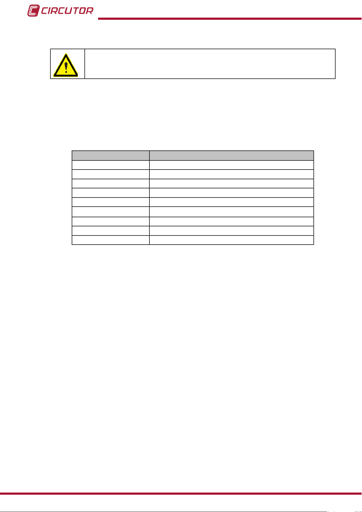
The regulator's input and output terminals are shown in Figure 4.
OUTPUTS 5 AND 8
PANEL CONTROL CPC4
SINGLE-PHASE STAGES L2
OUTPUTS 1 AND 8 PANEL CONTROL CPC4
SINGLE-PHASE STAGES L3
OUTPUTS 1 AND 3
CONTACTORS
CONTROL
AUXILIAR SIGNAL
INPUT RS485
SIGNAL INPUT RS485
FROM CVM-MINI-RS485
5 C 6 7 8 1 2C C C C C 3 C 4 5 6 7 8C C C C C
L2
L1
1 C 2 3 4 5 6C C C C C 7 C 8 1 2 3 4C C C C C
OUTPUTS 1 AND 8 PANEL CONTROL CPC4
SINGLE-PHASE STAGES L1
L3
L2
OUTPUTS 1 AND 4
PANEL CONTROL CPC4
SINGLE-PHASE STAGES L2
Figure 4: Terminals on the Computer HYB Hybrid Regulator.
K4 k5 k6 SC1 A B SA B
COM1 COM2
K1 k2 k3 C1
OUTPUTS 1 AND 3
CONTACTORS
CONTROL
POWER
SUPPLY
INPUT SIGNAL
LN
2.1.1.2. Indicator LEDs on the Computer HYB regulator.
The Computer HYB regulator has a series of LEDs on its front panel to indicate the connected
stages, CPU operation, communication status with the CVM-MINI-RS485 and alarm signalling.
The different LEDs on the Computer HYB front panel are shown in Figure 5.
Instruction Manual
11
Page 12

Figure 5: LEDs on the Computer HYB Hybrid Regulator.
Table 3:LEDs on the Computer HYB Hybrid Regulator.
LED Description
L1/1 ...L1/8
L2/1 ...L2/8
L3/1 ...L3/8
K1...K6
RS485 COM 1: RX and TX
RS485 COM 2: RX and TX
CPU
cosφ
PROG
RS485 COM 2 RX and TX
+
L1/2
+
CPU
L1/3 + CPU
OPTIM HYB Series
Indicates the activation of the single-phase step between phase L1
and Neutral controlled by that output.
Indicates the activation of the single-phase step between phase L2
and Neutral controlled by that output.
Indicates the activation of the single-phase step between phase L3
and Neutral controlled by that output.
Indicates the activation of the three-phase step controlled by that
output.
Indicates communication with the Computer HYB through the
COM 1 communication channel, which is used for in-factory programming.
If the 2 LEDs ash alternately at an approximate rate of once per
second, this indicates the correct functionality of communications
between the Computer HYB regulator and the CVM-MINI-RS485
from which the electrical parameter values are obtained to perform
mains compensation.
If it ashes at an approximate rate of once per second, this indicates the correct functionality of the Computer HYB regulator's
microprocessor.
Indicates the activation of the alarm due to lack of compensation, if
the uncompensated three-phase power is greater than 30% of the
value of the total available three-phase power in the capacitor bank,
which is to say that it is greater than 30% of its nominal power of
400 V ~, for a period of 15 consecutive minutes.
If pressed while the Computer HYB regulator is connected to the
power supply, the default communication values of the regulator
are restored.
If these 4 LEDS are ashing at a very fast rate, this indicates a communications problem between the Computer HYB regulator and
the CVM-MINI-RS485.
Check the connection of the RS-485 communication cable and the
conguration of the CVM-MINI-RS485 communication parameters.
If these 2 LEDs are ashing at a very fast rate, this indicates that
there is an alarm condition due to overheating.
The thermal relay located in the heatsink has been activated, with
its position changing from NC to NO.
12
Instruction Manual
Page 13

Th-D 1
PPPC1
1 3
2
Q
1
U1
U2
1
32
4
5
Radiador
PLACA
1G1
+
-
CPC2
CONTROL
1K1
12VDC
Alimentación Potencia
Conexión a Condensador Monofásico
Mando
OPTIM HYB Series
2.1.2. CPC2 PANEL: ZERO SWITCHING CONNECTION CONTROL BY TWO SINGLE-PHASE STAGES
The static capacitor banks come equipped with CPC2 panels in the single-phase stages.
The role of the CPC2 panels is to control the zero switching connection of the thyristor-diode
modules that operate the single-phase stages, preventing connection current transients.
The typical connection diagram of a step can be seen in Figure 6 and with more detail in section
“7.- OPTIM HYP type diagram”.
The CPC panels are activated via a 12 Vdc signal supplied by the Computer HYB regulator's
outputs. The standard CPC2 panels are designed to always be used between phase and neutral on networks with phase-neutral voltage of Umax = 254 V.
Instruction Manual
Figure 6: Basic connection diagram of the CPC2 to the power block.
13
Page 14

OPTIM HYB Series
2.1.3. SINGLE-PHASE POWER BLOCK
The single-phase power block of a OPTIM HYB unit consists of 6 to 9 groups of thyristor-diode
semiconductors + single-phase capacitor + unipolar circuit breaker.
Each single-phase group consists of a cylindrical capacitor, an aluminium cylindrical housing, 2
terminals, 1 thyristor-diode module joined to a general heatsink and the appropriate protection
element for the power of the module (unipolar circuit breaker). For more detailed information,
see section “7.- OPTIM HYP type diagram”.
2.1.4. THREE-PHASE POWER BLOCK
The three-phase power block of a OPTIM HYB unit consists of 3 to 6 groups, each group containing:
1 three-pole electromechanical contactor, appropriate for connecting capacitive loads
(application category AC-6), with a pre-inserted impedance block to limit the capacitor's connection current and fast discharging resistors to ensure a minimal residual voltage in the capacitor when it is connected.
The contactors have 1 x 230 V / 50-60 Hz (± 10 %) operation coils.
1 three-phase capacitor, in a cylindrical aluminium housing, with a rated voltage of 440 V.
1 three-pole circuit breaker with a calibre suitable for the stage power, with a C Curve and
Ics = 6 kA (400 V).
For more detailed information, see section “7.- OPTIM HYP type diagram”.
2.1.5. MAINS CONNECTION TERMINALS
The mains connection terminals of a OPTIM HYB unit consist of the input terminals of the quad-
rupole isolating switch, which comes standard with the capacitor bank.
For more detailed information, see section “7.- OPTIM HYP type diagram”.
14
Instruction Manual
Page 15

OPTIM HYB Series
3.- INSTALLATION
3.1.- PRELIMINARY RECOMMENDATIONS
In order to use the unit safely, it is critical that individuals who handle it follow the
safety measures set out in the standards of the country where it is being used,
use the personal protective equipment necessary, and pay attention to the various warnings indicated in this instruction manual.
Installation or maintenance personnel should read and understand this manual
before operating the unit.
A copy of this manual should always be available to maintenance personnel for
reference purposes
Connecting the unit to the public mains must be carried out in compliance with
the EN-IEC60204-1 standard, regarding the safety of LV electrical installations.
It is recommended that several personnel are present when handling the unit for
installation or maintenance.
If damage or faults are detected during unit operation, or in circumstances that
compromise safety, immediately stop work in that area and disconnect the unit in
order to check it without voltage.
The manufacturer of the unit is not responsible for any damages resulting from failure by the
user or installer to heed the warnings and/or recommendations set out in this manual, nor for
damages resulting from the use of products or accessories that did not come with the unit or
that were made by other manufacturers.
If an anomaly or malfunction is detected in the unit, do not use it to perform any operation.
Modifying, upgrading or rebuilding the unit without written authorisation from the
manufacturer is prohibited.
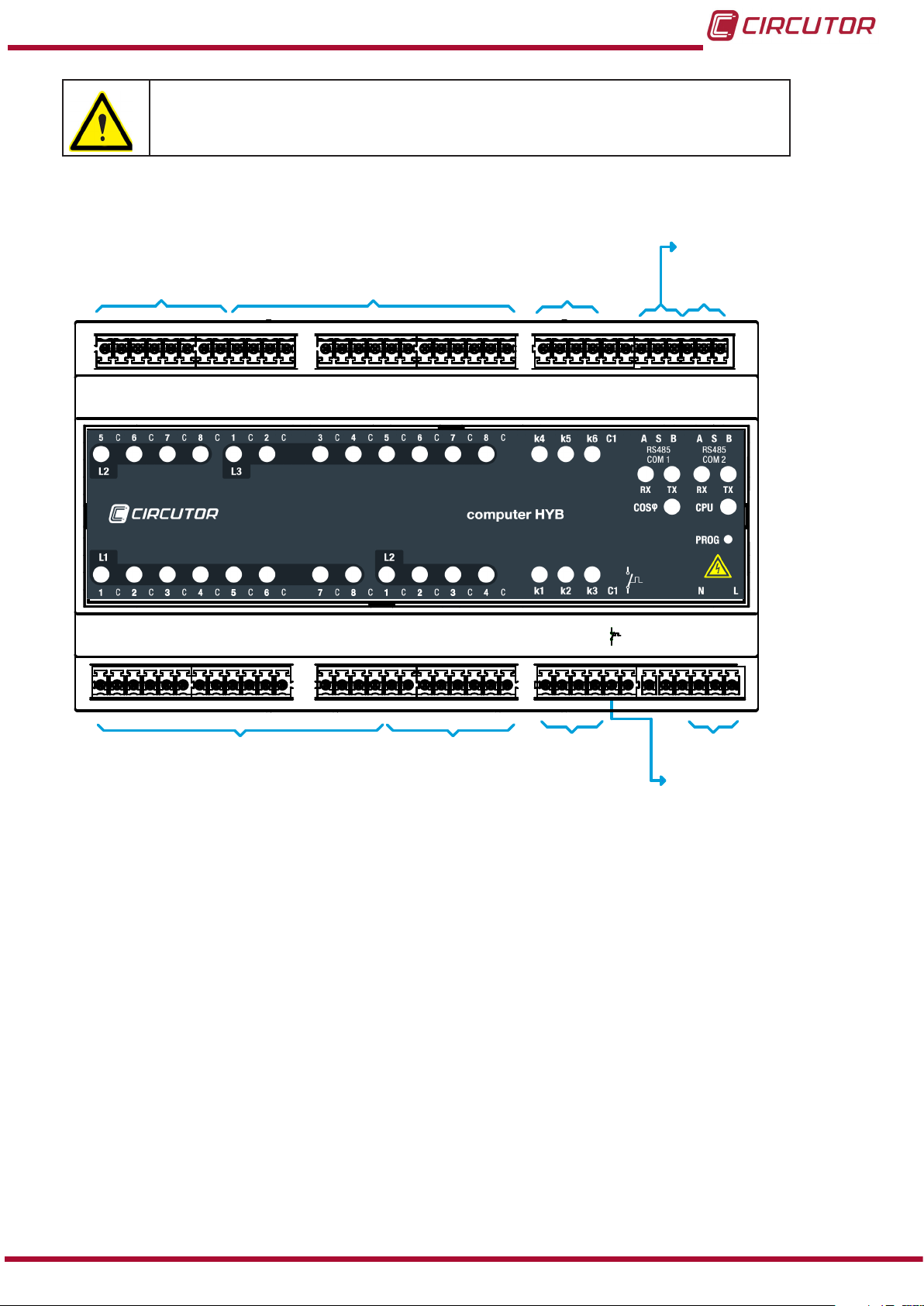
The installation, operation and maintenance of low voltage (LV) units must only
be carried out by authorised installers. LV regulations (Art. 22) specically dene
the requirements that authorised installers must meet.
Do not access the active elements of a capacitor bank with static operation that
has been powered and might have voltages present. Wait at least 5 minutes after the power supply has been disconnected.
Instruction Manual
15
Page 16

OPTIM HYB Series
Do not touch the terminals or active parts of the unit until you have veried that
voltage is not present. If you have to handle or touch the terminals or other control
panel components, use adequately insulated personal protection equipment and
tools.
After any maintenance and before re-connecting the power supply to the unit,
check that its enclosure is properly closed and that no items or tools were left
inside that could cause a short-circuit.
Do not disconnect the current transformer secondary without short-circuiting it
rst. The operation of a current transformer with an open secondary will cause an
overvoltage that could damage it and electrocute the person handling it.
3.2.- PREPARATION
The CIRCUTOR OPTIM HYB static capacitor banks come ready for easy installation and start-
up.
Remove the packaging of the unit and verify that its electrical features are suitable for connection to the available mains. To do so, check the features label located inside the cabinet next to
the regulator, see Figure 7 .
Key data to be checked:
Mains frequency and voltage, Un / fn.
Nominal power of the capacitor bank, Qn (kvar) and composition
Current consumption, I
. This current must be considered to select the proper size
max
of the power supply cable of the unit and ultimately the circuit breakers and protection
elements to be connected in front of it.
Environmental conditions. (See “6.- TECHNICAL FEATURES”)
16
Figure 7: Features label.
Instruction Manual
Page 17

OPTIM HYB Series
3.3.- INSTALLATION LOCATION
It is important to maintain a minimum distance around the unit to facilitate cooling.
In self-supporting cabinets, the back and front sides of the cabinet must be kept at least 50 cm
away from walls of other units and other infrastructure to allow for ventilation.
In terms of the side walls, it is recommended that a separation of 10 cm be maintained between
adjacent cabinets.
On wall-mounted cabinets, it is recommended that at least 20 cm of separation be maintained
between the sides of adjacent cabinets.
Note: Hybrid units have aluminium heatsinks to cool the thyristors. Periodically clean these
radiators with a brush or with compressed air and ensure that they have maximum ventilation.
Make sure the unit can be accessed easily.
The environmental conditions of the location where the unit is installed must not exceed the
limits set forth in the technical features (See “6.- TECHNICAL FEATURES”)
To ensure proper ventilation, the unit must be installed in a vertical position.
In accordance with LVR, once the unit is installed, it must be protected against direct and indirect contacts; therefore, a circuit breaker and earth leakage protection for the capacitor bank
power supply line should be installed.
3.4.-CONNECTION OF THE CAPACITOR BANK TO THE MAINS
Check that the rated voltage of the capacitor bank matches the voltage between
phases of the grid to which it is being connected.
For feeding cables into the capacitor bank cabinet, always use the entry point
enabled for this purpose (See Figure 8 showing the cable entry point on OPTIM
HYB 2 models).
If another part of the cabinet is cut out to be used for cable entry, the CIRCUTOR manufacturer's guarantee shall be rendered void.
Do not cut holes in other parts of the cabinet for feeding cables through or for
installing support brackets.
It may produce trimmings that can cause short-circuits.
Instruction Manual
17
Page 18

OPTIM HYB Series
Figure 8: Cable entry point on the OPTIM HYB 2 model.
3.5.-POWER CIRCUIT
Connect input terminals L1, L2, L3 and N (power circuit) to the mains using a cable with a proper section width, in accordance with the LVR, ITC-BT-19.
Generally, the cables of the phases are according to the following colour code: L1 (black), L2
(brown), L3 (grey) and the neutral conductor N (blue).
To determine the size of the phase cables, the maximum nominal current I
label and a transient overload of up to 1.5 times I
be taken into account. The neutral cable
max
shown on the unit
max
must have the same section as the phase conductor.
18
Figure 9: Input terminals L1, L2, L3 and N for connecting OPTIM HYB capacitor banks to the mains.
Instruction Manual
Page 19

OPTIM HYB Series
3.6.- EXTERNAL ISOLATION AND PROTECTION ELEMENTS
The capacitor bank has a manual internal quadrupole isolator, but it must be connected to a
line that is protected by a circuit breaker as well as earth leakage protection at the header, in
accordance with Spanish Low-Voltage Electrotechnical Regulations (LVR) and depending on
the earthing system of the installation.
The protection elements, isolation switches and/or switches that are added externally to the capacitor bank must be of a minimum size to withstand a current 1.5
times greater than what is indicated on the label (LVR, ICT-BT-48)
If an earth leakage protection for the capacitor bank is installed, its sensitivity and
trip delay must be adjustable.
3.7.- AUXILIARY CONTROL VOLTAGE
Standard OPTIM HYB capacitor banks for 3 x 400 V / 1 x 230 V networks do not require an
auxiliary power supply.
3.8.- EARTH CABLE CONNECTION
Connect the earth terminal of the capacitor bank housed inside the operations panel of the unit
(see Figure 10) to the exterior earth connection.
The earth cable section must be selected in accordance with the admissible current limits established in the LVR (ITC-BT-19 – Indoor or receiver installations).
Figure 10: Earthing terminal for external earthing connection of the OPTIM HYB capacitor banks
Instruction Manual
19
Page 20
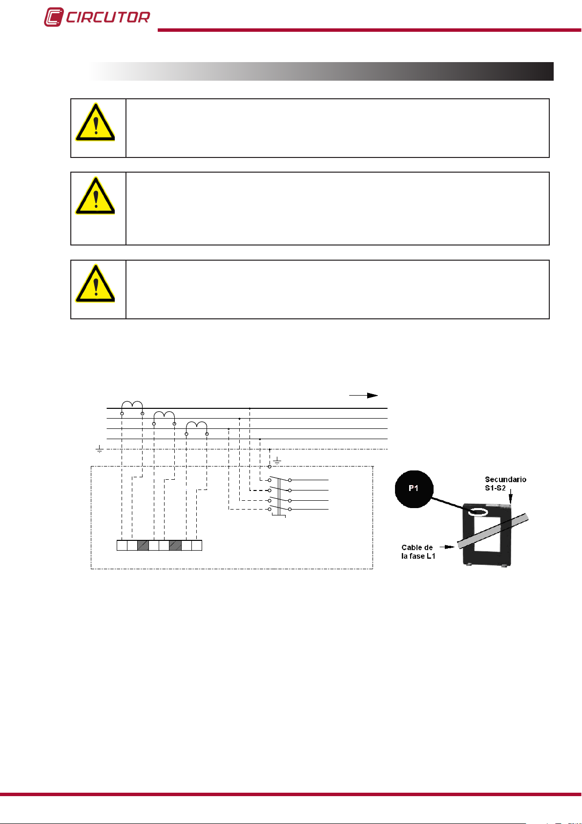
3.9.- CURRENT TRANSFORMER (CT) CONNECTION
L1
L2
L3
N
RED CARGA
3x400 V / 1x230 V - 50 Hz
L1
L2
L3
S1
N
TB1
BATERÍA DE
CONDENSADORES
1S1 1S2
S1 S2
S1 S2
S1 S2
T.I.1
T.I.2
T.I.3
2S1 2S2 3S1 3S2
For standard units that come with a CVM-MINI-RS485 power analyzer: You
must place 3 current transformers (CT) outside the capacitor bank, one at
each phase, measuring the total current of the load plus the capacitor bank
itself (Figure 11).
The standard transformer must have a nominal output of 5 A at the secondary.
For correct measurement of powers and angles, you must connect the CT to
each phase with the direction of the current from P1 to P2 (Figure 11) and connect
the secondary (terminals S1, S2) to the terminals with the same name on the capacitor bank (see Figure 11 and Figure 12).
Avoid the ow of current through the CT's primary before connecting the secondary to the S1 and S2 terminals of the capacitor bank.
If the CT must be installed while the installation is under load, short-circuit S1 and
S2 while they are not connected to the capacitor bank.
OPTIM HYB Series
The current value of the CT primary winding must be equal to or slightly greater than the size of
the mains switch of the installation. Therefore, the CT must be able to measure the maximum
current expected to be consumed by all the loads being compensated.
Figure 11: Installation of external current transformers (CT).
The connection point of the CT for a capacitor bank that compensates an entire installation is
after the mains switch of the installation.
20
To prevent excessive attenuation of the signal, it is recommended that the minimum secondary
section winding cable size (terminals S1, S2) is at least 2.5 mm2.
Instruction Manual
Page 21

OPTIM HYB Series
Figure 12: Current transformer (CT) connection terminals.
Once the cables are installed, disconnect the jumper connecting the 3 S1 and S2 terminals of
the capacitor bank (see Figure 13)
Figure 13: Jumper for short-circuiting the secondary winding of the current transformer (CT).
Any time you wish to change or disconnect a current transformer that is already
installed, it is important to install the jumper connecting S1 and S2.
Instruction Manual
21
Page 22

OPTIM HYB Series
4.- START-UP OF A HYBRID CAPACITOR BANK
4.1.- BEFORE START-UP
Hybrid capacitor banks come with a computer HYB-type power factor regulator and standard
models come with a CVM-MINI-RS485-model power analyzer.
The installation, operation and maintenance of LV units must only be carried out
by authorised installers. LV regulations (Art. 22) specically dene the requirements that authorised installers must meet.
For optimal start-up, the load status of the installation must be at least 30%-40%
of the rated load for which the capacitor bank is sized.
4.2.- START-UP
Apply the safety regulations listed in section “3.- INSTALLATION” of this manual
before operating the units.
The National Electric Code of the country where the capacitor bank is installed or operated should be strictly followed.
1.- Open the door to the unit and make sure that the general quadrupole switch inside the ca-
pacitor bank is open (in OFF position).
2.- Make sure that all the protection circuit breakers for operation and power are open (in O
position, with the lever in the down position).
3.- Check that the 3 bridges that join the 3 S1 and S2 terminals of the current measurement circuit of the capacitor bank's CVM-MINI-RS485 analyzer are removed (if the unit has this circuit).
4.- Close (put in I position, with the lever in up position) the quadrupole circuit breaker that provides the auxiliary power supply to the unit, along with the power supply to the Computer HYB
and the CVM-MINI-RS485 (indicated as auxiliary power supply protection) in Figure 14).
22
Instruction Manual
Page 23

set
Pr i U
000001
set
pr i a
00005
max
OPTIM HYB Series
Figure 14: Quadrupole circuit breaker for the auxiliary power circuit.
5.- Connect the power supply of the OPTIM HYB capacitor bank, closing the general quadru-
pole switch inside the capacitor bank using its lever (ON position) and check that the CPU LED
and the RS485 COM 2 RX and TX LEDs light up immediately and ash at an approximate rate
of once per second.
This indicates the correct operation of the Computer HYB processor and correct communications between the Computer HYB and the CVM-MINI-RS485, respectively.
6.- Check that the CVM-MINI-RS485 (in the OPTIM HYB models that come equipped with it)
installed in the door of the capacitor bank lights up, and then program the primary value of the
current transformers that provide the measurement signal to the analyzer. Follow the steps
below for this programming:
A.- Access the MEASUREMENT Setup by pressing the SETUP key until the unit enters
into programming mode.
The screen shown in Figure 15 will appear on the display, which allows you to program
the voltage primary.
Note : This programming is not necessary for 3 x 400 V / 1 x 230 V networks.
Figure 15: Programming of the voltage primary, CVM-MINI-RS485.
B.- Press the key until the screen shown in Figure 16 appears on the display, which
allows you to program the current transformer primary.
To enter or modify the current primary, press the
Instruction Manual
Figure 16: Programming of the current primary, CVM-MINI-RS485.
key repeatedly to increase the
23
Page 24

min
min
OPTIM HYB Series
value of the ashing digit.
When the on-screen value is that desired, press the
key to go to the next digit to
modify the other values.
If you press the
key after changing the last digit, it will jump back to the rst digit so
you can modify the previously programmed values again.
To validate the information and go to the next programming step, press .
Note: The analyzer does not record programming changes until the programming is complete;
if it is reset before the programming is completed, the conguration will not be stored in the
memory.
Note: For more basic information see the quick installation guide for the CVM-MINI-RS485
which is included with the documentation you received with the unit, and for full information see
the complete unit manual on the web site: www.circutor.com.
7.- Once you have nished programming the CVM-MINI-RS485, check the readings on the
display: phase-phase voltage and phase-neutral voltage values for each phase, current of each
phase, active power of each phase, reactive power of each phase and power factor (cos φ) of
each phase.
It is important to conrm that the values on the display are logical in terms of the features of the
network being compensated.
It is essential to ensure the correct correlation between the voltage and current measurement
signals (phase concordance) and that there are no negative active power values, which would
indicate that there is a current transformer with inverted polarity or an incorrect phase sequence
between voltages and currents. For example: if the current signal for phase 1 does not corre-
spond with the voltage phase 1, and instead corresponds with another phase.
If these incorrect values are shown on the display, recheck the position of the current transformers and check for any connection errors that may have occurred.
As a guideline, remember that in a standard installation with a normal load level, the cos φ
measured by each phase should range between 0.5 and 0.95 inductive.
Figure 17 shows the correct connection of the current transformers with respect to the connection of the OPTIM HYB capacitor bank to the network.
24
Instruction Manual
Page 25

L1
L2
L3
N
RED CARGA
3x400 V / 1x230 V - 50 Hz
L1
L2
L3
S1
N
TB1
BATERÍA DE
CONDENSADORES
1S1 1S2
S1 S2
S1 S2
S1 S2
T.I.1
T.I.2
T.I.3
2S1 2S2 3S1 3S2
OPTIM HYB Series
Figure 17: Connection of 3 current transformers (CT) to the OPTIM HYB capacitor bank.
8.- Once the OPTYM HYB capacitor bank and the current transformers are connected, discon-
nect the panel by opening the general quadrupole switch inside the capacitor bank (OFF position) and check that the LEDs of the Computer HYB regulator turn off, indicating no voltage.
Then close (put in I position, with the lever in up position) all the protection circuit breakers
on the power circuit, including the three-pole circuit breakers on the three-phase stages and
the unipolar circuit breakers on the single-phase stages.
Any operation with the protection circuit breakers on the power circuit or
auxiliary power supply circuit of OPTYM HYB capacitor banks must always be
performed with no voltage, i.e., with the general quadrupole switch on the inside
of the capacitor bank open (in OFF position).
9.- Reconnect the power supply of the OPTIM HYB capacitor bank, closing the general quadrupole switch inside the capacitor bank using its lever (ON position).
Check that the CPU LED and the RS485 COM 2 RX and TX LEDs light up immediately and
ash alternately at an approximate rate of once per second.
Close the door of the capacitor bank and wait for the stage connection operations to start,
based on the compensation needs of the network for each particular case.
The OPTIM HYB capacitor bank is now running and there is no need for additional adjustments.
Instruction Manual
25
Page 26

OPTIM HYB Series
4.3.- CHECKS ONCE THE CAPACITOR BANK HAS BEEN CONNECTED TO THE
1.- After start-up, make sure that the unit is operating correctly. An indication of proper functioning is that, once the reaction time of the regulator has passed, the CVM-MINI-RS485 display
will show a cos φ with a value of close to 1 in each phase, and the reactive power value for each
phase will be small compared to the active power value for each phase.
2.- Check that the power supply voltage does not exceed the nominal value +10% (IEC 60831-
1), by looking at the readings of the CVM-MINI-RS485 analyzer.
3.- Check the current absorbed by each capacitor group.
Under normal working conditions, it must be close to the nominal values (See Table 8) and nev-
er more than 1.3 times this value continuously.
Continuous consumption in all the capacitors over the nominal value may be caused by the
presence of harmonics in the grid or an excessively high power supply voltage. Both circumstances are harmful for capacitors and control panels.
If there is unusual consumption in only some of the capacitors, it is a sign that there are damaged capacitors.
4.- In accordance with the IEC 60831-1 Standard, the capacitor is prepared to operate at the
permanent voltage assigned to it and with an overvoltage of up to 10% for 8 out of every 24
hours.
Check the working temperature of the capacitors after they have been operating
for 24 hours.
The capacitor capsule must be under 40 ºC.
26
Instruction Manual
Page 27

OPTIM HYB Series
5.- MAINTENANCE
5.1.- SAFETY REGULATIONS
Take the safety regulations listed in section of this manual into account before
operating the units “3.1.- PRELIMINARY RECOMMENDATIONS”
The National Electric Code of the country where the capacitor bank is installed or
operated should be strictly followed.
5.2.- MAINTENANCE WITH THE CAPACITOR BANK DISCONNECTED
5.2.1. BASIC MAINTENANCE PROTOCOL
Monthly:
Visually inspect the capacitors.
Check the protection circuit breakers.
Control the ambient temperature (average of 30 ºC In accordance with IEC 60831 ).
Control the service voltage (especially during moments of low load, it must not exceed
the nominal +10%).
Bi-annually:
Keep the capacitor terminals clean.
Check that the thyristors are not short-circuited.
To do so, check that if you cut the power supply of the regulator there is no current in any
of the capacitor phases.
Check that the capacitor current is not lower than 75% nor greater than 120% of the
nominal value by phase and that there is no phase unbalance greater than 15%.
Annually:
Check the capacity of the capacitors at the different steps.
An indirect verication can be performed by checking that the consumption matches the
value indicated in Table 8, with a maximum deviation of ± 10%.
Check the tightening torque of all terminal connections on the different power elements.
Inspect the fuses.
- Power Circuit: Check the continuity and temperature of the unipolar and three-pole
circuit breakers.
- Control Circuit: Check the continuity and temperature of the quadrupole circuit break-
er.
Instruction Manual
27
Page 28

5.2.2. TIGHTENING TORQUE OF THE ELECTRICAL CONNECTIONS
The connections must be tight.
The torques of the circuit breakers are indicated in Table 4 and Table 5.
Table 4:Torques of power cables to unipolar and three-pole circuit breakers.
Circuit breaker Torque (Nm)
In ≤ 3 x 63 A 2
In ≤ 2 x 63 A 2
Table 5:Torques of cables to connector terminals
Model Auxiliary (Nm) Power (Nm)
MC -12 1.3 1.6
MC -18 1.3 2.2
MC -32 1.3 2.9
MC -40 1.3 4
MC -50 1.3 4.5
MC -65 1.3 4.5
MC -75 1.3 4.5
MC -85 1.3 5.1
OPTIM HYB Series
5.2.3. KEY POINTS FOR INSPECTING CONTACTORS
Check that the plastic parts are not blackened and do not show signs of burning or hardening.
Check that the head is properly inserted.
Check the tightness of cables and terminals, as shown in Table 5.
The terminals must be clean.
If the capacitor bank includes RD discharge resistors, check they are in good condition (that
they are not open or show signs of burning). (Figure 18)
28
Figure 18: Connection of the discharge resistors.
Cleaning the contactors: In dirty environments (dust, sawdust, rust particles, etc.) vacuum
the contactor periodically.
There is no estimated time frame for cleaning, it depends on the amount of dirt that is inside
the bank.
Instruction Manual
Page 29

OPTIM HYB Series
5.2.4. KEY POINTS FOR INSPECTING STATIC SWITCHES
Check that the plastic parts are not blackened and do not show signs of burning or hardening.
Check that the head is properly inserted.
Check the tightness of cables and terminals, as shown in Table 6.
Table 6:Torques of cables to semiconductors
Thyristor type Power cable connection torque (Nm)
IXYS 3.25
The terminals must be clean.
Cleaning: In dirty environments (dust, sawdust, metal trimmings, etc.). Vacuum the dust and
solid remains regularly.
There is no estimated time frame for cleaning, it depends on the amount of dirt that penetrates
the cabinet of the capacitor bank.
5.2.5. KEY POINTS FOR INSPECTING CAPACITORS
Inspect the cables and terminals. They should not be overheated or blackened.
The terminals must be clean.
The slow discharge resistors must be in good condition. They must not be open or show
signs of burning.
Check the tightness of the capacitor terminals, as shown in Table 7.
Table 7:Torques of the cables to the capacitor terminals.
Capacitor Torque (Nm)
CLZ FP 2
5.2.6. KEY POINTS FOR INSPECTING THE REGULATOR
Check that the regulator does not show signs of deterioration and the display is lit as normal.
Inspect the cables and terminals. They should be clean and should not be hardened or over-
heated.
Check the connections and the insertion of removable power strips, if used:
- The power strips must be well fastened on removable regulators.
- Check that the terminals are tightened properly. The recommended torque is 0.6 Nm.
5.2.7. CLEANING THE CABINET
Remove any solid particles.
Clean the inside of the cabinet.
Clean ventilation grilles.
Instruction Manual
29
Page 30

OPTIM HYB Series
5.3.- MAINTENANCE WITH THE CAPACITOR BANK CONNECTED
Check that the main switch turns on and off without having to force the mechanism.
If there is an individual earth leakage protection for the capacitor bank, check its proper
operation by pressing the test button.
Check that the steps connect and disconnect normally, in accordance with the connection
operations carried out by the Computer HYB regulator.
Check that when the single-phase step is disconnected there is no consumption in the cable
from the unipolar circuit breaker to the capacitor terminal.
If there is consumption this means that some of the thyristors are defective and are short-circuiting
Check the consumption of the different steps in each phase. The normal values are shown in
Table 8, in accordance with the power of each step.
Table 8:Nominal consumption of the capacitor paths, by power and voltage.
Power
2.5 kvar 10.9 A
5 kvar 21.8 A
7.5 kvar 32.6 A
10 kvar
12.5 kvar
15 kvar
20 kvar
25 kvar
30 kvar
40 kvar
50 kvar
60 kvar
1 x 230 V
43.5 A
-
-
-
-
-
-
-
-
In, Current
3 x 400 V
3.6 A
7.2 A
10.8 A
14.4 A
18 A
21.6 A
28.8 A
36 A
43.2 A
57.6 A
72 A
86.4 A
30
Note: When the consumption of the steps is 25% less than that stated in Table 8 and the voltage is within the tolerance limits, this is usually a sign of degradation of the capacitors. They
must be replaced with a suitable spare part if this is detected in a step.
Note: When the consumption of the steps is 10% more than the values stated in Table 8, this
may be caused by the presence of resonances. If this is detected, measure the THD of the
network voltage (it should be below 5%).
5.4.- ENVIRONMENTAL CONDITIONS
Check that the maximum environmental conditions listed in section “6.- TECHNICAL FEA-
TURES” are being observed
Instruction Manual
Page 31

OPTIM HYB Series
6.- TECHNICAL FEATURES
Electrical features
Usage voltage and nominal frequency Un / fn, listed on the label
Design voltage Un + 10%
Nominal power and distribution of steps Qn and composition, (see label)
Total losses Typical 1 W/kvar
Residual discharge voltage 75 V after 3 minutes
Overload capacity 1.3 In in all the elements
Auxiliary voltage Uaux, listed on the label.
Current Transformer
(comes with CVM-MINI-RS485 units)
Protections
Unipolar circuit breaker for single-phase steps
Three-pole circuit breaker for the three-phase steps
Capacitor features
Capacity tolerance ± 10%
Insulation level from earth 3 kV /50 Hz
Impulse test 15 kV, ray-type wave 1.2/50 µs
Protections Internal fuses and over-pressure system
In accordance with Standards UNE EN 60831
Environmental features
Maximum temperature of capacitors
Cabinet ventilation
Maximum relative humidity 80%
Maximum altitude 2000 m
Protection degree Marked on the label
Maximum during 1 h. 24 h average Annual mean
For outdoor Tamb > 30 ºC forced ventilation should be provided in the cabinet
Secondary winding 5 A, (Transformer In/5 A)
NOTE: Minimum cable section of 2.5 mm2.
C Curve, Ics: 6 kA / 400 V,
minimum calibre 1.4 In
C Curve, Ics: 6 kA / 400 V,
minimum calibre 1.4 In
Category D in accordance with EN 60831-1
55 ºC 45 ºC 35 ºC
Mechanical features
Model OPTIM HYB1 OPTIM HYB2 OPTIM HYB3
Dimensions (Width x Height x
Depth)
Weight 71 Kg 183 Kg 336 Kg
Paint Epoxy type, oven-dried
Standard colours RAL 7035 Grey; RAL 3005 Maroon
Power capacitors. Low voltage power factor correction capacitor banks. UNE-EN 61921:2004
Industrial alternating current networks affected by harmonics. Use of
lters and shunt capacitors.
685 x 970 x 340 mm 800 x 1840 x 640 mm1000 x 1840 x 640 mm
Standards
UNE-EN 61642:2000
Instruction Manual
31
Page 32

7.- OPTIM HYP TYPE DIAGRAM
DENOMINACION
FECHA
UNIDAD DIM
ESCALA
APROBADO
DIBUJADO
NOMBRE
SUSTITUIDO POR
SUSTITUYE A
CODIGO
EQUIPO/S
13/10/2014
13/10/2014
L1L2L3
C1ML1
N
50 Hz 440 V3N
HYB1-XXX-440
CON MANIOBRA HÍBRIDA
RED CARGA
3x400 V / 1x230 V - 50 Hz
BATERIA AUT. CONDENSADORES
L1L2L3
Th-D1L1
PPPC1L1
PPPC2L2
PPPC3L3
S1
HYB2-XXX-440
HYB3-XXX-440
N
Th-D1L2
Th-D1L3
C1ML2
C1ML3
HOJA 1/2
CNML1
Th-D1L1
PPPCNL1
PPPCNL2
PPPCNL3
Th-D1L2
Th-D1L3
CNML2
CNML3
TB1
CIR_058
Paso1ML1
1S1 1S2
1
32
4
5
Radiador
1
32
4
5
1
32
4
5
PLACA
1G1
+
-
CPC
CONTROL
1K1
PLACA
1G1
CPC
CONTROL
1K1
PLACA
1G1
CPC
CONTROL
1K1
* (Numeración bornes de Tiristor-Diodo (Th-D) correspondiente a modelo MCMA de IXYS)
5 C 6 7 8 1 2C C C C C 3 C 4 5 6 7 8C C C C C
1 C 2 3 4 5 6C C C C C 7 C 8 1 2 3 4C C C C C
K4 k5 k6 SC1 A B SA B
L2
L1
L2
L3
K1 k2 k3 C1
LN
computer HYB
15VDC
Paso1ML2 Paso1ML3
+
-
15VDC
+
-
15VDC
S1 S2
S1 S2
S1 S2
T.I.1
T.I.2
T.I.3
2S1 2S2 3S1 3S2
1 2 3 4 5 6
10 11 12 13 14 15
CVM-MINI-RS485
B S A
PasoNML1
1
32
4
5
1
32
4
5
1
32
4
5
PLACA
1G1
+
-
CPC
CONTROL
1K1
PLACA
1G1
CPC
CONTROL
1K1
PLACA
1G1
CPC
CONTROL
1K1
15VDC
PasoNML2 PasoNML3
+
-
15VDC
+
-
15VDC
A BORNE + PLACA CPC
PASOS MONOFÁSICOS L1
A BORNE +
PASOS MONOF. L2
A BORNE + PLACA CPC
PASOS MONOF. L2
A BORNE + PLACA CPC
PASOS MONOFÁSICOS L3
DE SALIDA CNL1
DE COMPUTER HYB
SUIGUE EN HOJA 2/2
SUIGUE EN HOJA 2/2
SUIGUE EN HOJA 2/2
A TERMINAL TB2
HOJA 2/2
A TERMINAL
HOJA 2/2
TB2
PLACA CPC
DE SALIDA CNL2
DE COMPUTER HYB
DE SALIDA CNL3
DE COMPUTER HYB
COM1 COM2
*
(En caso de disponer de un
CVM-MINI-RS485 ya instalado,
si su salida RS-485 no está
siendo utilizada, se puede
conectar esa salida al
terminal COM 2 del Computer
HYB)
N
A HOJA 2/2
12
11
08232 Viladecavalls (Barcelona)
Vial Sant Jordi s/n
4x6A
Icu=10kA/400VCA
OPTIM HYB Series
32
Figure 19: OPTIM HYB Diagram (Part 1)
Instruction Manual
Page 33

DENOMINACION
FECHA
UNIDAD DIM
ESCALA
APROBADO
DIBUJADO
NOMBRE
SUSTITUIDO POR
SUSTITUYE A
CODIGO
EQUIPO/S
13/10/2014
13/10/2014
K1
L1L2L3
N
50 Hz 440 V3N
HYB1-XXX-440
CON MANIOBRA HÍBRIDA
RED CARGA
BATERIA AUT. CONDENSADORES
HYB2-XXX-440
HYB3-XXX-440
HOJA 2/2
C1T
213
VIENE DE HOJA 1/2
N
VIENE DE HOJA 1/2
K3
C3T
K2
C2T
KN
CNT
3x400 V / 1x230 V - 50 Hz
TB2
VIENE DE HOJA 1/2
C04 C04C04 C04
CIR_058
Paso 1T
VIENE DE HOJA 1/2
De K1
De K2
De K3
De KN
De N
Paso 3TPaso 2T Paso NT
A RESTO DE CONTACTORES
08232 Viladecavalls (Barcelona)
Vial Sant Jordi s/n
OPTIM HYB Series
Instruction Manual
Figure 20: OPTIM HYB Diagram (Part 2)
33
Page 34
OPTIM HYB Series
8.- MAINTENANCE AND TECHNICAL SERVICE
In the case of any query in relation to unit operation or malfunction, please contact the
CIRCUTOR, SA Technical Support Service.
Technical Assistance Service
Vial Sant Jordi, s/n, 08232 - Viladecavalls (Barcelona)
Tel: 902 449 459 ( España) / +34 937 452 919 (outside of Spain)
email: sat@circutor.es
9.- GUARANTEE
CIRCUTOR guarantees its products against any manufacturing defect for two years after the
delivery of the units.
CIRCUTOR will repair or replace any defective factory product returned during the guarantee
period.
• No returns will be accepted and no unit will be repaired or replaced if it is not accompanied by a report indicating the defect detected or the reason for the return.
•The guarantee will be void if the units has been improperly used or the storage, installation and maintenance instructions listed in this manual have not been
followed. “Improper usage” is de ned as any operating or storage condition contrary to the national electrical code or that surpasses the limits indicated in the
technical and environmental features of this manual.
• CIRCUTOR accepts no liability due to the possible damage to the unit or other
parts of the installation, nor will it cover any possible sanctions derived from a possible failure, improper installation or “improper usage” of the unit. Consequently,
this guarantee does not apply to failures occurring in the following cases:
- Overvoltages and/or electrical disturbances in the supply;
- Water, if the product does not have the appropriate IP classi cation;
- Poor ventilation and/or excessive temperatures;
- Improper installation and/or lack of maintenance;
- Buyer repairs or modi cations without the manufacturer’s authorisation.
34
Instruction Manual
Page 35

OPTIM HYB Series
10.- CE CERTIFICATE
Instruction Manual
35
Page 36

CIRCUTOR, SA
Vial Sant Jordi, s/n
08232 -Viladecavalls (Barcelona)
Tel.: (+34) 93 745 29 00 - Fax: (+34) 93 745 29 14
www.circutor.es central@circutor.es
 Loading...