

Page 1
LOW VOLTAGE CAPACITOR BANK SWITCHED
BY CONTACTORS
OPTIM SERIES
(OPTIM 3, OPTIM 3A, OPTIM 4, OPTIM 6, OPTIM 8, OPTIM 12, OPTIM SC8,
OPTIM SC12, OPTIM SC16)
INSTRUCTION M ANUAL
(M98248601-20-12A)
Page 2

OPTIM SERIES
SYMBOLS AND WARNINGS
Pay attention to the warnings in this manual, which are shown with the following
symbols.
DANGER: Warns of a risk, which could result in personal injury or material
damage.
WARNING: Indicates that special attention should be paid to a specific point.
If you must handle the equipment for its installation, start-up or maintenance, the
following should be taken into consideration:
Incorrect handling or insta ll ation of the unit may result in injury to personne l as wel l
as damage to equipment. In par ticular, handling with power applied may result in
electric shock, which may cause death or serious injury to personnel. Defective
installation or maintenance may also lead to the risk of fire.
Carefully read the manual prior to connecting the equipment. Follow all the
installation and m aintenance i nstructions for the equipm ent throughout its work ing
life. In particular, follow the installation standards indicated in the Low Voltage
regulations and additional technical instructions.
The installation, operat ion and m aintenance of LV eq uipment m ust only be car ried
out by authorised installers. LV regulations (Art. 22) specifically define the
requirements that authorised installers must meet.
If in order to install t he equipment, you m ust work in areas that have high-voltage
(HV) equipment install ed, t hen the personnel handl ing equipment in this ar ea must
be authorised to work in HV installations. Refer to Royal Decree 55/2004 dated
18-06-2004, which regulates the requirements and the operation of high-voltage
installation and maintenance companies.
2
Page 3

OPTIM SERIES
TABLE OF CONTENTS
1 INTRODUCTION ............................................................................................................................ 4
2 SAFETY HAZARDS AND WARNINGS ......................................................................................... 4
2.1 HAZARDS ENCOUNTERED DURING THE INSTALLA TI ON AND START-UP OF ELECTRICAL
EQUIPMENT
2.2 SAFETY WARNINGS .............................................................................................................. 4
3 RECEPTION, TRANSPORT, HANDLING AND STORAGE ......................................................... 5
3.1 RECEPTION PROTOCOL ........................................................................................................ 5
3.2 TRANSPORT, LOADING AND UNLOADING, HANDLING AND STORAGE .......................................... 5
3.3 STORAGE ............................................................................................................................ 6
4 TECHNICAL FEATURES .............................................................................................................. 6
4.1 LABEL WITH THE UNIT'S FEATURES ........................................................................................ 6
4.2 ELECTRICAL FEATURES ........................................................................................................ 7
4.3 ENVIRONMENTAL CHARACTERISTICS ..................................................................................... 7
4.4 MECHANICAL CHARACTERISTICS ........................................................................................... 7
4.5 EXTERNAL DIMENSIONS AND WEIGHTS................................................................................... 7
4.6 CAPACITOR BANK COM PONENTS ........................................................................................... 8
5 INSTALLATION ............................................................................................................................. 9
. .................................................................................................................................... 4
5.1 PREPARATION ..................................................................................................................... 9
5.2 INSTALLATION LOCATION ...................................................................................................... 9
5.3 CONNECTION OF THE CAPACITOR BANK TO THE GRID ............................................................. 9
5.3.1 Power circuit. ............................................................................................................... 10
5.3.2 Isolation and external protection items ........................................................................ 11
5.3.3 Auxiliary control voltage............................................................................................... 11
5.3.4 Earth cable connection ................................................................................................ 12
5.3.5 Connecting the current transformer (CT) .................................................................... 12
6 CAPACITOR BANK START-UP ................................................................................................. 13
6.1 BEFORE START-UP ............................................................................................................. 13
6.2 START-UP.......................................................................................................................... 13
6.3 CHECKS ONCE THE BANK IS CONNECTED AND THE REGULATOR HAS BEEN ADJUSTED ............. 14
7 MAINTENANCE ........................................................................................................................... 15
7.1 SAFETY REGULATION ......................................................................................................... 15
7.2 MAINTENANCE WITH THE BANK DISCONNECTED .................................................................... 15
7.2.1 Basic maintenance protocol ........................................................................................ 15
7.2.2 Tightening the electrical connections. ......................................................................... 15
7.2.3 Key points for inspecting contactors. ........................................................................... 16
7.2.4 Key points for inspecting capacitors. ........................................................................... 16
7.2.5 Key points for inspecting the regulator ........................................................................ 17
7.2.8 Cleaning the cabinet. ................................................................................................. 17
7.3 MAINTENANCE WITH THE BATTERY CONNECTED. .................................................................. 17
7.4 ENVIRONMENTAL CONDITIONS: ........................................................................................... 18
8 GUARANTEE, .............................................................................................................................. 19
9 TECHNI CAL AS S I S TAN C E AN D DECLARATION OF CONFORMITY ..................................... 19
DECLARATION OF CONFORMITY ...................................................................................................... 20
Page 4

OPTIM SERIES
that may compromise safety, immediately stop work in that area and
1 INTRODUCTION
The purpose of this manual is to assist during the installation, start-up and maintenance of low
voltage (LV) capacitor banks switched by contactors. Carefully read the manual to achieve the
best equipment performance.
2 SAFETY HAZARDS AND WARNINGS
2.1 Hazards encountered during the installation and start-up of electrical equipment.
The installation, operation and maintenance of low voltage (LV) equipment must
only be carried out by aut horised installers . LV regu lations ( Art. 22) s pecif ically
define the requirements that authorised installers must meet.
Do not access the active p arts of a capacitor bank that has power supply applied
until a minimum of 5 minutes has elapsed from the time the power was
disconnected.
Do not touch the terminals or active parts of the unit until you have verified that
voltage is not present. If you must handle or touch the terminals or other
components of the control pane l, use adequately insul ated personal protecti on
equipment and tools.
After maintenance and before re-applying power to the unit, check that its enclosure
is properly closed and tha t no item s or tools were lef t inside that cou ld cause a
short-circuit.
Do not disconnect the c urrent transform er secondary without s hort-circu iting it first.
The operat ion of a current transformer with an open sec ondary will cause an
overvoltage that can damage it and electrocute the person that is handling it.
2.2 Safety warnings
Apart from the genera l sta n dar ds lis ted abo ve, the s t an dar ds an d ap pl ic ab le laws of
the country where the capac itor bank is installed or oper ated should be strictl y
followed.
Installation or maintenance personnel should read and understand this manual
before operating the equipment.
A copy of this manual should always be available to maintenance personnel for
reference.
Connecting the equipment t o the public grid will be carried out in compliance with
standard EN-IEC60204-1, regarding the safety of LV electrical installations.
It is recommended that several personnel be present when manipulating the
equipment for its installation or maintenance.
If damage or faults are detected during equipm ent operation, or in circum stances
disconnect the equipment in order to check it while it is de-energized.
Modifying, upgrading , or re building t he equ ipm ent without writt en auth orizat ion fr om
the manufacturer is prohibited.
4
Page 5

OPTIM SERIES
If any discrepancy is noticed upon reception, immediately contact the transport
The transport, loading and unloading and handling of the equipment must be
The centre of gravity of some units may be found at a considerable height.
equipment should not be lifted more than 20 cm over the ground.
3 RECEPTION, TRANSPORT, HANDLING AND STORAGE
3.1 Reception protocol
Make sure that the unit has not been damaged during transport.
Check that the unit rec eived matches the order and that its electrical characteristics are
suitable for the grid where it is to be connected.
Check the shipping documentation. The dispatch note number must coincide with the
number marked on the outer part of the unit.
Unload and transport the unit in accordanc e with the ins t ruc tion lis ted in sect ion 3.2
Perform an external and in ternal visual inspect ion of the equipm ent prior to disconnect ing
it.
Check that all items on the packing list are present.
company or CIRCUTOR's post-sales services.
3.2 Transport, loading and unloading, handling and storage
carried out while tak ing the proper precaut ions and using the pr oper m anual or
mechanical tools in order to prevent damaging the equipment.
If the equipment is not t o be immediately installed, it m ust be stored at a location
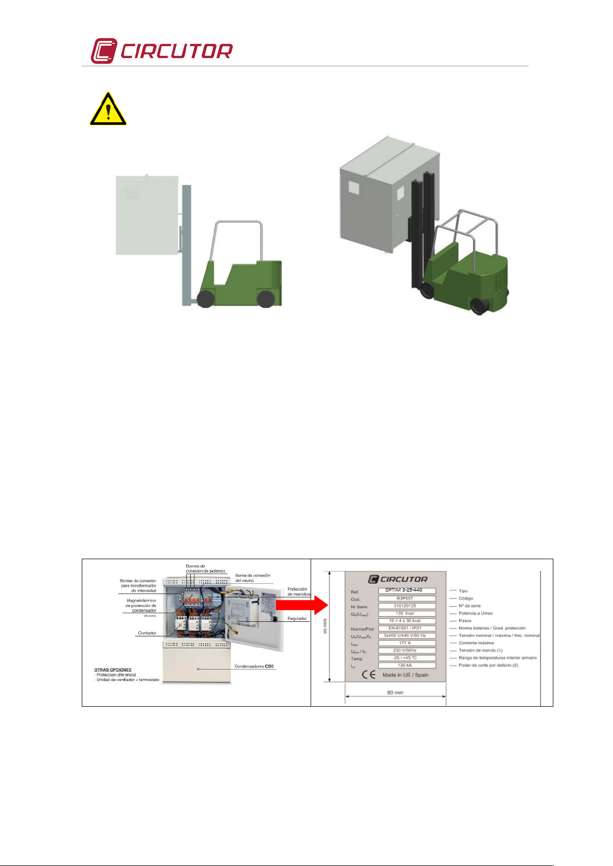
In order to move th e equip ment a s hort distance , the unit's floor support pr ofiles facilitate h andling
with a pallet jack or forklift.
with a firm and level floor and the storage conditions listed in the technical
features section must be followed. In this case, it is recommended that the
equipment be stored with its original protective packaging.
Therefore, when hand ling with a fork lift, it is recommended th at the equipm ent
be securely fastened and that no abrupt manoeuvres are carried out. The
Fig. 3-1 .-Transport with pallet jack
When unloading and m oving the equipment, use a fork lift with forks long enough to support the
entire length of the base. O therwise, the forks s hould be long enough to s upport at least ¾ of said
depth. The forks mus t be flat and must be laid firmly on the base. T he cabinet must be raised b y
placing the forks underneath the profile that supports the equipment. (Fig.3-2).
5
Page 6
OPTIM SERIES
As regards the distr ibution of loads within the equipment, its centre of gravit y may
be taken to prevent the equipment from tipping over during abrupt movements.
be displaced from the centre of the cabinet. T he necessary precautions mus t
Fig. 3-2 .-Unloading with a F orklift
3.3 Storage
The following storage recommendations shall be followed for the capacitor bank:
- Avoid placing it over irregular surfaces.
- Do not store in outdoor areas, humid areas or areas exposed to projected water.
- Avoid hot spots (maximum environmental temperature: 45 ºC)
- Avoid saline and corrosive environments.
- Avoid s toring the equ ipment in areas where a lot of dust is ge nerated or where the risk of
chemical or other types of contamination is present.
- Do not place any weight on top of the equipment cabinets.
4 TECHNICAL FEATURES
4.1 Label with the unit's features
The label with all t he equipm ent f eatures is locat ed inside t he equipm ent, gener ally nex t to the P F
regulator (refer to Fig. 4-1)
Fig. 4-1.- Label with the unit's features
6
Page 7

OPTIM SERIES
Dimensions (mm)
(kg)
OPTIM 3
290
464
170
33
OPTIM 3A
335
560
170
37
OPTIM 4
460
930
230
68
OPTIM 6
615
1330
400
87
OPTIM 12
1180
1340
360
155
OPTIM 8
1180
1650
360
260
4.2 Electrical features
- Operating voltage and nominal frequency: U
- Design voltage: U
- Nominal power and distribution of steps: Q
/ f , listed on the label
n
+ 10% (440 V for 400 V equipment)
n
and make-up, listed on the label
n
- Total loss: Less than 0.5 W/kvar
- Residual dis char g e voltage: 75 V after 3 minutes
- Overload capacity: 1.3 I
- Contactor operating voltage: U
NOTE: In general, use a 1.5 mm2 cable to supply external power.
If “Internal”, is marked, this circuit does not require external power.
-
Current transformer Input: 5 A, (I
NOT E : Minim um c able section 2.5 mm
in all items
n
, listed on the label.
aux
/5A transformer)
n
2
.
- Compliance with Standards UNE EN 61921
- Capacitor characteristics:
Capacity tolerance: ± 10%
Insulation level: 3 kV /50 Hz
Impulse test: 15 kV , 1.2/50 µs type wave
Protection elements: Internal fuses and over-pressure system
Compliance with Standards UNE EN 60831
4.3 Environmental Characteristics
- Capacitor max. temperature Category C in accordance with EN 60831-1
Maximum for 1h 50 ºC
24h average 40 ºC
A nnual average 30 ºC
- Ventilation For T
exterior > 30 ºC, the cabinet requires
amb
ventilation
- Maximum relative humidity: 80%
- Altitude: 1000 m (For higher altitudes, always maintain ventilation)
4.4 Mechanical characteristics
- Protect ion degr ee: Marked on the label:
- Paint Oven dried epoxy type
- Standard colours RAL 7035 Grey ; RAL 3005 Maroon
4.5 External dimensions and weights.
Model
Width
height (*)
Depth
Max.
Weight
7
Fig. 4-2 .- Dimensions
OPTIM SC8
OPTIM SC12
OPTIM SC16
1180
1930
2360
1805
1805
1805
460
460
460
305
585
605
Page 8

OPTIM SERIES
4.6 Capacitor bank components
Fig. 4-3 shows the different capacitor bank models and their essential components. Note that
some protection elements are optional
OPTIM 3 / OPTIM 3A
OPTIM 6 / OPTIM 12
OPTIM 4
OPTIM 8
OPTIM SC8 / OPTIM SC12 /
OPTIM SC16 ( 2 x OPTIM SC8)
8
Page 9

OPTIM SERIES
Check that the nominal voltage of the capacitor bank coincides with the voltage
For feeding cables into the capacitor bank cabinet, always use the entry points
Fig. 4-3.- Parts of the different types of banks.
(Note: Some of the protections are
optional)
5 Installation
5.1 Preparation
The CIRCUTOR capacitor banks are prepared for an easy installation and start-up.
Remove the equipment's packaging and verify that the unit's electrical characteristics are
suitable for connect ion to the available grid. To accomplish this, check the characteristics labe l
located inside the cab inet, nex t to the r egulator, r efer to Fig . 4-1, for an exam ple. Ke y data to b e
checked:
- Grid voltage and mains frequency, U
- Nominal power of the capacitor bank, Q
- Current c onsumption, I
(s ee label). This current m ust be taken into account in order to
n
/ f.
n
(kvar) and composition
n
select the proper s ize of the equipment's power sup ply cable and eventually, the circu it
breakers that are to be connected before it.
- Auxiliary control voltage, U
(See section 5.3.3)
aux
- Environmental conditions. (See section 4.3)
5.2 Installation location
It is important to keep a certain distance around the equipment clear of any items in order to
facilitate cooling. In s elf -supporting cabinets, th e back and front sides of the c ab in et must be kept
at least 50 cm away from walls and other equipment in order to f acilitate coolin g. Regarding the
sides, it is recommended that a separation of 10 c m be maintained betwe en a dj acent e quipment.
On wall mounted ca binets, it is recommended t hat at least 20 cm of separation be maintained
between the sides of adjacent equipment.
Make sure the equipment can be accessed easily.
The environmental co nditions of the locati on where the equipm ent is installed m ust not surpass
the limits established in the technical features (See section 4.3)
In order to ensure proper ventilation, the unit must be installed in a vertical position..
in accordance with L VR, on ce t he un it is ins t al led, it m us t be pr otec t ed aga ins t dir ec t and i ndir ec t
contacts; therefore, a circuit-breaker and an earth leakage protection for the capacitor bank's
power supply line should be installed.
5.3 Connection of the capacitor bank to the grid
between phases of the grid wher e it is being connected. Also check the oper ating
circuit voltage (contactors). Regarding this issue, refer to section
9
5.3.3
Page 10

OPTIM SERIES
available for this purpose.
Do not drill holes into the cabinet for feeding cables through them or for installing
support brackets. Drill ing produces metal shavings that may enter the contactor s or
other devices and cause short-circuits.
5.3.1 Power circuit.
- Connec t input term inals L1, L2 a nd L3 (pow er circuit) to the grid us ing proper s ized cable
in accordance with the L VR, ITC-BT-19. Gener ally, the cables of the three pha ses follow
the following colour code : L1 (blac k), L2 ( brown), L3 (gr ey). If auxil iary voltage is required,
the neutral cable will be connected to N (colour blue, refer to section 4.9.3)
- In order t o determine the size of the phas e cables, the nominal curre nt I
must be tak en
n
into account, which is indicat ed on the equ ipment lab el and it sho uld be able t o withstand
an overload in transients of 1.5 times I
. The neutral cable will be a minimum of 1.5 mm2
n
10
Page 11

OPTIM SERIES
autotransformer
Fig. 5-2 .- Auxiliary power supply with neutral
5.3.2 Isolation and external protection items
- In the case tha t t he cap ac it or bank does not ha ve a n i nternal switch or isolation s w itch, th e
capacitor bank must be connected to a line that has a switch or external isolation switch.
The protection elements, isolation switches and/or switches that are added
externally to the capacitor bank must be of a minimum size to withstand a
current 1.5 times greater than what is indicated on the label (REBT, ITC-BT-
48)
In the case that an earth leakage detector for the capacitor bank is installed, its
sensitivity and trip delay must be adjustable.
- When the bank is connected to t he grid, it is recommended that the current tr ansformer
(CT) is placed on the phase going to L1 ( black cable).outputs S1 and S2 of the CT must
be connected to the terminals with the same name
5.3.3 Auxiliary control voltage.
Control circuits are defined as those related with regulator output relays and the capacitor's
operating contactors. T hese circuits are usually fed to a 230 Vac auxiliary circuit(most common
case) or other voltages such as 1 10 Vac (comm on in the case of capacitor bank s at 500 v or 690
V). There are two possible ways of feeding the circuit
• Bank with auxiliary voltage obtained from an internal AUTOTRANSFORMER
Does not require connection of the external neutral. The label indicates U
/f … internal
aux
• Bank with auxiliary voltage obtained between PHASE-NEUTRAL
Requires connecting the external neutral to terminal N (see
Fig. 5-2 and Fig. 5-4 The label indicates U
Fig. 5-1 .- Auxiliary power supply with
/f … (control voltage)
aux
11
Page 12

OPTIM SERIES
A current transformer (CT) that is e xternal to the bank must be installed to
bank.
5.3.4 Earth cable connection
Connect the earth cable t o the capac itor bank 's earth term inal located on the equi pment oper ating
panel. The cable size w ill be selecte d in accordanc e with the adm issible current limits es tablished
in the REBT (ITC-BT-19 – Internal or receiver installations) for each type of cable and their
location.
5.3.5 Connecting the current transformer (CT)
measuring the total load current plus the bank (see Fig. 5-3).
The standard transformer has a nominal output of 5 A at the secondary winding.
It is recommended to connect the CT to phase L1 in the direction of the current
flow from P1 to P2 (see Fig. 5-3) and connect the secondary winding (terminals
S1, S2) to the terminals with the same name on the bank (see Fig. 5-3).
Avoid current flow through the CT primary winding prior to connecting it to
terminals S1 S2 of the bank. If the CT must be installed while recharging the
installation, short-circuit S1 and S2 as long as they are not connected to the
• The current value of the CT pr imary winding m ust be equal or som ewhat greater than the size
of the installation's mains switch. Therefore, the CT must be able to measure the m aximum
current that is foreseen will be consumed by all the loads to be compensated.
Fig. 5-3 .- Installation of the current transformer (CT) (external)
• The connection point of the CT for a bank that compensates an entire installati on is after the
installation's mains switch.
• To prevent excessive attenuation of the signal, the minimum secondary winding cable size
(terminals S1, S2) is recommended to be at least 2.5 mm
Fig. 5-4.- CT and neutral connection terminals if required
12
2
.
Page 13

OPTIM SERIES
During low charge periods, manually connecting the entire bank is not
recommended, as in some cases resonance with the installation power
with a voltage of up to 2xUn causing destruction of the capacitor.
Safety
k is
installed or operated should be strictly followed.
• Once the cables are install ed, disconnect the jumper connecti ng terminals S1 and S2 of the
bank (seer Fig. 5-5)
Fig. 5-5.- Jumper for short-circuiting the secondary winding of the current transformer (CT).
Any time you wish to change or disconnect a current transformer that is already
installed, it is important to install the jumper connecting S1 and S2.
6 CAPACITOR BANK START-UP
6.1 Before start-up
The automatic capacitor banks include a power factor regul ator. Prior to start -up, the operation of
said regulator mus t be known; for this reason, all the banks incorporate a specific manual of the
regulator used. Ensure you have this manual available for the start-up process.
In order to carry out the adj ustment of the regulator incorpor ated to the capacitor
bank and carry out an optimum start-up, requires the charge of th e installation be
at least 30% or 40% of the nominal charge the bank has been sized for. In the
case that all the stages are not include d, the y ma y be manuall y connecte d in ord er
to check them all.
transformer could occur.
the capacitors are connected in manual mode, first allow enough time for the
capacitors to discharge (as indicated in the bank's specifications tag) before
reconnecting them to the power grid. Otherwise, the y could start-up out of p hase
6.2 Start-up
Apply the safet y regulations listed in sect ion 2 of this manual before operating the
equipment.
The standards and applicable laws of the country where the capacitor ban
13
Page 14

OPTIM SERIES
• Ensure the inner circuit break er that starts the regulator (shown as the operating protection in
fig. 4.3) is connected
• Apply power to the panel and check that the regulator display illuminates immediately.
Otherwise, stop and check the previous step.
• Check the regulator's cos ϕ indication. If the indication is out of range 0.5 to 1, it may be
possible that the current tr ansformer and / or the power suppl y to the regulator ar e improperly
connected. Most of the r egulators use only one current tr ansformer. In this case, connect as
per fig. 6-2 (place the current transformer on phase L1 and take the power voltage from
phases L2 and L3)
Fig. 6- 1.-
(picture provided as an example. It may not
coincide with the model used on your unit).
computer Max regulator
Fig. 6-2 .-
(If using computer Plus, 3 current transformers are used. Refer to the
Type connection of a regulator with only one CT
computer Plus specific manual)
• Once ensured that the regulator is properl y connecte d, adjust th e regulator param eters for t he
installation you are attempting to compensate. To accomplish this, follow the regulator's
instructions manual included with the battery.
6.3 Checks once the bank is connected and the regulator has been adjusted
• After start-up, make sure that the e quipment is operating c orrectly. A sign of pr oper operation
is a cos ϕ next to a 1 indicated on the display. In addition, the reactive meter must stop.
• Check that the power supply voltag e does not go above the nom inal value +10% ( IEC 60831-
1)
• Check the current absorbed b y each capacitor. Under normal conditions, i t must be close to
the nominal value indicate d on its characteristics plat e and never exceed 1.3 tim es this value
constantly.A continuo us consum ption over the nominal val ue may be caus ed by the prese nce
of harmonics in the grid or an excessivel y high power supply volta ge. Both cir cumstances ar e
harmful for capacitors.
• In accordance with the IEC 60831-1 Standard, the capacitor is prepared to operate
continuously at up to 10% overvoltage for up to 8 hours, every 24 hours.
Check the working tem perature of the capacitors after they have been operati ng
for 24 hours. The capsule must be below 40 ºC
14
Page 15

OPTIM SERIES
SAFETY
installed or operated should be strictly followed.
FUSE BASE
TORQUE (Nm)
NEOZED 63 A
3.6
NH-00
15.2
7 MAINTENANCE
7.1 Safety regulation
Apply the safet y regulations listed in sect ion 2 of this manual before operating the
equipment.
The standards and applicable laws of the country where the capacitor bank is
7.2 Maintenance with the bank disconn ected
7.2.1 Basic maintenance protocol
Monthly
• Perform a visual inspection of the capacitors
• Check the protection fuses
• Control the environmental temperature (average of 30 ºC. In accordance with IEC 60831).
• Control the service volt age (especially duri ng moments of low ch arge, it must not ex ceed the
nominal +10%).
Six-monthly
• Maintain the capacitor terminals clean.
• Verify the state of the contacts of operating elements.
• Check that the capacitor curr ent is not lower than 25% or greater than 12 0% of the nominal
value by phase and that there is no phase unbalance greater than 15%.
Annually
• Carry out a dielectric rigidity test by applying 2.5 kV for 1 s between the c apacitor's terminals
and earth.
• Check the capacity of the different steps. One indirect check may be to check that the
consumption is manual.
• Check the tightness of all terminal connections.
• Inspection of the fuses.
- Power circuit: NH fuses. Check continuity and temperature.
- Control Circuit: Neozed fuses. Check continuity and temperature
7.2.2 Tightening the electrical connec tions.
• The connections must be tight. The following tightening torques for the fuse bases and
contactors are listed in tables 7-1 and 7-2
Table 7-1.- Tightening torques of the cables to the fuse bases
15
Page 16

OPTIM SERIES
MODEL
Auxiliary (Nm)
POWER (Nm)
MC-12
1.3
1.6
MC-18
1.3
2.2
MC-32
1.3
2.9
MC-40
1.3
2.9
MC-50
1.3
4.5
MC-65
1.3
4.5
MC-75
1.3
4.5
MC-85
1.3
4.5
MC-150
1.3
9
Table 7-2.- Tightening torques of the cables to contactor terminals
7.2.3 Key points for inspecting contactors.
• Check that the plastic parts are not blackened and do not show signs of burning or hardening.
• Check that the head is properly inserted
• Check the tightness of cables and terminals, as shown on table 7-2
• The terminals must be clean.
• In the case that the bank includes RD discharge resistors, check they are in good cond ition
(they are not open or show signs of burning).
Fig. 7-1.-
Connection of the discharge resistors
• Cleaning the contactors: In dirt y environments ( dust, sawdust, rust part icles, etc.) vacuum the
contactor periodically. There is no estimated time frame for cleaning, it depends on the amount
of dirt that is inside the bank.
7.2.4 Key points for inspecting capacitors.
• Inspect the cables and terminals. They should not be overheated or blackened.
• The terminals must be clean.
• The slow discharge resistor m ust be in good con ditio n (the y shou ld not b e open or s how signs
of burns)
• Check the tightness of capacitor terminals, as shown on table 7-3
16
Page 17

OPTIM SERIES
(Nm)
(Nm)
CSB
21
6.2
CLZ CAPACITORS
(Nm)
(Nm)
2.5
0.33
0.463 3 0.57
0.8 4 1.3
1.83 5 2.59
3.62 6 4.49
6.2 8 10.9
15.2
10
21
30
12
37
50
Table 7-3.- Tightening torques of the cables on the capacitor bank terminals
Capacitor
Power terminal
Earth terminal
Diameter (mm)
Power terminal
Earth terminal
7.2.5 Key points for inspecting the regu lator
• Check that the regulator does not show signs of deterioration and the display is lit as normal.
• Inspect the cables and terminals. They should be clean and should not be hardened or
overheated.
• Inspect the connections and the insertion of removable terminal strips:
- The terminal strips must be well fastened on removable regulators.
- Check that the terminals are tightened properly. The recommended torque is 0.6 Nm.
7.2.8 Cleaning the cabinet.
• Remove possible metallic and non-metallic par ticles.
• Clean the inside of the cabinet
• Clean ventilation grilles
7.3 Maintenance with the battery connec ted.
• Check that the mains switch connects and disconnects, without having to force the mechanism
• If there is an individual earth leakage protection for the bank , check its proper operation by
pressing the test button.
• Check that the auxiliary control voltage is within the tolerance limits. If the bank has an
autotransformer, check it is in good condition and does not show signs of deterioration.
• Force the connection and disconnection of the capacitors in manual mode.(refer to the
regulator manual before carrying out this action) and perform the following checks:
- Check that the contactors connect and disconnect properly.
- Check that the contactor, once connected, does not rattle or vibrate.
- Check the capacitor consumption in each of the phases. The normal values are provided
in table 7-4
17
Page 18

OPTIM SERIES
CURRENT
230 V
400 V
In
In
2.5 kvar
6.28 A
3.6 A
5 kvar
12.56 A
7.2 A
7.5 kvar
18.85 A
10.8 A
10 kvar
25.12 A
14.4 A
12.5 kvar
31.41 A
18 A
15 kvar
37.7 A
21.6 A
20 kvar
50.24 A
28.8 A
25 kvar
62.82 A
36 A
30 kvar
75.4 A
43.2 A
40 kvar
100.48 A
57.6 A
50 kvar
125.64 A
72 A
60 kvar
150.8 A
86.4 A
70 kvar
175.92 A
101.1 A
80 kvar
200.96 A
115 A
Table 7-4.- Nominal consumption of the capacitors, according to the power
Power
NOTE: If the consumption is below ±25%, and the voltage is normal, this is usually a symptom of
degradation of the capacitors. In case this is detected in a capacitor, it should be replaced with
another capacitor.
7.3.3 Regulator Checks.
Refer to the manual of the specific regulator used in the batter y. This manual is
always supplied with the bank.
• Check that there are no faulty segments on the display.
• Check that the keyboard is operating properly:
- Enter Setup and check the adjusted values
- Force the manual connection and disconnection of a step.
7.4 Environmental Conditions:
• Check that the maximum environmental conditions listed in section 4.3 are observed
18
Page 19

OPTIM SERIES
8 GUARANTEE,
CIRCUTOR guarantees its products against any manufacturing defect for two years after the
delivery of the equipment.
CIRCUTOR will repair or replace any defective factory product returned during the guarantee
period.
No returns will be accepte d and no unit will be repaired or replaced if it is not accompanied by a
report indicating the defect detected or the reason for the return.
The guarantee will be void if the equipm ent has been impr operly used or the stor age, installation
and maintenance instructions listed in this manual have not been followed. "Improper usage" is
defined as any operating or storage condition that is not in compliance with LV Regulations or
surpassing the limits indicated in the technical and environmental features of this manual.
In particular, capacitor units are very sensitive to adverse environmental conditions, to
temperatures above t he established limits and over loads produced by the absorption of harm onic
currents. Therefore, special care must be taken to not surpass these usage conditions.
CIRCUTOR accepts no liability due to the possible damage to equipment or other parts of the
installation, nor will it cover any possible sanctions derived from a possible failure, improper
installation or "improper usage" of the equipment.
Consequently, this guarantee does not apply to failures occurred in the following cases:
1. Over
2. voltages and/or electrical disturbances in the supply;
3. Water, if the product does not have the appropriate IP classification;
4. Poor ventilation and/or excessive temperatures;
5. Improper installation and/or lack of maintenance;
6. Buyer repairs or modifications without the manufacturer's authorisation.
9 TECHNICAL ASSISTANCE AND DECLARATION OF CONFORMITY
CIRCUTOR provides ad vice and technical assistance s ervices throughout Spain for the planning
and installation of capacitors, automatic power factor correction equipment and harmonics filters.
CIRCUTOR, SA
Vial Sant Jordi, s/n – 08232 – Viladecavalls (Barcelona)
S.A.T.:902 449 459 (Spain) Tel. +34 93 745 29 00 (all other countries)
Fax: +34 93 745 29 14
Web: www.circutor.com – email: sat@circutor.es
19
Page 20

OPTIM SERIES
Declaration of conformity
20
 Loading...