

Page 1
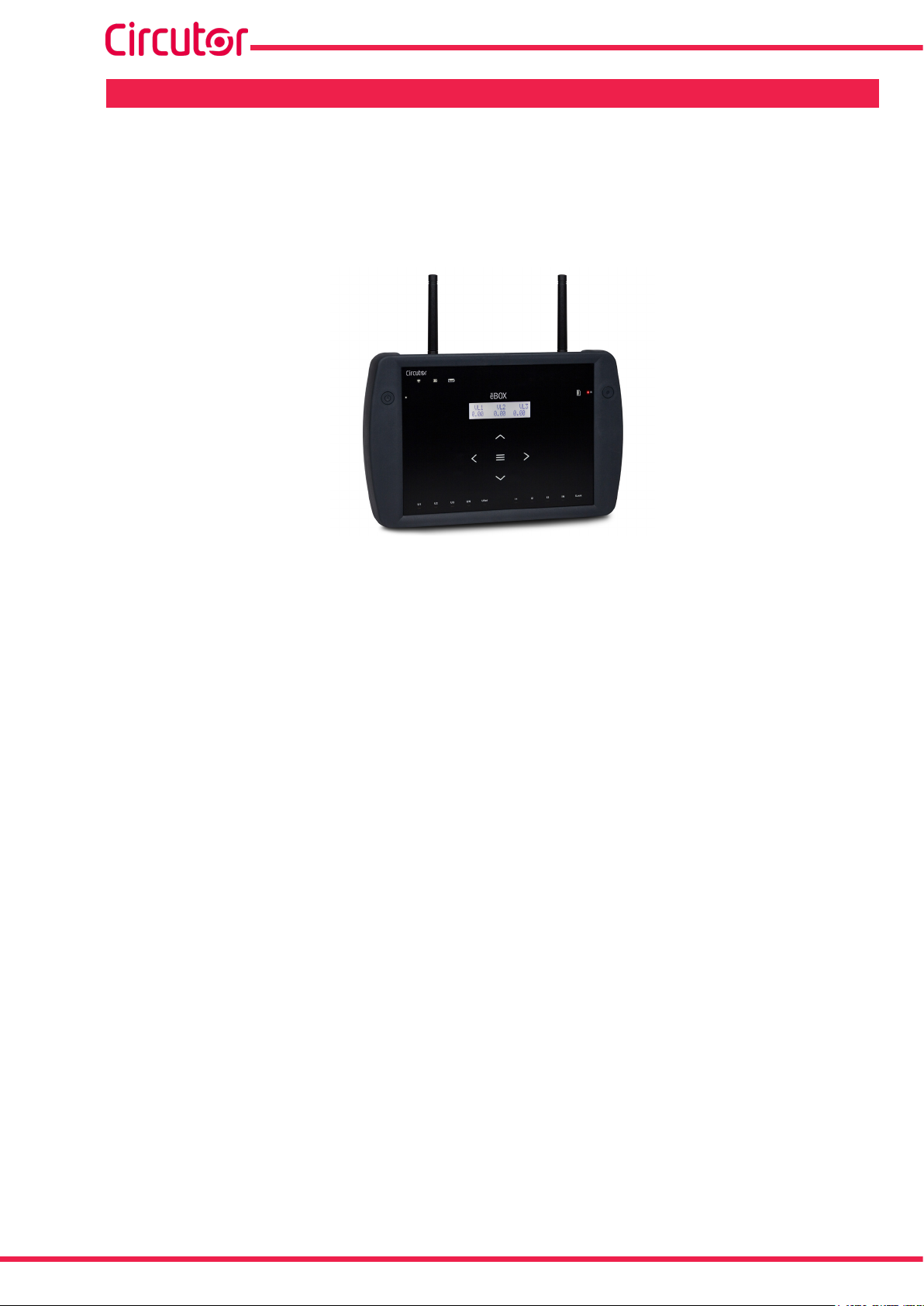
Portable power analyzer
MYeBOX 150, MYeBOX 1500
INSTRUCTION MANUAL
(M084B01-03-19A)
MEASURING EQUIPMENT
E237816
Page 2

MYeBOX 150 - MYeBOX 1500
2
Instruction Manual
Page 3
MYeBOX 150 - MYeBOX 1500
SAFETY PRECAUTIONS
Follow the warnings described in this manual with the symbols shown below.
DANGER
Warns of a risk, which could result in personal injury or material damage.
ATTENTION
Indicates that special attention should be paid to a speci c point.
If you must handle the unit for its installation, start-up or maintenance, the following
should be taken into consideration:
Incorrect handling or installation of the unit may result in injury to personnel as well as damage
to the unit. In particular, handling with voltages applied may result in electric shock, which may
cause death or serious injury to personnel. Defective installation or maintenance may also
lead to the risk of re.
Read the manual carefully prior to connecting the unit. Follow all installation and maintenance
instructions throughout the unit’s working life. Pay special attention to the installation standards of the National Electrical Code.
Refer to the instruction manual before using the unit
In this manual, if the instructions marked with this symbol are not respected or carried out correctly, it can
result in injury or damage to the unit and /or installations.
CIRCUTOR, SA reserves the right to modify features or the product manual without prior noti cation.
DISCLAIMER
CIRCUTOR, SA reserves the right to make modi cations to the device or the unit speci ca-
tions set out in this instruction manual without prior notice.
CIRCUTOR, SA on its web site, supplies its customers with the latest versions of the device
speci cations and the most updated manuals.
www.circutor.com
CIRCUTOR, recommends using the original cables and accessories that are
supplied with the device.
Instruction Manual
3
Page 4

MYeBOX 150 - MYeBOX 1500
CONTENTS
SAFETY PRECAUTIONS ���������������������������������������������������������������������������������������������������������������������������������������3
DISCLAIMER ����������������������������������������������������������������������������������������������������������������������������������������������������������3
CONTENTS ������������������������������������������������������������������������������������������������������������������������������������������������������������� 4
REVISION LOG ������������������������������������������������������������������������������������������������������������������������������������������������������� 6
SYMBOLS ��������������������������������������������������������������������������������������������������������������������������������������������������������������� 6
1�- VERIFICATION UPON RECEPTION ����������������������������������������������������������������������������������������������������������������� 7
2�- PRODUCT DESCRIPTION �������������������������������������������������������������������������������������������������������������������������������� 8
3�- DEVICE INSTALLATION ���������������������������������������������������������������������������������������������������������������������������������10
3�1�- PRELIMINARY RECOMMENDATIONS ���������������������������������������������������������������������������������������������������10
3�2�- BATTERY INSTALLATION ����������������������������������������������������������������������������������������������������������������������� 11
3�3�- INSTALLATION ����������������������������������������������������������������������������������������������������������������������������������������13
3�3�1�- MAGNETIC FASTENING STRAP ���������������������������������������������������������������������������������������������������13
3�4�- MYeBOX 480V ~ PSU ADAPTER : POWER SUPPLY ADAPTER ����������������������������������������������������������14
3�5�- VOLTAGE CABLES ����������������������������������������������������������������������������������������������������������������������������������16
3�6�- CURRENT CLAMPS ��������������������������������������������������������������������������������������������������������������������������������16
3�7�- DEVICE TERMINALS ������������������������������������������������������������������������������������������������������������������������������� 17
3�7�1�- MYeBOX 150 ������������������������������������������������������������������������������������������������������������������������������������� 17
3�7�2�- MYeBOX 1500 ����������������������������������������������������������������������������������������������������������������������������������� 18
3�8�- CONNECTION DIAGRAMS ��������������������������������������������������������������������������������������������������������������������20
3�8�1�- THREE-PHASE NETWORK MEASURING WITH A 4-WIRE CONNECTION, MYeBOX 150� ���������20
3�8�2�- THREE-PHASE NETWORK MEASURING WITH A 4-WIRE CONNECTION, MYeBOX 1500� �������21
3�8�3�- THREE-PHASE NETWORK MEASURING WITH A 3-WIRE CONNECTION, MYeBOX 150 AND
MYeBOX1500� ��������������������������������������������������������������������������������������������������������������������������������������������� 22
3�8�4�- THREE-PHASE NETWORK MEASURING WITH A 3-WIRE CONNECTION AND ARON CONNEC-
TION, MYeBOX 150 AND MYeBOX 1500� ��������������������������������������������������������������������������������������������������23
3�8�5�- TWO-PHASE NETWORK MEASURING WITH A 3-WIRE CONNECTION MYeBOX 150� ��������������24
3�8�6�- TWO-PHASE NETWORK MEASURING WITH A 3-WIRE CONNECTION MYeBOX 1500� ������������25
3�8�7� - SINGLE-PHASE NETWORK MEASUREMENT, PHASE TO PHASE, WITH A 2-WIRE CONNEC-
TION, MYeBOX 150 AND MYeBOX 1500� ���������������������������������������������������������������������������������������������������26
3�8�8�- SINGLE-PHASE NETWORK MEASUREMENT, PHASE TO NEUTRAL, WITH A 2-WIRE CONNEC-
TION, MYeBOX 150� ������������������������������������������������������������������������������������������������������������������������������������� 27
3�8�9�- SINGLE-PHASE NETWORK MEASUREMENT, PHASE TO NEUTRAL, WITH A 2-WIRE CONNEC-
TION, MYeBOX 1500� ����������������������������������������������������������������������������������������������������������������������������������� 28
3�8�10�- DETAIL OF THE CURRENT MEASUREMENT CONNECTION� ����������������������������������������������������29
3�8�11�- LEAKAGE CURRENT CONNECTION, ILeak� (MYeBOX 1500 MODEL) ��������������������������������������29
3�9�- REGISTERING AND UPDATING THE DEVICE �������������������������������������������������������������������������������������� 30
4�- OPERATION ���������������������������������������������������������������������������������������������������������������������������������������������������31
4�1�- OPERATING PRINCIPLE ������������������������������������������������������������������������������������������������������������������������ 31
4�2�- MEASUREMENT PARAMETERS ����������������������������������������������������������������������������������������������������������� 32
4�2�1�- QUALITY PARAMETERS������������������������������������������������������������������������������������������������������������������33
4�3�- KEYPAD FUNCTIONS������������������������������������������������������������������������������������������������������������������������������35
4�4�- DISPLAY ���������������������������������������������������������������������������������������������������������������������������������������������������36
4�5�- LED INDICATORS ������������������������������������������������������������������������������������������������������������������������������������ 37
4�5�1�- MYeBOX 150� ������������������������������������������������������������������������������������������������������������������������������������ 37
4�5�2�- MYeBOX 1500� ���������������������������������������������������������������������������������������������������������������������������������� 39
4�6�- INPUTS (MYeBOX 1500 model) �������������������������������������������������������������������������������������������������������������41
4�7�- OUTPUTS (MYeBOX 1500 model) ���������������������������������������������������������������������������������������������������������41
4�8�- DATA LOGGING ��������������������������������������������������������������������������������������������������������������������������������������� 42
4�8�1� DATABASE �����������������������������������������������������������������������������������������������������������������������������������������42
4�8�2� MicroSD MEMORY ����������������������������������������������������������������������������������������������������������������������������� 42
5�- DISPLAY ���������������������������������������������������������������������������������������������������������������������������������������������������������49
5�1�- DISPLAY MENU: MEASURE �������������������������������������������������������������������������������������������������������������������51
5�2�- DISPLAY MENU: DEVICE PROFILE �������������������������������������������������������������������������������������������������������53
5�3�- DISPLAY MENU: QUALITY����������������������������������������������������������������������������������������������������������������������54
5�4�- DISPLAY MENU: COMMUNICATIONS ���������������������������������������������������������������������������������������������������� 55
5�5�- DISPLAY MENU: DATE/TIME ������������������������������������������������������������������������������������������������������������������ 56
5�6�- DISPLAY MENU: INFORMATION ������������������������������������������������������������������������������������������������������������ 57
5�7�- DISPLAY MENU: ENERGY RATIOS ������������������������������������������������������������������������������������������������������� 58
6�- CONFIGURATION �������������������������������������������������������������������������������������������������������������������������������������������60
4
Instruction Manual
Page 5

MYeBOX 150 - MYeBOX 1500
6�1�- SETUP MENU: MEASURE SETUP ��������������������������������������������������������������������������������������������������������� 61
6�1�1�- RATED VOLTAGE �����������������������������������������������������������������������������������������������������������������������������61
6�1�2�- PRIMARY VOLTAGE ������������������������������������������������������������������������������������������������������������������������� 62
6�1�3�- SECONDARY VOLTAGE�������������������������������������������������������������������������������������������������������������������62
6�1�4�- PHASE CLAMP SCALE ������������������������������������������������������������������������������������������������������������������� 63
6�1�5�- PRIMARY WINDING OF THE CURRENT TRANSFORMER �����������������������������������������������������������63
6�1�6�- NEUTRAL CLAMP SCALE �������������������������������������������������������������������������������������������������������������64
6�1�7�- PRIMARY WINDING OF THE NEUTRAL CURRENT TRANSFORMER ����������������������������������������� 64
6�1�8�- CLAMP SCALE FOR MEASURING THE LEAKAGE CURRENT, ILeak �����������������������������������������65
6�1�9�- PRIMARY WINDING OF THE LEAKAGE CURRENT TRANSFORMER �����������������������������������������65
6�1�10�- FREQUENCY ����������������������������������������������������������������������������������������������������������������������������������� 66
6�1�11�- SAVE ������������������������������������������������������������������������������������������������������������������������������������������������ 66
6�1�12�- EXIT �������������������������������������������������������������������������������������������������������������������������������������������������66
6�2�- SETUP MENU: DEVICE PROFILE SETUP ��������������������������������������������������������������������������������������������� 67
6�2�1�- NAME OF THE DEVICE �������������������������������������������������������������������������������������������������������������������� 67
6�2�2�- MEASUREMENT NAME �������������������������������������������������������������������������������������������������������������������67
6�2�3�- TYPE OF INSTALLATION �����������������������������������������������������������������������������������������������������������������68
6�2�4�- SAVE �������������������������������������������������������������������������������������������������������������������������������������������������� 68
6�2�5�- EXIT ���������������������������������������������������������������������������������������������������������������������������������������������������68
6�3�- SETUP MENU: QUALITY SETUP �����������������������������������������������������������������������������������������������������������69
6�3�1�- OVERVOLTAGE, SWELL ������������������������������������������������������������������������������������������������������������������ 69
6�3�2�- GAP, SAG ������������������������������������������������������������������������������������������������������������������������������������������ 69
6�3�3�- OUTAGE, INTERRUPTION ��������������������������������������������������������������������������������������������������������������� 70
6�3�4�- TRANSIENTS, DISTURB ������������������������������������������������������������������������������������������������������������������70
6�3�5�- SAVE �������������������������������������������������������������������������������������������������������������������������������������������������� 71
6�3�6�- EXIT ���������������������������������������������������������������������������������������������������������������������������������������������������71
6�4�- SETUP MENU: COMMUNICATIONS SETUP ������������������������������������������������������������������������������������������ 71
6�4�1�- Wi-Fi CONFIGURATION ������������������������������������������������������������������������������������������������������������������� 71
6�4�2�- SSID ��������������������������������������������������������������������������������������������������������������������������������������������������� 72
6�4�3�- WPS ��������������������������������������������������������������������������������������������������������������������������������������������������� 72
6�4�4�- PASSWORD �������������������������������������������������������������������������������������������������������������������������������������� 73
6�4�5�- ENABLING 3G COMMUNICATIONS ������������������������������������������������������������������������������������������������ 73
6�4�6�- APN, ACCESS POINT NAME �����������������������������������������������������������������������������������������������������������74
6�4�7�- APN, USER ���������������������������������������������������������������������������������������������������������������������������������������� 74
6�4�8�- APN, PASSWORD �����������������������������������������������������������������������������������������������������������������������������75
6�4�9�- PIN ����������������������������������������������������������������������������������������������������������������������������������������������������75
6�4�10�- SAVE ������������������������������������������������������������������������������������������������������������������������������������������������ 76
6�4�11�- EXIT ������������������������������������������������������������������������������������������������������������������������������������������������� 76
6�5�- SETUP MENU: MEMORY SETUP ����������������������������������������������������������������������������������������������������������� 76
6�5�1�- COMPLETE DELETION OF THE DATABASE ���������������������������������������������������������������������������������76
6�5�2�- SAVE �������������������������������������������������������������������������������������������������������������������������������������������������� 77
6�5�3�- EXIT ���������������������������������������������������������������������������������������������������������������������������������������������������77
6�6�- SETUP MENU: RESET FACTORY SETUP ���������������������������������������������������������������������������������������������78
6�6�1�- LOADING THE DEFAULT CONFIGURATION� ��������������������������������������������������������������������������������� 78
6�6�2�- SAVE �������������������������������������������������������������������������������������������������������������������������������������������������� 78
6�6�3�- EXIT ���������������������������������������������������������������������������������������������������������������������������������������������������79
7�- WIRELESS COMMUNICATIONS �������������������������������������������������������������������������������������������������������������������� 80
7�1�- USAGE ENVIRONMENT AND HEALTH �������������������������������������������������������������������������������������������������� 80
7�2�- LOCATION OF THE ANTENNAS �������������������������������������������������������������������������������������������������������������81
7�3�- Wi-Fi COMMUNICATIONS ����������������������������������������������������������������������������������������������������������������������� 81
7�4�- 3G COMMUNICATIONS (MYeBOX 1500 model) ������������������������������������������������������������������������������������ 82
7�4�1�- INSERTING THE SIM CARD� ������������������������������������������������������������������������������������������������������������82
8�- MOBILE APPLICATION MYEBOX ������������������������������������������������������������������������������������������������������������������ 83
9�- MYeBOX Cloud ����������������������������������������������������������������������������������������������������������������������������������������������� 83
10�- SOFTWARE UPDATE �����������������������������������������������������������������������������������������������������������������������������������83
10�1�- UPDATING THROUGH USB ����������������������������������������������������������������������������������������������������������������� 83
10�2�- UPDATING THROUGH THE MOBILE APPLICATION ������������������������������������������������������������������������� 84
11�- TECHNICAL FEATURES �������������������������������������������������������������������������������������������������������������������������������85
12�- MAINTENANCE AND TECHNICAL SERVICE ���������������������������������������������������������������������������������������������� 89
13�- GUARANTEE �������������������������������������������������������������������������������������������������������������������������������������������������89
14�- CE CERTIFICATE ������������������������������������������������������������������������������������������������������������������������������������������ 90
Instruction Manual
5
Page 6
REVISION LOG
Date Revision Description
10/16 M084B01-03-15A Initial Version
11/16 M084B01-03-16A
10/17 M084B01-03-17A
02/18 M084B01-03-18A
06/18 M084B01-03-18B
06/19 M084B01-03-19A
MYeBOX 150 - MYeBOX 1500
Table 1: Revision log�
Changes in the following sections:
1. - 3.2. - 3.5. - 11.
Changes in the following sections:
3.2. - 3.5. - 3.8. - 4.2. - 4.2.1. - 4.5.2. - 4.8.2.3. - 5.6. - 6.1.- 6.3.4. - 11.- 14.
Changes in the following sections:
3.2.- 3.4.- 11.
Changes in the following sections:
4.2. - 4.8.2.3. - 5. - 5.1. - 5.4. - 5.7. - 6.1.1 - 7.3. - 7.4. - 11.
Changes in the following sections:
3.4. - 4.2. - 4.2.1. - 4.8.2.3. - 6.4.4. - 6.4.8. - 10. - 11.
SYMBOLS
Table 2: Symbols�
Symbol Description
In compliance with the relevant European directive.
MEASURING EQUIPMENT
E237816
~
UL certied
In compliance with the CMiM directive.
Safety category of the device : Class II
Device covered by European directive 2012/19/EC. At the end of its useful
life, do not leave the unit in a household waste container. Follow local regulations on electronic equipment recycling.
DC current
AC current
Note: The images of the devices are for illustrative purposes only and may differ from the orig-
inal device.
6
Instruction Manual
Page 7
MYeBOX 150 - MYeBOX 1500
1�- VERIFICATION UPON RECEPTION
Check the following points when you receive the device:
a) The device meets the specications described in your order.
b) The device has not suffered any damage during transport.
c) Perform an external visual inspection of the device prior to switching it on.
d) Check that it has been delivered with the following:
Kit A_MYeBOX 150 and Kit A_MYeBOX 1500:
- An installation guide.
- 1 battery.
- 1 AC power supply adaptor.
- 1 Wi-Fi antenna.
- 1 3G antenna (Kit A_MYeBOX 1500).
- 1 μUSB cable.
- MYeBOX markers in 9 colours.
- Wireless connector for the transistor's digital inputs/outputs
(Kit A_MYeBOX 1500).
Kit MYeBOX 150 and Kit MYeBOX 1500:
- An installation guide.
- 1 battery.
- 1 AC power supply adaptor.
- 1 Wi-Fi antenna.
- 1 3G antenna (Kit MYeBOX 1500).
- 1 μUSB cable.
- MYeBOX markers in 9 colours.
- 4 UL 600 V CAT III voltage cables (5 in Kit MYeBOX 1500).
- 4 UL 600 V CAT III crocodile clamp (5 in Kit MYeBOX 1500).
- Wireless connector for the transistor's digital inputs/outputs
(Kit MYeBOX 1500).
- Carrying case.
If any problem is noticed upon reception, immediately contact the transport
company and/or CIRCUTOR's after-sales service.
Instruction Manual
7
Page 8
MYeBOX 150 - MYeBOX 1500
2�- PRODUCT DESCRIPTION
MYeBOX is a portable analyzer that measures, calculates and displays the main parameters of
any electrical installation (single-phase, two-phase with and without neutral, balanced or unbalanced three-phase and through an ARON connection)
MYeBOX can be fully congured remotely and can display electrical parameters on a smart-
phone or tablet using a mobile application connected to a Wi-Fi network.
There are 2 device models:
MYeBOX 150.
MYeBOX 1500.
The MYeBOX 150 features:
- 4 inputs for measuring voltage: L1, L2, L3 and N.
- 4 inputs for measuring current: L1, L2, L3 and N.
- 5 keys and 2 buttons that allow you to browse between the various screens and pro-
gram the device.
- 14 indicator LEDs: on, battery status, log, measurement input connection, memory
status and Wi-Fi connection.
- LCD Display, for viewing parameters.
- Wi-Fi communications.
- 1 μUSB connector to connect and download data to a PC.
The MYeBOX 1500 features:
- 5 inputs for measuring voltage: L1, L2, L3, N and reference voltage URef.
- 5 inputs for measuring current: L1, L2, L3, N and leakage current.
- 5 keys and 2 buttons that allow you to browse between the various screens and pro-
gram the device.
- 21 indicator LEDs: on, battery status, log, measurement input connection, memory
status, Wi-Fi connection and 3G connection.
- LCD Display, for viewing parameters.
- 2 digital inputs.
- 2 transistor outputs�
- 3G communications.
- Wi-Fi communications.
8
Instruction Manual
Page 9

MYeBOX 150 - MYeBOX 1500
- 1 μUSB connector to connect and download data to a PC.
The MYeBOX mobile application lets you fully program the MYeBOX remotely, congure the
measurement, display the most important parameters and send logs to MYeBOX Cloud.
Instruction Manual
9
Page 10
MYeBOX 150 - MYeBOX 1500
3�- DEVICE INSTALLATION
3.1.- PRELIMINARY RECOMMENDATIONS
In order to use the device safely, it is essential that the individuals who handle it
follow the safety measures set out in the standards of the country where it is being used, use the necessary personal protective equipment (rubber gloves, facial
protection, and approved reproof clothing) to avoid injury from shocks or electric
arc from exposure to live conductors, and pay attention to the various warnings
included in this instruction manual.
The MYeBOX device must be installed by authorised and qualied staff.
The power supply plug must be disconnected and measuring systems switched off before handling, altering the connections or replacing the device. It is dangerous to handle the device
while it is powered.
Also, it is critical to keep the cables in perfect condition to avoid accidents, personal injury and
damage to installations.
The device's functionality is limited to the category of measuring voltage or specic current
values.
The manufacturer of the device is not responsible for any damage resulting from failure by the
user or installer to heed the warnings and/or recommendations set out in this manual, nor for
damage resulting from the use of products or accessories that did not come with the device or
that were made by other manufacturers.
Inspect the device prior to each use. Check that it has no cracks and no pieces are missing
from the housing.
If an anomaly or malfunction is detected in the device, do not use the device to take any measurements.
Inspect the work area before taking any measurements. Do not take measurements in dangerous, humid or wet areas or blasting areas.
Disconnect the device from the power supply (device and measuring system
power supply) before maintaining, repairing or handling the device's connections.
Please contact the after-sales service if you suspect that there is an operational
fault in the device.
10
Instruction Manual
Page 11
MYeBOX 150 - MYeBOX 1500
3.2.- BATTERY INSTALLATION
Do not disassemble or modify the battery.
The warranty does not cover any battery not delivered by Circutor or batteries
that have been disassembled or modied.
There is a risk of explosion if installed incorrectly.
To avoid possible damage:
- Only install the batteries supplied or recommended by Circutor.
- Keep the battery away from re and high-temperature lights.
- Do attempt to disassemble it.
- Do not expose it to water.
- Do not short-circuit it.
- Do not hit the battery.
When disposing of the battery, comply with local laws and ordinances.
Do not dispose of it with household waste. At the end of its useful life, dispose
of the product at a specic collection point for electrical or electronic equipment.
To avoid electric shocks, disconnect the measuring and power supply terminals
before opening the cover.
Do not use the device without the cover in place.
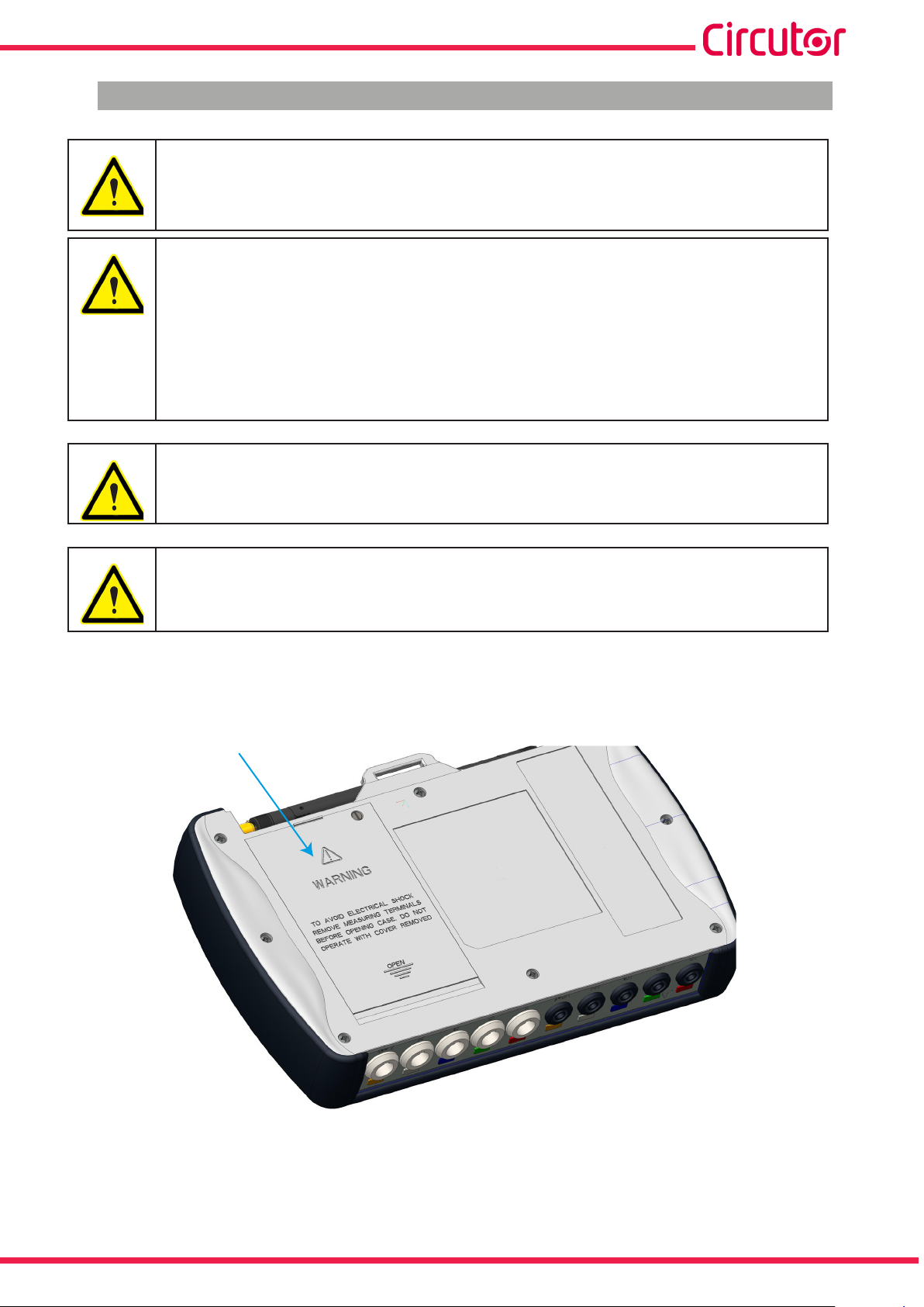
The battery's cover is located on the underside of the device, as shown in Figure 1.
Battery
Figure 1:Location of the battery�
Unscrew the cover fastening screws with a athead screwdriver and slide the cover off the device. (Figure 2)
Instruction Manual
11
Page 12
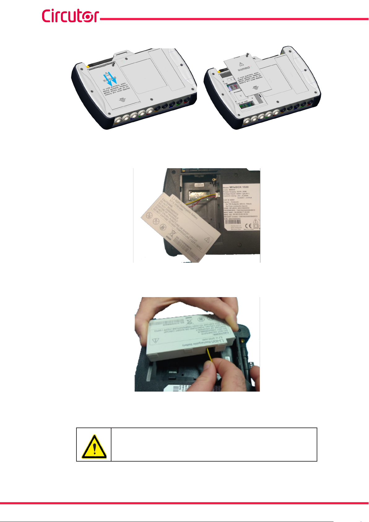
Connect the battery, Figure 3.
MYeBOX 150 - MYeBOX 1500
Figure 2:Removal of the battery cover�
Figure 3:Connect the battery�
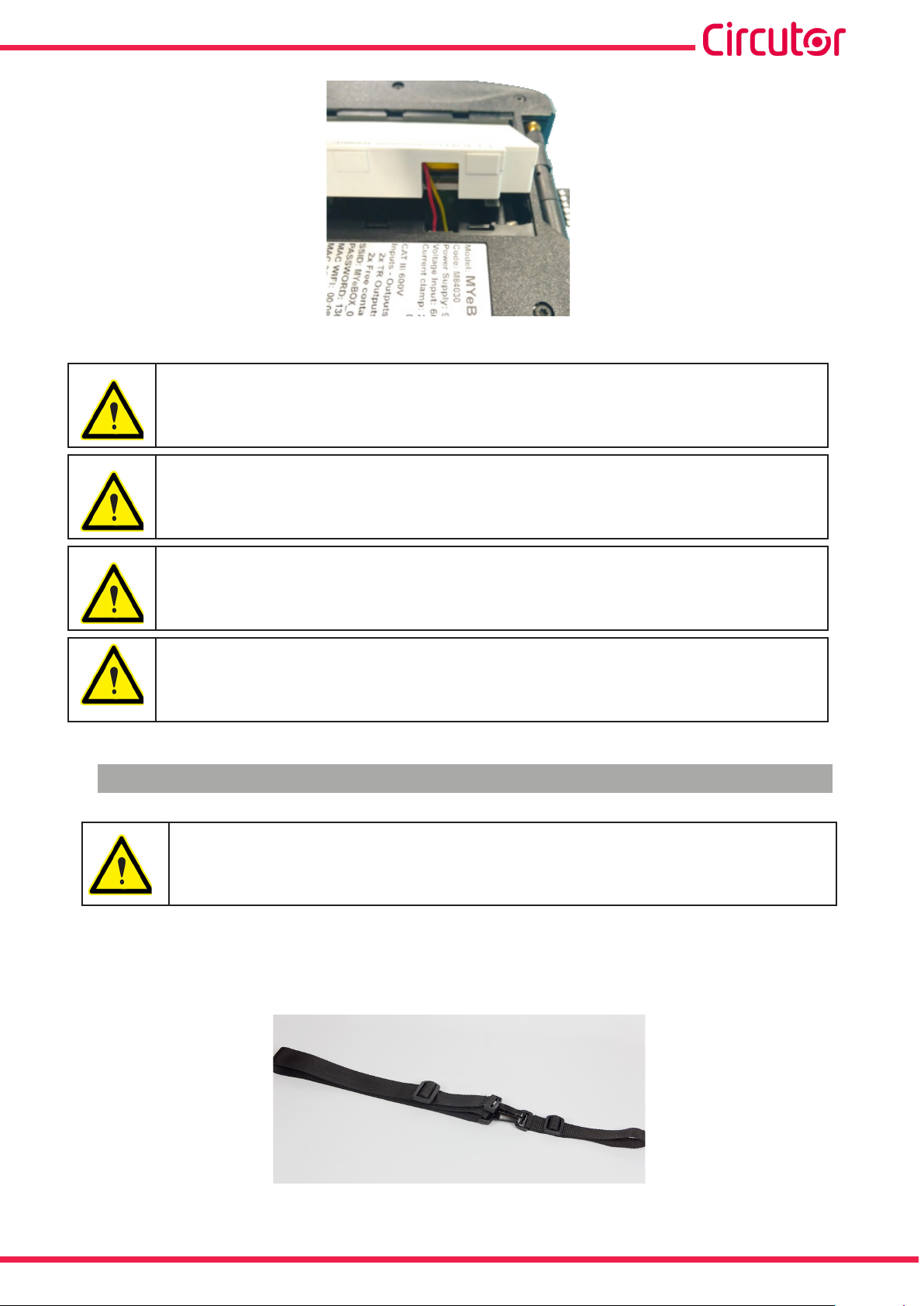
Insert the connection cable inside the battery cover, Figure 4.
Figure 4:Insert the connection cable inside the battery cover�
Insert the battery into its correct position and replace the cover. (Figure 5)
Be careful not to pinch the battery cables when inserting it.
12
Instruction Manual
Page 13
MYeBOX 150 - MYeBOX 1500
Disconnect the battery if the device is going to be idle for more than 3 months.
Figure 5: Inserting the battery�
If the device has been without power for more than 4 weeks, it is recommended
to load a few hours before use.
The battery reaches its maximum capacity after it is fully charged and discharged
a few times.
Do not charge the battery at temperatures above 40ºC or below 0ºC.
Battery charger selected is not for outdoor use.
3.3.- INSTALLATION
Terminals, opening covers or removing elements can expose parts that are hazardous to the touch while the device is powered. Do not use the device until it is
fully installed.
3�3�1�- MAGNETIC FASTENING STRAP
The MYeBOX has an optional fastening strap.
Figure 6: Fastening strap�
Instruction Manual
13
Page 14
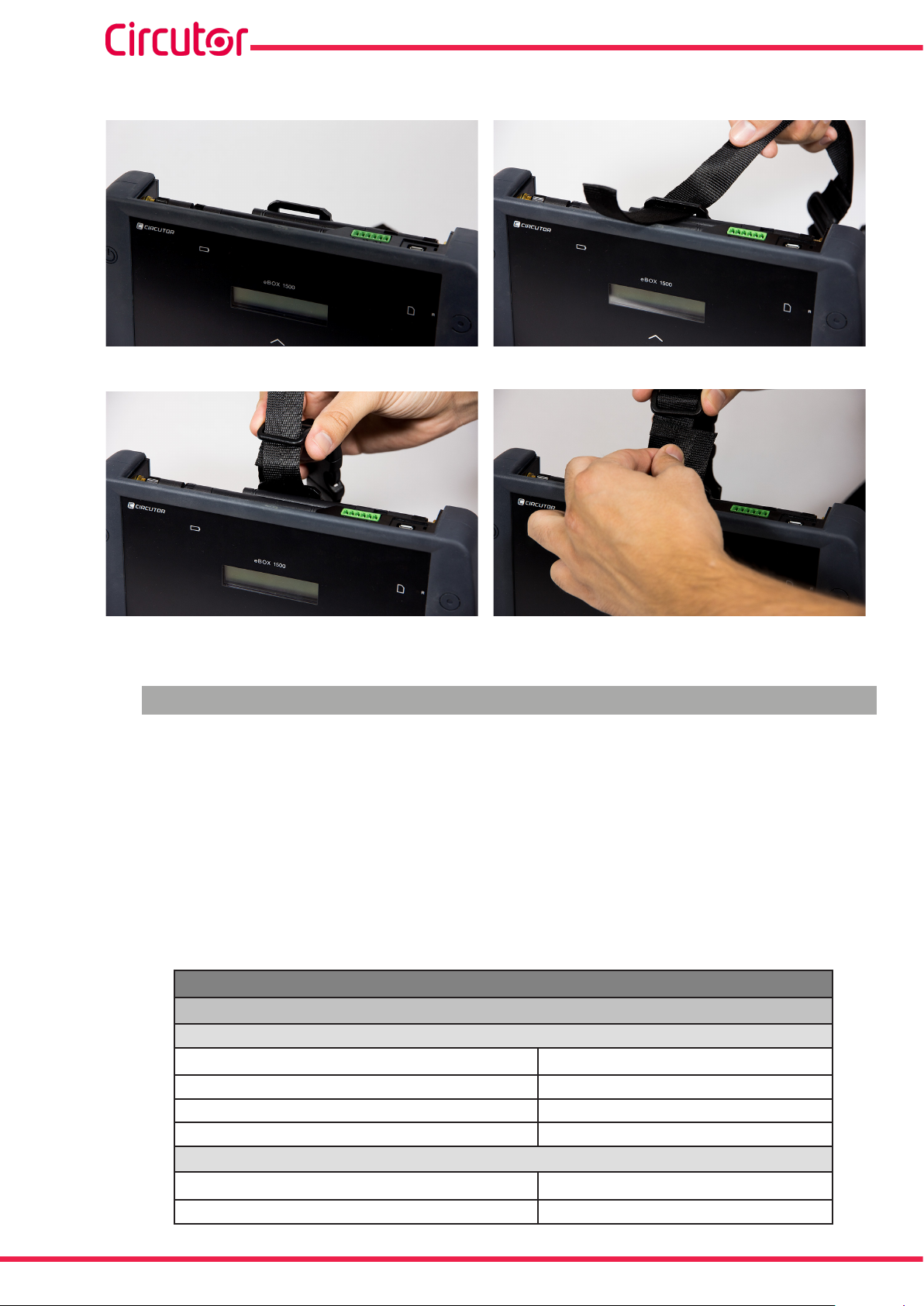
To install the strap on the device, follow these steps:
Figure 7: Installation of the fastening strap: Steps 1 and 2�
MYeBOX 150 - MYeBOX 1500
Figure 8: Installation of the fastening strap: Steps 3 and 4�
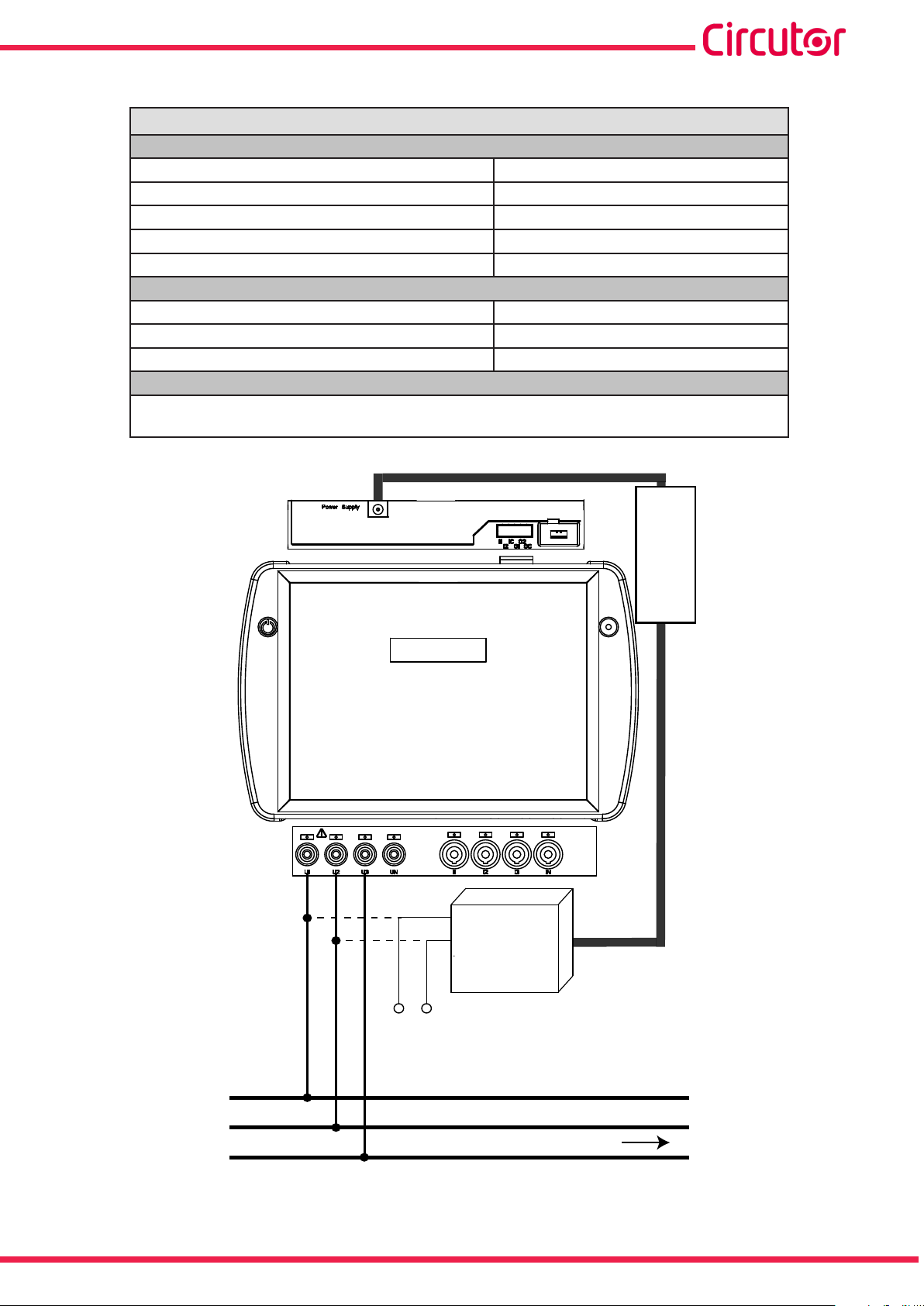
3.4.- MYeBOX 480V ~ PSU ADAPTER : POWER SUPPLY ADAPTER
Note : The MYeBOX 480V ~ power supply adapter is an accessory sold separately.
The MYeBOX 480V~ PSU ADAPTER is a highly efcient universal power supply adapter, de-
signed to power and charge the MYeBOX portable power analyser.
Designed for CAT IV 300 V, it operates at 230V ... 480V ~
The adapter comes with banana cables, which allow it to be connected to the majority of systems, and an adapter cable to connect it to the MYeBOX analyser.
Table 3:MYeBOX 480V~ PSU ADAPTER Technical features�
TECHNICAL FEATURES
Power supply
Input
Rated voltage 230 ... 480 V ~
14
Frequency 47 ... 63 Hz
Consumption 8 ... 47 VA
Installation category CAT IV 300 V
Output
Maximum output voltage 370 Vpeak
Maximum output current 1.5 A peak
Instruction Manual
Page 15
MYeBOX 150 - MYeBOX 1500
Table 3 (Continuation): MYeBOX 480V~ PSU ADAPTER Technical features�
Operating temperature 0ºC ... +40ºC
Storage temperature -20ºC ... +70ºC
Relative Humidity (non-condensing) 5 ... 95 %
Maximum altitude 2000 m
Protection degree IP30
Dimensions 78.8 x 78.8 x 53.1 mm
Weight 168 g.
Enclosure ABS (UL-94-V0)
UNE-EN 61010-1:2011, UNE-EN 61000-6-2:2006, UNE-EN 61010-6-4:2007, UL 61010-1 3rd
Edition 2012-05-11, CAN/CSA-C22.2 No. 61010-1-12 3rd Edition 2012-05
ALIMENTACIÓN AUXILIAR
Output
Environmental features
Mechanical features
Standars
POWER SUPPLY
U1 U2 U3
MY
eBOX 15xx
MYeBOX 480V~
PSU ADAPTER
POWER SUPPLY
ALIMENTACIÓN AUXILIAR
Instruction Manual
L1
L2
CARGA / LOAD
L3
Figure 9:MYeBOX 480V~ PSU ADAPTER connection�
15
Page 16
MYeBOX 150 - MYeBOX 1500
3.5.- VOLTAGE CABLES
To measure voltage, you must use 600 V CAT III double-insulated connection cables.
The Kit B_MYeBOX 150 and Kit B_MYeBOX 1500 kits come with the necessary cables:
- UL 600 V CAT III double-insulated voltage cables, or higher.
- UL 600 V CAT III crocodile clamps
Coloured markers are included with the devices to identify the measuring channels according
to each country's standard.
Table 4: Cable colours: European (IEC 60445 :2010)�
Phase Cable colour
L1 Brown
L2 Black
L3 Grey
N Light blue
I Leak Maroon
Earth Green / Yellow
3.6.- CURRENT CLAMPS
The current may be measured using current clamps or transformer clamps.
The device automatically recognises the clamps that are connected to it and shows the necessary parameters in the setup menu. (“6.1.- SETUP MENU: MEASURE SETUP”)
Using clamps is necessary IEC 61010-2-032.
Phase and neutral current measurement:
Table 5: Clamps and transformers for measuring the phase current and the neutral current�
Type Scale Measurement range Accuracy
CPG-5 - 0.05 ... 5 A 0.2% (3 % ... 120% In)
CPG-100 - 1 ... 100 A 0.2% (3 % ... 120% In)
CPRG-500 - 1 ... 500 A 0.2% (3 % ... 120% In)
CPRG-1000 - 1 ... 1000 A 0.2% (3 % ... 120% In)
CPG-200/2000
FLEX-Rxxx
Transformer ���/ 0�333V
LOW
HI
LOW
MEDIUM
HI
-
1 ... 200 A 0.2% (3 % ... 120% In)
10 ... 2000 A 0.2% (3 % ... 120% In)
100 A 1% (10 % ... 200% In)
1000 A 1% (10 % ... 200% In)
10000 A 1% (10 % ... 200% In)
1% ... 200% In
1% (1% ... 19% In)
0.5% (20% ... 120% In)
(1)
16
Instruction Manual
Page 17
MYeBOX 150 - MYeBOX 1500
Table 5 (Continuation):Clamps and transformers for measuring the phase current and the neutral current�
Type Scale Measurement range Accuracy
(1)
Transformer ���/ 0�250A
Accuracy is given by the following measurement conditions for input 2V: exclusion of errors produced by the
-
1% ... 200% In 0.5% (1% ... 200% In)
(1)
clamps and external voltage transformers, with a range in temperature of 5 ... 45 ºC and power factor 0 ... 1.
The 3 phase clamps L1, L2 and L3 must be of the same type. Otherwise, an
error event is logged in the EVA le; in this case measurements can be taken
with the device using the features of the L1 clamp.
Measurement of the leakage current, ILeak (MYeBOX 1500 model):
Table 6: Clamps and transformers for measuring the leakage current�
Type Scale Measurement range Accuracy
CFG-5 - 0.01 ... 5 A 0.2% (3 % ... 200% In)
CFG-10 - 0.02 ...10 A 0.2% (3 % ... 200% In)
Transformer WG - 1% ... 500% In 1% (10% ... 200% In)
(2)
Accuracy is given by the following measurement conditions for input 2V: exclusion of errors produced by the
clamps and external voltage transformers, with a range in temperature of 5 ... 45 ºC and power factor 0 ... 1.
(2)
Note: Transformers must be connected to the device with connectors and the corresponding
EEPROM in order for them to work.
3.7.- DEVICE TERMINALS
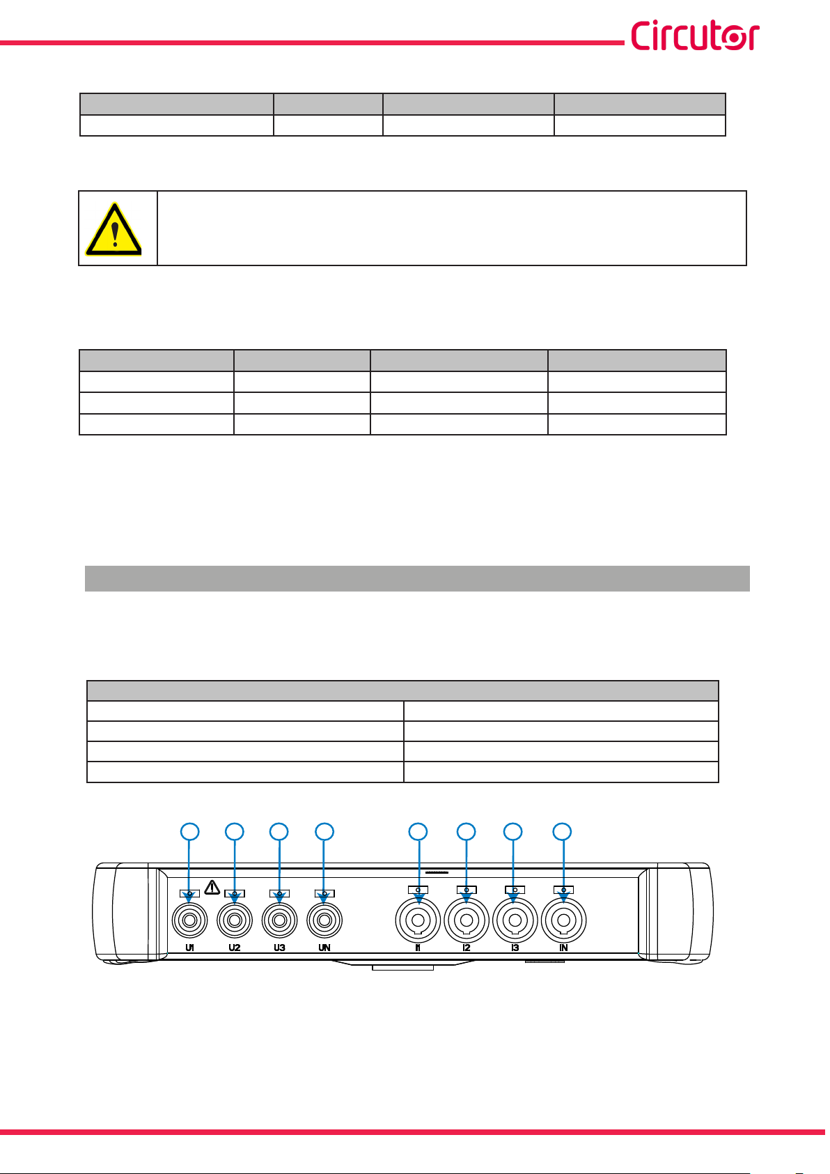
3�7�1�- MYeBOX 150
Table 7:List of terminals on the lower face of the MYeBOX 150�
Device terminals on the lower face of the MYeBOX 150
1: U1, Voltage input L1 5: I1, Current input L1
2: U2, Voltage input L2 6: I2, Current input L2
3: U3, Voltage input L3 7: I3, Current input L3
4: UN, Voltage input neutral
1 2 3 4 5 6 7 8
8: IN, Neutral current input
Instruction Manual
Figure 10:MYeBOX 150 terminals, lower face�
17
Page 18
MYeBOX 150 - MYeBOX 1500
Table 8:List of terminals on the upper face of the MYeBOX 150�
Device terminals on the upper face of the MYeBOX 150
9: Power Supply, auxiliary power supply. 10: μUSB, μUSB connector.
9
Figure 11:MYeBOX 150 terminals, upper face�
10
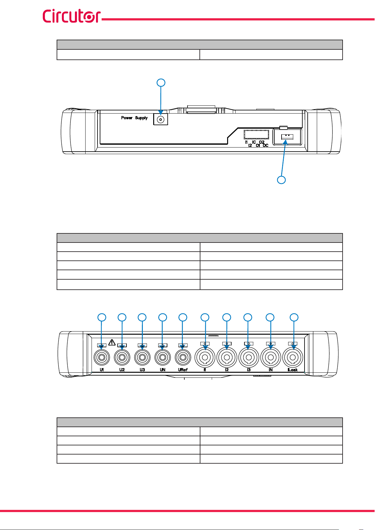
3�7�2�- MYeBOX 1500
Table 9:List of terminals on the lower face of the MYeBOX 1500�
Device terminals on the lower face of the MYeBOX 1500
1: U1, Voltage input L1 6: I1, Current input L1
2: U2, Voltage input L2 7: I2, Current input L2
3: U3, Voltage input L3 8: I3, Current input L3
4: UN, Voltage input neutral
5: URef, Reference voltage input.
1 2 3 4 5 6 7 8 9 10
Figure 12:MYeBOX 1500 terminals, lower face�
9: IN, Neutral current input
10: ILeak, Leakage current input
18
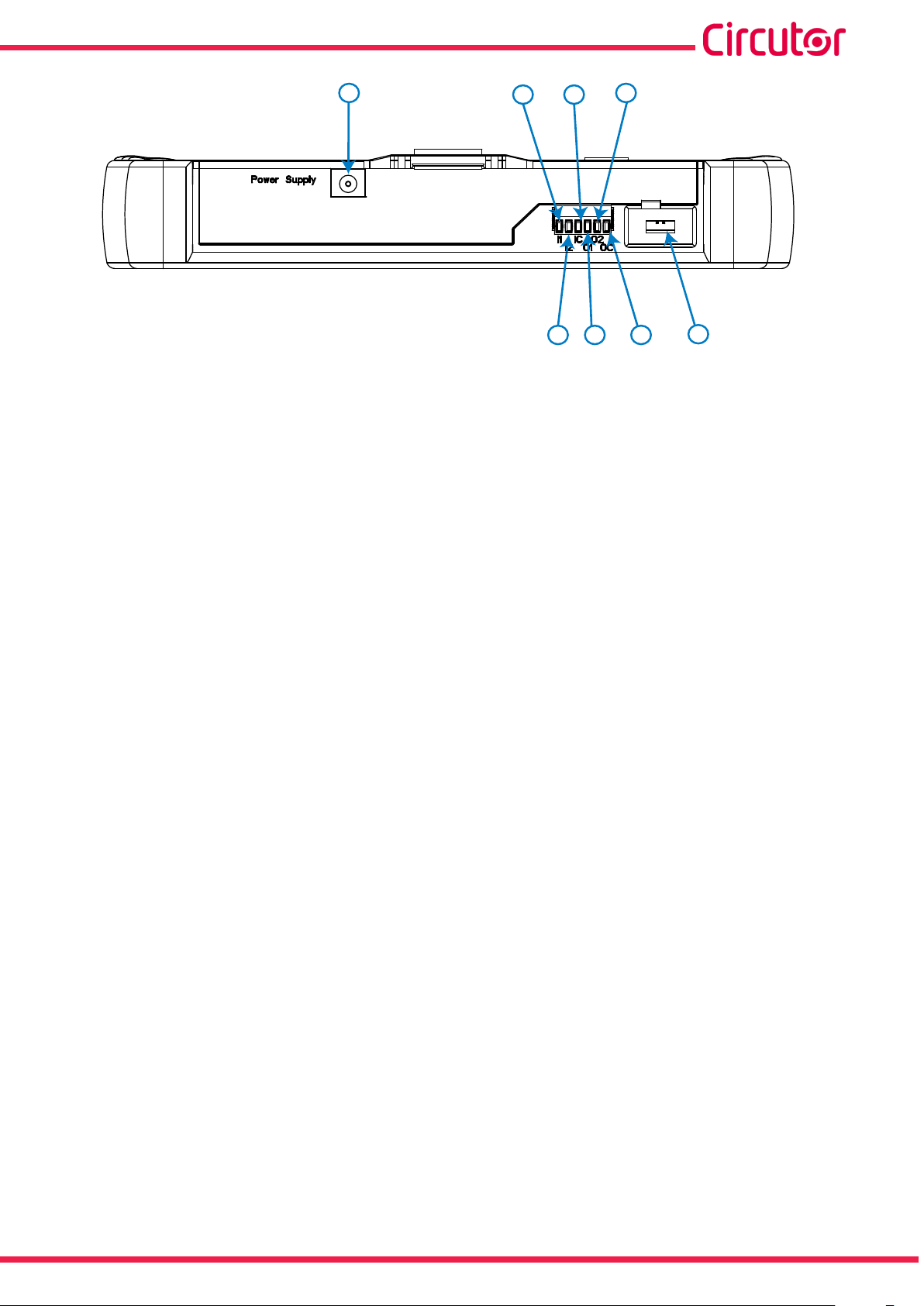
Table 10:List of terminals on the upper face of the MYeBOX 1500�
Device terminals on the upper face of the MYeBOX 1500
11: Power Supply, auxiliary power supply. 15: O1, Transistor output 1
12: I1, Digital input 1 16: O2, Transistor output 2
13: I2, Digital input 2 17: OC, GND for transistor outputs
14: IC, GND for digital inputs 18: μUSB, μUSB connector.
Instruction Manual
Page 19
MYeBOX 150 - MYeBOX 1500
11
Figure 13:MYeBOX 1500 terminals, upper face�
12
131415
16
17
18
Instruction Manual
19
Page 20
MYeBOX 150 - MYeBOX 1500
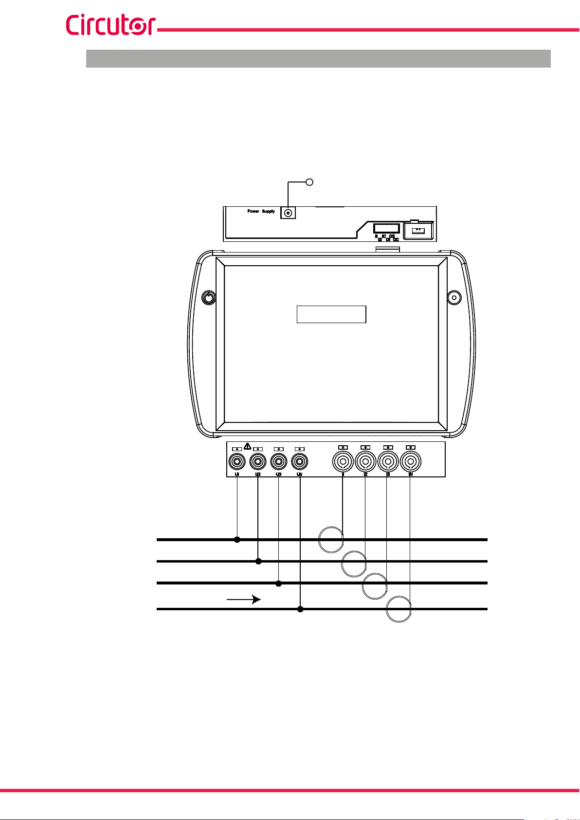
3.8.- CONNECTION DIAGRAMS
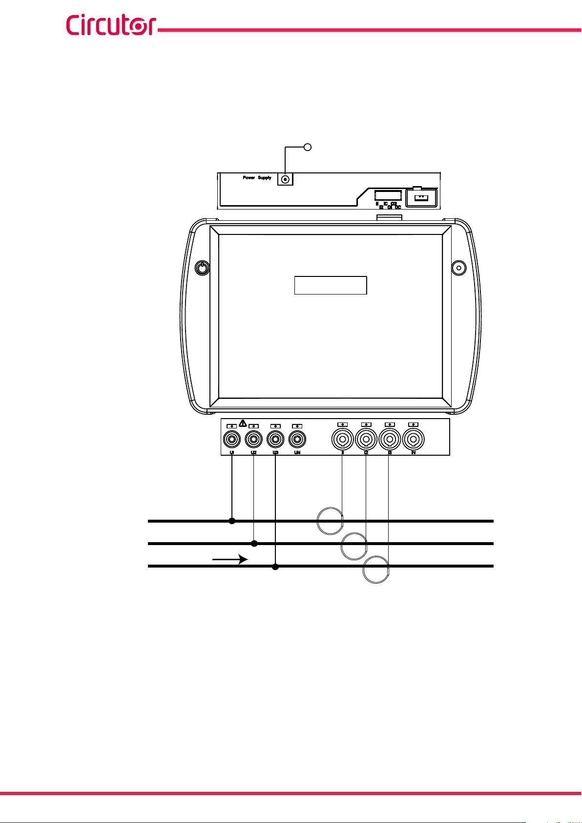
3�8�1�- THREE-PHASE NETWORK MEASURING WITH A 4-WIRE CONNECTION, MYeBOX 150�
Type of installation (Select circuit)
(3)
: 3 Phases + Neutral.
ALIMENTACIÓN AUXILIAR
POWER SUPPLY
MY
eBOX 150
U1
U2 U3 UN I1 I2 I3 IN
L1
L2
L3
CARGA / LOAD
N
Figure 14: Three-phase measuring with a 4-wire connection (MYeBOX 150)�
Note: See section “3.8.10.- DETAIL OF THE CURRENT MEASUREMENT CONNECTION.”
(3)
See “5.2.- DISPLAY MENU: DEVICE PROFILE”
20
Instruction Manual
Page 21
MYeBOX 150 - MYeBOX 1500
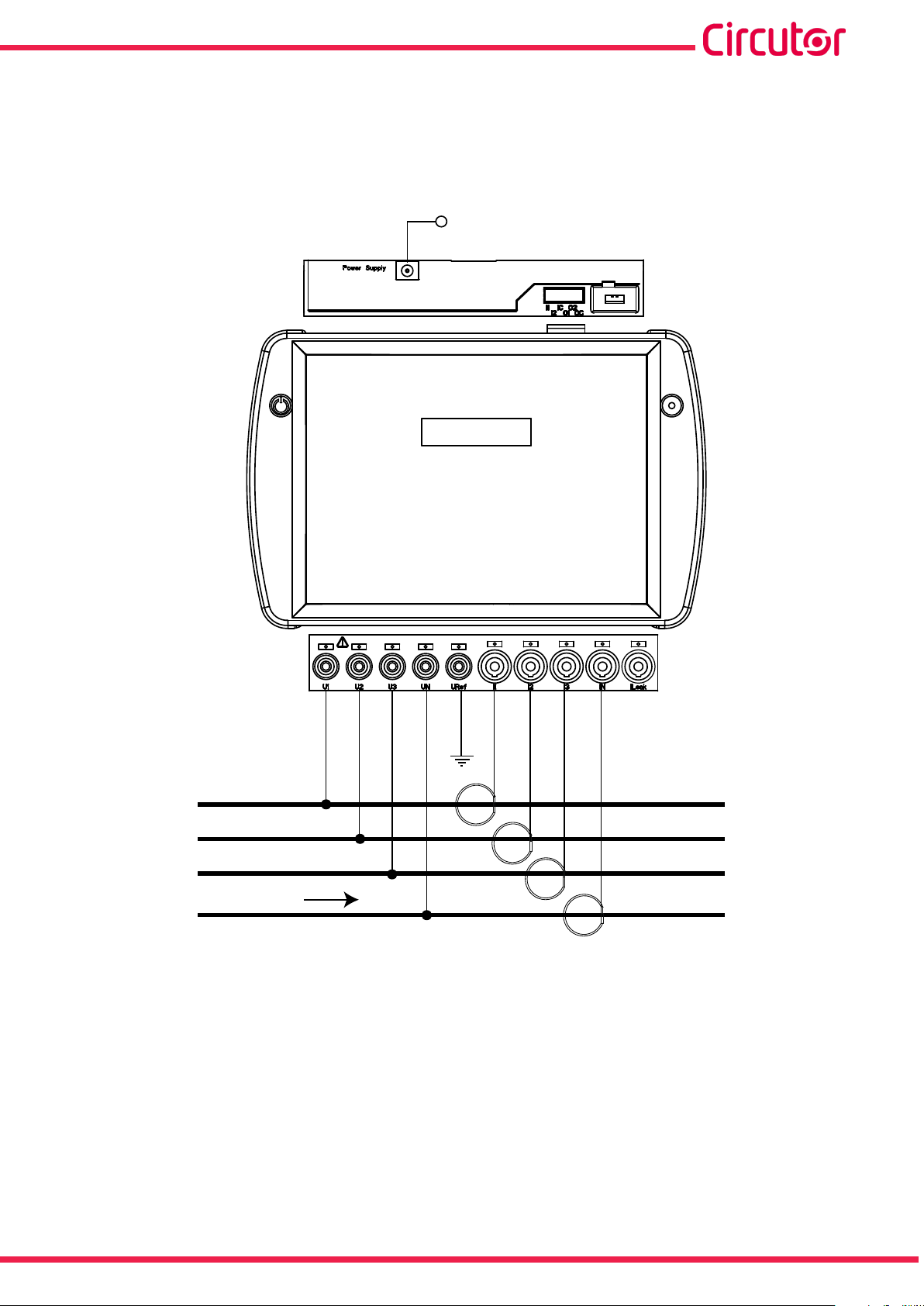
3�8�2�- THREE-PHASE NETWORK MEASURING WITH A 4-WIRE CONNECTION, MYeBOX 1500�
Type of installation (Select circuit)
(4)
: 3 Phases + Neutral.
ALIMENTACIÓN AUXILIAR
POWER SUPPLY
MY
eBOX 1500
U1
U2 U3 UN
URef
I1 I2 I3 IN
L1
L2
L3
CARGA / LOAD
N
Figure 15: Three-phase measuring with a 4-wire connection (MYeBOX 1500)�
Note: See section “3.8.10.- DETAIL OF THE CURRENT MEASUREMENT CONNECTION.”
(4)
See “5.2.- DISPLAY MENU: DEVICE PROFILE”
Instruction Manual
21
Page 22
MYeBOX 150 - MYeBOX 1500
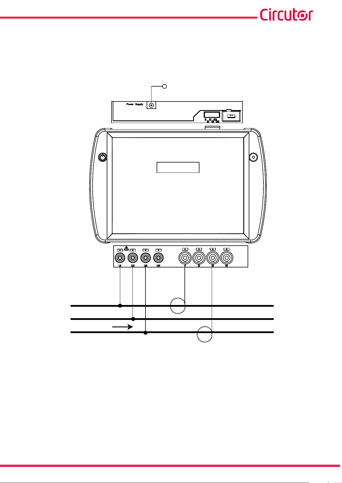
3�8�3�- THREE-PHASE NETWORK MEASURING WITH A 3-WIRE CONNECTION, MYeBOX
150 AND MYeBOX1500�
Type of installation (Select circuit)
(5)
: 3 Phases.
MY
eBOX 150
ALIMENTACIÓN AUXILIAR
POWER SUPPLY
U1
U2 U3 I1 I2 I3
L1
L2
CARGA / LOAD
L3
Figure 16: Three-phase measuring with a 3-wire connection (MYeBOX 150, MYeBOX 1500)�
Note: See section “3.8.10.- DETAIL OF THE CURRENT MEASUREMENT CONNECTION.”
(5)
See “5.2.- DISPLAY MENU: DEVICE PROFILE”
22
Instruction Manual
Page 23
MYeBOX 150 - MYeBOX 1500
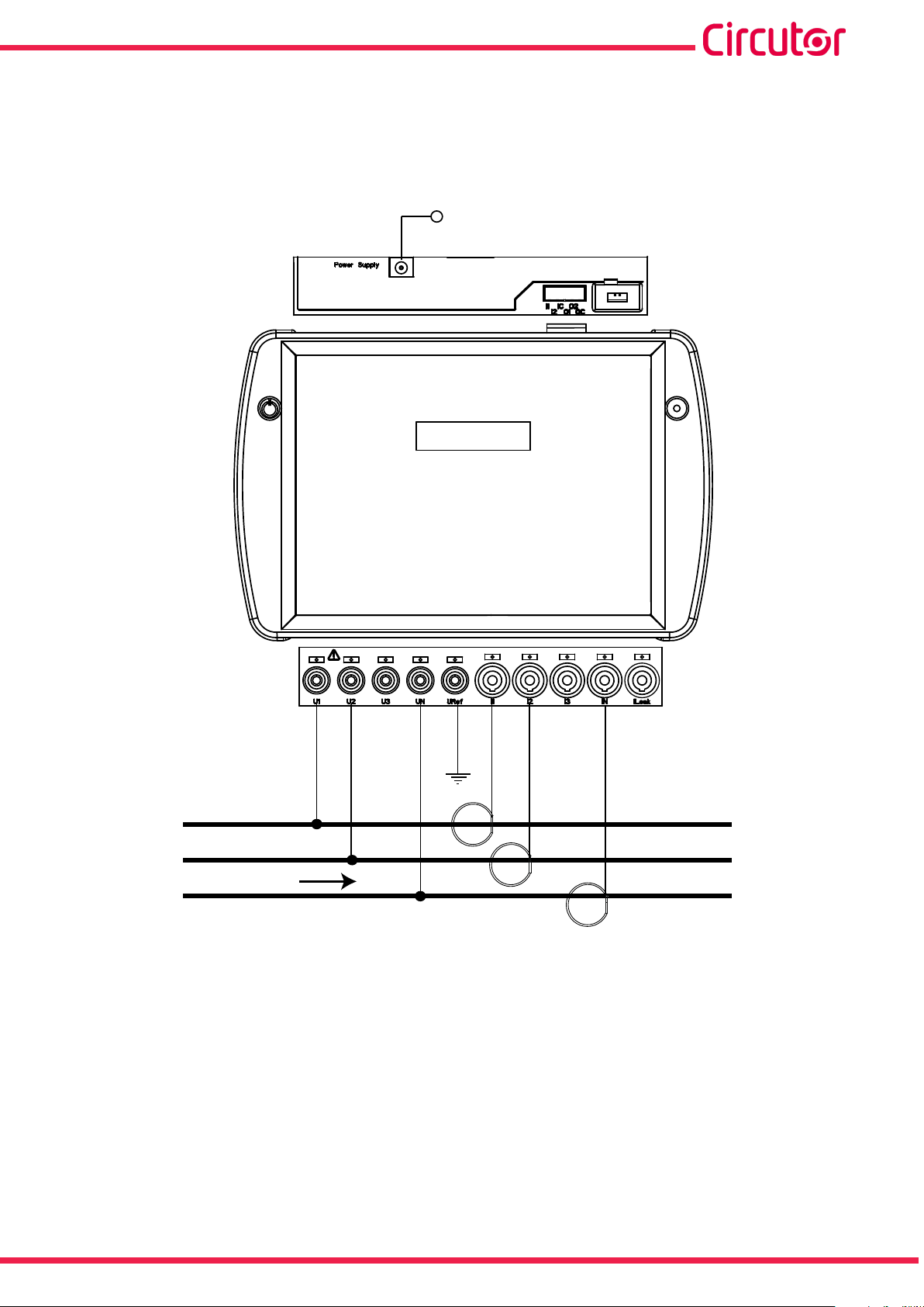
3�8�4�- THREE-PHASE NETWORK MEASURING WITH A 3-WIRE CONNECTION AND ARON
CONNECTION, MYeBOX 150 AND MYeBOX 1500�
Type of installation (Select circuit)
(6)
: Aron.
ALIMENTACIÓN AUXILIAR
POWER SUPPLY
MY
eBOX 150
U1
U2 U3 I1 I3
L1
L2
CARGA / LOAD
L3
Figure 17: Three-phase measuring with a 3-wire connection and an ARON connection (MYeBOX 150, MYeBOX 1500)�
Note: See section “3.8.10.- DETAIL OF THE CURRENT MEASUREMENT CONNECTION.”
(6)
See “5.2.- DISPLAY MENU: DEVICE PROFILE”
Instruction Manual
23
Page 24

MYeBOX 150 - MYeBOX 1500
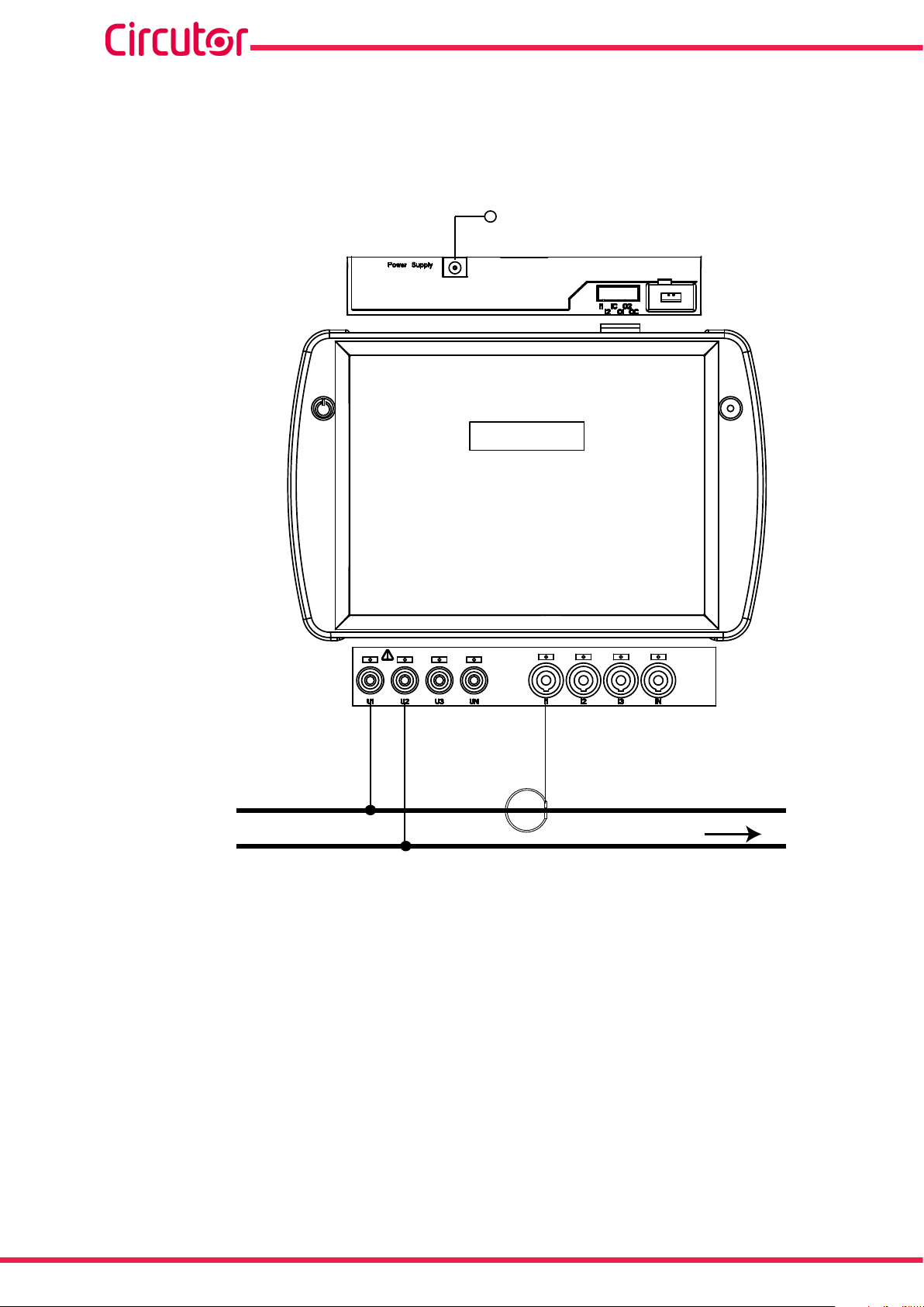
3�8�5�- TWO-PHASE NETWORK MEASURING WITH A 3-WIRE CONNECTION, MYeBOX 150�
Type of installation (Select circuit)
(7)
: 2 Phases + Neutral.
ALIMENTACIÓN AUXILIAR
POWER SUPPLY
MY
eBOX 150
U1
U2 UN I1 I2 IN
L1
L2
CARGA / LOAD
N
Figure 18: Two-phase measuring with a 3-wire connection (MYeBOX 150)�
Note: See section “3.8.10.- DETAIL OF THE CURRENT MEASUREMENT CONNECTION.”
(7)
See “5.2.- DISPLAY MENU: DEVICE PROFILE”
24
Instruction Manual
Page 25
MYeBOX 150 - MYeBOX 1500
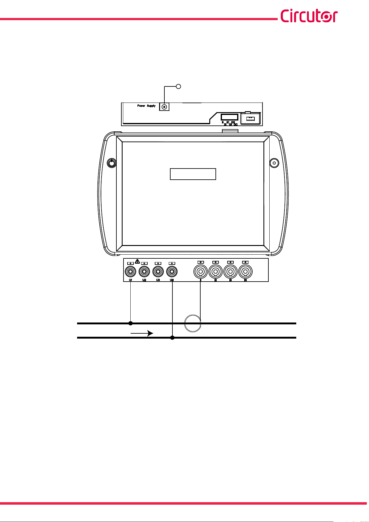
3�8�6�- TWO-PHASE NETWORK MEASURING WITH A 3-WIRE CONNECTION, MYeBOX 1500�
Type of installation (Select circuit)
(8)
: 2 Phases + Neutral.
ALIMENTACIÓN AUXILIAR
POWER SUPPLY
MY
eBOX 1500
U1NU2
UN
URef
I1 I2 IN
CARGA / LOAD
Figure 19: Two-phase measuring with a 3-wire connection (MYeBOX 1500)�
Note: See section “3.8.10.- DETAIL OF THE CURRENT MEASUREMENT CONNECTION.”
(8)
See “5.2.- DISPLAY MENU: DEVICE PROFILE”
Instruction Manual
25
Page 26
MYeBOX 150 - MYeBOX 1500
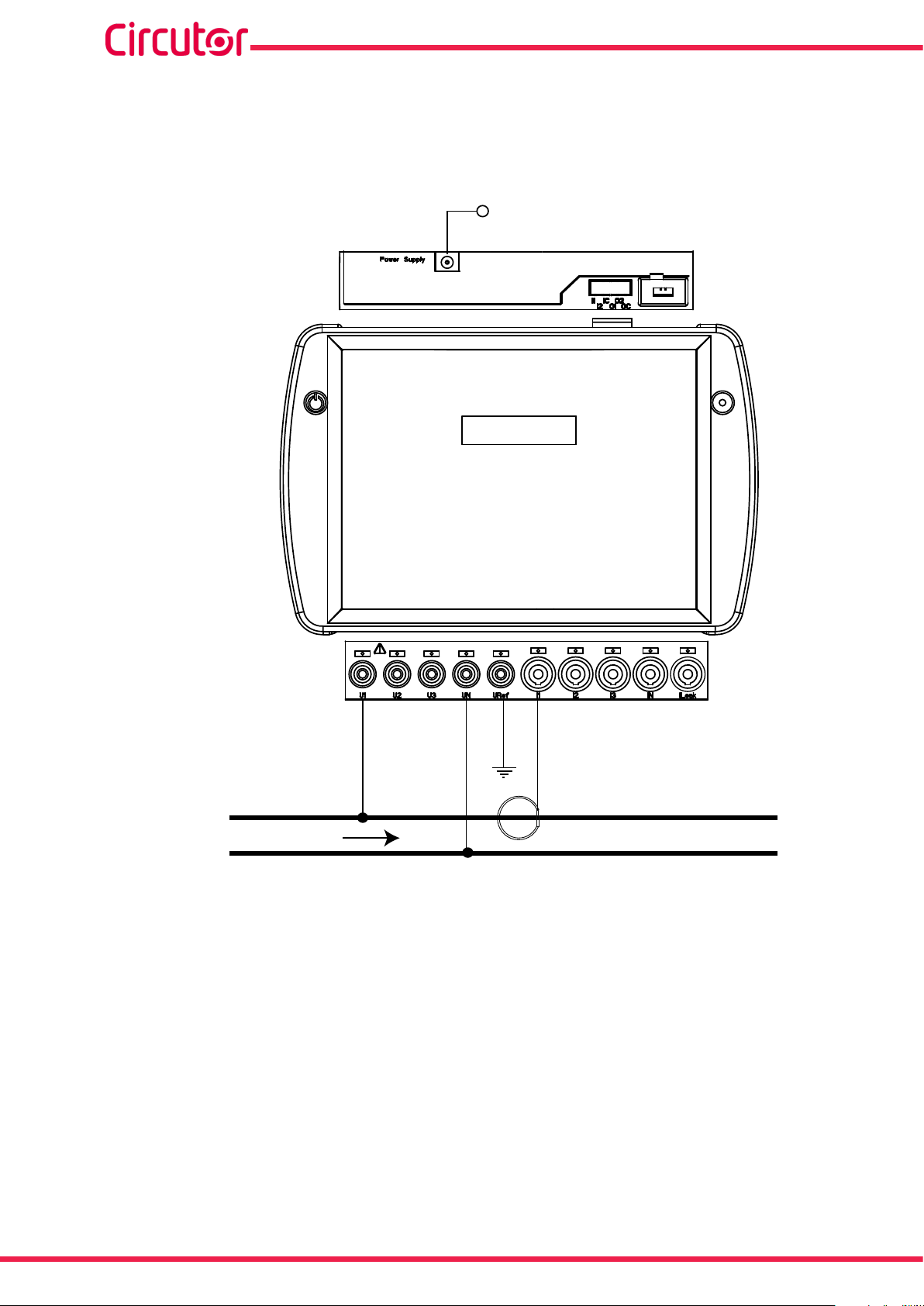
3�8�7� - SINGLE-PHASE NETWORK MEASUREMENT, PHASE TO PHASE, WITH A 2-WIRE
CONNECTION, MYeBOX 150 AND MYeBOX 1500�
Type of installation (Select circuit)
(9)
: 2 Phases.
MY
eBOX 150
ALIMENTACIÓN AUXILIAR
POWER SUPPLY
U1
U2 I1
L1
L2
Figure 20: Single-phase measurement, phase to neutral, with a 2-wire connection (MYeBOX 150, MYeBOX 1500)�
CARGA / LOAD
Note: See section “3.8.10.- DETAIL OF THE CURRENT MEASUREMENT CONNECTION.”
(9)
See “5.2.- DISPLAY MENU: DEVICE PROFILE”
26
Instruction Manual
Page 27
MYeBOX 150 - MYeBOX 1500
3�8�8�- SINGLE-PHASE NETWORK MEASUREMENT, PHASE TO NEUTRAL, WITH A
2-WIRE CONNECTION, MYeBOX 150�
Type of installation (Select circuit)
(10)
: 1 Phase + Neutral.
ALIMENTACIÓN AUXILIAR
POWER SUPPLY
MY
eBOX 150
U1
UN
I1
L1
CARGA / LOAD
N
Figure 21: Single-phase measurement, phase to neutral, with a 2-wire connection (MYeBOX 150)�
Note: See section “3.8.10.- DETAIL OF THE CURRENT MEASUREMENT CONNECTION.”
(10)
See “5.2.- DISPLAY MENU: DEVICE PROFILE”
Instruction Manual
27
Page 28
MYeBOX 150 - MYeBOX 1500
3�8�9�- SINGLE-PHASE NETWORK MEASUREMENT, PHASE TO NEUTRAL, WITH A
2-WIRE CONNECTION, MYeBOX 1500�
Type of installation (Select circuit)
(11)
: 1 Phase + Neutral.
ALIMENTACIÓN AUXILIAR
POWER SUPPLY
MY
eBOX 1500
U1
UN
URef
I1
L1
CARGA / LOAD
N
Figure 22: Single-phase measurement, phase to neutral, with a 2-wire connection (MYeBOX 1500)�
Note: See section “3.8.10.- DETAIL OF THE CURRENT MEASUREMENT CONNECTION.”
(11)
See “5.2.- DISPLAY MENU: DEVICE PROFILE”
28
Instruction Manual
Page 29
MYeBOX 150 - MYeBOX 1500
POWER SUPPLY
ALIMENTACIÓN AUXILIAR
eBOX 1500
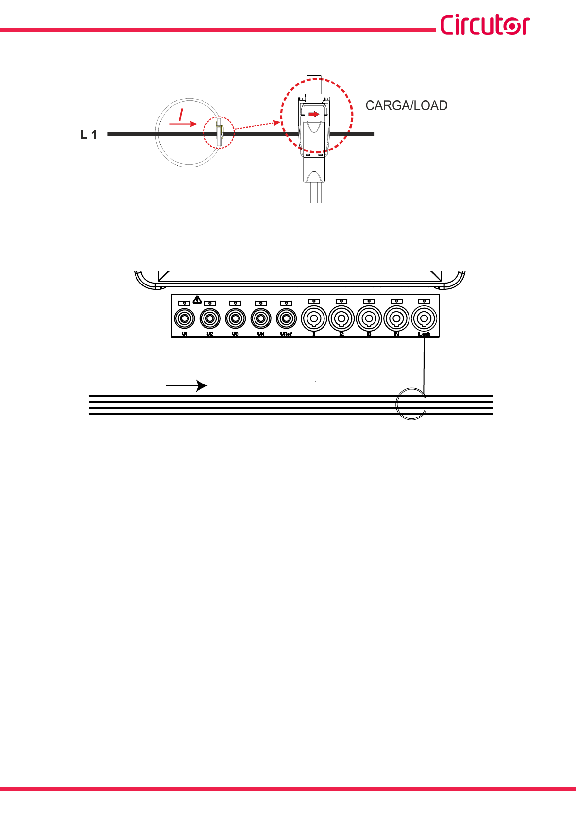
3�8�10�- DETAIL OF THE CURRENT MEASUREMENT CONNECTION�
Figure 23: Detail of the current measurement connection�
3�8�11�- LEAKAGE CURRENT CONNECTION, ILeak� (MYeBOX 1500 MODEL)
L1
L2
L3
N
CARGA /LOAD
Figure 24: Connection of the leakage current, ILeak (MYeBOX 1500)�
ILeak
Instruction Manual
29
Page 30

MYeBOX 150 - MYeBOX 1500
3.9.- REGISTERING AND UPDATING THE DEVICE
Before using the device for the rst time, it is necessary to:
1�- Register the MYeBOX on the web page www�myebox�es
2�- Register the device on a network with Internet connection.
3�- Download the latest version of the mobile application MYeBOX, which can be found in the
App Store and on Google Play.
4�- Connect to the device from the mobile application.
5�- Once the device is connected to the application, it is necessary to check whether there is
a later version of the device’s rmware. If there is a new rmware version, the application will
display the message in Figure 25
Figure 25: MyEBOX application screen indicating a new version�
To download and install the new version, go to Setup, select the option Firmware and press
START. The device will download the package and start the update automatically.
30
Figure 26: MYeBOX rmware update screen.
Instruction Manual
Page 31

MYeBOX 150 - MYeBOX 1500
0º
90º
180º
-90º
PF Cos φ -
kW kVA
kvarC
kvar -
PF +
Cos φ +
kW kVA
kvarL
kvar +
kW +
kVA
kvarC
kvar -
kW +
kVA
kvarL
kvar +
PF +
Cos φ +
PF Cos φ -
kW III = kW L1 + kW L2 + kW L3
kVA III = kVA L1 + kVA L2 + kVA L3
kvarL III = kvarL L1 + kvarL L2 + kvarL L3
kvarC III = kvarC L1 + kvarC L2 + kvarC L3
PF III = kW III / kVA III
Cos φ III = ( Cos φ L1 + Cos φ L2 + Cos φ L3 ) / 3
Generation
Power
Consumption
Power
4�- OPERATION
4.1.- OPERATING PRINCIPLE
The MYeBOX is a four-quadrant portable power analyzer (consumption and generation).
Figure 27: Four quadrants of the MYeBOX�
In addition to the basic functions of any analyzer, the MYeBOX:
Allows conguration and display of data:
- Remotely, via a tablet or smartphone, using a mobile application.
- Locally, via the display and the device's capacitive keypad.
It has a database for logging all the device's parameters and events.
It has MicroSD memory to store the STD, EVA and EVQ les of the database logs.
Comes standard with built-in Wi-Fi communications.
The MYeBOX1500 models comes standard with built-in 3G communications.
It has a lithium battery that guarantees the device's battery life, in order to log voltage drops
in the installation and send the corresponding alarms.
Instruction Manual
31
Page 32

MYeBOX 150 - MYeBOX 1500
4.2.- MEASUREMENT PARAMETERS
The device measures and logs different types of parameters:
Electrical parameters,
Quality parameters (EVQ) such as overvoltages, gaps and outages, in accordance with
EN50160.
Wave shapes of the different channels.
All the measurement parameters can be viewed on the MYeBOX mobile application, as shown
in Table 11.
Table 11: MYeBOX measurement parameters�
Parameter Units
(12)
(12)
Vph-N
Vph-ph
A
Phase-neutral voltage
Phase-phase voltage
Current
(12)
Leakage current A
Frequency
Active power
Apparent power
Inductive reactive power
Capacitive reactive power
Power factor
(12)
(12)
(12)
(12)
(12)
(12)
kvarC
Hz
kW
kVA
kvarL
PF
Crest factor CF
K-factor -
Cos φ
(12)
φ
Voltage THD % % THD V
Current THD % % THD A
Harmonic Breakdown - Voltage(up to the 50th order harmonic)
Harmonic Breakdown - Current (up to the 50th order harmonic)
Instantaneous icker
PST Flicker
harm V
harm A
Pinst
Pst
Active energy kWh
Inductive Reactive Energy kvarLh
Capacitive Reactive Energy kvarCh
Apparent energy kVAh
Voltage unbalance
Voltage asymmetry
(12)
(12)
-
-
Current unbalance -
Current asymmetry -
Maximum Current Demand A
Maximum Demand for Active Power kW
Maximum Demand for Apparent Power kVA
Wave shapes -
Phasor representation -
Phases
L1-L2-L3
(L1)
Total
N
III
32
Instruction Manual
Page 33

MYeBOX 150 - MYeBOX 1500
Table 11 (Continued): MYeBOX measurement parameters�
Parameter Units Tariff: T1-T2
No. of hours of active tariff
(12)
Cost
CO2 Emissions
(12)
Parameters shown on the device's display.
(12)
(12)
hours
COST
kgCO
2
4�2�1�- QUALITY PARAMETERS
Power quality control requires dening the TRMS of the voltage level, subsequently used by
the analyzer to record events. According to Standard EN-61000-4-30, the RMS value must be
calculated for all the AC magnitudes or each cycle and refresh every ½ cycle. If the RMS value
exceeds certain programmed thresholds, this is understood as an event�
The device detects quality parameters such as overvoltages, gaps, voltage outages and transients. Figure 28 shows an example of these events.
Figure 28:Example of quality events�
Overvoltage
An overvoltage event is shown in the time interval t0 in Figure 28 . The duration of the event
is the time that the signal stays above the congured threshold value (“6.3.1.- OVERVOLTAGE,
SWELL”). In this example it is 110% of the rated voltage plus the time the signal takes to fall
below the congured value, including a hysteresis of 2%.
Voltage gap
In the time intervals t1 and t3 of Figure 28 there are two voltage gaps. The duration of the event
is the time that the signal stays below the congured threshold value (“6.3.2.- GAP, SAG”). In this
example it is 90% of the rated voltage.
Voltage outage
An outage or disruption event is shown in the time interval t2 in Figure 28 . The duration of the
event is the time that the signal stays below the congured threshold value (“6.3.3.- OUTAGE,
DISRUPTION”). In this example it is 10% of the rated voltage plus the time the signal takes to
rise above the congured value, including a hysteresis of 2%.
Instruction Manual
33
Page 34

MYeBOX 150 - MYeBOX 1500
Transients
Transients are detected by checking that the difference between one sample and the next does
not exceed the maximum nominal slope value multiplied by the distortion level coefcient selected by the user (“6.3.4.- TRANSIENTS, DISTURB”).
In this case 128 samples are checked per cycle.
The maximum nominal slope value is the maximum tangent value calculated using a nominal
value selected by the user. By denition, in a sine wave this maximum slope is given by the zero
crossing, therefore the maximum slope is calculated as the value of the sine wave between
sample point 0 (zero crossing) and point 1 (rst sample).
Transients are checked and saved phase by phase. The 3 voltage phases are checked separately and when a transient is detected it saves the 15 wave shape cycles of the variable that
caused it.
Example:
Figure 29 shows the disturbances detected when conguring a distortion coefcient of 5�0
34
Figure 29: Transients detected with a distortion coefcient of 5.0.
Figure 30 shows the disturbances detected when conguring a distortion coefcient of 90�0
Instruction Manual
Page 35

MYeBOX 150 - MYeBOX 1500
Figure 30:Transients detected with a distortion coefcient of 90.0.
4.3.- KEYPAD FUNCTIONS
The MYeBOX has 5 capacitive keys and 2 buttons:
Table 12: Button functions�
Button Press
Device on/off button.
Data logging start/end button.
When the device's off button is pressed, the screen shown in Figure 31 appears to conrm the
shut-down.
POWER OFF
YES
Figure 31:Device shut-down screen (1)�
Use the and keys to select whether or not to turn off the device. And press the key
to conrm the option.
While the device is shutting down, the screen shown in Figure 32 (2) appears, and if the device
is connected to a power supply it shows the battery charge status, as shown in Figure 32 (3)�
Instruction Manual
TURNING OFF...
Figure 32:Device shut-down screens (2 and 3)�
CHARGING BATTERY
97%
35
Page 36
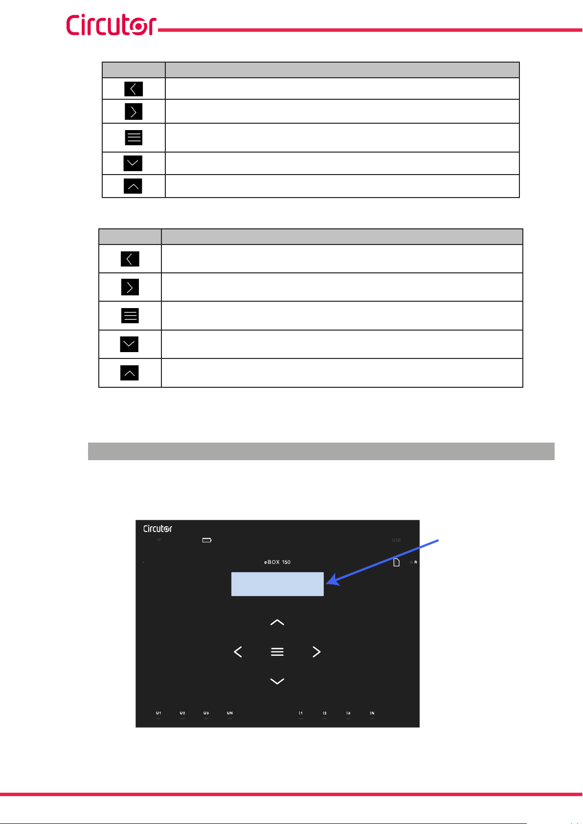
Table 13: Key functions: Display menus�
Key Press
Go to the previous display screen.
Go to the next display screen.
Access the display menu.
Access the setup menu from the Setup menu
Go to the next display menu.
Go to the previous display menu.
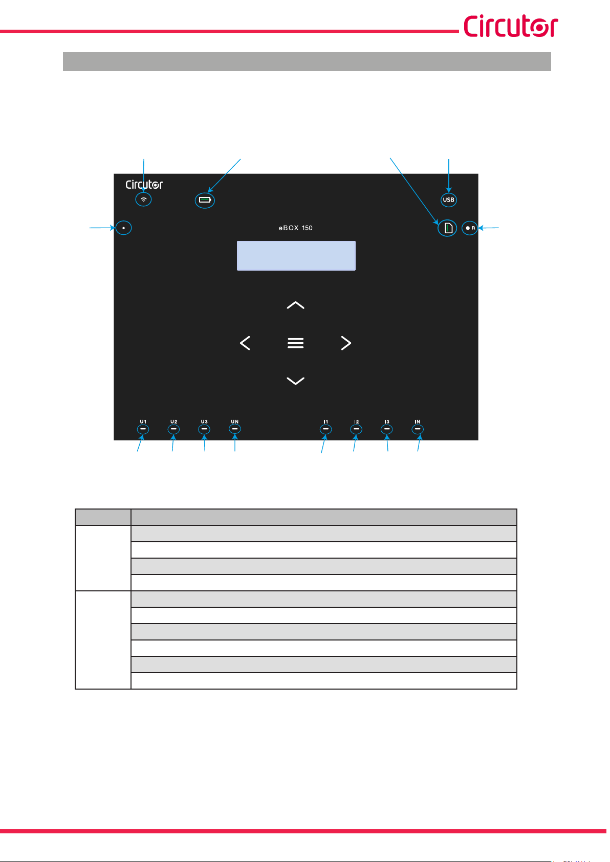
Table 14: Key functions: Setup menus�
Key Press
Go to the previous conguration screen.
Move the cursor one position to the left in edit mode.
Go to the next display screen.
Move the cursor one position to the right in edit mode.
Enter edit mode.
Conrm the selected option.
Go to the next menu option.
Decrease the value of the eld in the programming menu.
Go to the previous menu option.
Increase the value of the eld in the programming menu.
MYeBOX 150 - MYeBOX 1500
If the device is not active for 5 minutes, the backlight will turn on when you press any key or
button.
4.4.- DISPLAY
The device has a 2-line display with 20 digits on each line, for viewing all the parameters indicated in Table 11 and for conguring the device.
Display
MY
DATE TIME
25/06/2015 15:07:50
36
Figure 33: MYeBOX display
Instruction Manual
Page 37
MYeBOX 150 - MYeBOX 1500
4.5.- LED INDICATORS
4�5�1�- MYeBOX 150�
The MYeBOX 150 model has 14 indicator LEDs, as shown in Figure 34 and Table 15.
ON
Wi USB
Battery
DATE TIME
MY
Memory
25/06/2015 15:07:50
REC
U1 U2 U3 UN I1 I2 I3 IN
Figure 34:MYeBOX 150 indicator LEDs�
Table 15: LED description, MYeBOX 150�
LED Description
Power off
ON
Device off.
Blinking light (1 s)
Device on.
Power off
Wi-Fi connection disabled.
Power on
Wi-Fi
Wi-Fi connection enabled.
Blinking light (1 s)
Wi-Fi trafc.
Instruction Manual
37
Page 38
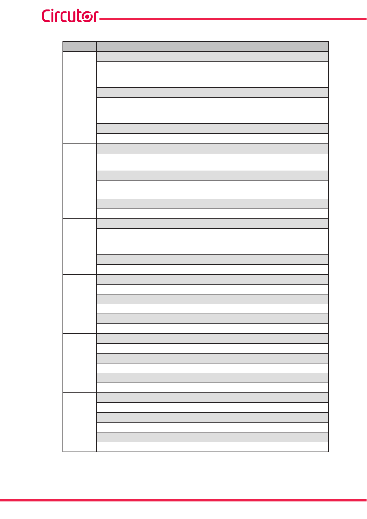
Table 15 (Continued): LED description, MYeBOX 150�
LED Description
Power on
Green: Battery charge between 70 ... 100 %.
Yellow: Battery charge between 30 ... 70 %.
Red: Battery charge between 5 ... 30 %.
Blinking light (1 s)
Battery
Green: Battery not charging, charge between 70 ... 100 %.
Yellow: Battery not charging, charge between 30 ... 70 %.
Red: Battery not charging, charge between 5 ... 30 %.
Blinking light (0�5 s)
Red: Battery not charging, charge < 5%.
Power off
No access to the MicroSD memory; the USB cable does not have to be connected.
Power on
USB
Access to the MicroSD memory is allowed; the USB cable can be connected
to access the memory.
Blinking light (1 s)
Data trafc.
Power on
Green: Space available in the memory: 55 ... 100 %.
Yellow: Space available in the memory: 25 ... 55 %.
Memory
Red: Space available in the memory: 10 ... 25 %.
Blinking light (0�5 s)
Red: Space available in the memory: < 10%.
Power off
Data not being logged.
Power on
REC
Device logging data.
Blinking light (1 s)
Log error or MicroSD memory access error.
Power off
U1
U2
U3
UN
No voltage at the corresponding input. (U1: L1, U2: L2, U3: L3, UN: LN)
Power on
Voltage at the corresponding input. (U1: L1, U2: L2, U3: L3, UN: LN)
Blinking lights U1, U2 and U3 (1 s)
L1-L2-L3 phase sequence error
Power off
I1
I2
I3
IN
Clamp not connected (I1: L1, I2: L2, I3: L3, IN: LN)
Power on
Clamp connected (I1: L1, I2: L2, I3: L3, IN: LN)
Blinking light (1 s)
Negative power or cos < ± 0.6
MYeBOX 150 - MYeBOX 1500
38
Instruction Manual
Page 39

MYeBOX 150 - MYeBOX 1500
Table 15 (Continued): LED description, MYeBOX 150�
LED Description
Power off
Clamp not connected (LN)
IN
Power on
Clamp connected (LN)
4�5�2�- MYeBOX 1500�
The MYeBOX 1500 model has 21 indicator LEDs, as shown in Figure 35 and Table 16.
ON
Wi
Battery
MY
DATE TIME
25/06/2015 15:07:50
USBIN1 IN2 OUT1 OUT23G
REC
Memory
U1 U2 U3 UN I1 I2 I3 INURef ILeak
Figure 35:MYeBOX 1500 indicator LEDs�
Table 16: LED description, MYeBOX 1500�
LED Description
Power off
ON
Device off.
Blinking light (1 s)
Device on.
Power off
Wi-Fi connection disabled.
Power on
Wi-Fi
Wi-Fi connection enabled.
Blinking light (1 s)
Wi-Fi trafc.
Instruction Manual
39
Page 40

Table 16 (Continued): LED description, MYeBOX 1500�
LED Description
Power off
3G connection disabled.
Power on
3G
3G connection enabled.
Blinking light (1 s)
3G trafc.
Power on
Green: Battery charge between 70 ... 100 %.
Yellow: Battery charge between 30 ... 70 %.
Red: Battery charge between 5 ... 30 %.
Blinking light (1 s)
Battery
Green: Battery not charging, charge between 70 ... 100 %.
Yellow: Battery not charging, charge between 30 ... 70 %.
Red: Battery not charging, charge between 5 ... 30 %.
Blinking light (0�5 s)
Red: Battery not charging, charge < 5%.
Power off
IN1
IN2
Digital input inactive
Power on
Digital input active
Power off
OUT1
OUT2
Transistor output inactive
Power on
Transistor output active
Power off
No access to the MicroSD memory; the USB cable does not have to be connected.
Power on
USB
Access to the MicroSD memory is allowed; the USB cable can be connected
to access the memory.
Blinking light (1 s)
Data trafc.
Power on
Green: Space available in the memory: 55 ... 100 %.
Yellow: Space available in the memory: 25 ... 55 %.
Memory
Red: Space available in the memory: 10 ... 25 %.
Blinking light (0�5 s)
Red: Space available in the memory: < 10%.
Power off
Data not being logged.
Power on
REC
Device logging data.
Blinking light (1 s)
Log error or MicroSD memory access error.
MYeBOX 150 - MYeBOX 1500
40
Instruction Manual
Page 41

MYeBOX 150 - MYeBOX 1500
Table 16 (Continued): LED description, MYeBOX 1500�
LED Description
Power off
No voltage at the corresponding input. (U1: L1, U2: L2, U3: L3, UN: LN,
U1
U2
U3
UN
URef
I1
I2
I3
IN
ILeak
URef: Reference voltage)
Power on
Voltage at the corresponding input. (U1: L1, U2: L2, U3: L3, UN: LN, URef:
Reference voltage)
Blinking lights U1, U2 and U3 (1 s)
L1-L2-L3 phase sequence error
Power off
Clamp not connected (I1: L1, I2: L2, I3: L3)
Power on
Clamp connected (I1: L1, I2: L2, I3: L3)
Blinking lights (1 s)
Negative power or cos < ± 0.6
Power off
Clamp not connected (IN: LN, ILeak: Leakage current)
Power on
Clamp connected (IN: LN, ILeak: Leakage current)
4.6.- INPUTS (MYeBOX 1500 model)
The MYeBOX 1500 has two digital inputs (terminals 12, 13 and 14 in Table 10) that can be pro-
grammed through the mobile application.
Note: The digital inputs must be connected to SELV (Safety Extra Low Voltage).
4.7.- OUTPUTS (MYeBOX 1500 model)
The device has two transistor digital outputs (terminals 15, 16 and 17 of Table 10) that can be
programmed through the mobile application to function as alarms.
Instruction Manual
41
Page 42

MYeBOX 150 - MYeBOX 1500
4.8.- DATA LOGGING
4�8�1� DATABASE
The MYeBOX has a database that logs all the device's parameters and events.
To begin logging data, push the button. When the button is pushed, the screen shown in
Figure 36 appears to conrm the beginning of recording.
RECORDING
YES
Figure 36:Recording conrmation screen.
Use the and keys to select whether or not the device should record. And press the
key to conrm the option.
Press the button again to end logging.
The REC LED will be lit while data is being logged. (“4.5.- LED INDICATORS”)
The name of the log where all the measurements will be saved is congured in the Device
prole setup menu (“6.2.2.- MEASUREMENT NAME”).
The device adds the congured name to the recording date so that the same name can be used
for more than one log.
Note: The energy parameters saved in the database log are reset every time a new data log
is started.
Note: If the device resets the accumulated energy parameters while logging data, they will not
be lost.
Note: Setup menu changes must be made while data logging is off.
Note: The data recording process cannot be started or ended from the setup menu; the
button is disabled.
42
All logs can be accessed through the MYeBOX mobile application.
4�8�2� MicroSD MEMORY
The device comes with MicroSD memory factory-installed for data logging.
Table 17: Features of the MicroSD memory�
MicroSD Memory
Format FAT32
Capacity 16 Gb
Instruction Manual
Page 43

MYeBOX 150 - MYeBOX 1500
The device only recognises cards in FAT32 format. If a MicroSD memory card in
another format is used, the device will not be able to write to it and a write error
will be indicated by the REC LED blinking.
We recommend not using cards that have information you wish to keep, and
backing up the information frequently for security purposes.
A ZIP le containing three le types is saved to the MicroSD memory:
A *�EVA le containing all the device's events since the last time the database was
deleted.
A *�EVQ le containing all the quality parameters of the most recent log.
Six *�STD les containing all the measurement parameters of the most recent log.
The les can be downloaded using the μUSB connector or can be sent to MYeBOX Cloud in
the cloud.
4.8.2.1. .EVA le
All events performed by the device are recorded in the �EVA le, with the date and time when
they occurred.
The MYeBOX can detect and record the following incidents:
Table 18:.EVA le description.
EVENT DESCRIPTION
BAT_ON Battery powered device.
BAT_OFF Battery level that causes the device to switch off
CLEAR_ENERGY Energy loss (boot)
SETUP_LOST Setup loss (defect)
SETUP_CHANGED Change of a conguration parameter
SETUP_TRANS_RATIO_CHANGED Change of transformation ratio congurations.
SETUP_TIME_CHANGED Change of date and time conguration.
SETUP_ALARM_CHANGED Change of an alarm parameter conguration.
SETUP_GAIN Loss of measurement adjustment parameters (defect)
FORMAT_SD Formatting of MicroSD memory
DELETE_STD_FILE Deleting STD les due to erasing a measurement
DELETE_EVQ_FILE Deleting EVQ les due to erasing a measurement
POWER_ON Device switched on
POWER_OFF Device switched off
INPUT_1_ON Status of input 1 is ON
INPUT_2_ON Status of input 2 is ON
INPUT_1_OFF Status of input 1 is OFF
INPUT_2_OFF Status of input 2 is OFF
OUTPUT_1_ON Status of output 1 is ON
OUTPUT_2_ON Status of output 2 is ON
OUTPUT_1_OFF Status of output 1 is OFF
OUTPUT_2_OFF Status of output 2 is OFF
DATA_CHANGED_BEFORE Date change (prior)
DATA_CHANGED_AFTER Date change (new)
SD_SATATUS_OK MicroSD status is correct
Instruction Manual
43
Page 44

MYeBOX 150 - MYeBOX 1500
Table 18 (Continued):.EVA le description.
EVENT DESCRIPTION
SD_STATUS_OUT MicroSD not detected
SD_STATUS_ERROR Error accessing the MicroSD
MYeBOX_UPGRADE Firmware update
REC_STOP Stop manual logging (button or App)
REC_START Start manual logging (button or App)
EVQ_STOP Automatic or manual disabling of events or transients
EVQ_START Automatic or manual enabling of events or transients
ALARM_1_ON Alarm 1 activated
ALARM_2_ON Alarm 2 activated
ALARM_3_ON Alarm 3 activated
ALARM_4_ON Alarm 4 activated
ALARM_1_OFF Alarm 1 disabled
ALARM_2_OFF Alarm 2 disabled
ALARM_3_OFF Alarm 3 disabled
ALARM_4_OFF Alarm 4 disabled
4.8.2.2. .EVQ le
All quality events are stored in the �EVQ le. The following data are stored from each one of the
events:
Table 19: Quality event�
DATA DESCRIPTION
Event Type Overvoltage, Gap, Interruption or Transient
Event Date
Date the event occurred. This value is obtained with a precision of 1
cycle.
Duration of the Event Duration of the event in milliseconds.
Maximum/minimum voltage of
the Event
Mean voltage of the event
Voltage prior to the event
When an interruption or gap is produced, the minimum RM
value obtained during the event will be stored. The maximum value will
be stored in the event of an overvoltage.
Mean RMS
(14)
voltage value obtained during the duration of the recor-
ded event.
The RMS
(14)
voltage value just before the event was produced will be
stored.
The unit stores a record of 5 cycles before it starts event detection;
Wave shape from 15 cycles of
the event
once the event is detected, it continues to record another 10 cycles after
the event so it is perfectly delimited and its complete enclosure can be
shown, thereby improving its analysis.
(13)
.
(14)
voltage
44
(13)
For Transient type events, only the following data is stored: Wave shape from 15 cycles of the
event.
(14)
See “4.2.1.- QUALITY PARAMETERS”
Instruction Manual
Page 45

MYeBOX 150 - MYeBOX 1500
4.8.2.3. .STD le
The standard (.STD) le is used to store all the parameters that have to be recorded periodical-
ly, within a programmed period of time.
Table 20 shows the variables that can be included in an STD le.
Table 20: List of variables that can be included in the STD le
Variables Unit
Phase-neutral voltage
(effective, maximum, minimum)
Phase-phase voltage
(effective, maximum, minimum)
Vph-N
Vph-ph
Current (average, maximum, minimum) A
Leakage current
(average, maximum, minimum)
A
Frequency (average, maximum, minimum) Hz
Active power
(average, maximum, minimum)
Apparent power
(average, maximum, minimum)
Inductive reactive power
(average, maximum, minimum)
Capacitive reactive power
(average, maximum, minimum)
Power factor
(average, maximum, minimum)
Crest factor (voltage and current)
kW
kVA
kvarL
kvarC
PF
CF
K-factor -
THD % voltage
% THD V
(average, maximum, minimum)
THD % current
% THD A
(average, maximum, minimum)
Voltage harmonics (up to 50th order) harm V
Current harmonics (up to 50th order) harm A
Instant Flicker
PST Flicker
Pinst
Pst
Active energy kWh
Inductive reactive energy kvarLh
Capacitive active energy kvarCh
Voltage unbalance -
Voltage asymmetry -
Homopolar voltage -
Direct voltage -
Inverse voltage -
Current unbalance -
Current asymmetry -
Current homopolar -
Phases
L1-L2-L3
(L1)
Total
N
III
Record
Period
(15)
5 min
5 min
5 min
5 min
5 min
5 min
5 min
5 min
5 min
5 min
5 min
5 min
5 min
5 min
5 min
5 min
5 min
10 min
5 min
5 min
5 min
5 min
5 min
5 min
5 min
5 min
5 min
5 min
5 min
Instruction Manual
45
Page 46

MYeBOX 150 - MYeBOX 1500
Table 20 (Continued) : List of variables that can be included in the STD le
Variables Unit
Direct current -
Inverse current -
Current maximum demand A
Active power maximum demand kW
Aparent power maximum demand kVA
Variables Unit Tariff T1 - T2
Cost
CO2 Emissions
(15)
Default recording period.
COST
kgCO
L1-L2-L3
2
Phases
Total
N
III
Period
Period
The variable recording period can be congured by the user.
Note: Only 32 variables can be saved at once with a recording period of 1 second.
For example:
Table 21:Example of saving 32 variables with a recording period of 1 second�
Variables L1 L2 L3 Total III
Phase-neutral voltage 1 1 1 1
Phase-phase voltage 1 1 1 1
Current 1 1 1 1
Active power 1 1 1 1
Inductive and Capacitive reactive power 2 2 2 2
Power factor 1 1 1 1
Frequency
Flicker
Total off variables 32
1
1 1 1
Record
(15)
5 min
5 min
15 min
15 min
15 min
Record
(5)
5 min
5 min
Some of the variables in the STD le require an explanation:
Instant Flicker and PST Flicker:
The device will record the instant Flicker and the value obtained during the recording period
(Flicker PST). The PLT value is calculated by the Mobil applications.
Harmonics:
MYeBOX measures and records the average individual harmonic distortion up to the 50th harmonic, and the voltage and current THD value up to the 40th harmonic. Each record corresponds to a block of 10 cycles, within the recording period.
Unbalance:
The device calculates the coefcients for asymmetry and unbalance in the voltages and currents of the three-phase system.
46
Instruction Manual
Page 47

MYeBOX 150 - MYeBOX 1500
% =
|
|
|
|
100
% =
|
|
|
|
100
% =
|
|
|
|
100
=
=
1
% =
|
|
|
|
100
% =
|
|
|
|
100
1 +
1 +
=
|
|
100
Asymmetry coefcient, Ka: ratio between the homopolar and direct components in an unbalanced system.
Equation 1: Asymmetry coefcient.
Unbalance coefcient, Kd: ratio between the inverse and direct components in an unbalanced system
Equation 2:Unbalance coefcient.
K-factor, Transformer power reduction factor :
The device calculates the K-factor according to IEEE C57�110. The K-factor is a factor that is
used to calculate transformer power reduction.
Equation 3: K-factor �
Where:
IR, denotes nominal rms load current of the transformer,
h, denotes harmonic order.
Crest Factor
The crest factor is the ratio between the peak value and the RMS value of a voltage or a periodic current. The purpose of the crest factor is to give an idea of the wave peak and it is used
primarily for current waves.
In a perfect sinusoidal wave, the peak is √2 times greater than the RMS value; therefore the
Equation 4: Crest Factor
crest factor is 1�41. For waves with very high peaks, the crest factor will be over 1�41
Instruction Manual
47
Page 48

MYeBOX 150 - MYeBOX 1500
4�8�2�4�- Removing the MicroSD memory card�
To avoid electric shocks, disconnect the measuring and power supply terminals
before opening the cover.
Do not use the device without the cover in place.
The MicroSD memory card is located under the battery. To remove it, follow the steps indicated
in section “3.2.- BATTERY INSTALLATION”.
The position of the MicroSD memory card is shown in Figure 37.
Figure 37: Location of the MicroSD memory card�
In the same slot where the MicroSD memory card is inserted there is another
memory card for internal use of the unit.
Do not remove or tamper with the memory card for internal use, as this may
cause loss of data and malfunction of the unit.
48
Instruction Manual
Page 49
MYeBOX 150 - MYeBOX 1500
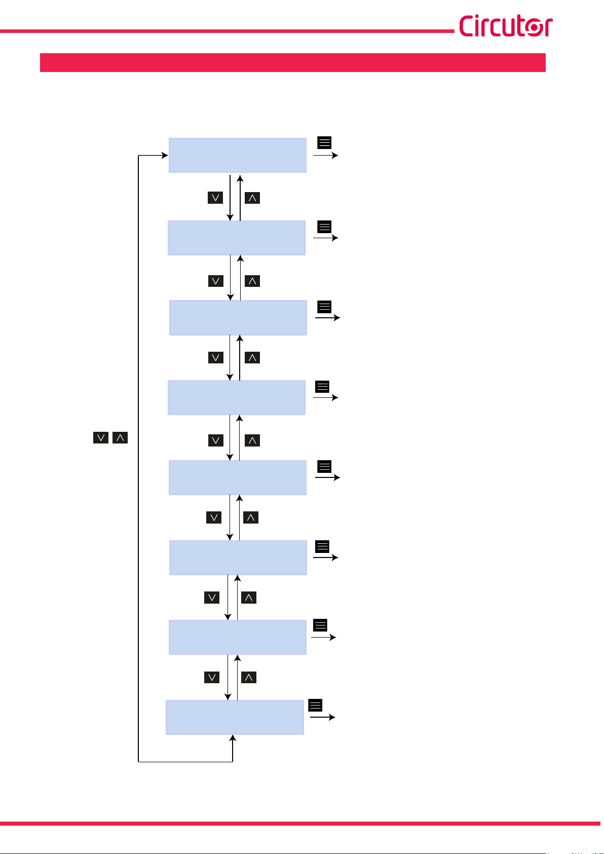
5�- DISPLAY
The parameters shown by the device on the screen are organised into different display menus,
as shown in Figure 38.
MEASURE
DEVICE PROFILE
QUALITY
COMMUNICATIONS
Measures
Device profile
Quality
Communications
DATE/TIME
INFORMATION
ENERGY RATIOS
SETUP MENU
Date
Information
Energy ratios
Configuration menus
Instruction Manual
Figure 38:MYeBOX display menu�
49
Page 50

MYeBOX 150 - MYeBOX 1500
Once the device has nished booting up, the display shows the rst screen of the Measure
display menu, as shown in Figure 39.
VL1 VL2 VL3
230.0 230.0 230.0
Figure 39:Phase-neutral voltage screen, measure menu�
If the device detects a system error, the error screen appears as shown in Figure 40, indicating
the error code. This screen disappears by pressing any key or button on the unit.
SISTEM VERIFIED
CODE ERROR: 0x01FE
Figure 40: Error code screen�
When any phase-neutral voltage exceeds 600 V the following screen appears:
DANGER
OVERVOLTAGE
Figure 41:Overvoltage screen�
This screen does not disappear until the voltage falls below 600 V (phase-neutral) .
50
Instruction Manual
Page 51
MYeBOX 150 - MYeBOX 1500
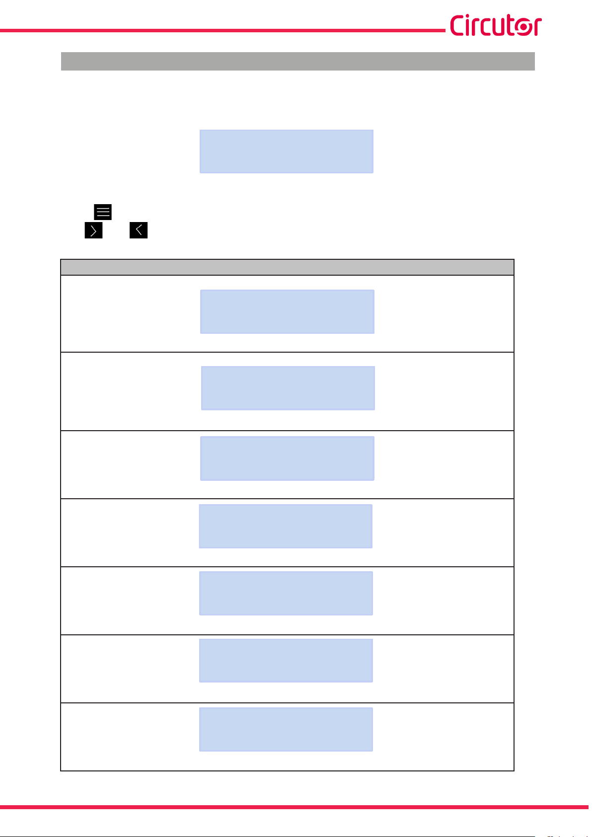
5.1.- DISPLAY MENU: MEASURE
Figure 42 shows the main screen of the Measure display menu, showing all the device’s
measuring parameters.
MEASURE
Figure 42:Measure display menu, main screen�
Press the key to enter the display menu.
Use the and keys to toggle between the different screens.
Table 22: Measure display menu�
Measure display menu
VL1 VL2 VL3
230.0 230.0 230.0
Phase - Neutral Voltages, VL1, VL2 and VL2
VL12 VL23 VL31
398.0 400.0 401.3
Phase - Phase Voltages, VL12, VL23 and VL31
A1 A2 A3
5.00 5.00 5.00
Phase currents, A1, A2 and A3.
kW1 kW2 kW3
11500 11575 11600
Active Power, of each of the phases�
(16)
kvrL1 kvrL2 kvrL3
11500 11575 11600
Inductive Reactive Power, of each of the phases�
kvrC1 kvrC2 kvrC3
11500 11575 11600
Capacitive Reactive Power, of each of the phases�
kVA1 kVA2 kVA3
11500 11575 11600
Apparent Power, of each of the phases�
Instruction Manual
(16)
(16)
(16)
51
Page 52

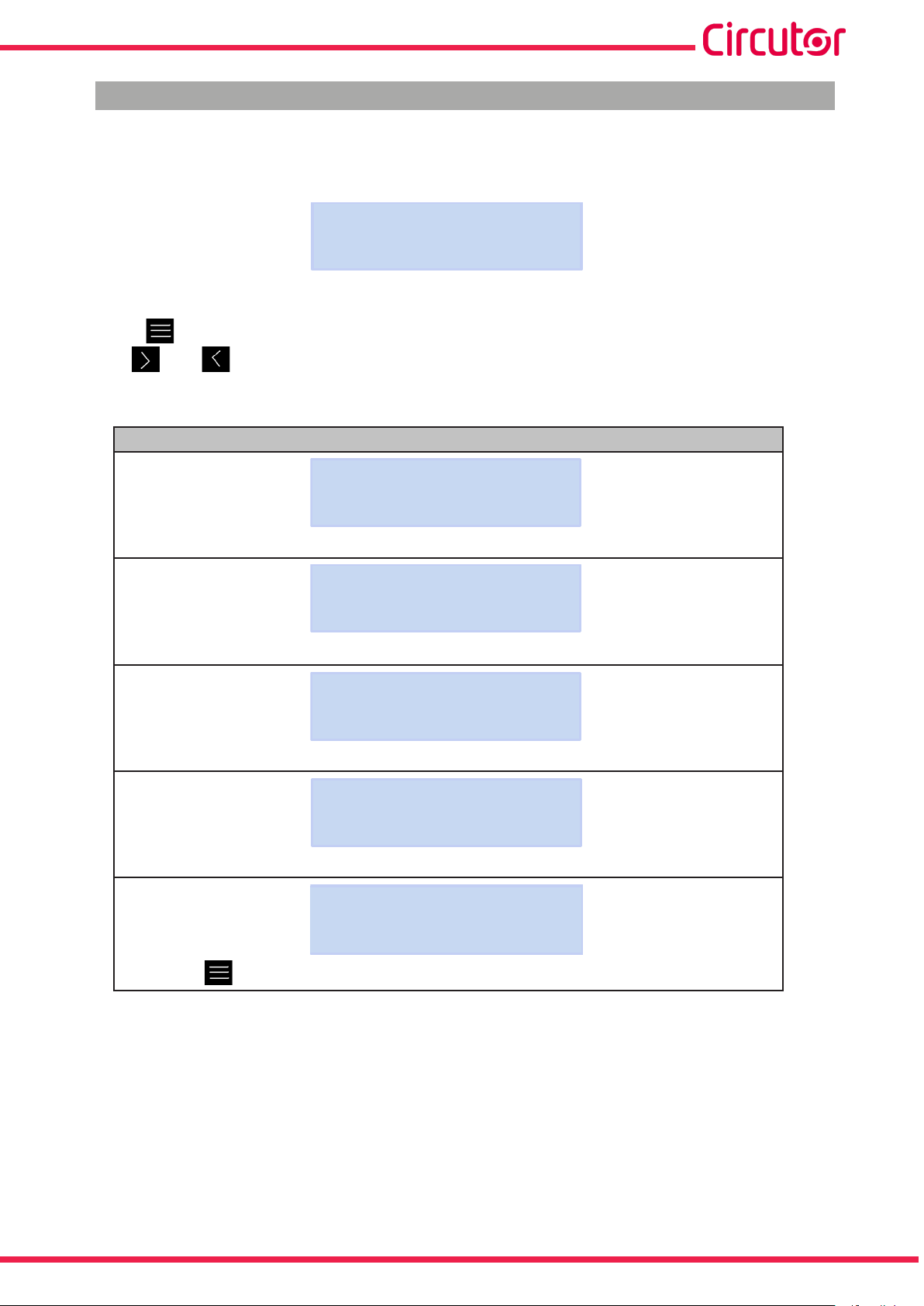
Table 21 (Continued): Measure display menu�
Measure display menu
COS1 COS2 COS3
-0.80 -1.00 -0.50
MYeBOX 150 - MYeBOX 1500
Cos φ, of each of the phases.
(16)
COS l l l PF l l l
1.00 -0.95
Cos φ III and Power Factor III
(16)
kvrC l l l kvrL l l l
34500 34500
Three-phase Capacitive Reactive Power and three-phase Inductive Reactive Power�
kW l l l kVA l l l
34500 33450
Three-phase Active Power and three-phase Apparent Power�
(16)
FREQ kWh l l l
50.00 00999999.999
Three-phase frequency and energy�
(16)
V Kd V Ka
2.340 0.653
Voltage unbalance coefcient (Kd) and voltage asymmetry coefcient (Ka)�
INPUT1 INPUT2
25.349 28.218
Digital inputs
If they have been congured as Status, it shows whether the input is connected (1) or
disconnected (0).
If they have been congured as Meter the meter’s totaliser multiplied by the selected metering
factor is displayed.
MAIN MENU
Press the key to quit the display menu.
(16)
Only consumed values are shown on the display.
52
Instruction Manual
Page 53
MYeBOX 150 - MYeBOX 1500
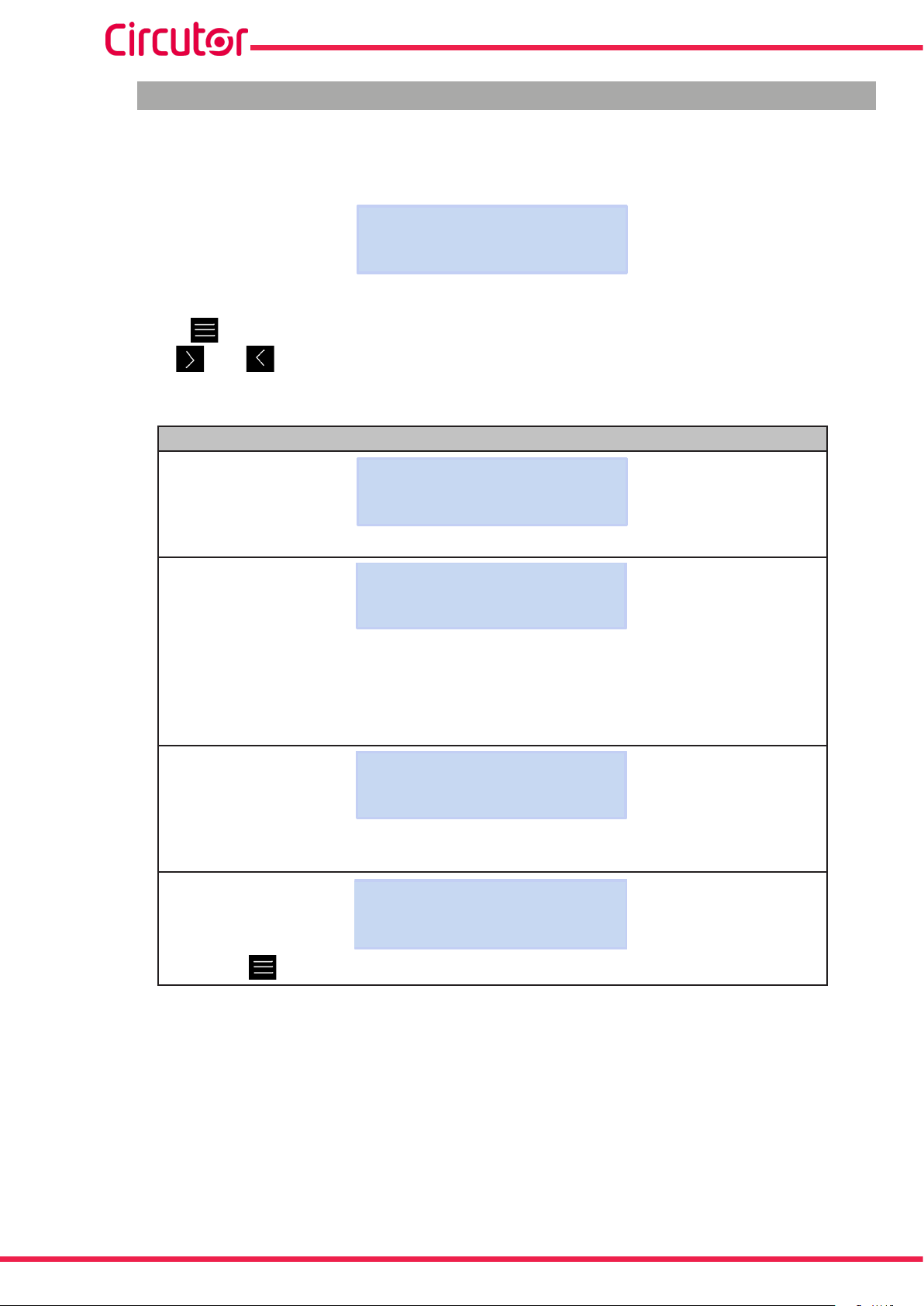
5.2.- DISPLAY MENU: DEVICE PROFILE
Figure 43 shows the main screen of the Device Prole display menu, showing all the device's
prole.
DEVICE PROFILE
Figure 43:Device Prole display menu, main screen.
Press the key to enter the display menu.
Use the and keys to toggle between the different screens.
Table 23: Device Prole display menu.
Device Prole display menu
DEVICE NAME
MYeBOXService
Name of the device, dened in the setup menu.
MEASURE NAME
MEASURE_DEFAULT
Name of the database's current log
CIRCUIT SELECTED
3 PHASES + NEUTRAL
Type of installation, congured on the device�
VL2 VL3 VL1
-I1 I2 I3
Connection conguration for the current and voltage phases.
MAIN MENU
(17)
Press the key to quit the display menu.
(17)
May only be congured in the mobile application.
Instruction Manual
53
Page 54
MYeBOX 150 - MYeBOX 1500
5.3.- DISPLAY MENU: QUALITY
Figure 44 shows the main screen of the Quality display menu, showing all the device's quality
parameters.
QUALITY
Figure 44:Quality display menu, main screen�
Press the key to enter the display menu.
Use the and keys to toggle between the different screens.
Table 24: Quality display menu�
Quality display menu
NOMINAL VOLTAGE
163.00
Rated voltage
SWELL SAG INTERRU
105 113 205
Detected events meter:
SWELL, no. of overvoltages detected.
SAG, no. of gaps detected.
INTERRU, no. of outages detected.
The meters reset every time a new data log is started and when the device restart.
TRANSIENTS
2435
Meter counting the no� of transients detected, resets every time a new data log is
started and when the device restart.
MAIN MENU
54
Press the key to quit the display menu.
Instruction Manual
Page 55

MYeBOX 150 - MYeBOX 1500
3G / 4G IP
5.4.- DISPLAY MENU: COMMUNICATIONS
Figure 45 shows the main screen of the Communications display menu, showing full
information about the device's active communications.
COMMUNICATIONS
Figure 45:Communications display menu, main screen�
Press the key to enter the display menu.
Use the and keys to toggle between the different screens.
Table 25: Communications display menu�
Communications display menu
WIFI CONFIG
ACCESS POINT
Wi-Fi conguration type
WIFI SSID
MYeBOX_083115331025
SSID, Name of the MYeBOX network if Wi-Fi conguration type is Access Point, or
name of the corporate network if the conguration type is Network.
WIFI IP
172.111.255.001
IP of the Wi-Fi network.
WIFI SIGNAL
86 %
Level of Wi-Fi signal, value between 0% and 100%, if Wi-Fi conguration type is
Network.
Note: Screen visible on the MYeBOX 1500 model
Name of the 3G network
Note: Screen visible on the MYeBOX 1500 model
IP of the 3G network
Instruction Manual
3G NETWORK
apn.vodafone.es
3G IP
172.111.255.001
55
Page 56
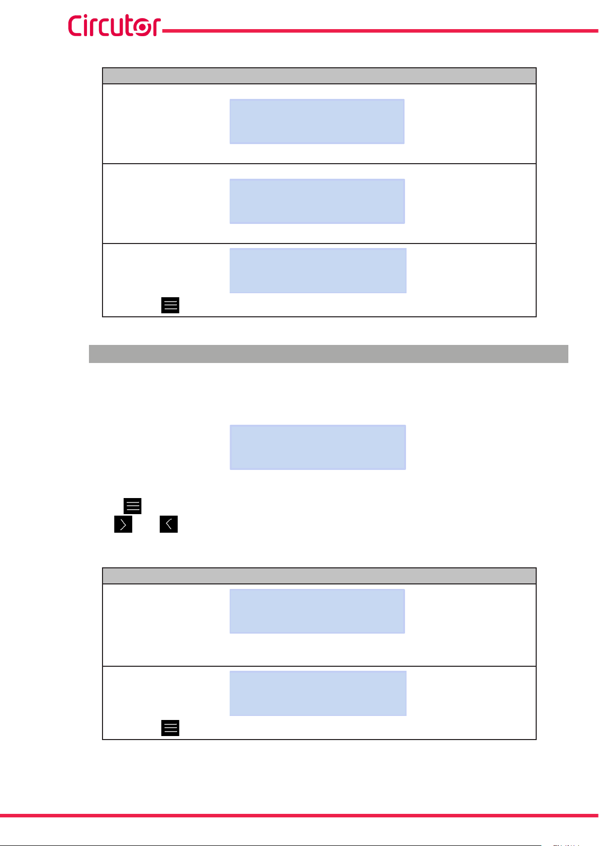
Table 24 (Continued): Communications display menu�
Communications display menu
Note: Screen visible on the MYeBOX 1500 model
3G SIGNAL
86 %
Level of 3G signal, value between 0% and 100%.
Note: Screen visible on the MYeBOX 1500 model
IMEI
357784047309511
IMEI code (International Mobile Station Equipment Identity)
MAIN MENU
MYeBOX 150 - MYeBOX 1500
Press the key to quit the display menu.
5.5.- DISPLAY MENU: DATE/TIME
Figure 46 shows the main screen of the Date/Time display menu, showing the current date
and time.
DATE/TIME
Figure 46:Date/Time display menu, main screen�
Press the key to enter the display menu.
Use the and keys to toggle between the different screens.
Table 26: Date/Time display menu�
Date/Time display menu
56
DATA TIME
05/03/2015 16:00:50
Current date and time� The date can be shown in dd/mm/yyyy format or
mm/dd/yyyy format, based on the option programmed on the mobile application.
MAIN MENU
Press the key to quit the display menu.
Instruction Manual
Page 57
MYeBOX 150 - MYeBOX 1500
5.6.- DISPLAY MENU: INFORMATION
Figure 47 shows the main screen of the Information display menu, showing full information
about the device.
INFORMATION
Figure 47:Information display menu, main screen�
Press the key to enter the display menu.
Use the and keys to toggle between the different screens.
Table 27: Information display menu�
Information display menu
MEMORY SPACE
75 %
Memory space available.
Note: Available memory space is never 100%, not even after complete deletion of the
database, as a new empty database is generated.
BATTERY LEVEL
99 %
Battery charge level
REGISTER CODE
203591F559255F00
ID number of the device
CODE ERROR
0x0006
Code error, 0x0000 indicates that there are no errors on your device.
All possible error codes of the unit are shown in Table 28.
VERSION
000.001.039
Device version
MAIN MENU
Press the key to quit the display menu.
Instruction Manual
57
Page 58

MYeBOX 150 - MYeBOX 1500
Table 28: Code error
Error bit Description Action
0x0000 There is no error
0x0001 Memory (DDR) error
0x0002
0x0004
0x0006
0x0008 Memory (NAND) error
0x0010 3G communications error
0x0020 Wi-Fi communications error
0x0040 UART 1 error
0x0080 UART 2 error
0x0100 Processor error
0x0200 Keyboard error
0x0400 ADC error
0x0800 ADC1 error
0x1000 UART 2 status error
0x11FE Internal error
0x2000 Keyboard conguration error
MicroSD memory error
-
Turn the device off and then on again.
If the problem persists contact the Technical Assistance
Service.
Check that the MicroSD memory card has been inserted
correctly in its slot.
If the problem persists contact the Technical Assistance
Service.
Turn the device off and then on again.
If the problem persists contact the Technical Assistance
Service.
5.7.- DISPLAY MENU: ENERGY RATIOS
Figure 48, shows the main screen of the Energy Ratios menu, displaying all of the device’s
energy ratios.
ENERGY RATIOS
Figure 48: Energy Ratios display menu, main screen�
Press the key to enter the display menu.
Use the and keys to toggle between the different screens.
Table 29: Energy Ratios display menu
Energy Ratios display menu
hourT1+ costT1+
3 5.34567
No� of hours of the active Tariff 1 (Energy Consumed)
Cost per kWh of Tariff 1 (Energy Consumed)
58
KgCO2T1+
280.76544
CO2 emissions of Tariff 1 (Energy Consumed)
Instruction Manual
Page 59

MYeBOX 150 - MYeBOX 1500
Table 29 (Continued) : Energy Ratios display menu
No� of hours of the active Tariff 1 (Energy Generated)
Cost per kWh of Tariff 1 (Energy Generated)
CO2 emissions of Tariff 1 (Energy Generated)
No� of hours of the active Tariff 2 (Energy Consumed)
Cost per kWh of Tariff 2 (Energy Consumed)
Menú de visualización Measure
hourT1- costT1-
2 5.25244
KgCO2T1-
125.85855
hourT2+ costT2+
1 2.32160
KgCO2T2+
150.70044
CO2 emissions of Tariff 2 (Energy Consumed)
hourT2- costT2-
5 7.85165
No� of hours of the active Tariff 2 (Energy Generated)
Cost per kWh of Tariff 2 (Energy Generated)
KgCO2T2-
50.70000
CO2 emissions of Tariff 2 (Energy Generated)
MAIN MENU
Press the key to quit the display menu.
Instruction Manual
59
Page 60

MYeBOX 150 - MYeBOX 1500
6�- CONFIGURATION
The device's conguration is organised into different menus, as shown in Figure 49.
SETUP MENU
MEASURE SETUP
DEVICE PROFILE SETUP
QUALITY SETUP
COMMUNICATIONS SETUP
Measures
Device profile
Quality
Communications
MEMORY SETUP
RESET FACTORY SETUP
SERVICE SETUP
Service
MAIN MENU
Figure 49:MYeBOX conguration menu.
Memory
Factory setting
(18)
(8)
Display menus
60
(18)
The Service Setup menu is the service menu of the device for internal use, and is of no use
to the MYeBOX user.
Instruction Manual
Page 61

MYeBOX 150 - MYeBOX 1500
If from any setup menu screen no key is pressed for 5 minutes, the device quits the setup menu
and returns to the Phase-Neutral Voltages screen of the Measure display menu.
Note: Setup menu changes must be made while data logging is off.
6.1.- SETUP MENU: MEASURE SETUP
Figure 50 shows the main screen of the Measure setup menu, where the device’s measurement
parameters are congured.
MEASURE SETUP
Figure 50:Measure setup menu, main screen�
Press the key to enter the setup menu.
6�1�1�- RATED VOLTAGE
This screen is used to congure the rated phase - neutral voltage value.
NOMINAL VOLTAGE
OOO230.50
Press the key to enter edit mode.
Use the and keys to write or change the value of the blinking digit.
When the value on the screen is as desired, use the and keys to move the editing cursor.
Minimum conguration value: (Rated Voltage / Voltage Ratio) ≥ 50.
Maximum conguration value: (Rated Voltage / Voltage Ratio) ≤ 1000.
Maximum possible voltage ratio: 9999.
Note: The voltage ratio is the ratio between the primary and secondary voltage.
Press the key to conrm.
Use the and keys to toggle between the menu’s setup screens.
Instruction Manual
61
Page 62

MYeBOX 150 - MYeBOX 1500
6�1�2�- PRIMARY VOLTAGE
This screen is used to congure the primary winding of the voltage transformer.
PRIMARY VOLTAGE
000001
Press the key to enter edit mode.
Use the and keys to write or change the value of the blinking digit.
When the value on the screen is as desired, use the and keys to move the editing cursor.
Minimum conguration value: 1 V.
Maximum conguration value: 500000 V.
Press the key to conrm.
Use the and keys to toggle between the menu’s setup screens.
6�1�3�- SECONDARY VOLTAGE
This screen is used to congure the secondary winding of the voltage transformer.
SECONDARY VOLTAGE
001.5
Press the key to enter edit mode.
Use the and keys to write or change the value of the blinking digit.
When the value on the screen is as desired, use the and keys to move the editing cursor.
Minimum conguration value: 1.0 V.
Maximum conguration value: 999.9 V.
62
Press the key to conrm.
Use the and keys to toggle between the menu’s setup screens.
Instruction Manual
Page 63

MYeBOX 150 - MYeBOX 1500
6�1�4�- PHASE CLAMP SCALE
This screen is used to select the scale of the clamps selected for measuring the phase.
Note: If the clamp only has one scale, this parameter cannot be edited.
PHASE CLAMP SCALE
LOW
Press the key to enter edit mode.
Use the keys and to browse the different options:
Hi, MEDIUM or LOW. (See “3.5.- CURRENT CLAMPS”).
Press the key to conrm the option selected.
Use the and keys to toggle between the menu’s setup screens.
6�1�5�- PRIMARY WINDING OF THE CURRENT TRANSFORMER
Note: This parameter is only shown when a CPG-5 clamp is connected.
This screen is used to congure the primary winding of the current transformer, for the phase
measurement.
PHASE CURRENT TRANSF
05000
Press the key to enter edit mode.
Use the and keys to write or change the value of the blinking digit.
When the value on the screen is as desired, use the and keys to move the editing cursor.
Minimum conguration value: 1 A.
Maximum conguration value: 10000 A.
Press the key to conrm.
Use the and keys to toggle between the menu’s setup screens.
Instruction Manual
63
Page 64

MYeBOX 150 - MYeBOX 1500
6�1�6�- NEUTRAL CLAMP SCALE
This screen is used to select the scale of the clamp selected for measuring the neutral.
Note: If the clamp only has one scale, this parameter cannot be edited.
NEUTRAL CLAMP SCALE
LOW
Press the key to enter edit mode.
Use the keys and to browse the different options:
Hi, MEDIUM or LOW. (See “3.5.- CURRENT CLAMPS”).
Press the key to conrm the option selected.
Use the and keys to toggle between the menu’s setup screens.
6�1�7�- PRIMARY WINDING OF THE NEUTRAL CURRENT TRANSFORMER
Note: This parameter is only shown when a CPG-5 clamp is connected.
This screen is used to congure the primary winding of the current transformer, for measuring
the neutral.
NEUTR CURRENT TRANSF
05000
Press the key to enter edit mode.
Use the and keys to write or change the value of the blinking digit.
When the value on the screen is as desired, use the and keys to move the editing cursor.
Minimum conguration value: 1 A.
Maximum conguration value: 10000 A.
Press the key to conrm.
64
Use the and keys to toggle between the menu’s setup screens.
Instruction Manual
Page 65
MYeBOX 150 - MYeBOX 1500
LEAK
6�1�8�- CLAMP SCALE FOR MEASURING THE LEAKAGE CURRENT, ILeak
Note: Conguration parameter available for the MYeBOX 1500 model.
This screen is used to select the scale of the clamp selected for measuring the leakage current.
Note: If the clamp only has one scale, this parameter cannot be edited.
LEAK CLAMP SCALE
LOW
Press the key to enter edit mode.
Use the keys and to browse the different options:
Hi, MEDIUM or LOW. (See “3.5.- CURRENT CLAMPS”).
Press the key to conrm the option selected.
Use the and keys to toggle between the menu’s setup screens.
6�1�9�- PRIMARY WINDING OF THE LEAKAGE CURRENT TRANSFORMER
Note: Conguration parameter available for the MYeBOX 1500 model.
This screen is used to congure the primary winding of the current transformer, for measuring
the leakage current.
CURRENT TRANSF
05000
Press the key to enter edit mode.
Use the and keys to write or change the value of the blinking digit.
When the value on the screen is as desired, use the and keys to move the editing cursor.
Minimum conguration value: 1 A.
Maximum conguration value: 10000 A.
Press the key to conrm.
Use the and keys to toggle between the menu’s setup screens.
Instruction Manual
65
Page 66

MYeBOX 150 - MYeBOX 1500
SAVE
6�1�10�- FREQUENCY
This screen is used to select the operating frequency.
FREQ HZ
50.00
Press the key to enter edit mode.
Use the and keys to browse the different options:
50.00, 50 Hz.
60.00, 60 Hz,
Press the key to conrm the option selected.
Use the and keys to toggle between the menu’s setup screens.
6�1�11�- SAVE
Press the key to save the changes and to go to the main screen of the Measure setup
menu.
Use the and keys to toggle between the menu’s setup screens.
6�1�12�- EXIT
Press the key to exit to the main screen of the Measure setup menu without saving mod-
ied values.
Use the and keys to toggle between the menu’s setup screens.
66
Instruction Manual
Page 67

MYeBOX 150 - MYeBOX 1500
6.2.- SETUP MENU: DEVICE PROFILE SETUP
Figure 51 shows the main screen of the Device Prole setup menu where the device's prole
can be congured.
DEVICE PROFILE SETUP
Figure 51:Device Prole setup menu, main screen.
Press the key to enter the setup menu.
6�2�1�- NAME OF THE DEVICE
This screen is used to congure the name used to identify the device.
DEVICE NAME
MYeBOXService
Press the key to enter edit mode.
Use the and keys to write or change the value of the blinking digit.
When the value on the screen is as desired, use the and keys to move the editing cursor.
Press the key to conrm.
Use the and keys to toggle between the menu's setup screens.
6�2�2�- MEASUREMENT NAME
This screen is used to congure the name under which to save the data log in the database. All
the measurements will be displayed in the application with the recording start date next to the
name of the measurement.
MEASURE NAME
MEASURE_DEFAULT
Press the key to enter edit mode.
Use the and keys to write or change the value of the blinking digit.
When the value on the screen is as desired, use the and keys to move the editing cursor.
Press the key to conrm.
Use the and keys to toggle between the menu's setup screens.
Instruction Manual
67
Page 68
MYeBOX 150 - MYeBOX 1500
SAVE
6�2�3�- TYPE OF INSTALLATION
This screen is used to congure the installation type.
SELECT CIRCUIT
3 PHASES + NEUTRAL
Press the key to enter edit mode.
Use the keys and to browse the different options:
1 PHASE + NEUTRAL, Single-phase network measurement, phase to neutral, with a
2-wire connection.
2 PHASES, Single-phase network measurement, phase to phase, with a 2-wire connec-
tion.
2 PHASES + NEUTRAL, Two-phase network measurement with a 3-wire connection.
3 PHASES, Three-phase network measurement with a 3-wire connection.
3 PHASES + NEUTRAL, Three-phase network measurement with a 4-wire connection.
ARON, Three-phase network measurement with a 3-wire connection and an ARON con-
nection.
Press the key to conrm the option selected.
Use the and keys to toggle between the menu’s setup screens.
6�2�4�- SAVE
Press the key to save the changes and to go to the main screen of the Device Prole setup
menu.
Use the and keys to toggle between the menu’s setup screens.
6�2�5�- EXIT
Press the key to exit to the main screen of the Device Prole setup menu without saving
modied values.
Use the and keys to toggle between the menu’s setup screens.
68
Instruction Manual
Page 69

MYeBOX 150 - MYeBOX 1500
6.3.- SETUP MENU: QUALITY SETUP
Figure 52 shows the main screen of the Quality setup menu, where the device's quality
parameters are congured.
QUALITY SETUP
Figure 52:Quality setup menu, main screen�
Press the key to enter the setup menu.
6�3�1�- OVERVOLTAGE, SWELL
This screen is used to congure the threshold value for logging an overvoltage, as a percentage
of the rated voltage value.
SOBRETENSION / SWELL
110 %
Press the key to enter edit mode.
Use the and keys to write or change the value of the blinking digit.
When the value on the screen is as desired, use the and keys to move the editing cursor.
Minimum conguration value: 100%
Maximum conguration value: 150%
Note: Set the value to 0 to stop recording overvoltages.
Press the key to conrm.
Use the and keys to toggle between the menu's setup screens.
6�3�2�- GAP, SAG
This screen is used to congure the threshold value for logging gaps, as a percentage of the
rated voltage value.
HUECO / SAG
090 %
Press the key to enter edit mode.
Use the and keys to write or change the value of the blinking digit.
When the value on the screen is as desired, use the and keys to move the editing cursor.
Instruction Manual
69
Page 70

MYeBOX 150 - MYeBOX 1500
Minimum conguration value: 50%
Maximum conguration value: 97%
Note: Set the value to 0 to stop recording gaps.
Press the key to conrm.
Use the and keys to toggle between the menu's setup screens.
6�3�3�- OUTAGE, INTERRUPTION
This screen is used to congure the threshold value for logging outages, as a percentage of the
rated voltage value.
CORTE / INTERRUPTION
010%
Press the key to enter edit mode.
Use the and keys to write or change the value of the blinking digit.
When the value on the screen is as desired, use the and keys to move the editing cursor.
Minimum conguration value: 1%
Maximum conguration value: 20%
Note: Set the value to 0 to stop recording outages.
Press the key to conrm.
Use the and keys to toggle between the menu's setup screens.
6�3�4�- TRANSIENTS, DISTURB
This screen is used to congure the distortion level coefcient for the detection of transients.
TRANSITORIO/DISTURB
002.0
70
Press the key to enter edit mode.
Use the and keys to write or change the value of the blinking digit.
When the value on the screen is as desired, use the and keys to move the editing cursor.
Minimum conguration value: 1.0
Maximum conguration value: 100.0
Note : Recommended value 5.0
Note: Set the value to 0 to stop detecting transients.
Instruction Manual
Page 71

MYeBOX 150 - MYeBOX 1500
SAVE
Press the key to conrm.
Use the and keys to toggle between the menu’s setup screens.
6�3�5�- SAVE
Press the key to save the changes and to go to the main screen of the Quality setup menu.
Use the and keys to toggle between the menu’s setup screens.
6�3�6�- EXIT
Press the key to exit to the main screen of the Quality setup menu without saving modied
values.
Use the and keys to toggle between the menu’s setup screens.
6.4.- SETUP MENU: COMMUNICATIONS SETUP
Figure 53 shows the main screen of the Communications setup menu, where the device's
communication parameters are congured.
COMMUNICATIONS SETUP
Figure 53:Communication setup menu, main screen�
Press the key to enter the setup menu.
6�4�1�- Wi-Fi CONFIGURATION
This screen is used to select the type of Wi-Fi conguration.
Press the key to enter edit mode.
Use the keys and to browse the different options:
Instruction Manual
WIFI COMM
ACCESS POINT
71
Page 72

MYeBOX 150 - MYeBOX 1500
NETWORK, Select this option when the unit is going to connect to a previously created
corporate Wi-Fi network.
ACCESS POINT, After selecting this option, the device generates a Wi-Fi network so the
user can connect from the mobile application.
Press the key to conrm the option selected.
Use the and keys to toggle between the menu's setup screens.
6�4�2�- SSID
Note: This conguration parameter cannot be edited if ACCESS POINT was selected for the “6.4.1.-
Wi-Fi CONFIGURATION” parameter.
This screen is used to congure the SSID (Service Set Identier), or the name of the corporate
network.
WIFI SSID
MYeBOX_083115331025
Press the key to enter edit mode.
Use the and keys to write or change the value of the blinking digit.
When the value on the screen is as desired, use the and keys to move the editing cursor.
Press the key to conrm.
Use the and keys to toggle between the menu's setup screens.
6�4�3�- WPS
Note: This conguration parameter cannot be edited if ACCESS POINT was selected for the “6.4.1.-
WI-FI CONFIGURATION” parameter.
This screen is used to select WPS activation, which is used to easily connect the device to
networks.
To establish the connection via WPS, activate the WPS button on the router to which the My-
eBOX will be connected. The router will be prepared to accept new devices for 1 or 2 minutes
after you press this button.
This is when WPS must be activated in the MyeBOX.
72
ACTIVATE WPS
YES
Press the key to enter edit mode.
Use the keys and to browse the different options:
YES, WPS activated.
Instruction Manual
Page 73
MYeBOX 150 - MYeBOX 1500
MYeBOX_083115331025
********************
NO, WPS deactivated.
Press the key to conrm the option selected.
Note: The device activates the WPS after the conguration is saved (“6.4.10.- SAVE”).
Use the and keys to toggle between the menu's setup screens.
6�4�4�- PASSWORD
Note: This conguration parameter cannot be edited if ACCESS POINT was selected for the “6.4.1.-
Wi-Fi CONFIGURATION” parameter or YES was selected for the “6.4.3.- WPS” parameter
This screen is used to congure the Wi-Fi network password.
WIFI PASSWORD
Press the key to enter edit mode.
Use the and keys to write or change the value of the blinking digit.
When the value on the screen is as desired, use the and keys to move the editing cursor.
Maximum number of characters: 32.
Press the key to conrm.
Use the and keys to toggle between the menu's setup screens.
6�4�5�- ENABLING 3G COMMUNICATIONS
Note: Conguration parameter available for the MYeBOX 1500 model.
This screen is used to select whether to enable 3G communications.
3G COMMUNICATION
ENABLE
Press the key to enter edit mode.
Use the keys and to browse the different options:
ENABLE, 3G communications enabled.
DISABLE, 3G communications disabled.
Press the key to conrm the option selected.
Use the and keys to toggle between the menu's setup screens.
Instruction Manual
73
Page 74

MYeBOX 150 - MYeBOX 1500
6�4�6�- APN, ACCESS POINT NAME
Note: Conguration parameter available for the MYeBOX 1500 model.
Note: This conguration parameter cannot be edited if DISABLE was selected for the “6.4.5.- EN-
ABLING 3G COMMUNICATIONS” parameter.
This screen is used to congure the name of the APN for 3G communications.
APN NAME
VODAFONE
Press the key to enter edit mode.
Use the and keys to write or change the value of the blinking digit.
When the value on the screen is as desired, use the and keys to move the editing cursor.
Press the key to conrm.
Use the and keys to toggle between the menu's setup screens.
6�4�7�- APN, USER
Note: Conguration parameter available for the MYeBOX 1500 model.
Note: This conguration parameter cannot be edited if DISABLE was selected for the “6.4.5.- EN-
ABLING 3G COMMUNICATIONS” parameter.
This screen is used to congure the APN user for 3G communications.
APN USER
TSW52
Press the key to enter edit mode.
Use the and keys to write or change the value of the blinking digit.
74
When the value on the screen is as desired, use the and keys to move the editing cursor.
Press the key to conrm.
Use the and keys to toggle between the menu's setup screens.
Instruction Manual
Page 75

MYeBOX 150 - MYeBOX 1500
********************
6�4�8�- APN, PASSWORD
Note: Conguration parameter available for the MYeBOX 1500 model.
Note: This conguration parameter cannot be edited if DISABLE was selected for the “6.4.5.- EN-
ABLING 3G COMMUNICATIONS” parameter.
This screen is used to congure the APN password for 3G communications.
APN PASSWORD
Press the key to enter edit mode.
Use the and keys to write or change the value of the blinking digit.
When the value on the screen is as desired, use the and keys to move the editing cursor.
Maximum number of characters: 32.
Press the key to conrm.
Use the and keys to toggle between the menu’s setup screens.
6�4�9�- PIN
Note: Conguration parameter available for the MYeBOX 1500 model.
Note: This conguration parameter cannot be edited if DISABLE was selected for the “6.4.5.- EN-
ABLING 3G COMMUNICATIONS” parameter.
This screen is used to congure the PIN code for 3G communications.
3G PIN
****
Press the key to enter edit mode.
Use the and keys to write or change the value of the blinking digit.
When the value on the screen is as desired, use the and keys to move the editing cursor.
Press the key to conrm.
Use the and keys to toggle between the menu's setup screens.
Instruction Manual
75
Page 76

MYeBOX 150 - MYeBOX 1500
SAVE
6�4�10�- SAVE
Press the key to save the changes and to go to the main screen of the Communications
setup menu.
Use the and keys to toggle between the menu’s setup screens.
6�4�11�- EXIT
Press the key to exit to the main screen of the Communications setup menu without sav-
ing modied values.
Use the and keys to toggle between the menu’s setup screens.
6.5.- SETUP MENU: MEMORY SETUP
Figure 54, shows the main screen of the Memory setup menu, where the memory for storing
the database is congured.
MEMORY SETUP
Figure 54: Memory setup menu, main screen�
Press the key to enter the setup menu.
6�5�1�- COMPLETE DELETION OF THE DATABASE
This screen is used to choose whether to delete the database completely.
FORMAT MEMORY
Press the key to enter edit mode.
Use the keys and to browse the different options:
NO, the database will not be completely deleted.
YES, the database will be completely deleted.
76
NO
Instruction Manual
Page 77

MYeBOX 150 - MYeBOX 1500
SAVE
Press the key to conrm the option selected.
Use the and keys to toggle between the menu’s setup screens.
6�5�2�- SAVE
Press the key to begin deletion of the database.
While the deletion is being performed, the following screen will be shown:
SD FORMATTING ....
At the end of the deletion process, different messages can appear, depending on the result:
SD FORMAT DONE, if the deletion has been correctly performed.
SD NOT DETECTED, if the device cannot detect the memory.
SD FORMAT ERROR, if the deletion has not been correctly performed.
The messages disappear after 5 seconds and the unit skips to the main screen of the Memory
setup menu.
Use the and keys to toggle between the menu’s setup screens.
6�5�3�- EXIT
Press the key to exit to the main screen of the Memory setup menu without saving modi-
ed values.
Use the and keys to toggle between the menu’s setup screens.
Instruction Manual
77
Page 78

MYeBOX 150 - MYeBOX 1500
SAVE
6.6.- SETUP MENU: RESET FACTORY SETUP
Figure 55 shows the main screen of the Reset Factory setup menu where the default values
of the unit can be loaded.
RESET FACTORY SETUP
Figure 55: Reset facvtory setup menu, main screen�
Press the key to enter the setup menu.
6�6�1�- LOADING THE DEFAULT CONFIGURATION�
This screen is used to select whether to load the default conguration in the device, i.e. the
original factory settings.
RESET FACTORY
NO
Press the key to enter edit mode.
Use the keys and to browse the different options:
NO, the default conguration will not be loaded.
YES, the default conguration will be loaded.
Press the key to conrm the option selected.+
Use the and keys to toggle between the menu’s setup screens.
6�6�2�- SAVE
Press the key to start loading the default conguration and skip to the main screen of the
Reset Factory setup menu.
Use the and keys to toggle between the menu’s setup screens.
78
Instruction Manual
Page 79

MYeBOX 150 - MYeBOX 1500
6�6�3�- EXIT
Press the key to exit to the main screen of the Reset Factory setup menu without saving
modied values.
Use the and keys to toggle between the menu’s setup screens.
Instruction Manual
79
Page 80

MYeBOX 150 - MYeBOX 1500
7�- WIRELESS COMMUNICATIONS
The device has the following wireless communications:
MYeBOX 150 model:
Wi-Fi communications
MYeBOX 1500 model:
Wi-Fi communications
3G communications
7.1.- USAGE ENVIRONMENT AND HEALTH
Wireless communications emit radio frequency electromagnetic energy, like other radio devices.
Because wireless communications operate under the guidelines found in radio frequency standards and recommendations, they are safe for users to use.
In some settings and situations the use of wireless communications may be restricted by the
building's owner of representatives of the organisation.
These may include:
Use of wireless connections on board aircraft, in hospitals or near service stations, blasting areas, medical implants or electronic medical devices implanted in the human body
(pacemakers, etc.).
In any other setting where the risk of interference with other devices or services is a hazard.
If you are not sure of the applicable usage policy for wireless devices in a specic organisation
(airport, hospital, etc.) we recommend requesting permission to use wireless communications.
80
Instruction Manual
Page 81

MYeBOX 150 - MYeBOX 1500
7.2.- LOCATION OF THE ANTENNAS
The device has two antennas for Wi-Fi and 3G connections.
3G ( MYeBOX 1500 )
Wi-Fi
Figure 56:Location of the wireless antennas�
The antennas have a standard connector so they can be exchanged for larger ones if the application requires greater coverage.
7.3.- Wi-Fi COMMUNICATIONS
Wi-Fi is one of the most widely-used wireless technologies today, used to connect electronic
devices and exchange information between them without a physical connection.
The MYeBOX has Wi-Fi communications over the 2.4 GHz band, in accordance with the IEEE
802.11b, IEEE 802.11g and IEEE 802.11n standards.
Wi-Fi communications can be congured through the mobile application or by using the device's display. See “6.4.- SETUP MENU: COMMUNICATIONS SETUP” and “5.4.- DISPLAY MENU:
COMMUNICATIONS”.
Table 30: Security features of the Wi-Fi communications�
Security features of the Wi-Fi communications
Security protocol WPA2
SSL-encrypted communications via the web service
Using the API via the web services requires basic authentication�
Instruction Manual
81
Page 82
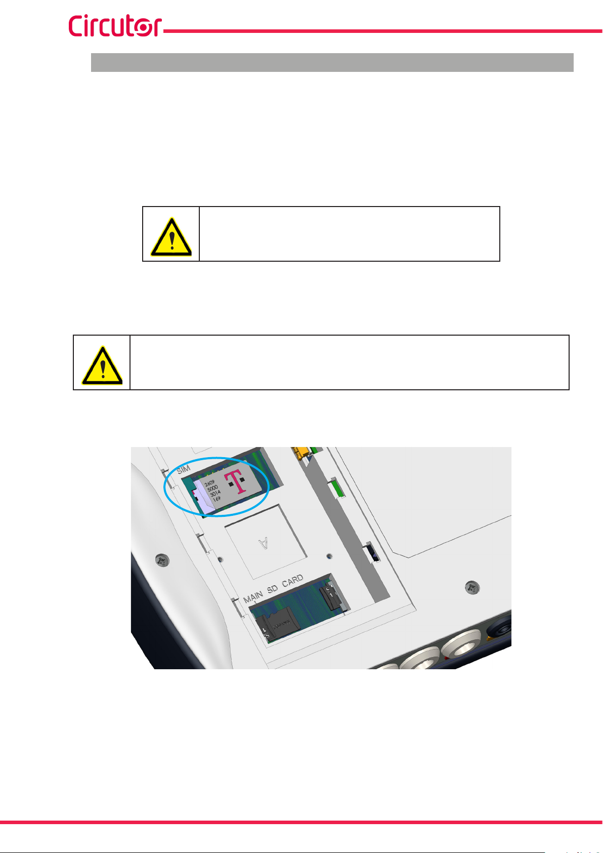
MYeBOX 150 - MYeBOX 1500
7.4.- 3G COMMUNICATIONS (MYeBOX 1500 model)
The MYeBOX 1500 model has 3G communications, so the device can be connected and exchange data with other mobile devices without a Wi-Fi connection.
The only thing required is a SIM card.
3G communications can be congured through the mobile application or by using the device's
display. See “6.4.- SETUP MENU: COMMUNICATIONS SETUP” and “5.4.- DISPLAY MENU: COM-
MUNICATIONS”.
Continued use of 3G can reduce battery use.
Note: Only 3G cards can be used with the device.
7�4�1�- INSERTING THE SIM CARD�
To avoid electric shocks, disconnect the measuring and power supply terminals
before opening the cover.
Do not use the device without the cover in place.
The SIM card is located under the battery. See Figure 57. To remove it, follow the steps indicated in section “3.2.- BATTERY INSTALLATION”.
82
Figure 57:Location of the SIM card�
Instruction Manual
Page 83

MYeBOX 150 - MYeBOX 1500
8�- MOBILE APPLICATION MYeBOX
The device has the MYeBOX mobile application, which allows users to wirelessly connect to
the devices using Wi-Fi or 3G communications (MYeBOX 1500 model) and:
Fully congure the device.
Display all parameters in real time, both numerically and graphically.
View wave shapes.
Download the data log les stored on the MicroSD memory.
Program e-mail warnings when alarms occur.
The MYeBOX application is compatible with iOS and Android and there are versions for smart-
phones and tablets.
9�- MYeBOX Cloud
The device has a cloud application, MYeBOX Cloud, where users can send all the data logged
on the MicroSD memory (see “4.8.2. MicroSD MEMORY”) to be searched and analysed.
10�- SOFTWARE UPDATE
The device software can be updated in two ways:
Through a USB.
Through the MYeBOX mobile application.
Note: Before updating the software, a backup copy of the device’s data (in a le or by saving it
in the Cloud) should be made, since if an anomaly is detected, the database will be automatically formatted.
10.1.- UPDATING THROUGH USB
With MYeBOX switched on:
1�- Connect the device to a PC with the µUSB cable.
2�-The MYeBOX appears as a mass storage unit in the PC explorer.
3�- In the MYeBOX copy the update le (rmware_myeBOX.bin)
4�- After copying the le, disconnect the MYeBOX from the PC.
5�- Restart the MYeBOX; the unit will be updated as soon as it starts up again.
Note: After updating the MYeBOX, it will be automatically restarted.
Instruction Manual
83
Page 84

MYeBOX 150 - MYeBOX 1500
10.2.- UPDATING THROUGH THE MOBILE APPLICATION
With MYeBOX switched on:
1�- Open the MYeBOX mobile application.
2�- If there is a new version of the unit, the application indicates this in the Setup / Firm-
ware menu. And asks the user if they want to update the unit.
3�- If the user conrms the update, it is started automatically.
Note: After updating the MYeBOX, it will be automatically restarted.
84
Instruction Manual
Page 85
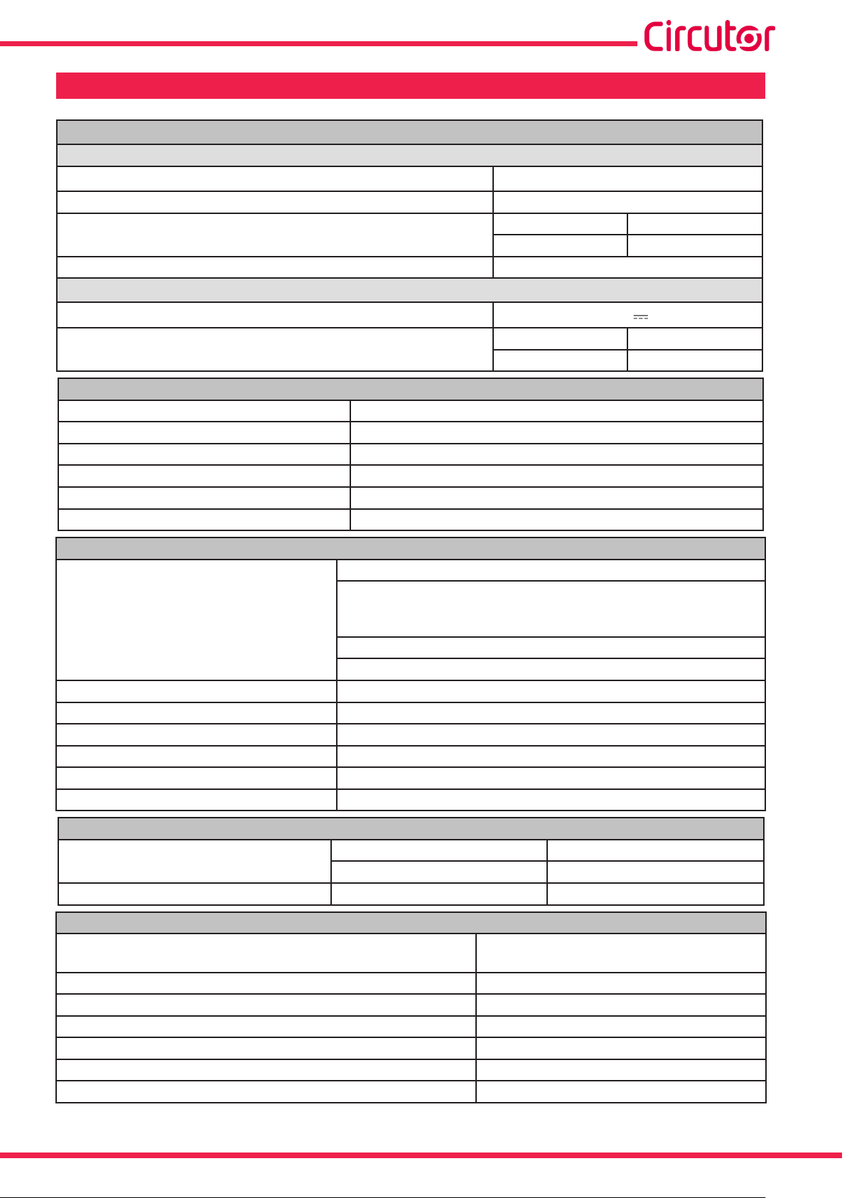
MYeBOX 150 - MYeBOX 1500
11�- TECHNICAL FEATURES
Power supply (AC power supply adaptor)
Input
Rated voltage 100 ... 240 V ~
Frequency 47 ... 63 Hz
Consumption
Installation category CAT II 300 V
Output
Rated voltage
Consumption
Voltage measurement circuit
Voltage measurement margin 10 ...600 V ~ (PH-N)
Frequency measurement margin 42.5 ... 69 Hz
Input impedance 2.4 MΩ
Minimum measurement voltage (Vstart) 10 V ~
Maximum voltage input consumption 0.15 VA
Installation category CAT III 600 V
MYeBOX 150 MYeBOX 1500
22... 28 VA 25... 31 VA
9 V
MYeBOX 150 MYeBOX 1500
18 W 20 W
Current measurement circuit
Phase and neutral current measurement
Clamps: CPG-5, CPG-100, CPRG-500, CPRG-1000,
Type of clamp / Transformer
CPG-200/2000, FLEX-Rxxx,
Transformer with 250 mA or 333 mV output
Leakage current measurement (MYeBOX 1500 model)
CFG-5, CFG-10, WG type transformers
Nominal current (In) According to clamp Table 5 and Table 6
Current measurement margin 1 ... 200 In %
Maximum current, impulse < 1s 3*In A
Minimum measurement current(Istart) According to clamp Table 5 and Table 6
Maximum current input consumption 0.0004 VA
Installation category CAT III 600 V
Frequency of sampling
MYeBOX 150
50 Hz 60 Hz
44.8 kHz 53.76 kHz
MYeBOX 1500 57.6 kHz 69.12 kHz
(19)
Class 0.2 (10 ...600 V~) (IEC 61557-12)
Clase A (23 ...345 V~) (IEC 61000-4-30)
Voltage measurement (Ph-N)
Accuracy of measurements
(20)
Current measurement Class 0.2 (1%...200% In) (IEC 61557-12)
Measurement of active and apparent power (Vn 230/110 V~) Class 0.5 ± 1 digit (IEC 61557-12)
Reactive power measurement (Vn 230/110 V~) Class 1 ± 1 digit (IEC 61557-12)
Active energy measurement Class 0.5S (IEC 62053-22)
Reactive energy measurement Class 1 (IEC 62053-23)
Frequency measurement Clase A ( 42.5 ... 69 Hz) (IEC 61000-4-30)
Instruction Manual
85
Page 86

MYeBOX 150 - MYeBOX 1500
(Continued) Accuracy of measurements
(19)
Power factor measurement Class 0.5 (IEC 61557-12)
Voltage THD measurement Class I (IEC 61000-4-7)
Voltage harmonics (up to 50th order) Class I (IEC 61000-4-7)
Current THD measurement Class I (IEC 61000-4-7)
Current harmonics (up to 50th order) Class I (IEC 61000-4-7)
Pinst Flicker 3 % (IEC 61000-4-15)
Pst Flicker 5 % (0.2 ... 10Pst) (IEC 61000-4-15)
Voltage unbalance Class A (IEC 61000-4-30)
Voltage asymmetry Class A (IEC 61000-4-30)
Current unbalance Class A (IEC 61000-4-30)
Current asymmetry Class A (IEC 61000-4-30)
(19)
Accuracy is given by the following measurement conditions for input 2V: exclusion of errors produced by the
clamps and external voltage transformers, with a range in temperature of 5 ... 45 ºC and power factor 0 ... 1.
(20)
Depending on model.
Transistor digital outputs (MYeBOX 1500 model)
Quantity 2
Type Transistor
Maximum voltage 48 V
Maximum current 90 mA
Digital inputs (MYeBOX 1500 model)
(21)
Quantity 2
Type Potential-free contact
Insulation 2.7 kV
Maximum short-circuit current 5 mA
Maximum voltage in open circuit
4 ... 9 V
Maximum frequency 100 Hz
(21)
Must be connected to SELV circuit.
Wi-Fi communications
Band 2.4 GHz
Standards IEEE 802.11 b / g / n
Output power 20 dBm
Effective radiated power (ERP) < 57 dBm
Effective isotropic radiated power
(EIRP)
17 dBm
Power of the transmitter 17 dBm
Specic absortion rate (SAR) 0.08 W/Kg
86
3G Communications (MYeBOX 1500 model)
Networks : MYeBOX 1500-3G
Networks : MYeBOX 1500-3G_CA
Networks : MYeBOX 1500-3G_XP
Maximum output power
UMTS/HSPA: 850/900/1900/2100 MHz
GSM/GPRS/EDGE: 850/900/1800/1900 MHz
UMTS/HSPA/HSPA+: 850/1900/2100 MHz
GSM/GPRS/EDGE: 850/900/1800/1900 MHz
UMTS/HSPA/HSPA+: 900/2100 MHz
GSM/GPRS/EDGE: 850/900/1800/1900 MHz
UMTS/3G (Power Class 3): 24 dBm
GSM850/900 (Power Class 4): 33 dBm
GSM1800/1900 (Power Class 1): 30 dBm
Instruction Manual
Page 87
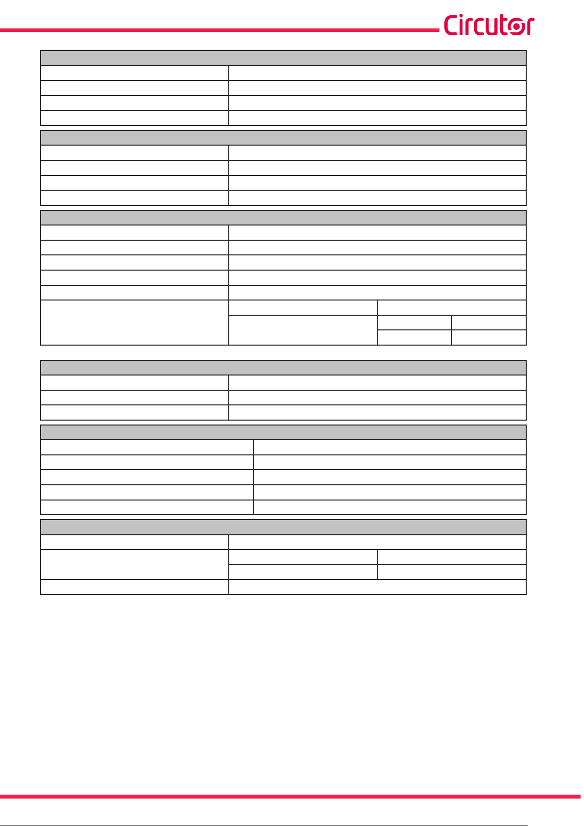
MYeBOX 150 - MYeBOX 1500
User interface
Display 20 alphanumeric characters x 2 lines
Keypad 5 keys, 2 buttons
LED MYeBOX 150: 14 LEDs, MYeBOX 1500: 21 LEDs
Connectivity μUSB
Internal battery
Type Lithium
Voltage 3 V
Capacity 220 mAh
Battery life 10 years
Battery
Type Lithium
Voltage 3.7 V
Capacity 3700 mAh
Charge time 6 hours
Charge temperature 0 ... 40ºC
MYeBOX 150 MYeBOX 1500
Autonomy
(22)
Depending on the environmental conditions and activated functions.
(22)
2 hours
MicroSD Memory
Format FAT 32
Capacity 16 Gb
Log time 1s, 1m, 5m, 15m, 1h, 1d
without 3G with 3G
2 hours 50 min
Environmental features
Operating temperature -10ºC... +50ºC
Storage temperature -20ºC... +60ºC
Relative humidity (with no condensation) 5 ... 95%
Maximum altitude 2,000 m
Protection degree IP30
Mechanical features
Dimensions Figure 58 (mm)
Weight
MYeBOX 150 MYeBOX 1500
950 g. 975 g.
Enclosure V0 self-extinguishing plastic
Instruction Manual
87
Page 88
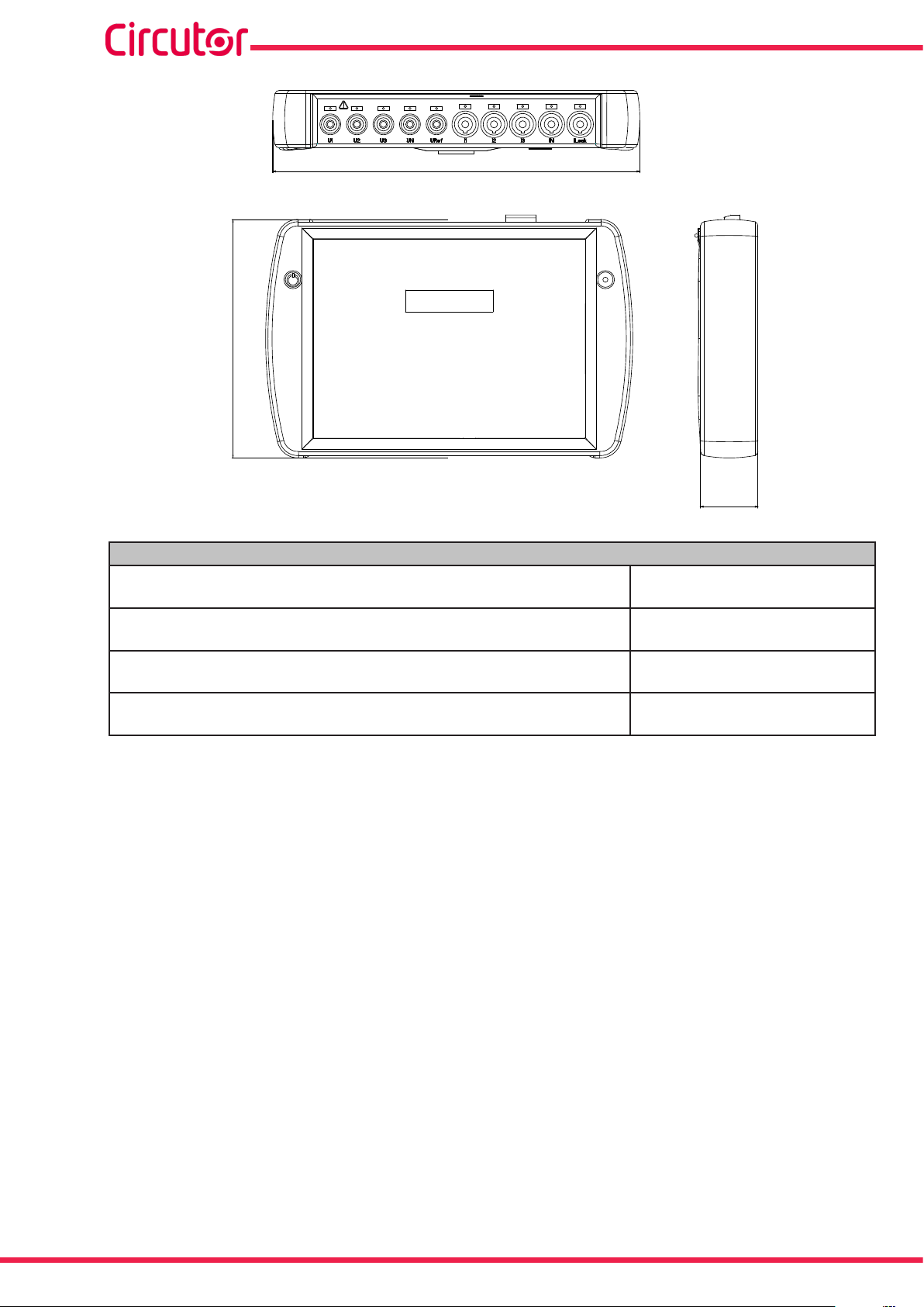
165.96
MYeBOX 150 - MYeBOX 1500
255.68
Figure 58: MYeBOX dimensions�
Standards
Electrical equipment for measurement, control and laboratory use EMC requirements - Part 1: General requirements
Electrical equipment for measurement, control, and laboratory use Part 1: General Requirements
Electrical equipment for measurement, control, and laboratory use Part 1: General Requirements
Safety requirements for electrical equipment for measurement, control, and laboratory use Part 1: General requirements
40
EN 61326-1:2013
UL 61010-1, 3rd Edition,
2012-05-11
CAN/CSA-C22.2 No. 61010-1-12,
3rd Edition, 2012-05
IEC 61010-1:2010, 3rd Edition
88
Instruction Manual
Page 89

MYeBOX 150 - MYeBOX 1500
guarantees its products against any manufacturing defect for two years after the
12�- MAINTENANCE AND TECHNICAL SERVICE
The device does not need any maintenance.
Only clean the screen with soapy water and dry with a soft dry cloth.
In the case of any query in relation to device operation or malfunction, please contact the
CIRCUTOR, SA Technical Support Service.
Technical Assistance Service
Vial Sant Jordi, s/n, 08232 - Viladecavalls (Barcelona)
Tel: 902 449 459 ( España) / +34 937 452 919 (outside of Spain)
email: sat@circutor.com
13�- GUARANTEE
CIRCUTOR
delivery of the units.
CIRCUTOR will repair or replace any defective factory product returned during the guarantee
period.
• No returns will be accepted and no unit will be repaired or replaced if it is not accompanied by a report indicating the defect detected or the reason for the return.
•The guarantee will be void if the units has been improperly used or the storage, installation and maintenance instructions listed in this manual have not been
followed. “Improper usage” is de ned as any operating or storage condition con-
trary to the national electrical code or that surpasses the limits indicated in the
technical and environmental features of this manual.
• CIRCUTOR accepts no liability due to the possible damage to the unit or other
parts of the installation, nor will it cover any possible sanctions derived from a possible failure, improper installation or “improper usage” of the unit. Consequently,
this guarantee does not apply to failures occurring in the following cases:
- Overvoltages and/or electrical disturbances in the supply;
- Water, if the product does not have the appropriate IP classi cation;
- Poor ventilation and/or excessive temperatures;
- Improper installation and/or lack of maintenance;
- Buyer repairs or modi cations without the manufacturer’s authorisation.
Instruction Manual
89
Page 90

14�- CE CERTIFICATE
MYeBOX 150 - MYeBOX 1500
90
Instruction Manual
Page 91

MYeBOX 150 - MYeBOX 1500
Instruction Manual
91
Page 92

MYeBOX 150 - MYeBOX 1500
92
Instruction Manual
Page 93

MYeBOX 150 - MYeBOX 1500
Instruction Manual
93
Page 94

CIRCUTOR, SA
Vial Sant Jordi, s/n
08232 -Viladecavalls (Barcelona)
Tel.: (+34) 93 745 29 00 - Fax: (+34) 93 745 29 14
www.circutor.com central@circutor.com
 Loading...