

Page 1

RELAY STATION
CBS-8 SERIES
INSTRUCTION MANUAL
( M98158101-20-06C-GB)
(c)
CIRCUTOR S.A.
Page 2

----- Relay Station CBS-8 -------- --- Page No. 1
CBS-8 ANALYZER INDEX Page No.
CHECKS ON RECEIPT..................................................................................................3
1.-
2.- GENERAL FEATURES ..................................................................................................4
3.- INSTALLATION AND START UP...................................................................................6
3.1.- Installing the equipment ....................................................................................6
3.2.- CBS-8 terminal ratios (as labels).......................................................................8
3.3.- CBS-8 connection diagram. ..............................................................................9
3.3.1.- For measuring current:................................................................................9
3.3.2.- For earth leakage protection: ....................................................................10
4.- OPERATION ................................................................................................................11
4.1.- Normal mode...................................................................................................12
4.2.- Test mode .......................................................................................................15
4.3.- Reset mode .....................................................................................................17
4.4.- Setting mode ...................................................................................................18
5.- SETTING(SET-UP menu) ............................................................................................19
5.1.- Channel setting ...............................................................................................19
5.1.1.- Setting common parameters.....................................................................20
5.1.2.- Channel setting: ........................................................................................21
5.1.2.1.- Selection of toroid connected. ............................................................21
5.1.2.2.- Earth leakage mode:...........................................................................22
5.1.2.3.- Reclosures..........................................................................................25
5.2.- Communication configuration..........................................................................27
5.2.- Time setting..................................................................................................... 29
6.- TECHNICAL FEATURES .............................................................................................30
7.- SAFETY ADVICE .........................................................................................................32
8.- MAINTENANCE ...........................................................................................................32
9.- TECHNICAL SERVICE ................................................................................................32
10.- CBS-8 COMMUNICATIONS... ..................................................................................33
10.1.- Please Note:.................................................................................................. 33
10.2.- RS-485 connection system to a PC (RS-232)...............................................34
10.3.- MODBUS© Protocol....................................................................................... 35
10.3.1.- Readout logs...........................................................................................36
Page 3

----- Relay Station CBS-8 -------- --- Page No. 2
10.3.2.- Operating logs.........................................................................................38
11.- APLICATION EXAMPLE ...........................................................................................39
Page 4
----- Relay Station CBS-8 -------- --- Page No. 3
1.- CHECKS ON RECEIPT
This manual assists in the installation and handling of the CBS-8 relay station to obtain
the best results from it. On receiving the equipment check the following:
a) The equipment is the same as the one you ordered.
b) Check that the equipment has not been damaged during delivery.
c) Check that it is supplied with the correct instruction manual.
d) CD with “EasyComm CBS-8” software
For safety reasons, it is vital that people installing or handling
the CBS-8 relay station follow the usual safety procedures as well
as the specific warnings contained in this instruction manual.
Check the following before connecting the equipment:
(a) Power supply voltage: see information on the side label.
Standard: 230 V AC. – Single phase, 50 ... 60 Hz
Other voltages: on request
(b) Maximum admissible current: according to toroid used (WG or WGP)
Page 5
----- Relay Station CBS-8 -------- --- Page No. 4
2.- GENERAL FEATURES
The CBS-8 relay station is programmable DIN rail mounted equipment offering
several operational options selected from menus on the equipment itself during set
up. Before starting the equipment carefully read the sections CONNECTION AND
SET UP and select the correct operating mode to obtain the required data.
Rd
Ed
S1S1S2 S2S2 S2S1S1
The CBS-8 is measuring equipment that calculates and displays the current
flowing in true effective values allowing decisions to be made on the operation to be
undertaken. It can operate as a maximum and minimum current relay and as earth
leakage protection. To do this, it has 8 input channels, 8 operating relay outputs (1
per channel), one alarm output and one test output.
Page 6

----- Relay Station CBS-8 -------- --- Page No. 5
Current is measured by calculating the true effective value of one cycle. If this
value exceeds a (preset) threshold for a time period set by the user, then the
corresponding operational relay is activated.
The behaviour of the relays can be selected depending on how the CBS-8 is
set up. They can act as blocking relays or with recoverable trip. In current relay
mode, selection is done via the keyboard and in earth leakage mode it is activated
via the “EasyComm CBS-8” software on the Cd supplied with the equipment.
The CBS-8 uses an LCD display to show the current or earth leakage and the
status of the operational relay for each of the 8 channels.
---------------------------------------------------------------------------------------------
OTHER FEATURES
- It is a small instrument to be mounted on a DIN rail.
- Measures in TRMS.
- Measurement in 8 independent channels.
- Channels configurable as earth leakage protectors or current relays.
- Alarm relay.
- Operation history logger.
- RS-485 communication for PC.
- Automatic resetting option (in RS-485 earth leakage channels).
- Pre-alarm registers (RS-485).
Page 7
----- Relay Station CBS-8 -------- --- Page No. 6
3.- INSTALLATION AND START UP
This manual contains information and warnings that the user
must follow to ensure the safe operation of the equipment and to keep
it in a safe condition. It must not be used until it is finally located on the
electrical board.
If this equipment is used in a way not specified by the
manufacturer, the equipment’s protection may be compromised.
If it is likely that safety has been affected (e.g. visible damage) the power
supply must be disconnected. In this event, contact a qualified service technician.
3.1.- Installing the equipment
Before running voltage through the equipment the following points must be
checked:
a.- Power supply voltage: see label on the side of the equipment.
- Standard power supply: Single phase 230 V ∼ (AC.)
Other voltages: on request
- Frequency : 50 - 60 Hz
- Power supply tolerance : + 15 % -20%
- Connection board : Terminals 1 - 28 (Power supply)
- Consumption : 4 W
Page 8
----- Relay Station CBS-8 -------- --- Page No. 7
b.- Maximum admissible current: According to the transformer used.
WGxx 30 mA - 3 A WGPxx 300 mA - 30 A
c.- Operating conditions:
- Operating temperature : -10 ºC to +50 ºC
- Relative humidity : 5 to 95 % HR (without condensation)
- Altitude : up to 2000 m
d.- Safety:
- Designed for category III installations - 300 V AC (EN 61010).
- Electric shock protection by class II double isolation.
Installation
:
The equipment is to be installed on 46277 DIN rail (EN 50022). All connections
are to be inside the electrical casing.
Remember that the terminals can be dangerous if touched when the equipment is
connected. Removing covers or parts may give access to parts that are dangerous if
touched. The equipment must not be used until it is completely installed.
The equipment must be connected to the power supply circuit with a minimum
1 mm2 cable and protected with gl (IEC 269) or M type fuse between 0.5 and 2 A. It
must be fitted with a short circuit breaking element or equivalent to disconnect it from
the power supply.
Page 9

----- Relay Station CBS-8 -------- --- Page No. 8
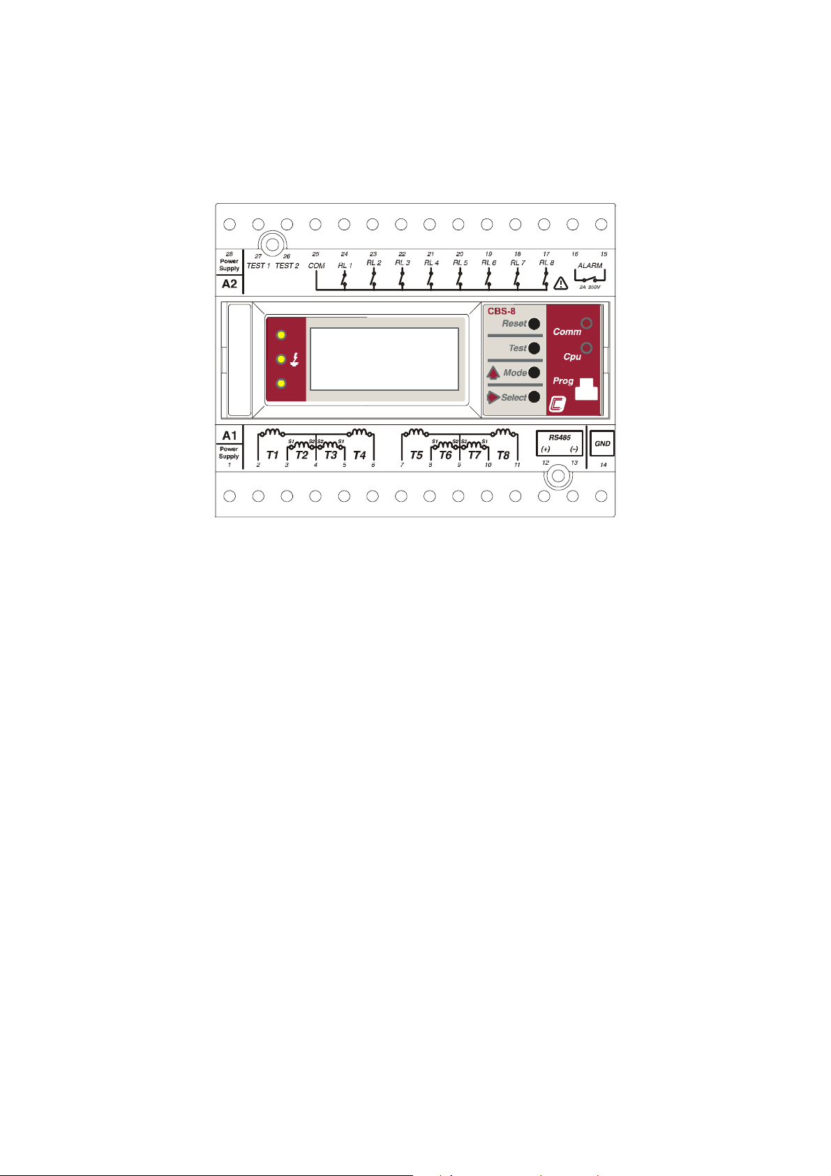
3.2.- CBS-8 terminal ratios (as labels)
Terminal No Name Type
1 - 28 Power Supply A1 - A2 Power supply 230 V AC.
27 – 26 Test 1 - Test 2 Test output
25 COM Common relay outputs
24 RL1 Relay output channel 1
23 RL2 Relay output channel 2
22 RL3 Relay output channel 3
21 RL4 Relay output channel 4
20 RL5 Relay output channel 5
19 RL6 Relay output channel 6
18 RL7 Relay output channel 7
17 RL8 Relay output channel 8
16 - 15 ALARM Alarm output
14
13
12
11 T8 – S1 S1 Current transformer channel 8
10 T7 –S1 S1 Current transformer channel 7
9 common – S2 S2 Current transformer channels 5,6,7 and 8
8 T6–S1 S1 Current transformer channel 6
7 T5–S1 S1 Current transformer channel 5
6 T4–S1 S1 Current transformer channel 4
5 T3–S1 S1 Current transformer channel 3
4 common-S2 S2 Current transformer channels 1,2,3 and 4
3 T2–S1 S1 Current transformer channel 2
2 T1–S1 S1 Current transformer channel 1
GND
( -- )
(+ )
COM CBS-8: RS-485 connection to PC.
14 GND ---------> 5 converter
13 -- ---------> 2 (--) RS-485/RS-232
12 + ---------> 1 (+)
NOTE: Current inputs are designed for WG or WGP transformers.
Page 10
----- Relay Station CBS-8 -------- --- Page No. 9
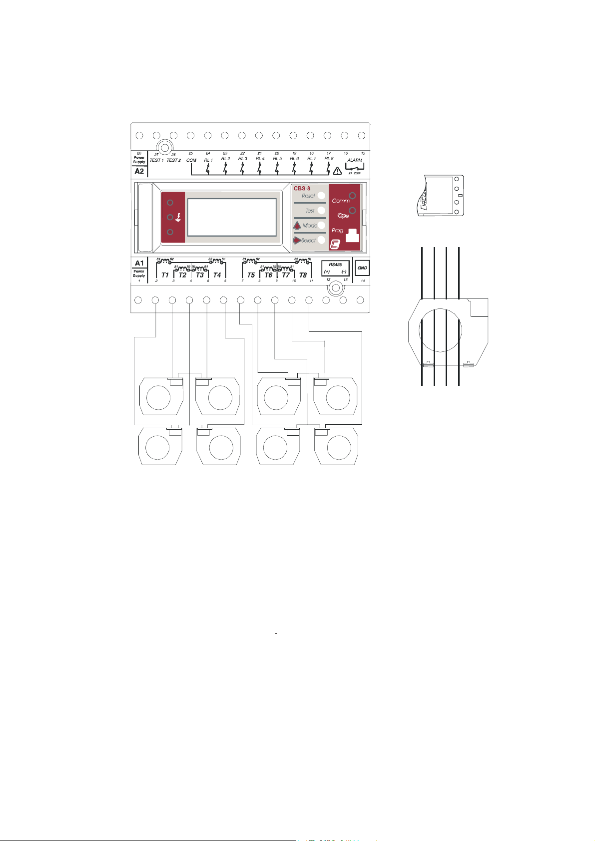
3.3.- CBS-8 connection diagram.
3.3.1.- For measuring current:
2S2
2S1
1S2
1S1
1S2
1S2
1S2
1S2
1S1
T7
1S1
T8
T2
T1
1S1
1S1
1S2
1S2
1S2
1S2
1S1
1S1
T3
T4
1S1
T6
1S1
T5
Page 11

----- Relay Station CBS-8 -------- --- Page No. 10
3.3.2.- For earth leakage protection:
CBS-8
Utilización 2
WG 2
Bobina 2
1S2
1S1
2S2
2S1
L1 L3L2 N
WG 1
Bobina 1
2S2
2S1
1S2
1S1
Rd
Ed
BOBINA-2
Utilización 1
Page 12

----- Relay Station CBS-8 -------- --- Page No. 11
-
4.- OPERATION
The equipment is designed for 50 Hz and 60 Hz installations.
This equipment may be used as for earth leakage measurement or for earth
leakage protection. This will depend on the connection (earth leakage protection) or
not (earth leakage current measurement) of the operational relay outputs for the
different channels.
The CBS-8 has several operating modes:
- Normal mode: The CBS-8 continuously measures currents. If the relay
outputs are connected it will be used for earth leakage protection or as a
current relay.
- Test mode: Checks the status of the connections between the CBS-8 and
toroidal as well as the working of the different LEDs.
- Reset mode: Allows the tripped channels to be reset.
- Set up mode: Allows the relay station to be configured.
The CBS-8 will always be in normal mode when it is switched
on.
It has 4 buttons and 5 LEDs that have a different following function according
to mode.
The CBS-8 has a non volatile, rotating memory where the 100 most recent
events are logged. Each log shows:
- Date
- Channel tripped
- Trip current
Page 13
----- Relay Station CBS-8 -------- --- Page No. 12
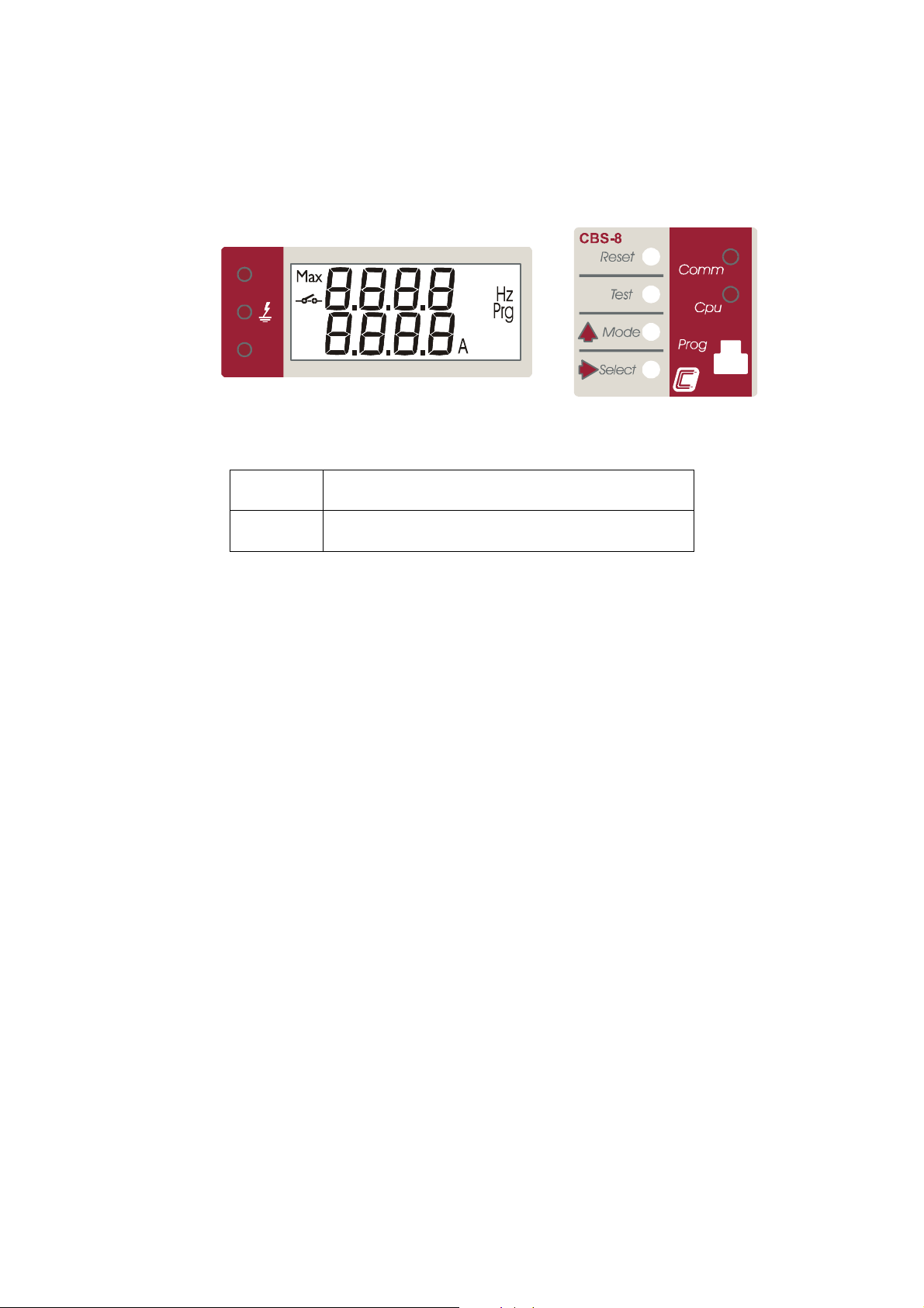
4.1.- Normal mode
The equipment has a 2 line LCD display:
Rd
Ed
When the CBS-8 is switched on the following information appears on the
display for a few moments:
CBS 8
xxxx
( Software version
After a few seconds the equipment is ready to be used and displays one of the
possible screens according to the set up.
NB: If the word “max” appears on the screen during normal operation, it
means that the detected current is higher than the preset range. In the event of this
happening the measurement will not be accurate.
Page 14

⇒ Buttons:
The 4 buttons perform the following operations in this operating mode:
- RESET button: Enters Reset mode. By pressing this button for 3 seconds,
the CBS-8 will enter the menu that will unblock one by one all blocked
relays. Also, if reclosures are activated the time and reclosure meters are
returned to zero.
- TEST button: Enters Test mode. By pressing this button for 3 seconds, the
CBS-8 will enter the menu that will self test the selected channel and check
the status of the output, the display LEDs, the electronics and the
connection between the toroid and the CBS-8.
----- Relay Station CBS-8 -------- --- Page No. 13
- MODE button:
Changes the display mode on the LCD. The selected
display mode will momentarily appear on the screen:
- UIS.1: Displays the earth leakage current for each channel and
the status of the associated relay.
- UIS.2: Displays the earth leakage current of the active channel.
- UIS.3: Indicates the status of each of the channels. The channel
status display screen will alternate, if the output is tripped, with
another that displays the threshold current of the trip and the
current that caused it to trip.
- UIS.4: Shows data for the most recent earth leakage current. The
display alternates between the channel number with the detected
earth leakage current and the date and time when it happened.
- UIS.5: Shows on one single screen the situation with all the
channels. 0 – On, 1 – tripped and P – Pre-alarm.
Page 15

----- Relay Station CBS-8 -------- --- Page No. 14
- SELECT button: According to the preset display mode, the function of this
button will be:
- UIS.2 or UIS.3 mode: Changes the channel displayed
- UIS.4 mode: Advances within history log.
- MODE and SELECT button: Enters set up mode. Depending on the switch
situation “PROG” will perform the following operations:
- Down: Enters set up allowing all configuration parameters to be
changed.
- Up (Blockable position): Enters set up mode, only allowing the
equipment’s configuration to be checked. It does not allow the
configuration of the equipment to be changed.
- RESET and SELECT button:
Allows the station to be up dated.
⇒ LEDs
The 5 LEDs on the CBS-8 display the following parameters:
- CPU LED: Always flashes when the equipment is working.
- COMM LED: Flashes when communication via the RS485 series channel is
established.
- Rd LED: Is lit when automatic reclosures are permitted.
- LED: Is lit when any channel has tripped. It will always flash when any
channel is in pre-alarm and there are no tripped channels.
- Ed LED: Is lit when any channel is blocked.
Page 16

----- Relay Station CBS-8 -------- --- Page No. 15
4.2.- Test mode
This is used to check the operation of toroid – CBS-8 connection, operational
relays, the equipment’s electronics and the LEDs.
The equipment does not check the line whilst it is
testing
Pressing the “TEST” button for three seconds will enter this mode when the
equipment is in normal operating mode.
The test is: injecting a current via the test terminals on the transformer. This
current is detected by the selected CBS-8 channel as an earth leakage, tripping it
operational relay.
The results of the test of the connection between transformer and the relay
station is shown by different messages on the screen:
) Channel to be tested
) Test result
goes into normal mode without reconnecting any blocked relay
Working correctly Working incorrectly
If no button is pressed for 30 seconds the equipment automatically
Page 17

----- Relay Station CBS-8 -------- --- Page No. 16
⇒ Buttons:
Once in Test mode the functions of the buttons will be:
- RESET button: Pressed when this mode is finished and prepares the CBS
for normal working.
- MODE button: Allows the selection of the channel to be tested.
- SELECT button: Starts the testing of the selected channel.
⇒ LEDs
The CBS-8 also checks the working of the LEDs. This test consists of all LEDs
being on for all the time it is in Test mode.
Rd
Ed
Page 18

----- Relay Station CBS-8 -------- --- Page No. 17
A
4.3.- Reset mode
This is used to reset those relays that have tripped.
The equipment checks the line whilst it is reset
This mode will be entered by pressing the “RESET” button for 3 seconds
when the equipment is in normal mode.
A menu will appear on the screen to select the channel which is to be reset.
mode
No tripped channels
Channel tripped
If no button is pressed for 30 seconds the equipment automatically goes into
normal mode without reconnecting any blocked relay
⇒ Buttons:
In Reset mode the functions of the buttons will be:
- RESET button: Ends RESET mode.
- MODE button: Allows the channel to be reset to be selected.
- SELECT button: Resets the selected channel.
All channel reset
LL
Page 19

----- Relay Station CBS-8 -------- --- Page No. 18
4.4.- Setting mode
This mode allows the relay station to be configured.
To enter this mode, press the MODE and SELECT keys at the same time in
normal mode.
Whilst the equipment is in setting mode it continues
checking the line with the parameters in use before entering
The earth leakage station has a protection system to prevent changes to the
configuration (“PROG” switch).
⇒ “PROG” switch
The working of this setting mode depends on the situation with this switch:
- Up (blockable position): the CBS-8 enters setting mode although
changing the channel configuration parameters is not permitted.
- Down: On entering setting mode all configuration parameters may be
changed.
setting
⇒ Buttons
When in setting mode:
- RESET button: Exits setting mode without making any changes.
- MODE button: Changes the selected menu option.
- SELECT button: Enters the selected option
- MODE and SELECT buttons: returns the equipment to normal
operating mode with the new configuration.
Page 20

----- Relay Station CBS-8 -------- --- Page No. 19
5.- SETTING(SET-UP menu)
Setting the CBS-8 is done via a series of SET UP menus.
) To access the setting menu the MODE and SELECT buttons are pressed at
the same time in normal mode (See section 4.4.)
Entering SET UP shows the screen to select the setting of the features of the
different channels or communications.
P.CHA Configuration of the different channels
C.SEr Configuration of the communications
The selected option will flash.
- MODE key moves forward the configurable options
- SELECT key enters the selected option.
- RESET Exits setting mode without making any changes.
- MODE and SELECT are used to enter the new setting and to move back
to normal operating mode.
5.1.- Channel setting
Once in SET-UP, by using the keyboard the different options may be selected
and the variables entered:
Where:
- P.CH - :shows common configurable parameters
- P.CH1 ... P.CH8: Configuration of each channel.
-
...
Page 21

----- Relay Station CBS-8 -------- --- Page No. 20
-
5.1.1.- Setting common parameters
The different options are now described in sequence:
1. Pre-alarm threshold.
2. Alarm contact status.
Pre-alarm threshold.
The minimum trip threshold of the channels set for earth leakage may be
changed between 50 and 80% in intervals of 10%
OFF – to disconnect the pre-alarm
MAIN – 100% trip treshold
Alarm relay output.
The type of relay is displayed. It may be selected from two possible values:
Page 22

----- Relay Station CBS-8 -------- --- Page No. 21
Normally open Normally closed
5.1.2.- Channel setting:
The following configuration is set for each of the 8 channels available to
the earth leakage station.
If the station is to be used only for earth leakage measurement it will
only be necessary to select the type of toroid that is connected to each
channel and the trip threshold.
5.1.2.1.- Selection of toroid connected.
It must be indicated if a toroid is used for each channel, if yes, then which
toroid is connected:
Not used WG 30 mA – 6,3A WGP 300 mA - 63A
Page 23

----- Relay Station CBS-8 -------- --- Page No. 22
5.1.2.2.- Earth leakage mode:
For equipment only used for earth leakage measurement, it will only be
necessary to set the trip threshold.
Trip threshold.
The current at which it will trip must be set (operating relay).
Channels used for earth leakage measurement must be set with the maximum
current to be measured. This value is very important because if an extremely high
value is set then accuracy will be lost and if a value lower than the measured current
is set, the input will be saturated and the measurement will be incorrect.
The value set must be one of those predefined values according to the toroid
used and the function mode:
Page 24

----- Relay Station CBS-8 -------- --- Page No. 23
30 mA ... 3A 300 mA ... 30A
30 mA 1 A 300 mA 10 A
50 mA 1,5 A 500 mA 15 A
100 Ma 2 A 1 A 20 A
200 mA 2,5 A 2 A 25 A
300 mA 3 A 3 A 30 A
400 mA 3,5 A 4 A 35 A
500 mA 4 A 5 A 40 A
600 mA 4,5 A 6 A 45 A
700 mA 5 A 7 A 50 A
800 mA 5,5 A 8 A 55 A
900 mA 6 A 9 A 60 A
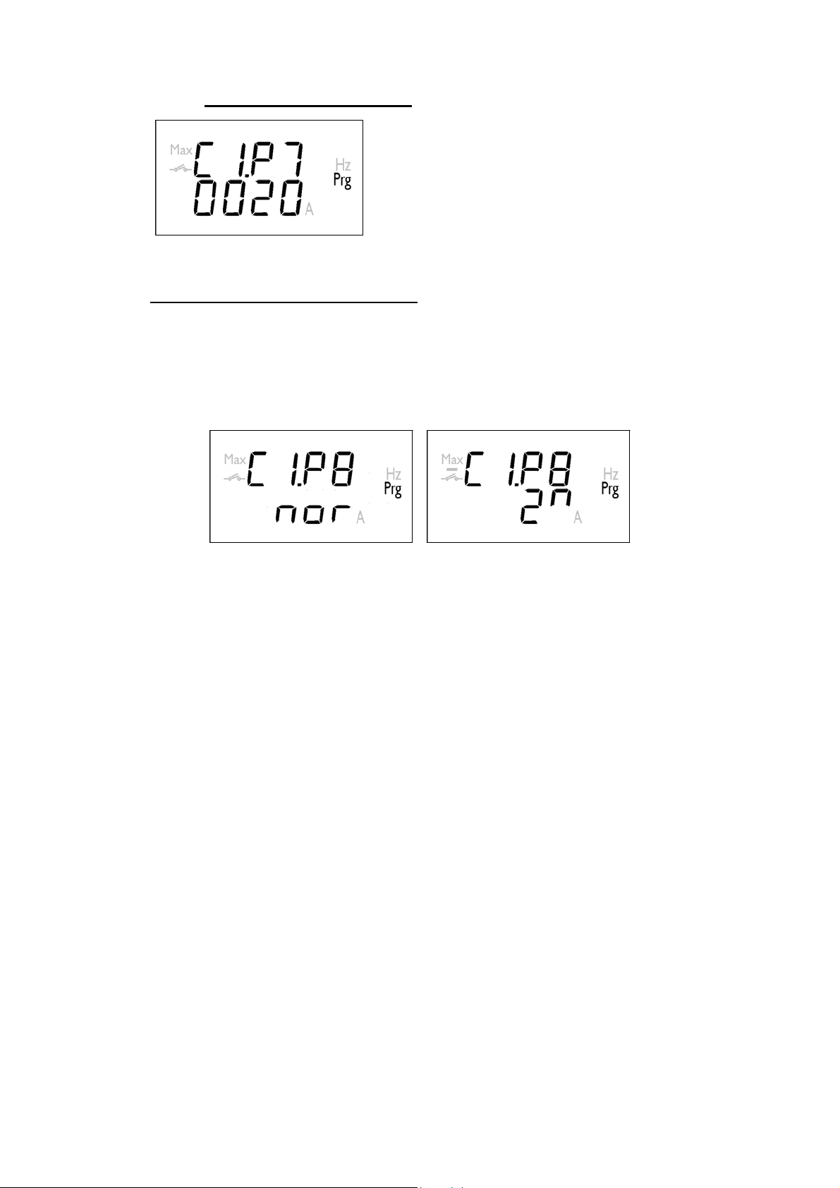
Delay time.
Time during which the earth leakage must exceed the trip threshold to activate
the operating relay for the corresponding channel.
Usual delay times on the equipment are:
INST. SEL. 0,10 sec. 0,40 sec. 0,80 sec.
1,0 sec. 3.0 sec. 5,0 sec. 10,0 sec.
Page 25

----- Relay Station CBS-8 -------- --- Page No. 24
Note: If the trip threshold is 30 mA , delay time wil be instantaneous.
Trip time for instantaneous trip position and selective trip position are:
In 0.2 seg. In 0.4 seg.
INST
1.5 In 0.15
seg.
2 In 0.02
seg.
SEL
1.5 In 0.3 seg.
2 In 0.12
seg.
Page 26

----- Relay Station CBS-8 -------- --- Page No. 25
Relay output type.
The required status of the relays when not operating must be specified. There
are two possible values:
normally open normally closed
5.1.2.3.- Reclosures
The options described below only appear if this option has been activated via
communication with the “EasyComm CBS-8” software
Active in all chanells Active in chanell 1
NOTE: It is recommended to activate the self-reclosing function if the device
controls an automatic switch for handling self-reclosing. Then it is not
necessary to reset the channel tripped in the CBS-8.
Page 27
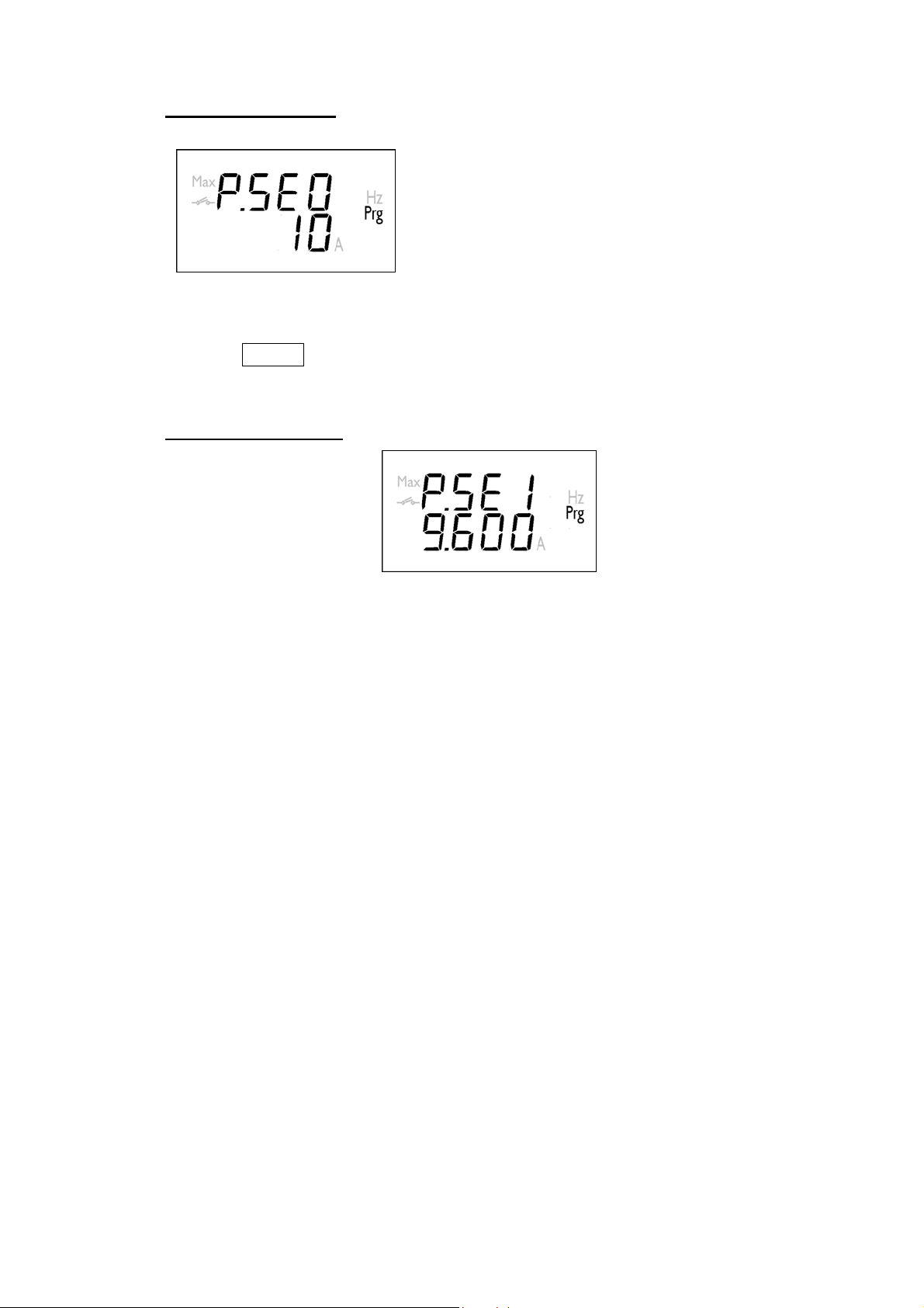
----- Relay Station CBS-8 -------- --- Page No. 26
Time between reclosures.
) Value between 1 and 900 seconds
Type of time between reclosures.
Applying time between reclosures creates two reclosure modes:
- Normal: Time between two consecutive reclosures is equal to the value preset
by the user in the previous parameter.
- Exponential: For each reclosure the reclosing time is: trec
n is the number of reclosures up to now and trec is the reclosing time selected
by the user.
= trec ·2n, where
n+1
Normal Exponential
Page 28

----- Relay Station CBS-8 -------- --- Page No. 27
Number of reclosures.
) Value between 0 and 10 reclosures.
If, after these attempts, reclosure has not been successful, the relay in
question remains blocked and has to be manually or remotely reset to unblock it.
Note:
Æ If the preset number of reclosures is 0, they remain deactivated.
Æ Reclosures are returned to zero when double the time between
reclosures has elapsed.
5.2.- Communication configuration
However if the selected option is C.SEr, this allows access to the menus to
change the communication series parameters.
The following screens will now appear:
Page 29
----- Relay Station CBS-8 -------- --- Page No. 28
Peripheral number:
The CBS-8 peripheral number on the MODBUS system.
) Peripheral No between 1 and 255.
Here the MODE key will perform the following functions:
- Short press: Increases the peripheral number 1 by 1:
- Long press: Increases the peripheral number 10 by 10.
Transmitting speed:
The permitted transmitting speeds are: 4800 – 9600 - 19200 bauds.
Page 30
----- Relay Station CBS-8 -------- --- Page No. 29
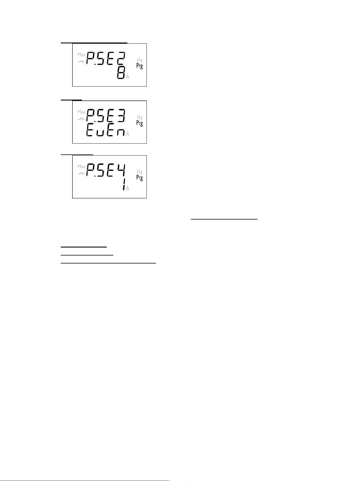
Number of data bits:
Parity:
Stop Bits:
) This value is always 8.
) No parity Æ none
Even Æ even
Odd Æ odd
) Stop Bits 1 or 2
5.2.- Time setting
To set the internal clock in the CBS-8 the RESET and SELECT buttons must
be pressed at the same time.
Then the date and time on the equipment may be changed using:
- MODE button: Advances the different menu options.
- SELECT button: Enters the selected option.
- RESET and SELECT buttons: Enters and ends the time configuration.
Page 31

----- Relay Station CBS-8 -------- --- Page No. 30
6.- TECHNICAL FEATURES
Power supply: see features on the back of the CBS-8
- CBS-8.... : Single phase: 230 V AC.
Voltage tolerance: -15 % / +20 %
Frequency : 50 - 60 Hz
Consumption ........................ 4 W
Operating temperature ......... –10º to 50 º C
Measurement circuit:
Current margin: According to toroidal transformer connected.
WGxx 30 mA – 6,3 A WGPxx 300 mA – 63 A
Type of measurement: True effective value
Sampling time: 1250µs
Pre-alarm:
Delay: 500 ms
Hysteresis: 50 %
Current accuracy: < 5%
Reclosures:
Nº reclosures: Programmable 0 ... 10
Time between reclosures: Programmable
Æ Normal Mode: 1 ... 900 seconds
Æ Exponential Mode: trec
Reset time: double the time between reclosures
Accuracy Class:
Current .............................. 5 %
Accuracy under measuring conditions:
- Current transformers not included.
- Temperature from + 5 ºC to + 45 ºC
= trec ·2n,
n+1
Page 32

----- Relay Station CBS-8 -------- --- Page No. 31
Mechanical features:
- Type of casing: Modular self extinguishing plastic.
- Connection: Metal terminals with "Pozidrive" screws
- Mounting: Symmetrical profile DIN 46277 (EN 50022) coupling.
Screw mounted option (Mounting hole ∅ 4.2 mm).
- Facing: Lexan front
- Protection Built in relay : IP 41
Terminals : IP 20
- Sizes: 140 x 70 x 110 mm (Relay 8 modules according to DIN 43 880)
- Weight: 0.560 kg
Output relay features :
- Maximum operating voltage : 250 V AC.
- Maximum operating current : 5 A
Safety .............. Category III - 300 V AC., EN-61010
Electric shock protection by double isolation class II
Standards: IEC 1008, IEC 1010, IEC 255-5, UNE 801-2, UNE 801-3, UNE 801-4,
UNE 60730-1, UNE 61010
Sizes:
45
140
110
70
Page 33

----- Relay Station CBS-8 -------- --- Page No. 32
7.- SAFETY ADVICE
Installation guidelines given in the previous sections
INSTALLATION AND START UP, TYPES OF INSTALLATION and
TECHNICAL FEATURES must be followed.
When the equipment is connected the terminals are dangerous
when touched and opening covers or removing parts may give access to parts that
are dangerous when touched. This equipment is supplied in good working order.
8.- MAINTENANCE
The CBS-8 does not require any special maintenance. Any adjustment,
maintenance or repair on open equipment must be avoided as far as possible. If this
is unavoidable it must be undertaken by someone qualified and informed of the
necessary procedure.
Before any change to the connections, replacement, maintenance or repair
the equipment must be disconnected from the power supply. If any operating or
protection fault with the equipment is suspected, it must be taken out of service,
ensuring against any accidental connection. The equipment is designed to allow
parts to be quickly replaced in the event of any breakdown.
9.- TECHNICAL SERVICE
In the event of any operating queries or equipment breakdown please
contact our Technical Service:
CIRCUTOR S.A. – After sales service
Vial Sant Jordi, s/n
08232 - Viladecavalls
Tel. – (+34) 93 745 29 00 & fax – (+34) 93 745 29 14
E-mail: central @ circutor.es
Page 34

----- Relay Station CBS-8 -------- --- Page No. 33
10.- CBS-8 COMMUNICATIONS...
16171819202122232425
1528
RL 5 RL 6
RL 8
RL 7
ALARM
2A 250V
RS485
GND
(+)
1312
14
1110987654321
----
2627
Power
RL 2
RL 1
COMTEST 2TEST 1
Supply
A2
Rd
Ed
S1 S1S2 S2S2S2S1 S1
A1
S1 S1S1 S1S2 S2S2S2
Power
Supply
T2 T6T3T7
T1 T5
T4T8
RL 3
RL 4
One or several CBS-8 instruments may be connected to a
computer. As well as the usual operation of each instrument this system can
centralise data at one single point. The CBS-8 has a 485 series communication
output. If more than one instrument is connected on one line each one has to be
assigned a number or address (from 01 to 255) so that the central computer sends
data requests to those addresses.
10.1.- Please Note:
- PROTOCOL: MODBUS © (Question/Answer)
- CBS-8 DEFAULT CONFIGURATION: 001/9.600 / 8 bits / N / 1 bit
- Possible speeds : 4.800 - 9.600 - 19.200 bauds
- RS-485 output: Terminal No. Signal
12 --------- TX +
13 --------- TX - 14 --------- GND
- The RS-485 is connected by a plaited insulated communications
cable, three wire minimum, with a maximum distance between PC and
final peripheral of 1,200 metres. The CBS-8 uses an RS-485
communication line that can be connected to a maximum of 32
instruments in parallel (multi-point Bus) for each used COM of the
computer.
Page 35

----- Relay Station CBS-8 -------- --- Page No. 34
10.2.- RS-485 connection system to a PC (RS-232)
RS-232
A1
RS-485
7
512
5
5
32
A2
CONVERTER
RS-232 / RS-485
5
2
1
CBS-8
DB-9
7
3
2
PC
CBS-8
12
13
14
*If the RS485/232 converter with RTS control is used (code 770208), it is not necessary
to use the 7 pin connection on the RS-232.
Page 36

----- Relay Station CBS-8 -------- --- Page No. 35
10.3.- MODBUS© Protocol
The CBS-8 system analyzer can communicate via MODBUS©
protocol, as described below.
The MODBUS© protocol uses RTU mode (Remote terminal Unit). Each
8-bit byte in a message contains two hexadecimal 4 bit characters.
The format for each byte in RTU mode is:
* Code : 8- bit binary , hexadecimal 0-9, A-F
2 hexadecimal characters in each 8
bit field of the message.
* Bits per byte : 8 data bits
* Field CHECK- ERROR : CRC (Cyclical Redundancy Check).
MODBUS FUNCTIONS USED IN THE CBS-8
:
FUNCTION 03h and 04h Reading n Words (16 bits - 2 bytes). The reading
function used by all of the CBS-8 parameters.
FUNCTION 06h Writing one WORD (16 bits - 2 bytes) in one
position in the memory.
FUNCTION 10h Writing n WORDS (16 bits - 2 bytes) in
consecutive positions in the memory.
Page 37

----- Relay Station CBS-8 -------- --- Page No. 36
10.3.1.- Readout logs
To read these logs the Modbus 03H or 04H function is used.
Two types of data can be distinguished in the equipment’s memory:
- Variables: Corresponding to all information supplied by the CBS-8
on the measurements made and the status of the relays.
- Logs (Histories): These logs store the last 100 operations done by
the station.
Variables
Description Units
Date* 0000-0001
Earth leakage
current
Output status
Alarm relay status
Trip current (mA) 0013 0014 0015 0016 0017 0018 0019 001A
Last recorded trip 001B
Operating mode 001C
“PROG” switch
Software Version 001E
Pre-alarm activated
(mA) 0002 0003 004 0005 0006 0007 0008 0009
0=Not tripped
1=Exceeded.
2=Tripped.
3=Blocked.
0=Not activated
1=Activated
0 = Up
1 = Down
0=Not activated
1=Activated
000A 000B 000C 000D 000E 000F 0010 0011
001F 0020 0021 0022 0023 0024 0025 0026
MODBUS LOGS HEXA-DECIMAL (longs)
Channel
1 2 3 4 5 6 7 8
0012
001D
Date Format:
b0 - b5 Seconds b17 - b21 Day of the month
b6 - b11 Minutes b22 - b25 Month
b12 - b16 Hour b26 - b31 Year + 2000
Page 38

----- Relay Station CBS-8 -------- --- Page No. 37
Memory log (History)
Trips are recorded in the equipment’s memory. The structure of this data in the
memory is in 4 recording blocks.
The table shows the starting log and the final reading
Event 0 1 2 3 4 5 6 7 8 9
00 0400 0404 0408 040C 0410 0414 0418 041C 0420 0424
10 0428 042C 0430 0434 0438 043C 0440 0444 0448 044C
20 0450 0454 0458 045C 0460 0464 0468 046C 0470 0474
30 0478 047C 0480 0484 0488 048C 0490 0494 0498 049C
40 04A0 04A4 04A8 04AC 04B0 04B4 04B8 04BC 04C0 04C4
50 04C8 04CC 04D0 04D4 04D8 04DC 04E0 04E4 04E8 04EC
60 04F0 04F4 04F8 04FC 0500 0504 0508 050C 0510 0514
70 0518 051C 0520 0524 0528 052C 0530 0534 0538 053C
80 0540 0544 0548 054C 0550 0554 0558 055C 0560 0564
90 0568 056C 0570 0574 0578 057C 0580 0584 0588 058C
The recorded event format (8 bytes) will be:
1 byte
2 byte
3 byte
Operation date
4 byte
5 byte
6 byte
Trip current
7 byte Trip channel
8 byte Not used
Page 39

----- Relay Station CBS-8 -------- --- Page No. 38
10.3.2.- Operating logs
There are a series of configuration operations that can only be done through
communications:
These variables are used with the log writing function.
Channel RESET
Writing
NP06030XFFFFCRC
Response
NP06030XFFFFCRC
Where x is the channel number (1-8) to Reset (0-All channels)
Deleting the operation file
Writing
NP06030EFFFFCRC
Response
NP06030EFFFFCRC
Page 40

----- Relay Station CBS-8 -------- --- Page No. 39
11.- APLICATION EXAMPLE
In this example, the leakage trip is produced feeding the switchgear tripping
coils through the CBS-8 outputs.
Page 41

----- Relay Station CBS-8 -------- --- Page No. 40
Switchgear tripping coils
 Loading...