

Page 1

Conversor / Amplificador CAMO
M54090 - CAMO
CONVERSOR-AMPLIFICADOR
MULTISERIE OPTOACOPLADO
1.- Características
CAMO es un convertidor de protocolo que
permite la comunicación entre un puerto de
comunicaciones RS-232 estándar y hasta 32
equipos mediante bus RS-485 ó 10 equipos RS-
422. Puede realizar también la función de
amplificador-repetidor de señales de bus RS485, permitiendo una mayor longitud de
cableado entre el maestro y los diferentes
periféricos. El equipo trabaja como convertidor
o amplificador de forma automática, en función
de las tramas que detecta.
2.- Consideraciones
Para la instalación o manipulación del
equipo, siga las instrucciones del
fabricante, de lo contrario su seguridad
Recuerde desconectar la alimentación del equipo
antes de manipular la unidad.
Con el equipo conectado, los bornes pueden ser
peligrosos al tacto, y la apertura de cubiertas ó
eliminación de elementos puede dar acceso a
partes peligrosas al tacto. El equipo no debe ser
alimentado hasta que haya finalizado por completo
su instalación.
El equipo debe conectarse a un circuito de
alimentación protegido con fusibles tipo gl.
(IEC 269) ó tipo M, comprendido entre 0.5 y 2 A.
Deberá estar previsto de un interruptor magnetotérmico o dispositivo equivalente para desconectar
el equipo de la red de alimentación. El circuito de
alimentación se conectará con cable de sección
mínima 1 mm².
puede resultar comprometida.
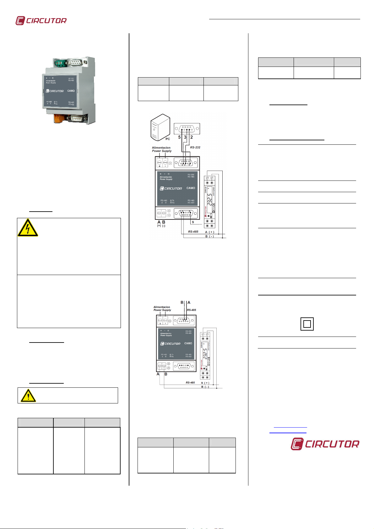
El conector DB9 hembra del dispositivo
(situado en la parte alimentación auxiliar) utiliza
los pines 2, 3 y 5 para la entrada RS-232 (ver
tabla 1).
El conexionado del bus RS-485 de salida,
puede realizarse por el conector DB9 (ver tabla
2), o desde los conectores A-B situados al lado
de los leds indicadores de
transmisión/recepción.
DB-9 macho Protocolo Función
1
2
5
RS-485
RS-485
RS-485
Tabla 2
A
B
GND
Figura 1
4.2.- Amplificador RS-485 a RS 485
Para usar el equipo como amplificador, debe
conectar la entrada del bus RS-485 mediante
los conectores 5, 8 y 9 (ver tabla 1).
La salida amplificada RS-485 mediante el DB9
se conecta como se indica en la tabla 2 o
como se muestra en la figura 1. La salida
mediante los bornes A-B se muestra en la
figura 2.
El equipo dispone de 2 LED de color rojo,
indicadores del estado de las comunicaciones
serie (ver tabla 4)
Posición Protocolo Función
Superior
Inferior
RS-422 ó 485
RS-422 ó 485
Tabla 4
TX
RX
5.- Mantenimiento
Este equipo no requiere de mantenimiento
específico. Debe asegurarse de que el equipo
se encuentra desconectado entes de
manipularlo.
6.- Características técnicas.
Alimentación:
- Alimentación fuente conmutada:
CA: 90…260Vca. 50…60 Hz
CC: 100…300Vcc.
- Alimentación Vcc:
CC: 10…36Vcc
- Consumo: 2 VA (90V) / 3 VA (260V)
- Temperatura trabajo: 0...50ºC
- Humedad (sin condensación) 5..95%
- Altitud: 2000m
Comunicación:
- Velocidad de transmisión (entre 600 y
57.600 bps), longitud de palabra y
conmutación Rx / Tx automáticas.
Características mecánicas:
- Tipo caja: Modular.
Plástico auto extinguible.
- Fijación: Acoplable perfil simétrico
- Dimensiones : 53 x 90 x 58 mm
- Peso : 0,091 kg
Visualizador:
Tipo : LED
- Seguridad: CAT III – 300 V c.a.
- Protección al choque eléctrico:
DIN 46277 (EN-50022)
(3 módulos – DIN 43 880)
RX, TX y POWER (Alimentación)
(EN-61010)
doble aislamiento clase II
3.- Instalación
La instalación del equipo se realiza sobre carril
DIN, quedando todas las conexiones en el
interior de un cuadro eléctrico. El equipo
dispone de un led indicador de alimentación que
indica su estado, al lado del conector de
alimentación auxiliar.
4.- Conexionado
Utilizar únicamente los pines indicados
para cada uno de los conexionados.
Usar más pines de los indicados puede
provocar un mal funcionamiento.
4.1.- Conversor RS-232 a RS 485
DB-9 hembra Protocolo Función
1
2
3
4
5
6
7
8
9
RS-232
RS-232
-
RS 232/485
-
-
RS-485
RS-485
Tabla 1
RX
TX
-
GND
-
-
B
A
Figura 2
4.3.- Salida RS 422
En caso de conectar equipos en RS-422 debe
seguir las indicaciones de la tabla 3, usando
los pines 5, 6, 7, 8 y 9.
DB-9 macho Protocolo Función
5
6
7
8
9
RS-422
RS-422
RS-422
RS-422
RS-422
Tabla 3
GND
TX +
TX RX RX +
- IP 20
Normas :
EN-61000-6-2, EN-61010
7.- Servicio Técnico
En caso de cualquier duda de funcionamiento o
posible avería del equipo, póngase en contacto
con nuestro servicio técnico.
Vial Sant Jordi, s/n
08232 Viladecavalls
(Barcelona) Spain
Tel. 902 449 459 (España)
Tel. (+34) 93 745 29 00 (Fuera de España)
Fax (+34) 93 745 29 14
e-mail: sat@circutor.es
web: www.circutor.es
M98237901-20-12C
Page 2
M54090 - CAMO
OPTOISOLATED MULTISERIE
AMPLIFIER CONVERTER
Converter / Amplifier CAMO
DB9 female connector (located in the supply
side) uses pins 2, 3 and 5 for RS-232 input
(see table 1).
The RS-485 output connection is possible to do
from the DB9 connector (see table 2) or from
the A-B connectors located beside of the
transmission/reception communications LED.
DB-9 male Protocol Function
1
2
5
RS-485
RS-485
RS-485
Table 2
The device has two red LED to inform the
serials communications status (see table 4).
Position Protocol Function
A
B
GND
Up
Down
5.- Maintenance
RS-422 or 485
RS-422 or 485
Table 4
TX
RX
This device does not require specific
maintenance. You must ensure that the device
is disconnected before operation.
1.- Features
CAMO is a protocol converter that allows the
communications between RS-232 master and
until 32 peripherals in RS-485 or till 10 devices
in RS-422. Allows to amplifier the
communications signal in RS-485 bus to reach
more length of wiring between the master and
the different peripherals. The function of
converter or amplifier is automatically done by
the device by the communications frames
detected.
2.- Caution
Before making any maintenance
operation, connection modification,
repair, etc., you must disconnect the
device from all power supplies. If you
suspect an operational fault in the unit or in its
protection system, remove the unit from service.
Note that when the instrument is switched on, the
terminals may be dangerous when touched an
opening or removing parts may access dangerous
areas. Therefore, the equipment must not be used
until it is properly installed.
The equipment must be connected to a power
supply circuit protected with gl (IEC 269) or type M
fuses between 0.5 and 2 A. It must have an
overload/short circuit switch or equivalent device in
order to disconnect the equipment from the power
supply system. An earth leakage switch or similar
device must be fitted to disconnect the equipment
from the power supply system. The power supply
circuit are connected with a cable with a minimum
diameter of 1 mm².
3.- Installation
Installation of equipment is done on a DIN rail,
leaving all the connections inside an electrical
panel. The unit has a supply LED indicator next
to the power connector that indicates its status.
4.- Connection
Use only the pins indicated for each
wiring. Use more pins than listed will
cause device malfunction.
4.1.- RS-232 to RS 485 converter
DB-9 female Protocol Function
1
2
3
4
5
6
7
8
9
RS-232
RS-232
-
RS-232/485
-
-
RS-485
RS-485
Table 1
RX
TX
-
GND
-
-
B
A
Picture 1
4.2.- RS-485 to RS 485 Amplifier
To use as amplifier you have to connect the
input in pins 5, 8 and 9 (see table 1).
The amplified RS-485 output can be wired from
DB9 as indicates the table 2 (see picture 1).
The RS-485 output through terminals A-B is
like indicates picture 2.
Picture 2
4.3.- RS 422 output
In RS-422 output is necessary to follow the
connections in the table below with pins 5, 6, 7,
8 and 9.
DB-9 male Protocol Function
5
6
7
8
9
RS-422
RS-422
RS-422
RS-422
RS-422
Table 3
GND
TX +
TX RX RX +
6.- Technical features
Supply:
- Switched power supply:
AC: 90…260Vac 50…60 Hz
DC: 100…300Vcc.
- Vcc supply:
CC: 10…36 Vcc
- Consumption 2 VA (90V) / 3 VA (260V)
- Working temperature 0..50ºC
- Humidity (non condensing) 5..95%
- Altitude 2000m
Communication:
Baudrate from 600 to 57.600, word size and
Rx/Tx conmutation auto-configured
Mechanical features:
- Box type: Modular.
V0 Plastic self-extinguishing.
- Fixation: Coupled symmetric profile
DIN 46277 (EN-50022)
- Size : 53 x 90 x 58 mm
(2 Din rail modules– DIN 43 880)
- Weigh : 0,091 kg
Visualization:
Type : Rx, Tx and POWER LED
- Safely CAT III – 300 V c.a.
(EN-61010)
- Protection against electric shock:
double isolation class II
- IP 20
Standards :
EN-61000-6-2, EN-61010
7.- TECHNICAL SERVICE
For any inquiry about the instrument
performance or whether any failure happens,
contact to technical service:
Vial Sant Jordi, s/n
08232 Viladecavalls
(Barcelona) Spain
Tel. 902 449 459 (Spain)
Tel. (+34) 93 745 29 00 (Out of Spain)
Fax (+34) 93 745 29 14
e-mail: sat@circutor.es
web: www.circutor.com
M98237901-20-12C
 Loading...