

Page 1

SUPPLY NETWORK ANALYZER
AR5 and AR5-L
INSTRUCTION MANUAL
( M98151101-03-10B )
(c)
CIRCUTOR S.A.
Page 2

CONTENTS page
1.- BASIC INSTRUCTIONS ........................................................................ 4
1.1.- Introduction: check the contents of your package................................. 4
1.2.- Safety conditions................................................................................... 4
1.3.- Connection instructions......................................................................... 4
1.4.- Operation instructions ........................................................................... 5
2.- ANALYZER MAIN FEATURES.............................................................. 6
2.1.- Basic features ....................................................................................... 6
2.2.- Other characteristics ............................................................................. 6
3.- KEYBOARD FUNCTIONS..................................................................... 9
4.- Installation AND START-UP .................................................................. 9
4.1.- Steps necessary for the START-UP ..................................................... 9
4.2.- Connection diagram............................................................................ 11
4.3.- Starting the analyzer up ...................................................................... 16
4.4.- Loading a new program ...................................................................... 18
4.5.- Turn the analyzer off ........................................................................... 19
4.6.- Back-light ............................................................................................ 19
4.7.- Choice of the working program ........................................................... 19
4.8.- Recharging the analyzer battery ......................................................... 20
4.9.- Energy saving ..................................................................................... 20
5.- DATA VISUALIZATION ON DISPLAY................................................. 21
5.1.- Base screen........................................................................................ 21
5.1.1.- Screen of instantaneous values.................................................... 21
5.1.2.- Screen of maximum and minimum values ................................... 22
5.2.- Other visualization screens................................................................. 23
5.2.1.- Visualization of 3 parameters in a big size mode.......................... 23
5.2.2.- Bar graphs .................................................................................... 24
5.2.3.- Oscilloscope.................................................................................. 25
5.2.3.1.- Three phases: Voltage - Current............................................. 25
5.2.3.2.- Zoom....................................................................................... 26
5.2.3.3.- Harmonic factorization. ........................................................... 27
5.2.4.- Setup visualization ........................................................................ 29
5.3.- Warning messages ............................................................................. 29
6.- PROGRAMMING THE ANALYZER..................................................... 30
2
Page 3

6.1.- SETUP menu...................................................................................... 31
6.1.1.- MEASURE .................................................................................... 32
6.1.1.1.- WIRING: Circuit type............................................................... 32
6.1.1.2.- PT/CT : Transformation ratios................................................. 32
6.1.2.- RECORD menu ............................................................................ 32
6.1.2.1.- PERIOD: recording period ...................................................... 33
6.1.2.2.- TRIGGER: Trigger conditions ................................................. 34
6.1.2.3.- NAME: recording file name ..................................................... 37
6.1.2.4.- PARAM: Choosing the parameters to be saved...................... 38
6.1.3.- COMM: Communication parameters............................................. 39
6.1.4.- CLOCK: Internal clock .................................................................. 39
6.1.5.- PASSWORD: Safety setting. ........................................................ 40
6.1.6.- RECALL: Read configuration........................................................ 41
6.2.- DISPLAY menu................................................................................... 42
6.2.1.- BAR.GR. ....................................................................................... 42
6.2.2.- EXPAND ....................................................................................... 42
6.2.3.- CONTRAST: Screen contrast ....................................................... 42
6.2.4.- ANGLE.......................................................................................... 43
6.3.- RUN: data recording process status ................................................... 43
6.4.- FILES Menu........................................................................................ 43
6.4.1.- DIR: Directory ............................................................................... 43
6.4.2.- DELETE: Deleting a file ................................................................ 43
6.4.3.- FORMAT: Formatting the analyzer internal memory..................... 44
6.5.- CLEAR menu: Deleting data............................................................... 44
6.6.- Menu OFF: Enable / Disable Password. ............................................. 45
6.7.- Menu LANGUAGE .............................................................................. 45
7.- ANALYZER COMMUNICATIONS ....................................................... 45
8.- TECHNICAL SPECIFICATIONS.......................................................... 46
9.- SAFETY WARNINGS .......................................................................... 48
10.- MAINTENANCE................................................................................... 49
11.- CHANGING THE BATTERY................................................................ 49
12.- TECHNICAL SERVICE........................................................................ 50
3
Page 4

1.- BASIC INSTRUCTIONS
This manual is aimed to familiarize de user with the operation of the portable
power analyzers model AR5-L and AR5 in order to get the best from its features.
These analyzers have been built with components incorporating the most
advanced technology in microelectronics and offer benchtop features over the market
in measurement and recording of electrical magnitudes in industrial power supply
networks.
You are kindly requested to carefully read this manual before connecting
and powering the analyzer in order to avoid irreversible damage, which might be
caused by an improper connection.
1.1.- Introduction: check the contents of your package
After receiving the analyzer, please check the following points:
a) The analyzer model corresponds with your order specifications.
b) After unpacking, check that the instrument has not been damaged in transit
c) The standard set includes the following items:
• Kit AR5-L or AR5
• 1 Power supplier set 100 V a.c. – 240 V a.c. / 12 V d.c.
• 1 Connection cord between the power supplier set and the main.
• 1 Connection cable between the analyzer and the power supplier
set.
• 1 RS-232 communication cable.
• 4 Voltage leads.
• 4 Alligator clamps (3 in AR5 model).
• 1 Instruction Manual.
• CD with the PC program
1.2.- Safety conditions
The manual you hold in your hands contains information and
warnings about the analyzer that the user should respect in order to
guarantee a proper operation of all the instrument functions and keep
its safety conditions.
1.3.- Connection instructions
.
Before powering and connecting the analyzer check the following points:
a) Supply voltage: Through and external power supplier set.
Input mains 100 V a.c. – 240 V a.c. / output to AR5/AR5-L 12V d.c.
b) Frequency : 45...65 Hz.
c) Maximum voltage at the voltage measuring circuit:
500 V a.c. Phase-to-neutral (CAT III)
4
Page 5
d) Current measuring range: according to the Current clamp used
Current clamps Measuring range
CP-2000-200
10 to 2000 A a.c. (switch at 2000)
1 to 200 A a.c. (switch at 200)
CPR-1000 5 to 1000 A a.c.
CPR-500 2,5 to 500 A a.c.
CP-100 (M1-U) 0, 5 to 100 A a.c.
CP-5
25 mA to 5 A a.c.
Flexible clamp Measuring range
C-FLEX 200-2000-20000 100 to 20000 A a.c (scale 20000
A)
10 to 2000 A a.c. (scale 2000 A)
1 to 200 A a.c. (scale 200 A)
NOTE: It is advisable to measure near of full-scale value to get better accuracy.
1.4.- Operation instructions
The analyzer is a programmable instrument so offering diverse operation
modes, which can be selected from the available programming menus (6.PROGRAMMING THE ANALYZER).
Please read carefully the paragraphs involving (4.- Installation AND STARTUP 6.- PROGRAMMING THE ANALYZER) in order to select the most suitable
operation mode for your requirements.
If the instrument is not used according to
manufacturer’s specifications, the protection of
the instrument can be damaged.
5
Page 6
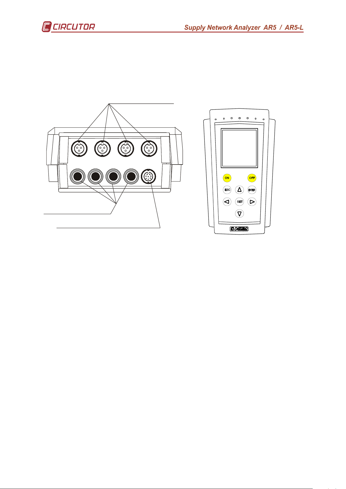
2.- ANALYZER MAIN FEATURES
Clamp inputs (.. 2 V a.c.).
Power Supply: 12 V c.c. / Serial input
VL1
VL2
VL3
AUX
*
*
2.1.- Basic features
The AR5 series analyzers are programmable instruments that measure,
calculate and store to memory the main parameters of three phase electrical
supply networks.
a.c. Voltage inputs
IL2IL3
IL1 I
N
N
* IN only in AR5-L models
Setup: Analyzer’s setting is completed through a system of spreadable menus
that provide a friendly-use and intuitive configuration process.
Data visualization: By means of a liquid crystal graphical display, 160 x 160
pixels and with backlight ability, the user can view instantaneous, maximum and
minimum values of each parameter at each phase.
Internal battery: permits the user to accomplish with analysis works without
the need of an external auxiliary power supply. The analyzer is equipped with an
intelligent battery charging system, which expands the battery life span. For recharge
the battery is necessary to connect the power supplier.
Installation: Analyzer is suitable for analysis works over any type of electric
networks (single-phase, bi-phase, 3-wire and 4-wire).
Measuring: Measurement of average values of main electrical parameters, as
well as, recording of maximum and minimum values. To execute these
measurements, the analyzer is equipped with three a.c. voltage inputs and four a.c.
current inputs (through current clamps ../ 2 V a.c.).
Data collection: The analyzer has a 1 Mb on-board memory to save into all
the parameters measured or calculated by the analyzer, in order to be further
retrieved from a PC.
PC software: together with the analyzer, it is also factory supplied a friendlyuse, powerful software that permits data downloading from the internal memory to a
PC and a further complex analysis of recorded data.
2.2.- Other characteristics
6
Page 7
- Small size, low weight, portable instrument.
- True R.M.S. measuring system.
- Instantaneous, maximum and minimum values of each discrete electric
parameter.
- Electrical energy meters incorporated
- Harmonic measurement
- Neutral current measurement (only in AR5-L model)
- RS-232 communication to PC
- Ability of setting a recording threshold, so that data is only recorded in
memory when measured values are not within the defined threshold (see
Section 6.1.2.2.-TRIGGER: Trigger conditions).
- Automatic data collection in memory at regular user-definable periods.
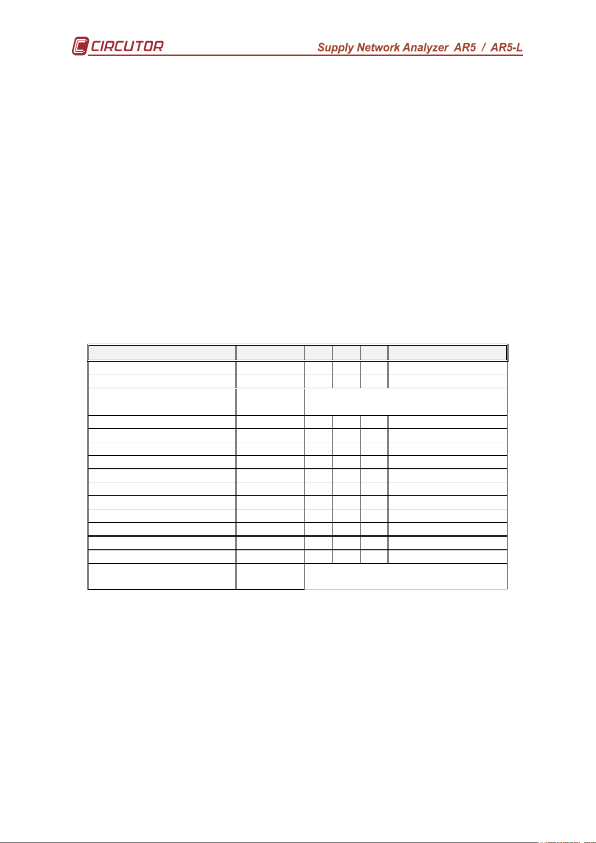
Depending on the type of circuit under analysis, following enumerated
parameters are measured and can be saved in memory:
NOTE: It’s not allow to save cosϕ data in memory. Only can be read on
display.
• 4-wire three-phase system:
Parameter Symbol L1 L2 L3 Three-phase value
Phase-to-Neutral voltage V x x x
Current A x x x x
Neutral current
(only in AR5-L model)
Frequency Hz x
Active power kW x x x x
Reactive power L kvarL x x x x
Reactive power C kvarC x x x x
Apparent power kVA x
Power factor PF x x x x
Active energy
Reactive-energy (inductive)
Reactive-energy (capacitive)
Voltage harmonics x x x
Current harmonics x x x
Current Neutral harmonics
(only in AR5-L model)
IN x
kW h
kvaLh
kvaCh
x
x x x x
x x x x
x x x x
7
Page 8
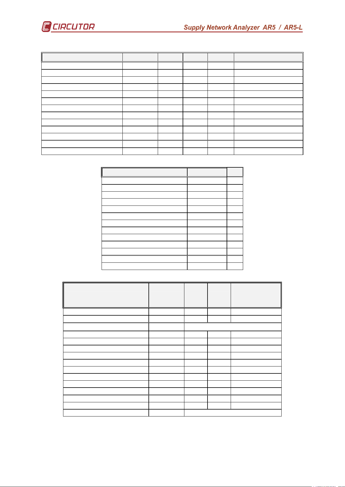
• 3-wire three-phase system:
Parameter Symbol L1-L2 L2-L3 L3-L1 Three-phase value
Phase-to-Phase voltage
Current
Frequency
Active power
Reactive power L
Reactive power C
Apparent power
Power factor
Active energy
Reactive-energy (inductive)
Reactive-energy (capacitive)
Voltage harmonics
Current harmonics
V
A
Hz
kW
kvarL
kvarC
PF
kW h
kvahL
kvahC
• Single-phase system:
Parameter Symbol L1
Voltage
Current
Frequency
Active power
Reactive power L
Reactive power C
Apparent power
Power factor
Active energy
Reactive-energy (inductive)
Reactive-energy (capacitive)
Voltage harmonics
Current harmonics
x x x
x x x x
x
x x x x
x x x x
x x x x
x
x x x x
x x x x
x x x x
x x x x
x x x
x x x
V
A
Hz
kW
kvarL
kvarL /(-C)
PF
kW h
kvahL
kvahC
x
x
x
x
x
x
x
x
x
x
x
x
x
• Bi-phase system:
Parameter Symbol L1-N
Voltage
Current
Neutral current*
Frequency
Active power
Reactive power L
Reactive power C
Apparent power
Power factor
Active energy
Reactive-energy (inductive)
Reactive-energy (capacitive)
Voltage harmonics
Current harmonics
Neutral current harmonics
*only in AR5-L model
L2-N
Bi-phase
value
L1-L2
V
A
IN
Hz
kW
kvarL
kvarC
PF
kW h
kvahL
kvahC
x x x
x x x
x
x
x x x
x x x
x x x
x
x x x
x
x x x
x x x
x x
x x
x
8
Page 9
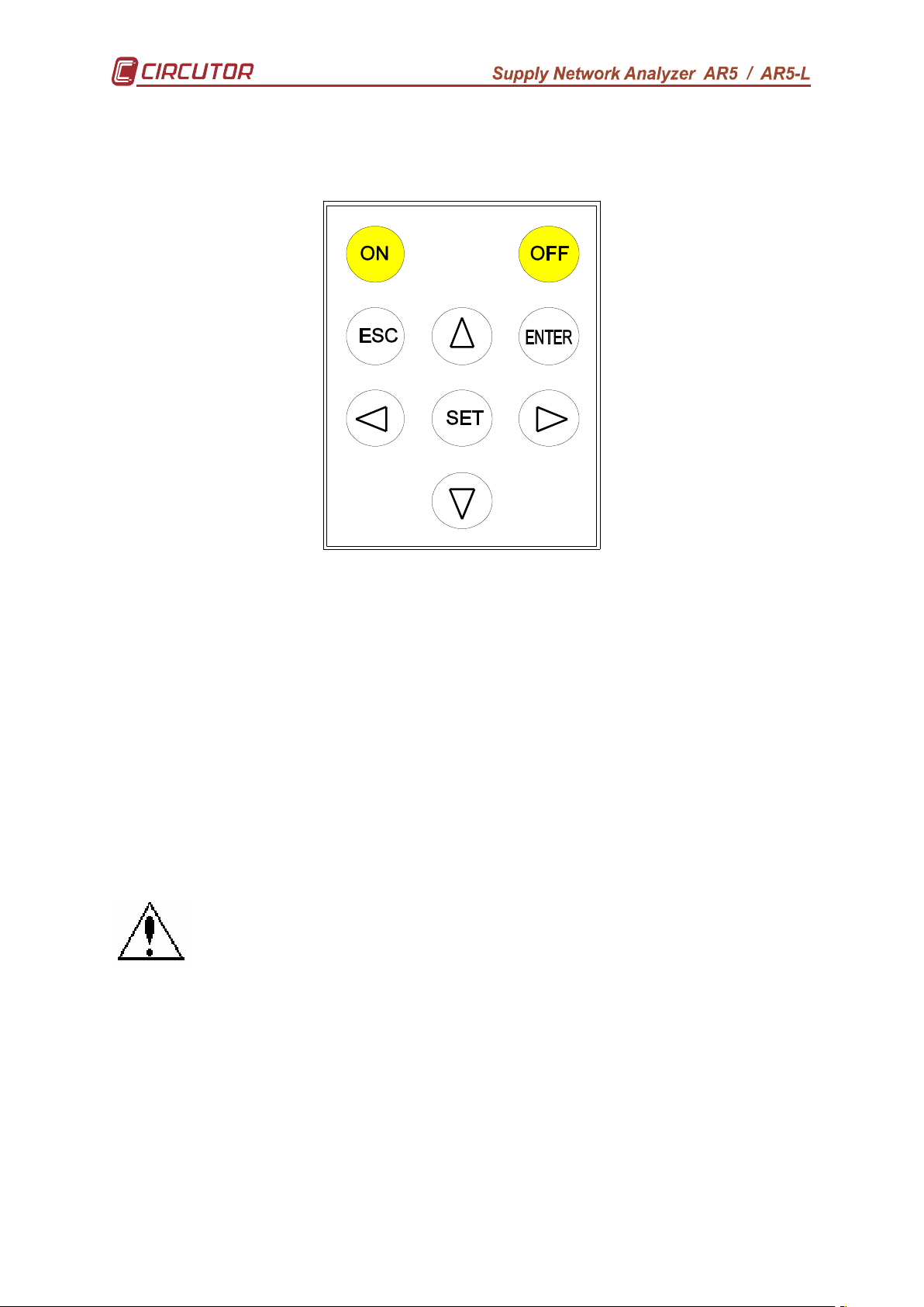
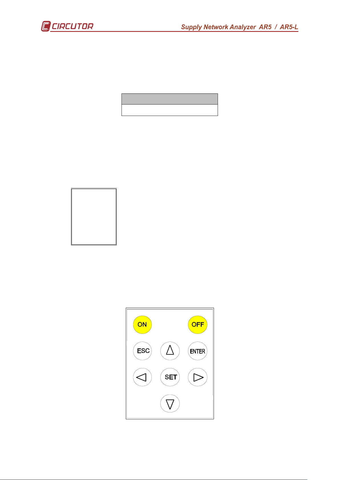
3.- KEYBOARD FUNCTIONS
The analyzer has a 9 buttons keyboard to perform configuration and
control actions of all the instrument options.
- [ON] to turn the analyzer on.
- [OFF] (Quick press) to turn on/off the display back-light.
- [OFF] (5 seconds press) to turn analyzer off.
- [6666], [5555], [4444] & [3333]. To select among several options.
- [SET] to access setting options.
- [ENTER] to validate a setting option or to program some parameters of the
visualization screens.
- [ESC] to select different visualization screens or to exit the setting actions.
However, most of keys are double functional: The own instrument
understands the meaning of the order at each case.
4.- Installation AND START-UP
The manual you hold in your hands contains information and
warnings that the user should respect in order to guarantee a proper
operation of all the instrument functions and keep its safety conditions.
If the instrument is not used according to manufacturer’s
specifications, the protection of the instrument can be damaged. Note that with
the instrument powered on, cover opening or elements removal actions may allow
accessing dangerous parts. Therefore, before any adjustment, replacement,
maintenance or repairing operation is carried out, the instrument must be
disconnected from any power supply source.
When any protection failure is suspected to exist, the instrument must be
immediately put out of service. Contact then with a qualified service representative.
4.1.- Steps necessary for the START-UP
9
Page 10

For the Star-up of the equipment and to let it ready to begin to register is
necessary to make the following steps.
1) Plug the battery, see point 11.-CHANGING THE BATTERY
2) Format the memory, see 6.4.3.-FORMAT: Formatting the analyzer internal
memory
3) Set the analyzer in hour, see point 6.1.4.-CLOCK: Internal clock
4) Charge the battery by a period of minimum 14 hours. .
10
Page 11
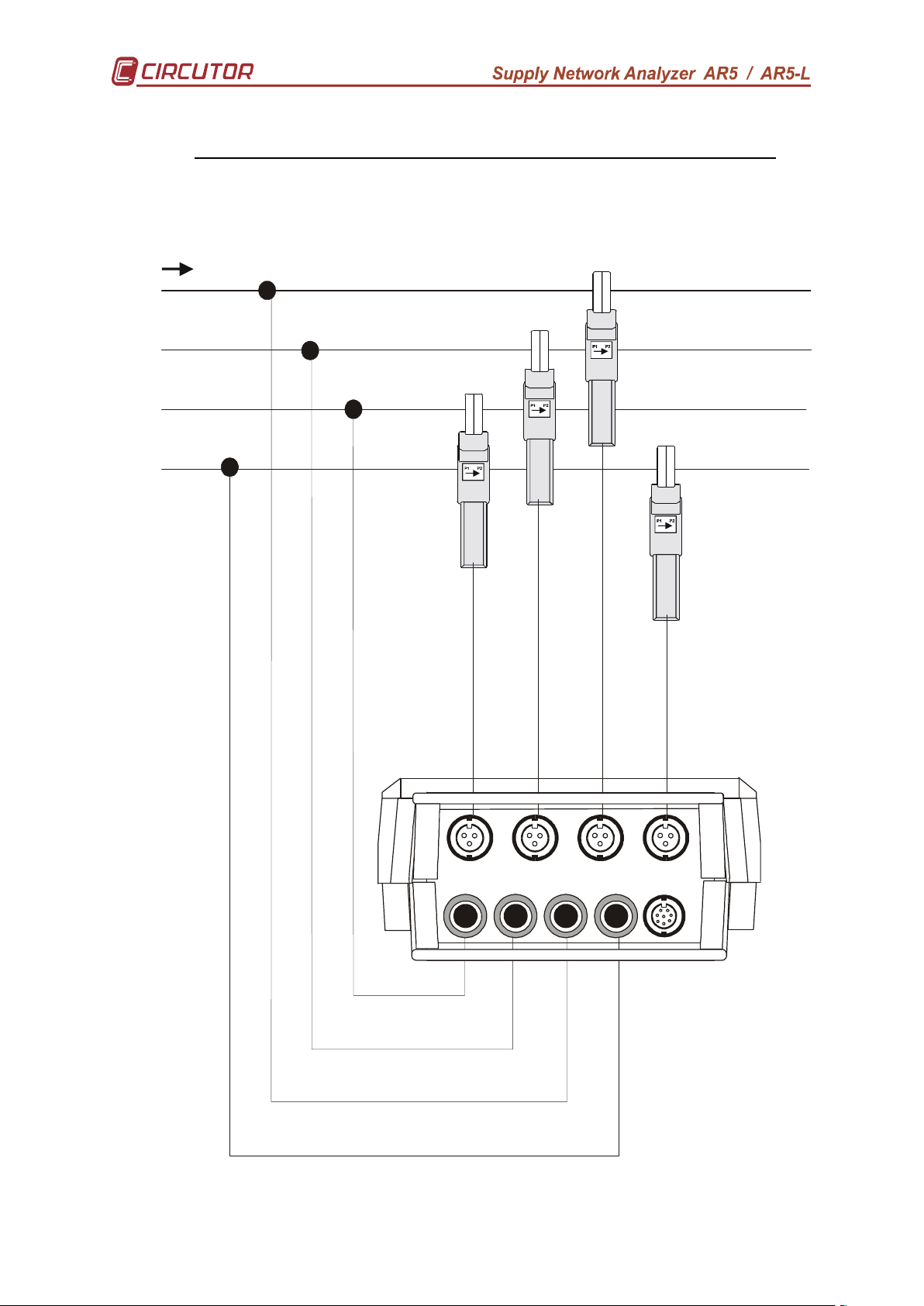
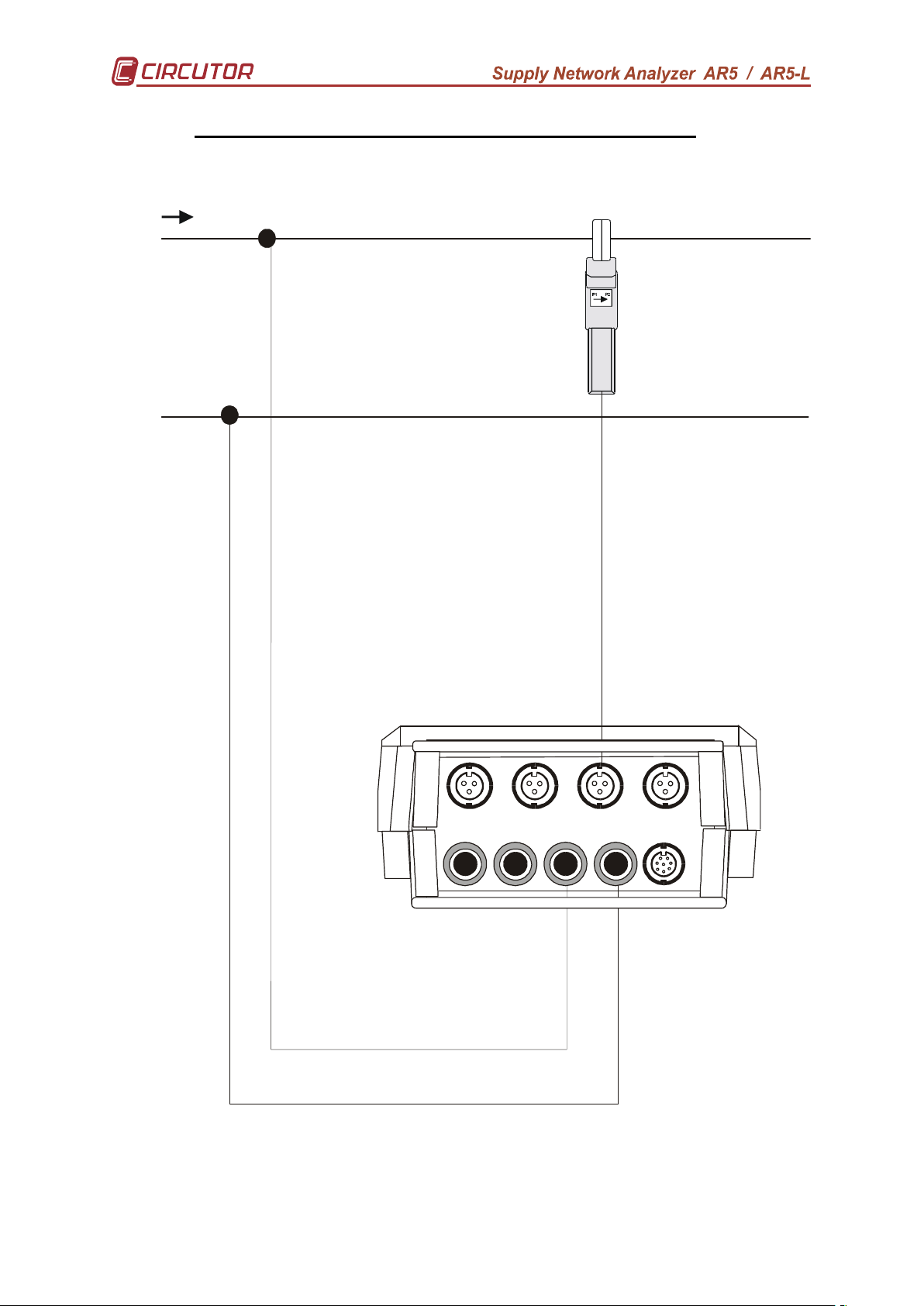
4.2.- Connection diagram
IL1
IL2
VL1
VL2
VL3
AUX
A.- CONNECTION DIAGRAM FOR THREE-PHASE - 4-WIRE – SYSTEM
This connection is only available for AR5-L model
( SET ---> SETUP ---> MEASURE ---> WIRING ---> 3Φ 4 WIRES)
L1
L2
L3
N
IL3
11
I
N
N
Page 12
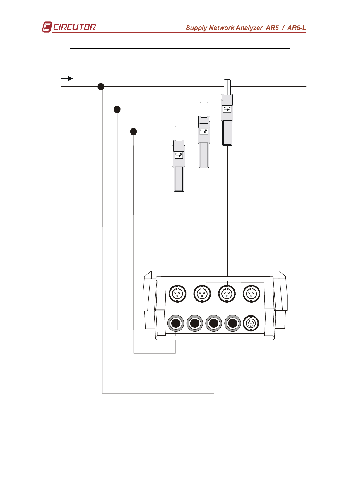
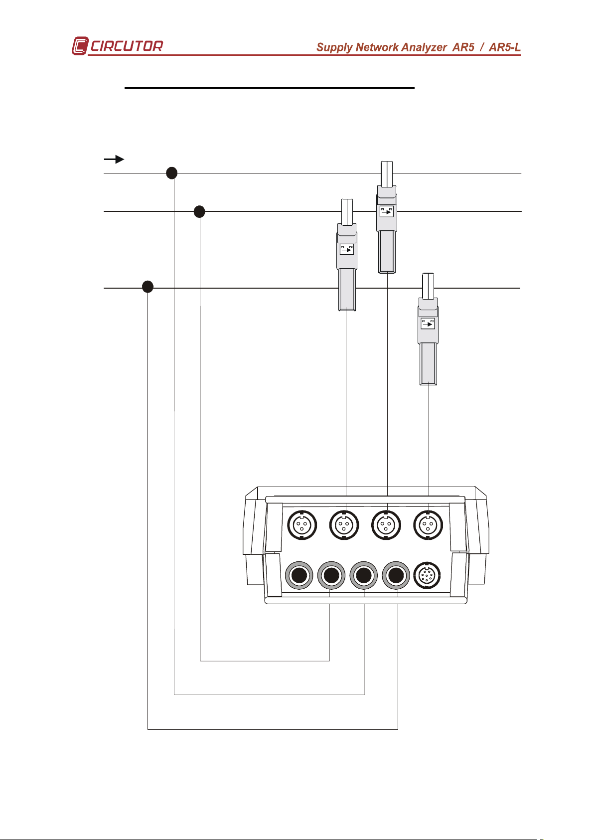
B.- CONNECTION DIAGRAM FOR THREE-PHASE - 3-WIRE - SYSTEM.
IL1
IL2
VL1
VL2
VL3
AUX
( SET ---> SETUP ---> MEASURE ---> WIRING ---> 3Φ 3 WIRES )
L1
L2
L3
IL3
I
N
N
12
Page 13
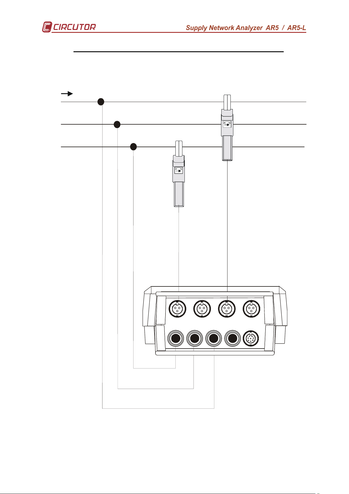
L1
IL1
IL2
VL1
VL2
VL3
AUX
L2
L3
C.- CONNECTION DIAGRAM FOR THREE-PHASE - 3-WIRE (ARON)
( SET ---> SETUP ---> MEASURE ---> WIRING ---> 3 PT – 2 CT
IL3
13
I
N
N
Page 14
L1
IL1
IL2
VL1
VL2
VL3
AUX
N
D.- CONNECTION DIAGRAM FOR SINGLE-PHASE - SYSTEM
( SET ---> SETUP ---> MEASURE ---> WIRING ---> 1Φ)
IL3
14
I
N
N
Page 15
L1
IL1
IL2
VL1
VL2
VL3
AUX
L2
N
E.- CONNECTION DIAGRAM FOR BI-PHASE - SYSTEM
This connection is only available for AR5-L model
( SET ---> SETUP ---> MEASURE ---> WIRING ---> 1Φ Split )
IL3
15
I
N
N
Page 16
4.3.- Starting the analyzer up
Before connecting the instrument to the mains, please consider following points:
5) Supply voltage: 100 V a.c. – 240 V a.c. , 50... 60 Hz.
The instrument must be energized by a supply circuit with protection earth terminal.
6) Maximum input voltage at the voltage measuring circuit:
500 V a.c. phase-neutral (CAT III)
Use always the voltage leads factory-shipped with the instrument.
7) Burden: 15 VA.
8) Operation conditions:
- Operation temperature: 0 ºC to 40 ºC.
- Operation humidity: 80% for temperatures up to 31ºC decreasing
linearly to 50% relative humidity at 40ºC.
9) Safety : Designed to meet protection category III 600V as per EN 61010.
10) Current measuring range: according to the current clamp used
Current clamps Measuring range
CP-2000-200 clamp 10 to 2000 A a.c. (scale 2000 A)
1 to 200 A a.c. (scale 200 A)
CPR-1000 clamp 5 to 1000 A a.c.
CPR-500 clamp 2,5 to 500 A a.c.
CP-100 (M1-U) clamp 0´5 to 100 A a.c.
CP-5 clamp 25 mA to 5 A a.c.
Flexible clamp Measuring range
C-FLEX 200-2000-20000 100 to 20000 A a.c. (scale 20000 A)
10 to 2000 A a.c. (scale 2000 A)
1 to 200 A a.c. (scale 200 A)
NOTE: It is always advisable to take measurements at the high range of the
scale to obtain a better accuracy.
To start measurement works with the analyzer:
11) Connect to the main with the factory-shipped cables. Also connect the protection
earth terminal to avoid possible disturbances over the analyzer.
12) Connect the voltage leads at each phase of the monitored system, as well as the
neutral when it exists.
13) Connect the Current clamps at each phase conductor. Each current phase must
coincide with its voltage phase.
14) Respect the connection modes shown at each diagram to correctly achieve
powers, PF and energies readouts.
16
Page 17

To turn the instrument on:
15) Press the switch <ON> at the analyzer frontal cover. The analyzer introduction
screen appears. The user can now select the operation mode program for the
analyzer
16) After some seconds, a screen allowing the choice of the analyzer program to be
used is shown up.
17) One the desired program has been selected, analyzer will check the type of
ammeter clamps connected to the analyzer. This process is only performed
when analyzer is turn on, and in case that the connected clamps does not
matches with the programmed ones, then the analyzer will automatically give the
option to change the ammeter clamp setting:
- Press <ENTER> to validate the suggested clamp setting. The new
transformation ratio will be set at the ratio detected in the clamp L1.
- Press <ESC> to exit the auto-checking process with no change in
the analyzer setup.
18) After some seconds the principal electrical parameters of the network are
displayed.
NOTE : If nothing is shown on display, a discharged battery or any problem
with the display contrast might exist.
Initial considerations after the analyzer start-up:
- Format the memory if necessary (see section 6.4.-FILES Menu).
- Clear maximum & minimum values as well as energy counters if necessary
(see section 6.5.- CLEAR menu: Deleting data).
- Open a file with the desired name (see section 6.1.2.3.- NAME: recording file
name). All data will be automatically saved in this file until a new one is
opened. The analyzer internal memory can contain several files (different
analysis).
Warning :
Take into account that when the memory is formatted all previously stored
data is lost. When opening a new file (a different name that the previous one) the
internal memory is not deleted.
When starting new measurements at any installation the meter
programming must be checked and modified if necessary (following steps attached
at Section 6.- PROGRAMMING THE ANALYZER) Otherwise, the analyzer will work
according the last used program (this is saved in memory even after powering the
meter off).
Points to be mainly checked would be:
- Ratio of Current clamps (see section 6.1.1.2.-)
- Voltage transformer ratio (see section 6.1.1.2.-)
- Recording period (see section 6.1.2.1.-)
17
Page 18

4.4.- Loading a new program
The analyzer has an internal memory to save diverse operation mode
programs to be used by the user.
Before starting this action, check that analyzer is supplied through the power
supplier set.
To load any program, follow these instructions precisely:
• Turn the meter off.
• It is necessary to load a coprocessor that comes in a cartridge to part, and
that must settle only in the position of the coprocessor (the last position of
the list)
• Connect the cartridge into the appropriate input placed in the power
supplier set.
• Turn the meter on.
• Select with the keys [5555] & [6666] that you want to perform a program loading
action (LOAD PROGRAM). Press [ENTER] or wait for a while to confirm
this operation.
• Select the position to save the program into.
• The analyzer will perform a test to check that the cartridge has been
properly connected.
• If an inserted cartridge is detected, then the program will be loaded.
• Once the loading is completed, reset the meter.
• If no cartridge was found or a loading mistake occurred, reset the meter
and redo the above steps.
A cartridge will be only valid for the analyzer, which the
program was for the first time loaded into.
Note on the cartridge the serial number of its related
analyzer.
18
Page 19

4.5.- Turn the analyzer off
To turn the analyzer off proceed as follows:
• If no password is set (Default option):
- Press the key [OFF] during 5 s
• If a password is set:
- Press the key [OFF] during 5 s
- You will see in display:
PASSWORD
- Enter the set password or, if this has not been previously modified,
the default password [3333] [SET] [5555] [SET].
- Press again the key [OFF]. (In case of a correct password, the
analyzer will turn off).
4.6.- Back-light
To turn the display backlight on/off just make a quick press on the key [OFF].
4.7.- Choice of the working program
The analyzer can hold in memory different operation mode programs. The
choice of the program to be used is done when starting the meter up.
• Turn the analyzer on.
• A list of available programs will be shown on display.
• Use keys [5555] & [6666] for the choice of the desired program.
• Press [ENTER] or wait for a while to confirm this operation.
CHECK THE SETUP !!!!
All the programs have an independent disposition, therefore, the disposition
will be due to always verify, to assure an appropriate operation.
For instance, if the setup is modified at the “ANALYZER” program, these
modification will not be valid for the “HARMONIC” program, and so for any program.
19
Page 20

4.8.- Recharging the analyzer battery
The analyzer is equipped with an intelligent energy charging system. This
means that the instrument continuously checks in an automatic way the state of the
battery, thus the charging process stops when the battery is at its maximum charge
level. The span life of the battery is so increased.
To enable the battery charging proceed as follows:
• Connect the power supplier set to the main.
• Connect the analyzer to the power supplier set.
• Turn the analyzer on by pressing button [ON].
Provided the analyzer is connected to the main through the power supplier set,
the battery is self-recharging.
If the battery is exhausted, the charging process should last at least 3 hours
with no interruption; although a charging period of 16 hours is advisable in order to
completely charge the battery.
The analyzer shows on screen a battery charge indicator:
NOTE: The battery charge is only used while the ANALYZER is turn on.
4.9.- Energy saving
The ANALYZER has an energy saving system. So, if no key is pressed for at
least 5 minutes, the display is automatically off. The analyzer continues the recording
data process but nothing appears on display.
The display will automatically be active when any key is pressed (excepts for
the key [ON] that causes no effect).
20
Page 21

5.- DATA VISUALIZATION ON DISPLAY
All measured instantaneous values, as well as maximum and minimum, can
be read on a 160 x 160 pixel, liquid, crystal display (back-light ability).
An indication of the type of data being displayed is shown at the upper right
corner.
5.1.- Base screen
5.1.1.- Screen of instantaneous values
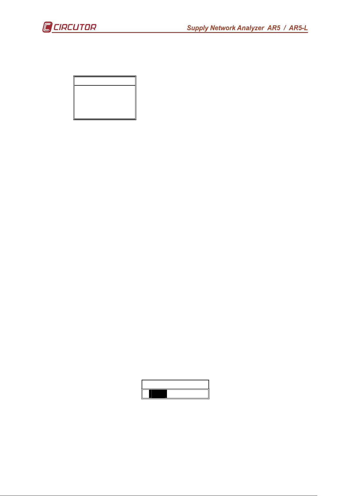
When powering the analyzer on, the display will show:
HARMONICS
INST L1 L2 L3 III
Vp-n
220 221 223 221
A
kW
kvarL
kvarC
P.F.
Hz
kVA
AN
kWh 0.000
kvarLh 0.000
kvarCh 0.000
25 / 10 / 04 17 : 31 : 29
Instantaneous value screen
Voltage: Readout of the instantaneous RMS value measured at each phase
(L1, L2 & L3) and the average value of the instantaneous values of the three phases
(III).
Current : Readout of the instantaneous RMS value measured at each phase
(L1, L2 & L3) and the average value of the instantaneous values of the three phases
(III).
Active power: The active power is calculated from instantaneous voltage and
current data. The readout gives the instantaneous values of the active power of each
phase and also the three phase total instantaneous active power, which is the
addition of each phase value.
Inductive reactive power: The inductive reactive power is calculated from
instantaneous voltage and current data. The readout gives the instantaneous values
of the inductive reactive power of each phase and also the three phase total
instantaneous inductive reactive power, which is the addition of each phase value.
Capacitive reactive power
: The capacitive reactive power is calculated from
instantaneous voltage and current data. The readout gives the instantaneous values
21
Page 22

of the capacitive reactive power of each phase and also the three phase total
instantaneous capacitive reactive power, which is the addition of each phase value.
Power factor : Readout of the power factor of each phase and the three phase
average value.
Frequency : Readout of the instantaneous value of the frequency (Hz).
Neutral Current : Readout the value measured of the neutral current. (only in
AR5-L model)
Apparent power : Readout of the three phase total instantaneous apparent,
which is the addition of each phase value.
Energies: Readout of active, inductive reactive, and capacitive energy
counters from the moment that the energy counters were reset to zero (see section
6.5.-)
Time and Date. (time/date): Readout of present time and date. For any
modification, see section 6.1.4.- CLOCK: Internal clock.
5.1.2.- Screen of maximum and minimum values
HARMONICS
MAX L1 L2 L3 III
Vp-n
220 221 223 221
A
kW
kvarL
kvarC
P.F.
Hz
kVA
AN
kWh -0.000
kvarLh -0.000
kvarhC -0.000
25 / 10 / 03 17 : 31 : 29
Screen of maximum values
An indication of the type of data being displayed is shown at the upper
right corner: INST (Instantaneous), MAX (Maximum) or MIN (Minimum).
Maximum and minimum values displayed correspond to the maximum
and minimum values obtained from the instantaneous values.
The negative energy counters are then displayed in place of positive
energies.
22
Page 23

5.2.- Other visualization screens
Through the key [ESC] other additional screens can be displayed.
This screen might lightly vary according to the user-selected measuring circuit
type (Wiring).
5.2.1.- Visualization of 3 parameters in a big size mode
Three instantaneous parameters of your choice can be bigger size displayed
for a clearer reading.
INST HARMONICS
Vp-n
L1
Vp-n
L2
Vp-n
L3
09 / 01 / 04 17 : 31 : 29
220
221
224
NOTE : The 3 parameters to be displayed can be selected as follows:
a.- Pressing: SET --> DISPLAY ---> EXPAND.
b.- Directly pressing [ENTER]:
To modify:
- Select with the keys [6666], [5555], [4444] or [3333] the desired parameter and press
[SET] to validate the choice.
- Select “CLEAR ALL “ on display + [SET] to clear all parameters.
- [ENTER] to validate the choice or [ESC] to exit with no modification.
Only three parameters can be selected at once.
23
Page 24

5.2.2.- Bar graphs
Simultaneous graphic representation on display of the three phases (L1, L2 &
L3) of the selected parameter.
HARMONICS
INST
Vp-n
250
170
0
25 / 06 / 04 17 : 31 : 29
L1
220
L2
221
L3
223
NOTE : Both the parameter to be displayed and the graphic scale can be
selected as follows:
a.- Press: SET --> DISPLAY ---> BAR.GR.V
b.- Directly pressing [ENTER]:
Select with keys [6666]or [5555] the desired parameter: Vp-n, Vp-p, kVA, Hz,
PF, kvarC, kvarL, kW & A. Press [ENTER] to validate the choice.
Set the scale offset (ZERO SCALE) with keys [6666], [5555], [4444], [3333], [SET] &
press [ENTER] to validate the operation.
Set the full-scale value (FULL SCALE) with keys [6666], [5555], [4444], [3333], [SET]
& press [ENTER] to validate the operation.
24
Page 25

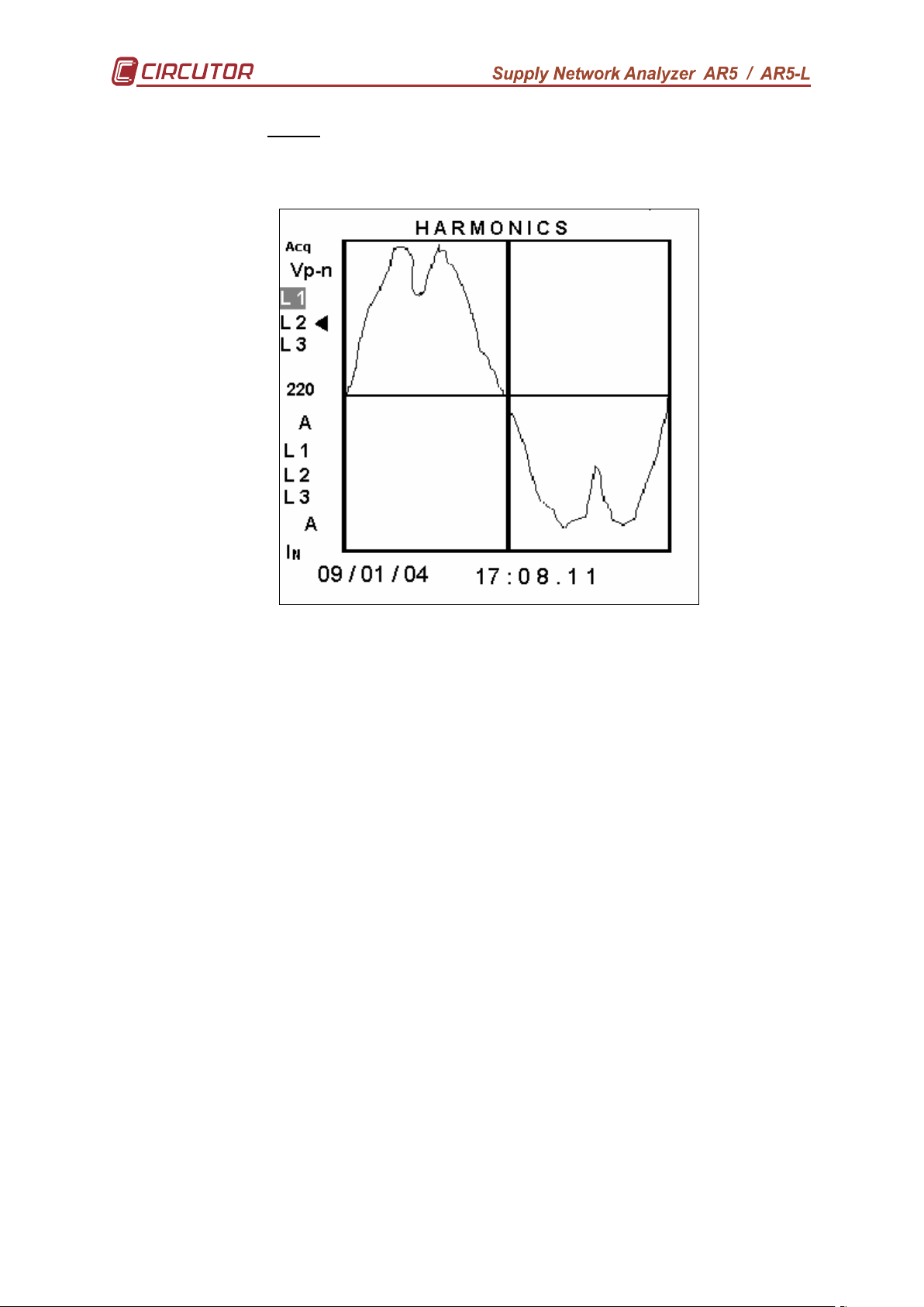
5.2.3.- Oscilloscope
The display concurrently shows the wave forms of voltage and current of each
phase (L1, L2 & L3).
5.2.3.1.- Three phases: Voltage - Current.
Both the voltage and the current waveforms of the captured cycle are
shown on the screen together with their respective effective values.
With [5555] & [6666] keys select the operation to be carried out. After pressing
the [ENTER] key the reverse video mode text indicates that one of the
following operation will be carried out:
− “Acq” : a new waveform is acquired.
− “L1”, “L2” o “L3” : zoom on the waveform of the selected phase.
− “IN” : zoom on the waveform of the neutral current. (only in AR5-L
model)
With the [4444] & [3333] keys you can move along the ordinate axis, and see
the instantaneous voltage and current.
With the [ESC] key the Setup menu is shown.
25
Page 26
5.2.3.2.- Zoom.
This window shows the captured signal in detail.
The 3 sign, indicates the kind of signal and the phase of the waveform
that is being zoomed.
Again, with the [4444] & [3333] keys you can move along the ordinate axis,
and see the instantaneous voltage and current.
With [5555] & [6666] keys select the operation to be carried out. After pressing
the [ENTER] key the reverse video mode text indicates that one of the
following operation will be carried out:
− “Adq” : a new waveform is acquired.
− “L1”, “L2” o “L3” : zoom on the waveform of the selected phase.
− “IN” : zoom on the waveform of the neutral current. (only in AR5-L
model)
− If the selected phase is marked with the 3 sign, you will next see
the overall harmonic factorization of the selected signal
With the [ESC] key the Setup menu is shown.
26
Page 27

5.2.3.3.- Harmonic factorization.
The network analyzer has one screen where you can see the harmonic
factorization of the signal that has been captured.
The 3 sign, indicates the kind of signal and the phase of the waveform
that is being zoomed.
With the [4444] & [3333] keys you can move the 5555 arrow along the ordinate
axis and in the table below it the magnitude of the corresponding harmonic
is shown.
With [5555] & [6666] keys select the operation to be carried out. After pressing
the [ENTER] key the reverse video mode text indicates that one of the
following operation will be carried out:
− “Acq” : a new waveform is acquired.
− “ODD” or “EVEN” : it allows you for switching between even or odd
harmonics.
− “L1”, “L2” o “L3” : it carries out the harmonic factorization of the
selected phase
− “IN” : zoom on the waveform of the neutral current. (only in AR5-L
model)
− If the selected phase is marked with the 3 sign, the next screen to
be shown is the initial one in which the voltage and current of the
three phases are shown (see section 5.2.1.-).
With the [ESC] key the Setup menu is shown.
27
Page 28
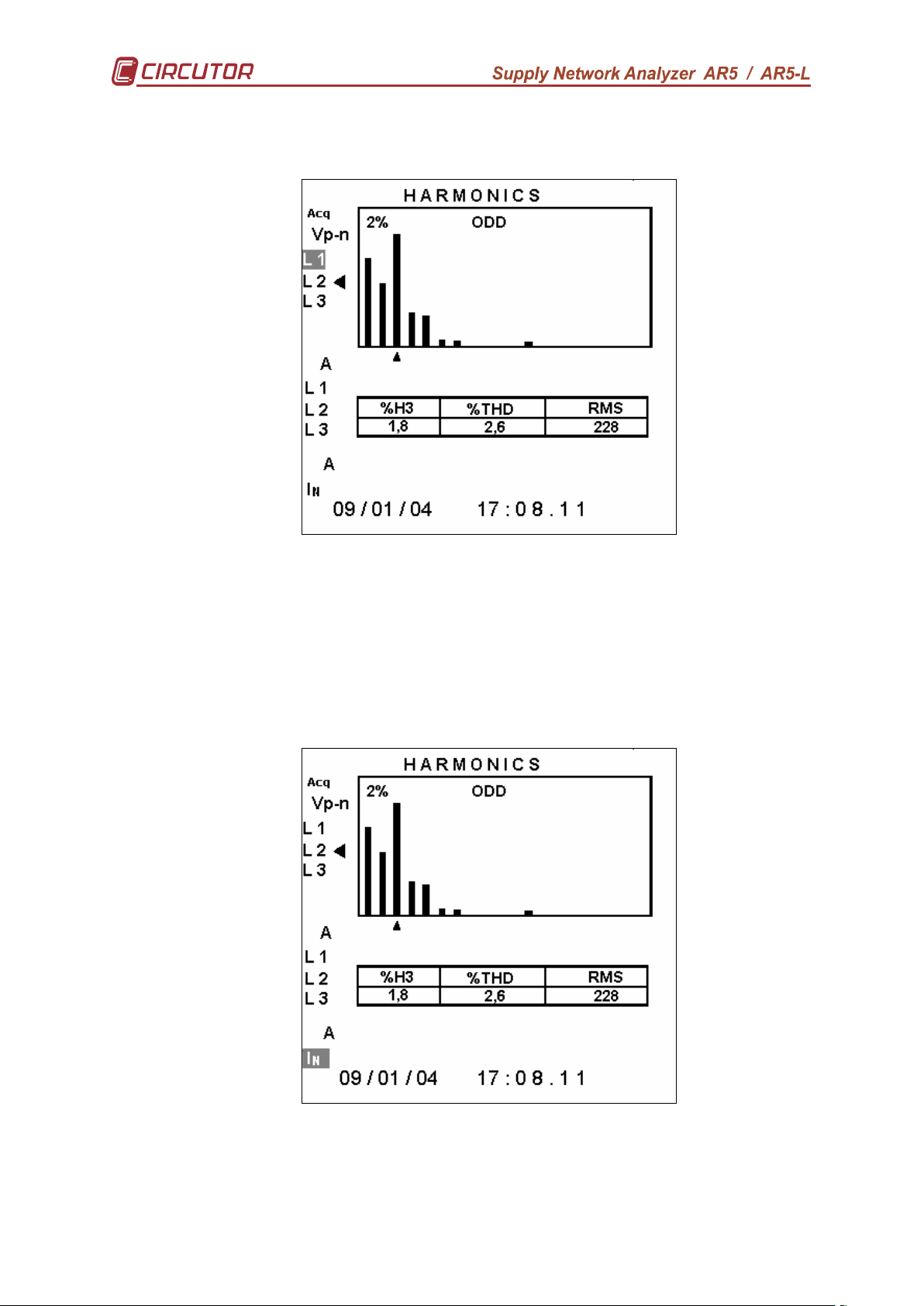
• Voltage and current harmonic content.
Where:
• %Hx : stands for the amplitude % of the selected harmonic referred to
the fundamental.
• %THD : stands for the % of harmonic content referred to the
fundamental
• RMS : stands for the signal true RMS value
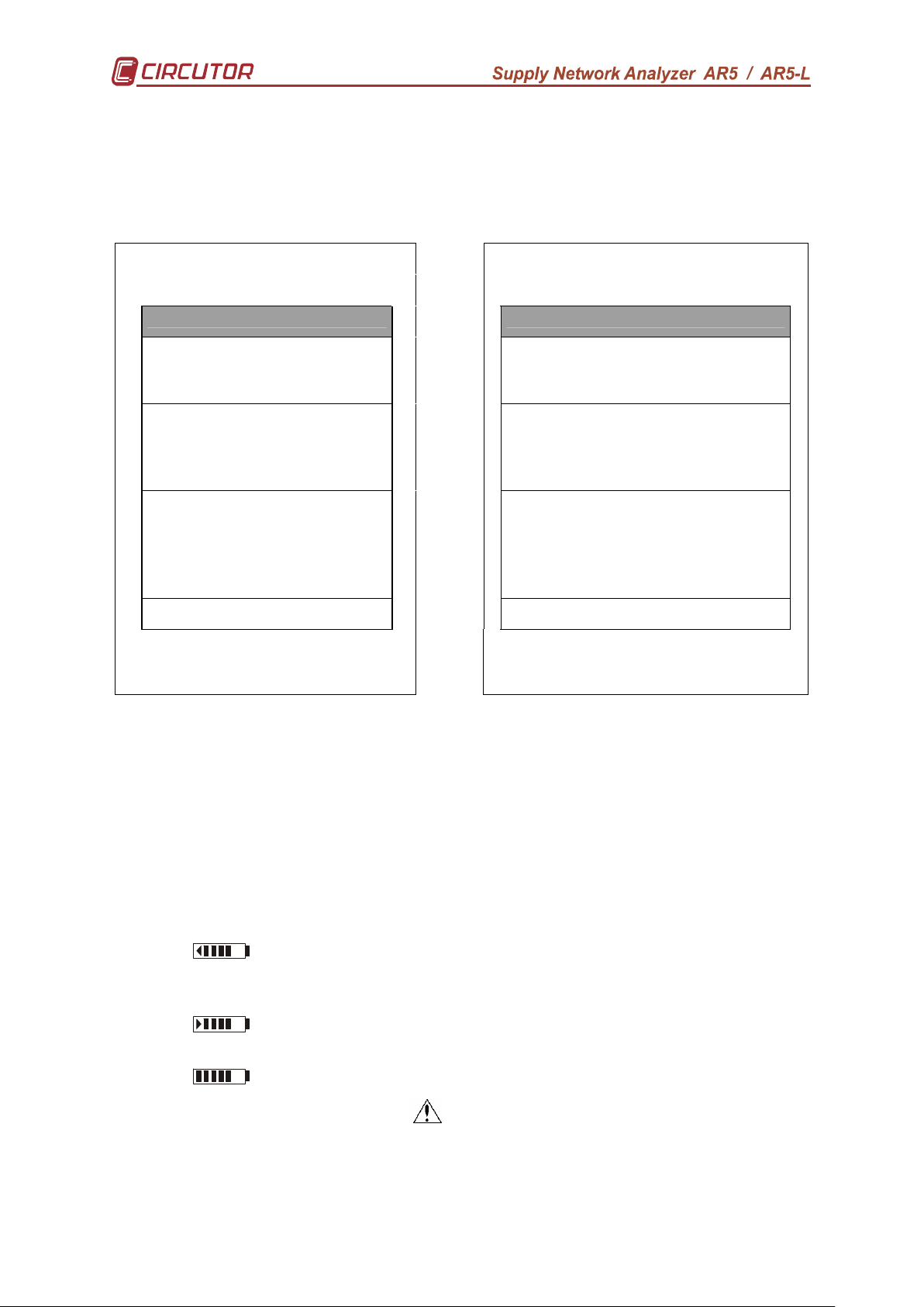
• Neutral current harmonic content.(only in AR5-L model)
Where:
• %Hx : stands for the amplitude % of the selected harmonic referred to
the RMS value.
• %THD : stands for the % of harmonic content referred to the RMS value.
• RMS : stands for the signal true RMS value.
28
Page 29
5.2.4.- Setup visualization
This screen permits to check all Setup parameters in the analyzer.
The screen on the left is the one shown on the analyzer’s display. The screen
on the right explains the meaning of each term.
HARMONICS
HARMONICS
SETUP SETUP
Mea su re: 3 Ф wir e
1/1 V
100 0A - IN=10 0A
Fil e: S td-p rog .S TD
00: 15:00 Ha rm. 50
Cyc lica l
RT xd : xxh : xxm :xxs
Tri gger: A ut o
0 0
00/ 00/92 00: 00:00
00/ 00/92 00: 00:00
Type of me asur in g c ircu it
Nam e and t yp e of file
Tri gger pa ramet er
V.T . rat io
C.T . ra tio /N eu tra l C.T .
Rec or din g pe ri od H ar mo nics
Mem ory typ e
Tim e o f re gi st er
Max. Val ue Min .
Val ue
Tri gger: d at e O n
Tri gger: d at e O ff
Com : 960 0/ NO /8/ 1
25/ 10/03 7 :31:2 9
Com mun ic at io n p arame ters
Pre se t dat e
5.3.- Warning messages
Some warning messages can appear at the visualization screens. These
messages inform about the ANALYZER performance:
- STOP: The analyzer is not recording data.
- RECORD: The analyzer is recording data.
- TRIG?: Trigger conditions are not met. No data is being recorded.
- M. Full: Memory is full.
- M.Error: There is an error in the memory. The memory must be formatted.
- Analyzer battery charge status. When only the symbol 3333is shown,
it means that the battery is very low and the analyzer might turn off at any
moment.
- The battery is charging. The user can also see the accumulated
battery charge level.
- Full battery charge.
- WARNING MAX 500 V : The maximum allowable phase to neutral
voltage of 500 V has been exceeded during the measuring process. When
measuring phase-to-phase voltages the limit is set at 866 V.
29
Page 30
6.- PROGRAMMING THE ANALYZER
To accessing ANALYZER setup options press the key [SET]. The analyzer
will then inquiry for a password that consists of a key sequence to be pressed (the
user has 15 seconds to press this sequence). If the default password has not been
modified, then the following key sequence must be followed:
PASSWORD
[3333] [SET] [5555] [SET]
Standard Password
Once this password is entered, the analyzer will permit the user to modify any
Setup parameters.
All programs have an independent setup, therefore, the setup must be always
check to ensure a proper operation, since any modification will only affect the active
operation program.
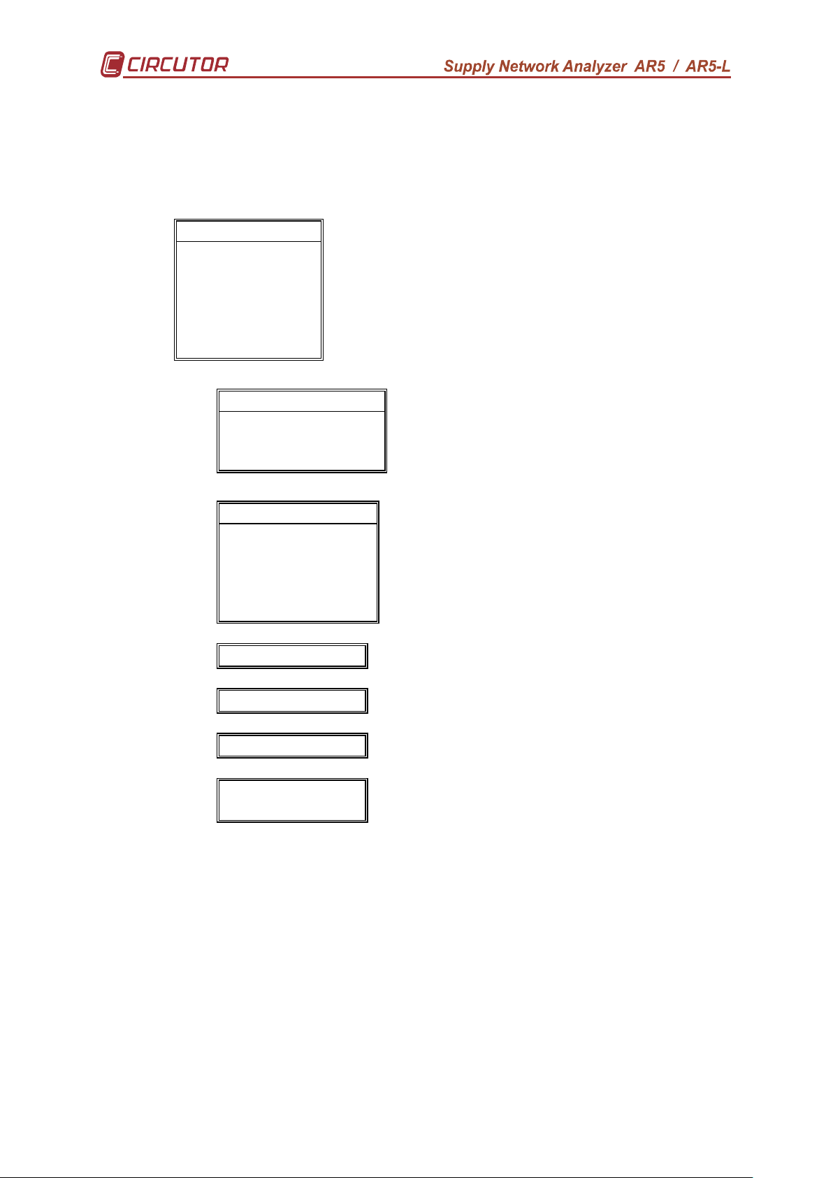
Diverse setting MENUS are available:
SETUP
DISPLAY
RUN
FILES
CLEAR
OFF
LANGUAGE
• Select one option with keys [6666] & [5555].
• To access any menu option use [8888] or [ENTER].
• To close the menu press [3333] or [ESC]. If this key is used when only the
main menu is open, this is closed. If any modification over any setup
parameter was done, before closing a confirmation of setup change is
requested on display.
INITIAL MENU
30
Page 31
6.1.- SETUP menu
The analyzer can be user-configured to different performances involving its
data analysis and recording modes, as it is followed shown:
SETUP
MEASURE
RECORD
COMM
CLOCK
PASSWORD
RECALL
MEASURE
WIRING
PT/CT
SETUP menu.
4 wires / 3 wires / Aron / Single-phase / Bi-phase.
V and A transformation ratios.
RECORD
PERIOD
TRIGGER
NAME
PARAM
COMM Baud / Parity / Bits / Stop bits.
CLOCK DD/MM/YY hh:mm:ss.
PASSWORD Setting the analyzer password
RECALL Standard.
hh:mm:ss ( 1 s to 4 h ).
Level, Time, Off.
File name ( 8 characters) and memory type.
Special file parameters.
Recall Setup sure <yes > <no>.
31
Page 32

6.1.1.- MEASURE
Use this option to set measuring conditions: CONNECTION MODE SETTING
( 3 or 4 wires, Aron, single-phase or bi-phase) and VOLTAGE and CURRENT
TRANSFORMATION RATIOS SETTING.
MEASURE :
WIRING
PT / CT
3Φ 3 Wires, 3Φ 4 Wires, 3PT–2CT, 1Φ y 1Φ Split..
Prim. V, Second. V, Prim. I
6.1.1.1.- WIRING: Circuit type
Choice of the circuit type to be analyzed (rotary input).
− 3Φ 4 Wires: To measure Three-phase systems with Neutral wire. (only in
AR5-L model)
− 3Φ 3 Wires: To measure Three-phase systems with Neutral wire. For this
arrangement 3 current clamps must be used.
− 3PT-2CT: To measure Three-phase systems with Neutral wire. For this
arrangement only 2 current clamps must be used.
− 1Φ: To measure Single-phase systems.
− 1Φ Split: To measure Bi-phase systems, composed by 2 Phases and the
Neutral wire. (only in AR5-L model)
Always that the measuring circuit type is modified, parameters
selected to be recorded must be checked.
6.1.1.2.- PT/CT : Transformation ratios
Voltage and current transformation ratios setting. The program will
sequentially inquire for following data:
− PRIM. V: Voltage transformer primary value.
− SEC. V: Voltage transformer secondary value.
− PRIM. I: Current transformer primary / Current clamp primary, used for
measuring the line currents.
− PRIM. IN: Current transformer primary / Current clamp primary, used for
measuring the neutral current. (only in AR5-L model)
NOTE 1 : If voltage is directly measured (no voltage transformer is used), you
must set PRIM.V = 1/SECV.V = 1.
NOTE 2 : PRIM. I & PRIM I
a) The ratio of the Current clamp to be used.
b) In case of a high voltage system, the measurement will be carried out through the
secondary of current transformers. A shunt ATS-III 5 A a.c./ 2 V a.c. or CP5 clamp will
be then required to enter the measurement signal into the analyzer (Never directly
connect the 5 A signal to the analyzer.). For this case, the C.T. primary must be set at
the primary value of the C.T. used for measuring purposes.
Ratio set must be modified for each Current or transformer type change to avoid
measurement mistakes. Standard clamps give a voltage output (generally 2 a.c. at fullscale).
NOTE : Secondary is always set at 2 V a.c. (it is not user-programmable).
--> This option permits to program:
N
6.1.2.- RECORD menu
32
Page 33

The recording conditions are here user-programmed:
RECORD
PERIOD
TRIGGER
NAME
PARAM
6.1.2.1.- PERIOD: recording period
All values measured by the analyzer can be periodically saved in memory.
The recording period (time period between each record) is user-definable.
Each record consists of the average values measured during the pre-defined
period. This recording period can be from 5 s to 4 h
¡ NOTE! If a period longer than 4 hours is programmed, the display will show
an error message during some seconds:
hh:mm:ss ( 1 s to 4 h ).
LEVEL, TIME, OFF.
File name (8 characters) and memory type.
Parameters stored by the analyzer when selecting an STD file
" xx:xx OUT OF RANGE “
33
Page 34

6.1.2.2.- TRIGGER: Trigger conditions
TRIGGER
LEVEL
TIME
OFF
You can program here certain conditions (Trigger) so that values are saved in
memory only when these conditions are met.
Two types of trigger conditions are available:
1) Time trigger (TIME): DATE/TIME of ON (starting measurement
process), &/or OFF (ending measurement process).
2) Parameter trigger (LEVEL): you can set a maximum threshold
(measured values must be higher) &/or a minimum (measured
values must be lower) that define the value range within the
recording actions are performed (thus, for instance, the voltage to be
higher than a certain level, or the current lower than another one,
etc.).
3) OFF: Use this option to cancel all data programmed at former
options.
If the defined trigger conditions are met, the analyzer stores data to its internal
memory (STORE ON); and, on the contrary, no information is stored to memory
(STORE OFF) and the display will show the message TRIG?.
• LEVEL:
Lets to set the trigger for a parameter, as well as its maximum and minimum
range-limiting values.
- PARAM: Choice of the parameter for the trigger condition: (rotary input).
- Select with keys [6666] or [5555] the desired parameter:
Vp-p, Vp-n, A, kW, kvarL, kvarC, PF, Hz, kVA, Auto (None).
- [ENTER] to validate the choice. ([ESC] to exit with no modification)
- MAX: Set here the maximum threshold: (numeric input).
- Select with keys [6666], [5555], [8888] or [3333] the desired value and press
[SET] to validate each figure.
- Select ““ on display + [SET] to delete a figure.
- [ENTER] to validate the total value or [ESC] to exit with no
modification.
- MIN: Set here the minimum threshold: (numeric input).
- Select with keys [6666], [5555], [8888] or [3333] the desired value and press
[SET] to validate each figure.
- Select ““ on display + [SET] to delete a figure.
- [ENTER] to validate the total value or [ESC] to exit with no
modification.
Note: the set value will be valid only if a trigger parameter was previously defined.
POINTS TO CONSIDER:
- If the selected parameter is voltage, current or any power:
34
Page 35

1) When setting the maximum and minimum values take into account the units:
Parameter Format
Voltage V. With decimals kV
ex. 230.V 230.0kV
Current A
Power kW
2) The trigger condition is met when either the instantaneous value of any of the
three phases (L1, L2 or L3) or the three phase value of the selected parameter
is higher than the maximum or lower than the minimum (the analyzer switch
from STORE OFF to STORE ON).
Minimum Maximum
STORE ON <------ ......STORE OFF...... -----> STORE ON
any any
lower value higher value
- If no TRIGGER condition is wanted, select AUTO when choosing the parameter
- If the frequency is selected, both the maximum and minimum values can be typed
with a decimal (xx.x).
• TIME:
Lets to set the time trigger, that is, to define the period to perform the data storage.
- TIME ON: When selecting this option the present ON conditions are shown on
display:
TIME .ON
00 /00 /00 00 :00 : 00
day/month/year hour:minute:second
Pressing [ENTER]: ON values on display are directly validated.
- To modify: (rotary input).
- Select with keys [8888] or [3333] the position to modify.
- Though keys [6666], [5555] the value of the selected position is increased or
decreased.
- [ENTER] to validate the total value or [ESC] to exit with no modification.
35
Page 36

- TIME OFF: When selecting this option the present OFF conditions are shown
on display; and the procedure is equal to the above one.
TIME .OFF
00 /00 /00 00 :00 : 00
day/month/year hour:minute:second
POINTS TO CONSIDER:
a) To void the time TRIGGER, all values must be zero.
b) If only the ON & OFF TIME are programmed (two DATES set to zero),
the defined time period will be cyclically repeated by the analyzer.
ADDITIONAL NOTES:
a) The analyzer will save data in memory only when both TRIGGER
conditions are met: Time (ON-OFF) and Parameter (maximum and
minimum). If any condition is not met, no value is stored to memory
(STORE OFF state). In case that trigger conditions are void (ON & OFF set
to zero, and parameter set to AUTO), all values will be saved in memory
according to the previously defined recording period.
b) If trigger conditions are met at any moment within the defined recording
period, the average values for the whole period will be saved in memory.
36
Page 37

6.1.2.3.- NAME: recording file name
File name setting (8 characters, with no extension) and file type setting
(Cyclical – Linear).
File name.
- Pressing [ENTER]: Text on display is directly validated.
- To modify: (alphanumeric input).
- Select with keys [6666], [5555], [8888] or [3333] the character to modify and press
[SET] to validate each character.
- Select ““ on display + [SET] to delete a character.
- [ENTER] to validate the total text or [ESC] to exit with no modification.
NOTES!
NAME
STD-PROG
a) If the typed name already exists in memory, when exiting setting actions, the
display will show:
“Overwrite file Sure? “ --> Do you really overwrite the file?
- If yes is answered, the previous file is deleted.
- If no is answered, setup menu is not exited, thus a new name can
be typed for the file, or the setting actions can be cancelled.
• File type.
Choice of the file type for data recording purposes:
- Cyclical: Cyclical/rotary memory (FIFO). When this file type is selected,
only one file can be simultaneously used.
- Linear: Linear memory. Once the memory is full, no more new data is
recorded by the analyzer.
Linear and cyclical files are not compatible between them.
The memory cannot simultaneously contain files of both types.
In case of a cyclical file, all the memory will be used by this file. No
memory can be allocated to another file.
If the type of file is changed, the memory will have to be formatted when
exiting setup.
37
Page 38

6.1.2.4.- PARAM: Choosing the parameters to be saved
As said before, parameters to be saved in memory are user-definable when
working with STD files.
Pressing [ENTER] previously user-defined parameters are automatically
validated.
- To modify:
Place over the desired parameter with keys [6666], [5555], [8888] or [3333].
Pressing [SET] the state of the parameter switches. Parameters to be
saved are on a black background, and the ones to be not save are on a
white background.
Placing over the text Inst (Instantaneous values) and pressing [SET], you
can now select the maximum values to be saved (MAX).
Placing over the text Max (Maximum values) and pressing [SET], you can
now select the minimum values to be saved (MIN).
Placing over the text MIN (Minimum values) and pressing [SET],you can
now select the parameters of harmonics that will be kept. Including the
number of harmonics(30 or 50), V and I for each phase and neutral current
(only in AR5-L model)
Press [ENTER] to validate the choice or [ESC] to exit with no modification.
Note:
- In case that have been selected some not-compatible parameters with the
active measuring circuit, when exiting Setup, analyzer will warn the user
about this fact and will automatically unselect such wrong parameters.
- If values the parameters to be stored are changed, when exiting setting
actions, the display will show:
“Error: New file should be created”
This message is shown since the change of parameters in an already existing file
is not allowed. Follow these instructions to change the parameters of a file:
1. If you want to keep the file name.
• Stop analyzer data recording process: SET -> RUN -> Stop.
• Exit SETUP.
• Delete the existing file: SET -> FILES -> DELETE.
• Modify the parameters to be saved: SET -> RECORD -> PARAM
• Enable the analyzer data recording process: SET -> RUN -> Run
• Exit SETUP.
2. If you want to change the file name.
• Change the file name: SET -> RECORD -> NAME.
• Modify the parameters to be saved: SET -> RECORD -> PARAM
• Exit SETUP.
38
Page 39

6.1.3.- COMM: Communication parameters
Program here the parameters of the built-in RS-232 serial output. When
selecting this option the present parameters are shown on display:
COMM
9600 NO 8 1
Baud / Parity / Length / Stop bits
- Pressing [ENTER]: values on display are directly validated.
- To modify: (rotary input).
- Select with keys [4444] or [3333] the position to modify.
- Though keys [6666], [5555] the value of the selected position is increased or
decreased.
- [ENTER] to validate the total value or [ESC] to exit with no modification.
6.1.4.- CLOCK: Internal clock
Use this section to set the analyzer internal clock in time: date / time and
displaying format.
When this option is selected, presently programmed values are shown by
display:
CLOCK TYPE
DD /MM/YY HH :MM:SS
After validating the date format, the present date and time will be displayed
according to the selected arrangement:
CLOCK
00 /00 /00 00 :00 : 00
Proceed similarly than for the former section.
MM/DD/YY HH :MM:SS
CLOCK TYPE
39
Page 40

6.1.5.- PASSWORD: Safety setting.
Set here the analyzer password configuration. This password will be required
to access the Setup menu. Thus, the manipulation of the analyzer by not-authorized
people can be avoided.
The password can be also required for turning the analyzer off.
The default password is:
PASSWORD
[3333] [SET] [5555] [SET]
Change of Setup access password:
Firstly enter the old password:
OLD PASSWORD
* * * *
Then enter the new password:
NEW PASSWORD
* * * *
Finally, confirm the new password:
CHECK PASSWORD
* * * *
During this password modification process, the following error messages can
be shown in screen during 5 s:
Incorrect
Old password
Incorrect
Check password
Turning the analyzer off when the password is enabled:
To avoid the analyzer to be accidentally turn off, or by not-authorized persons,
an optional password can be enabled to be inquired when the analyzer is turn off.
The procedure to follow when this password is enabled is:
1) Press the key [OFF] during 5 seconds.
2) You will see in display:
Wrong password
The confirmation of the new password has failed
PASSWORD
3) Enter the correct Password.
4) Press [OFF] again
The analyzer will turn off if the entered password is the correct one.
40
Page 41

6.1.6.- RECALL: Read configuration
You can here recall a standard configuration.
Set Standard..
sure?
<yes > <no>
- A confirmation is requested: “Recall Setup sure <yes> or <no>“. With keys
[4444] & [3333] select yes or no, and then press [ENTER].
A “Standard” operation program for the analyzer is available to be user-recalled.
Its features are:
- V.T. ratio (SET + V) : 1 / 1
- Current ratio : 1000 A
- Neutral current ratio : 100 A
- Measuring circuit : 3Φ 4 Wires .
- Period (SET + PERIOD) : 15 minutes
- TRIGGERS (Time and parameter) : All set to zero
- File name (FILE Name) : STD-PROG -- Linear
- Communication parameters : 9600, No, 8, 1
- RUN : RUN
- Password : [3] [SET] [5] [SET]
- Password for turning the analyzer off : NO
41
Page 42
6.2.- DISPLAY menu
DISPLAY
BAR GR.
EXPAND
CONTRAST
ANGLE
You can at this point define the options about the parameters to be visualized
on display, the graphic mode performance, ...
6.2.1.- BAR.GR.
To determine the parameter to be graphically displayed, in addition with its
scaling. Both maximum and minimum values of the graph are inquired for autoscaling performance.
Bar graphs
Expanded Param. (3 parameters).
Contrast
cosϕ or P.F
- Choice with keys [6666] or [5555].
- [ENTER] to validate selection or [ESC] to exit with no modification.
6.2.2.- EXPAND
To choose three instantaneous parameters to be bigger size displayed for a
clearer reading.
- Select with keys [6666], [5555], [4444] or [3333] the desired parameter, and enable or
disable each one with the key [SET].
- Select “CLEAR ALL “ on display + [SET] to clear all parameters.
- [ENTER] to validate the choice or [ESC] to exit with no modification.
6.2.3.- CONTRAST: Screen contrast
The user can here vary the contrast of the analyzer’s display:
- With the [4444] you can intensify the display contrast and with the key [3333]
this can be lowered:
CONTRAST
LOW HIGH %
42
Page 43

6.2.4.- ANGLE
To choose the parameter to be displayed between cosϕ or P.F (power factor)
NOTE: It’s not allow to save cosϕ data in memory. Only can be read on
display.
6.3.- RUN: data recording process status
You can here enable or disable the data collection and logging action in the analyzer.
RUN
Run / Stop
- With keys [6666], [5555] RUN or STOP is selected.
- [ENTER] to validate or [ESC] to exit with no modification.
6.4.- FILES Menu
Non-volatile analyzer internal memory is storing data up to its maximum
capacity. Once full, neither new data will not be saved in, nor stored data will be lost
(provided no incorrect operation is done).
When memory is full, the display will show: "MEMORY FULL".
FILES FILES MENU
DIR
DELETE
FORMAT
6.4.1.- DIR: Directory
This option shows on display a directory of all files saved in memory.
AR5-L - DIR
STD-PROG. STD xxxxx bytes File name / File size
dd / mm / yy hh : mm : ss Day / Time
TEST1. STD xxxxx bytes
dd / mm / yy hh : mm : ss
STD-PROG. STD xxxxx bytes
dd / mm / yy hh : mm : ss
...... / .............
Free bytes: xxxxxxxxxx Number of free bytes in memory
- Keys [6666] or [5555] allows reading more files in case that all files stored by
the analyzer cannot be shown in only one screen.
- Keys [ENTER] or [ESC] to exit.
6.4.2.- DELETE: Deleting a file
43
Page 44

You can here delete any file from the internal memory.
DELETE
STD-PROG. STD xxxxx bytes File name / File size
TEST1. STD xxxxx bytes
STD-PROG. STD xxxxx bytes
...... ............
- With keys [6666] & [5555] select the file to be deleted.
- [ENTER] to confirm selected file erasing. Once press, a confirmation is
required.
- Press key [ESC] to exit with no modification.
6.4.3.- FORMAT: Formatting the analyzer internal memory
This option lets the user to format the internal memory.
FORMAT
Once the format action over the internal memory is confirmed, a confirmation
is required. Take into account that this action will mean all stored data to be deleted.
Note: Do not turn the analyzer off during the memory format process,
otherwise the display will show an error message and the process should be redone.
6.5.- CLEAR menu: Deleting data
CLEAR DATA CLEARING MENU
ENERGY
MAX/MIN
ENERGY :
The analyzer has several energy counters, which keeps their values even
though the analyzer is powered off.
The ENERGY options lets the user to reset these counters to zero.
MAX/MIN:
The analyzer records in memory the maximum and minimum values of
measured values. These values are kept in memory even though the analyzer is
powered off.
Options MAX/MIN lets the user to clear maximum and minimum values.
Erasing energy counters
Erasing maximum and minimum values
44
Page 45
6.6.- Menu OFF: Enable / Disable Password.
In order to avoid an accidental manipulation of the analyzer, the analyzer can
be set to request for a password when the user wants to turn it off.
Password?
<Yes> <No>
- With the key [4444],[3333] you can select:
- YES: A password is requested to turn the analyzer off.
- NO: No password is required to turn the analyzer off.
- [ENTER] to validate the choice or [ESC] to exit with no modification.
6.7.- Menu LANGUAGE
It allows to select the language in which the menus will be presented.
Language
English
- With keys [6666] & [5555] select the language.
- [ENTER] to confirm selected language
Press key [ESC] to exit with no modification.
NOTE: This configuration is commune for all the programs.
7.- ANALYZER COMMUNICATIONS
To connection to PC of the analyzer must be done through the power supplier
set, which will be necessary connected to the main. Perform the connection using the
two wires factory-delivered with the analyzer.
One cable will link the analyzer to the power supplier set, and another cable is
a standard RS232 connector.
When starting communication tasks take into account:
• Communication parameters of the analyzer and the PC must fully coincide.
• The power supplier set must be plugged into.
• The analyzer cannot be into the setup menu.
CIRCUTOR has a software package that permits the user to retrieve stored
data in the analyzer to PC for a further complete analysis.
45
Page 46

8.- TECHNICAL SPECIFICATIONS
Supply voltage:
Through an external power supplier set 100 V a.c. – 240 V a.c.
Battery: 5VHAA 1200 (Ni-MH)
Frequency : 50...60 Hz
Burden : 15 VA
Operation temperature : 0 / 40 ºC
Altitude: ≤ 2000
Maximum relative humidity 85 % (no condensation)
Measuring circuit : Three (3 or 4 wires), ARON, single-phase and bi-phase
Safety : Category III - 600 V, as per EN 61010
Pollution degree 2
Indoor use
Voltage measurement:
Measuring range : 20 to 500 V a.c. (phase-neutral) CAT III
automatic scale adjustment
Other voltages : through suitable voltage transformers
Frequency : 45 to 65 Hz
Current measurement:
Measuring range: see available current clamps
Current transducer ratio : user-programmable
Measurement units : automatic scale adjustment
Built-in clock with rechargeable battery: Date and time
Display : LCD; 160 x 160 pixels (Back-light)
RS-232 output : serial type output
Internal memory : 1 Mb
Accuracy class:
Voltage ..................................... 0.5 % of readout ± 2 digits
Current ..................................... 0.5 % of readout ± 2 digits
Active power ............................. 1.0 % of readout ± 2 digits
Reactive power.......................... 1.0 % of readout ± 2 digits
Measuring conditions to assure accuracy class:
- Errors due to voltage and current transformer not included
- Temperature range : 5 ºC to 45 ºC
- Power factor : 0.5 to 1
- Measuring range : between 5 % and 100 %
MECHANICAL CHARACTERISTICS
Case : Portable case.
Dimensions : 220 x 60 x 130 mm
Connection terminals : input/output terminals
Keyboard/ display : in frontal panel
Weight: 0,8 kg.
46
Page 47
POWER SUPPLIER SET
80 V a.c. – 265 V a.c. / 12 V d.c.
CAT III: 85 – 225 V a.c.
CAT II : 225 – 265 V a.c.
RELEVANT STANDARDS
EN 60664, EN 61010, EN 61036, VDE 110, UL 94
_____________________________________________
EM EMISSION.
− EN 61000-3-2 (1995), Harmonics.
− EN 61000-3-3 (1995), Voltage variations.
− EN 50081-2 (1993), Industrial emission:
− EN 55011 (1994): Conducted (EN 55022 - Class B).
− EN 55011 (1994): Radiated (EN 55022 - Class A).
EM IMMUNITY.
− EN 50082-2 (1995), Industrial immunity.
− EN 61000-4-2 (1995), ESD.
− ENV 50140 (1993), EM Radiated field of RF.
− EN 61000-4-4 (1995), EFT burst.
− ENV 50141 (1993), RF common mode.
− EN 61000-4-8 (1995), 50 Hz H-field.
− EN 50082-1 (1997), Residential Immunity.
− EN 61000-4-5 (1995), Surges.
− EN 61000-4-11 (1994), Dips, Interruptions.
(as shown in the test report reference number: 08077IEM.002)
CASE SYMBOLS:
: Warning. Maximum allowable input voltage: 500 V
: Reinforced isolation
These products have been designed and manufactured with top quality
components and they can be recycled and reused.
Electrical and electronic products contain substances that can harm the environment
if they are not adequately treated.
This symbol means that electrical and electronic equipment should not be thrown with
other household appliances at the end of its useful life.
Please take the obsolete products being replaced to a waste collection point or
contact your local administration.
The European Union has established specific collection systems for electronic and
electrical equipment waste.
Please help us preserve the environment!
Register Number REI-RAEE (ES): 3338
47
Page 48

ACCESSORIES
− AR5 and AR5-L Programs
- FLICKER ............................CODE. M 80223
- DISTORTIONS ...................CODE. M 80224
- CHECK-METER .................CODE. M 80225
- FAST CHECK ....................CODE. M 80226
- LEAK..………………………CODE. M 80229
- FILE-VISION….....................CODE. M 8022A
- Software POWERVISION....Visit our web site
− Current measurement:
a) Through Current clamps (3 Clamps KIT):
¨ CP-2000-200 ...... ...... ...... ...... ...... ...... ...... ......CODE M 81045
¨ CPR-1000 ......………………….......................... CODE M 81044
¨ CPR-500 ..........………………........................... CODE M 81043
¨ CP-100 (M1-U) .................................................. CODE M 81042
¨ CPR-100 (For Neutral current measurement)....CODE M 81036
¨ CF-5 LEAK CLAMP………………………………CODE M 81331
¨ CP-5 ........................... ....…………………........ CODE M 81041
b) Through flexible Current clamps (3 Clamps KIT):
¨ C-FLEX 200/2000/ 20000 – Length 45 cm.................. CODE M 81141
¨ C-FLEX 200/2000/ 20000 – Length 80 cm.................. CODE M 81142
¨ C-FLEX 200/2000/ 20000 – Length 120 cm................ CODE M 81143
c) ATS-5 shunt (5 A / 2 V a.c.) + current transformers (../5 A) ....CODE M 89925
− Carrying case
- Carrying case for AR5 and AR5-L current clamps....... .. CODE M 89921
- Carrying case for AR5-L and AR5................................... CODE M 89901
- 1000 case (with protection rubber CPR-1000) ................ CODE M 89923
- 2000 case (with protection rubber CPR-2000) ................. CODE M 89924
9.- SAFETY WARNINGS
The user should take into account all installation instructions
referred in sections INSTALLATION AND START-UP, CONNECTION
INSTRUCTIONS and TECHNICAL SPECIFICATIONS of the analyzer.
Note that with the instrument powered on, the terminals could be dangerous to
touching, and cover opening or elements removal actions may allow accessing
dangerous parts. The analyzer has been designed and tested to meet IEC 348
standard and is factory-shipped in proper conditions.
48
Page 49

10.- MAINTENANCE
The analyzer does not require any special maintenance. No adjustment,
maintenance or repairing actions should be done over the instrument open and,
should those are essential, high-qualified operators must perform them. Spares
should be provided by manufacturer.
The batteries are rechargeable and should be provided by manufacturer
Before any adjustment, replacement, maintenance or repairing operation is
carried out, the instrument must be disconnected from any power supply source.
When any protection failure is suspected to exist, the instrument must be
immediately put out of service.
The own instrument design permits a quick replacement in case of damage.
NOTE: Occasionally clean the equipment with water and detergent using a
soft, damp cloth. Do not use abrasives or solvents. Completely dry the
equipment before using it again.
11.- CHANGING THE BATTERY
It is possible to change the battery with a simple an easy way. The battery is
placed in rear part of the analyzer.
Before opening the cover to disconnect all the connections of tension
and current
In order to change the battery, do the following steps.
If you wants to request a battery for replace the code it is M89904.
1. Remove the cover
2. Unplug the battery
3. Replace the battery (the
single connector enters
a position, not to force)
4. Place the cover
49
Page 50

12.- TECHNICAL SERVICE
For any inquiry about the instrument operation mode or in case of malfunction,
you can contact CIRCUTOR’s technical service.
CIRCUTOR S.A. - Aftersales Service
Vial Sant Jordi, s/n
08232 – Viladecavalls (SPAIN)
Tel: (+34) 93 745 29 00
Fax: (+34) 93 745 29 14
e-mail: sat@circutor.es
50
Page 51

A. CABLE ARRANGEMENT
4
5
6
Different cables used with the analyzer have following arrangements:
• Communication cable RS232: PC - Power supplier set
• Power supply/Communication: Power supplier set - analyzer.
1
7
2
3
PC POWER SUPPLIER
SET
2 3
3 2
5 5
7 8
8 7
POWER
SUPPLIER SET
1 1
7 2
6 3
5 4
2 5
4 6
3 7
AR5-L
AR5
51
Page 52

B. QUICK GUIDE
Menu Description Options Standard
Setup
Display
Run Enabling/Disabling data recording Stop / Run Run
Files
OFF Request for a password to turn the analyzer off. Yes
LANGUAGE In order to choose the language with which it is wanted to work English / Español
Measure
Record
Comm Communication parameters setting 9600,n,8,1
Clock Analyzer’s date and time setting
Password Password change
Recall Recalling a Standard configuration Standard
Bar Gr.
Expand
Contrast Contrast
Angle
Dir Directory of stored files
Delete Deleting a file
Format Clearing all memory content
Energy Clearing energy counters Clear
Max/Min Clearing maximum and minimum values
Circuit Choice type of measuring circuit. 3 wires
4 wires*
Aron
Single-phase
Bi-phase*
PT/CT Transformation ratios
of voltage and
current measuring
transformers
Period Recording time 1 s to 4 h 15 minutes
Trigger
Name Working file name
Param Parameters to be stored to a custom type
Level Parameter trigger and threshold setting Auto
Time Time trigger setting No
Off Cancel trigger options. YES
Memory type
file
Choice a parameter to be graphical
displayed
Choice three parameters to be displayed
in a big size mode
cosϕ or P.F
Rel. V Voltage Primary = 1
Rel. A Current Primary = 1000
Rel. AN Neutral
current
Primary = 100
Vp-p; Vp-n
A
kW; kvarL;kvarC
PF
Hz
kVA
Date On
Date Off
NO
Linear
Cyclical
All
Vp-n; Vp-p
Hz
PF
kVA; kvarC; kvarL
kW
A
Instantaneous Vp-n
No
4 wires
Secondary = 1
Auto
No
NO
STD-PROG
Linear
[3333][SET]
[5555][SET]
Vp-n
kW
A
No
* Only in AR5-L models
52
 Loading...