

Page 1
Active multi-function filt er
AFQ-4W-25 AFQ-4W-100
AFQ-4W-50 AFQ-4W-150 AFQ-4W-200
USER MANUAL
(M98241701-03-13B)
Page 2

AFQ-4W
2 Instruction Manual
Page 3
AFQ-4W
Incorrect handling or installation of the unit may result in injury to personnel as well
Refer to the instruction manual before using the unit.
SAFETY PRECAUTIONS
Follow the warnings described in this manual with the symbols shown below.
DANGER
Warns of a risk, which could result in personal injury or material damage
ATTENTION
Indicates that special attention should be paid to a specific point.
If you must handle the unit for its installation, start-up or maintenance, the
following should be taken into consideration:
as damage to the unit. In particular, handling with voltages applied may result in
electric shock, which may cause death or serious injury to personnel. Defective
installation or maintenance may also lead to the risk of fire.
Carefully read this manual before connecting the unit. Follow all installation and
maintenance instructions throughout the unit's operating life. Pay special attention
to the installation standards of the National Electrical Code.
.
In this manual, if the instructions marked with this symbol are not respected or
carried out correctly, it can result in injury or damage to the unit and /or
installations
CIRCUTOR, SA reserves the right to modify features or the product manual without prior notification.
.
DISCLAIMER
CIRCUTOR, SA
reserves the right to make modifications to the device or the
unit specifications set out in this instruction manual without prior notice.
CIRCUTOR, SA
, on its web site, supplies its customers with the latest versions
of the device specifications and the most updated manuals.
www.circutor.com
Instruction Manual 3
Page 4

AFQ-4W
CONTENTS
SAFETY PRECAUTIONS .................................................................................................................... 3
DISCLAIMER ........................................................................................................................................ 3
CONTENTS .......................................................................................................................................... 4
LOG OF REVISIONS ........................................................................................................................... 7
1.- VERIFICATION UPON RECEIPT .................................................................................................. 8
1.1.- RECEPTION PROTOCOL ............................................................................................................8
1.2.- TRANSPORT AND HANDLING ...................................................................................................9
1.3.- STORAGE .....................................................................................................................................10
2.- PRODUCT DESCRIPTION .......................................................................................................... 11
2.1. AFQ-4W-25 .....................................................................................................................................12
2.2. AFQ-4W-50 .....................................................................................................................................13
2.3. AFQ-4W-100 ..................................................................................................................................14
2.4. AFQ-4W-150 AND AFQ-4W-200 ...................................................................................................15
3. UNIT INSTALLATION .................................................................................................................... 16
3.1.- PRELIMINARY RECOMMENDATIONS ....................................................................................16
3.2.- INSTALLATION LOCATION ........................................................................................................17
3.3.- STORAGE FOR LONG PERIODS .............................................................................................18
3.4.- SIZING THE NOMINAL CURRENT OF THE AFQ-4W ............................................................19
3.5.- CONNECTIONS ...........................................................................................................................21
3.5.1. THREE-PHASE MAINS TO NEUTRAL CONNECTION .................................................22
3.5.2. CURRENT TRANSFORMER CONNECTION ..................................................................23
3.6.- PARALLEL CONNECTION OF 2 TO 8 ACTIVE FILTERS ......................................................25
3.7.- CONNECTING THE FILTER TO THE MAINS ..........................................................................26
3.8.- FILTER START-UP .......................................................................................................................27
3.8.1- CONFIGURATION ................................................................................................................27
3.8.1.1.- CONFIGURATION OF THE CURRENT TRANSFORMER .................................................... 27
3.8.1.2.- PARALLEL MODULE CONFIGURATION ................................................................................ 28
3.8.1.3.- WORK MODE CONFIGURATION ............................................................................................. 28
3.8.2- UNIT VERIFICATION ...........................................................................................................29
3.8.3- ACTIVE FILTER START-UP ................................................................................................31
4. OPERATION ................................................................................................................................... 33
4.1.- OPERATING PRINCIPLE ...........................................................................................................33
4.1.1.- HARMONICS ........................................................................................................................33
4.1.2.- BASIC CONCEPTS .............................................................................................................33
4.1.3.- MOST COMMON HAR MONICS .......................................................................................35
4.1.4.- HARMONIC COMPENSATION .........................................................................................35
4.1.5.- OPERATING PRINCIPLE ...................................................................................................36
4.2.- DISPLAY ........................................................................................................................................37
4.2.1.- MAIN SCREEN ....................................................................................................................37
4.2.2.- DISPLAY SCREENS ...........................................................................................................38
4 Instruction Manual
Page 5

AFQ-4W
4.2.2.1.- BROWSING DIAGRAM .............................................................................................................. 39
4.2.2.2.- Voltage and current display screen ........................................................................................... 40
4.2.2.3.- General power scree n ................................................................................................................. 40
4.2.2.3.1.- Load power display screen ................................................................................................ 41
4.2.2.4.- General THD(I) screen ................................................................................................................ 43
4.2.2.4.1.- THD Display screen of the phase 1 load current ............................................................ 43
4.2.2.4.2.- THD Display screen of the phase 2 load current ............................................................ 44
4.2.2.4.3.- THD Display screen of the phase 3 load current ............................................................ 44
4.2.2.4.4.- THD Display screen of the phase 1 mains current ......................................................... 45
4.2.2.4.5.- THD Display screen of the phase 2 mains curre nt ......................................................... 45
4.2.2.4.6.- THD Display screen of the phase 3 mains current ......................................................... 46
4.2.2.4.7.-Display screen of the total THD(I) ...................................................................................... 46
4.2.2.5.- Display screen of the alarm log .................................................................................................. 47
4.3.- CONFIGURATION .......................................................................................................................48
4.3.1.- BROWSING DIAGRAM ......................................................................................................49
4.3.2.- OPERATION MODE CONFIGURATION ..........................................................................50
4.3.2.1.- FUNCTION SELECTION ............................................................................................................ 51
4.3.2.2.- SELECTIVE FILTERING ............................................................................................................. 52
4.3.2.3.- ENABLE ALARM .......................................................................................................................... 53
4.3.3.- CONFIGURATION OF PARAMETERS ............................................................................55
4.3.4.- FILTER DATA .......................................................................................................................57
4.3.5.- SCREEN CONFIGURATION .............................................................................................58
4.3.6.- PASSWORD .........................................................................................................................59
4.4.- RS-485 COMMUNICATIONS .....................................................................................................60
4.4.1. MODBUS FRAMES ..............................................................................................................62
4.4.2. PowerStudio SOFTWARE ...................................................................................................62
5.- MAINTENANCE ............................................................................................................................ 63
5.1. STANDARD MAINTENANCE ......................................................................................................64
5.2. COOLING TURBINES AND FANS ..............................................................................................65
5.2.1. INDUCTOR COOLING FANS..............................................................................................66
5.2.1.1. AFQ-4W-25 A / 50 A / 100 A MODELS ....................................................................................... 66
5.2.1.2. AFQ-4W-150 A / 200 A MODELS ................................................................................................ 68
5.2.2. COOLING FANS/TURBINES OF THE IGBTs ...................................................................71
5.2.2.1. AFQ-4W-25 A / 50 A MODELS .................................................................................................... 71
5.2.2.2. AFQ-4W-100 A / 150 A / 200 A MODELS ................................................................................... 75
5.3. DC BUS CAPACITORS ................................................................................................................81
6.- SOFTWARE UPDATE .................................................................................................................. 81
6.1. CONTROLLER SOFTWARE UPDATE ......................................................................................81
6.2. DISPLAY SOFTWARE UPDATE. ................................................................................................83
7.- TECHNICAL FEATURES ............................................................................................................. 87
8.- MAINTENANCE AND TECHNICAL SERVICE .......................................................................... 89
9.- GUARANTEE ................................................................................................................................ 89
10.- CE CERTIFICATE ....................................................................................................................... 90
Instruction Manual 5
Page 6

AFQ-4W
APPENDIX A: DISPLAY MESSAGES ............................................................................................. 91
ACTIVE FILTER STOPPED .................................................................................................................91
ACTIVE FILTER IN ALARM STATUS .................................................................................................93
ACTIVE FILTER OPERATING ............................................................................................................95
ACTIVE FILTER IN CONFIGURATION ..............................................................................................95
APPENDIX B: MODBUS MAP.......................................................................................................... 97
6 Instruction Manual
Page 7
AFQ-4W
Date
Revision
Description
11/10
Version 1.0
Original version
02/11
Version 1.1
Display change
Modification of the sections:
• User screen.
Modifications in the section:
• configuration screen.
Modification of the sections:
• Maintenance.
11/13
M98241701-01-13B
Modifications throughout the manual.
LOG OF REVISIONS
11/11 Version 1.2
05/12 Version 1.3
12/12 Version 1.4
• Installation and start-up.
• User screen.
Introduction of the sections:
• PowerStudio application.
Instruction Manual 7
Page 8
AFQ-4W
If any problem is noticed upon reception, immediately contact the
1.- VERIFICATION UPON RECEIPT
1.1.- RECEPTION PROTOCOL
• Make sure that the unit has not been damaged during transport.
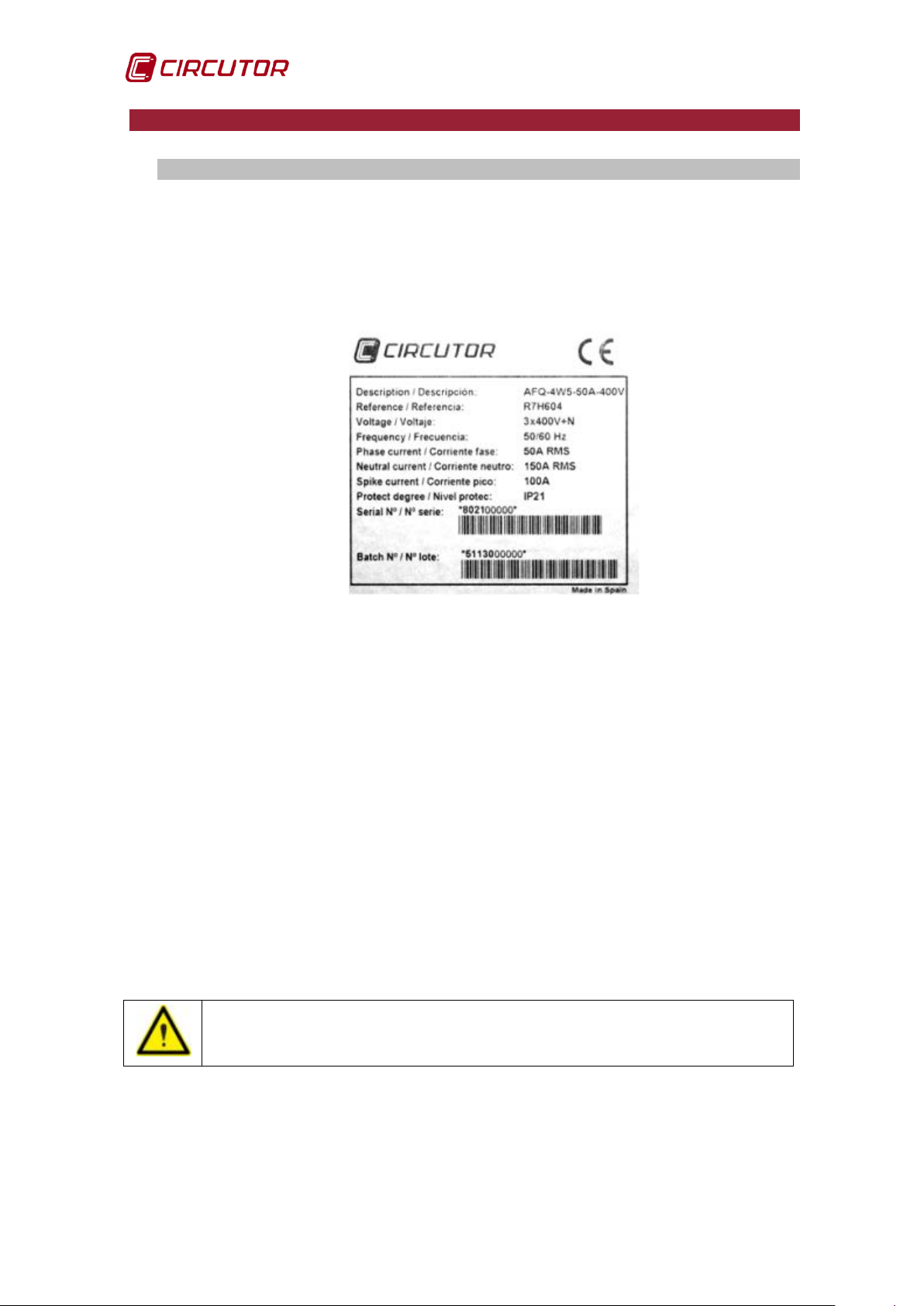
• Check that the unit received matches that described in your order and
that its electrical features are suitable for the mains where it is to be
connected. See features label on the rear of the door.
(Figure 1)
Figure 1: Features label of the AFQ-4W
• Make sure that it is equipped with the following accessories:
- Main switch handle.
- 2 keys for locking the door.
- Manual.
The AFQ-4W-25 also has:
- 4 DIN 580-M8 suspension eye bolts (male).
- 4 DIN 963, M8x16 screws.
• Check the shipping documentation. The dispatch note number must
coincide with the number marked on the outer part of the unit. Unload and
transport the unit following the instructions in section 1.2.- TRANSPORT
AND HANDLING
Inspect the unit externally and internally before connecting.
• Check that all the unit's items on the packing list are present.
transport company and/or CIRCUTOR's after-sales service.
8 Instruction Manual
Page 9
AFQ-4W
If the unit is not to be immediately installed, it must be stored at a
the storage conditions listed in
In such a case, the unit should be kept in its original protective
1.2.- TRANSPORT AND HANDLING
The transport, loading and unloading and handling of the unit must
be carried out with proper precautions and using the proper manual
or mechanical tools to prevent damage to the unit.
location with a firm and level floor, and
the section must be observed. 1.3.- STORAGE
packaging.
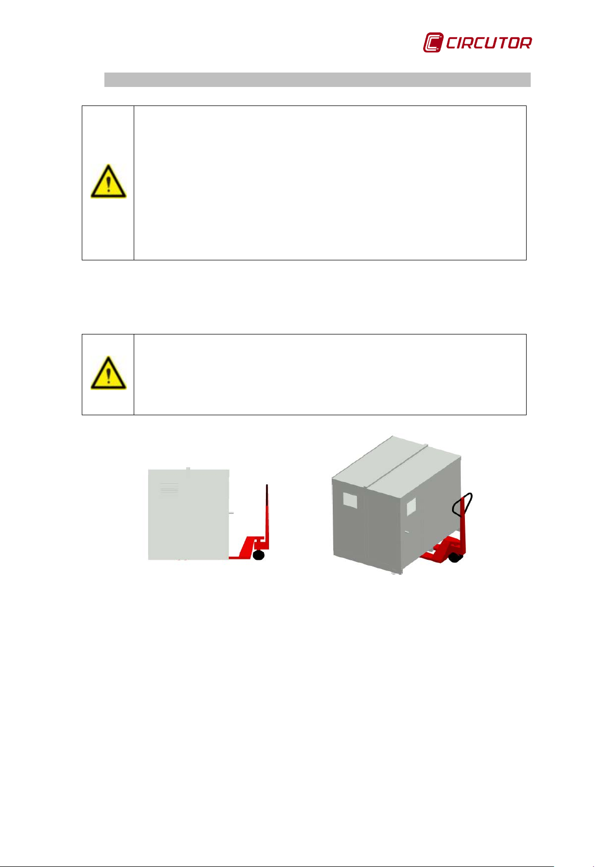
To move the unit a short distance, the unit's floor support profiles facilitate
handling with a pallet jack or forklift. (Figure 2)
The centre of gravity of some units may be found at a considerable
height. Therefore, when handling with a forklift, it is recommended
that the unit be securely fastened and that no abrupt operations are
made. The unit should not be lifted more than 20 cm off the ground.
Figure 2: Transport with pallet jack
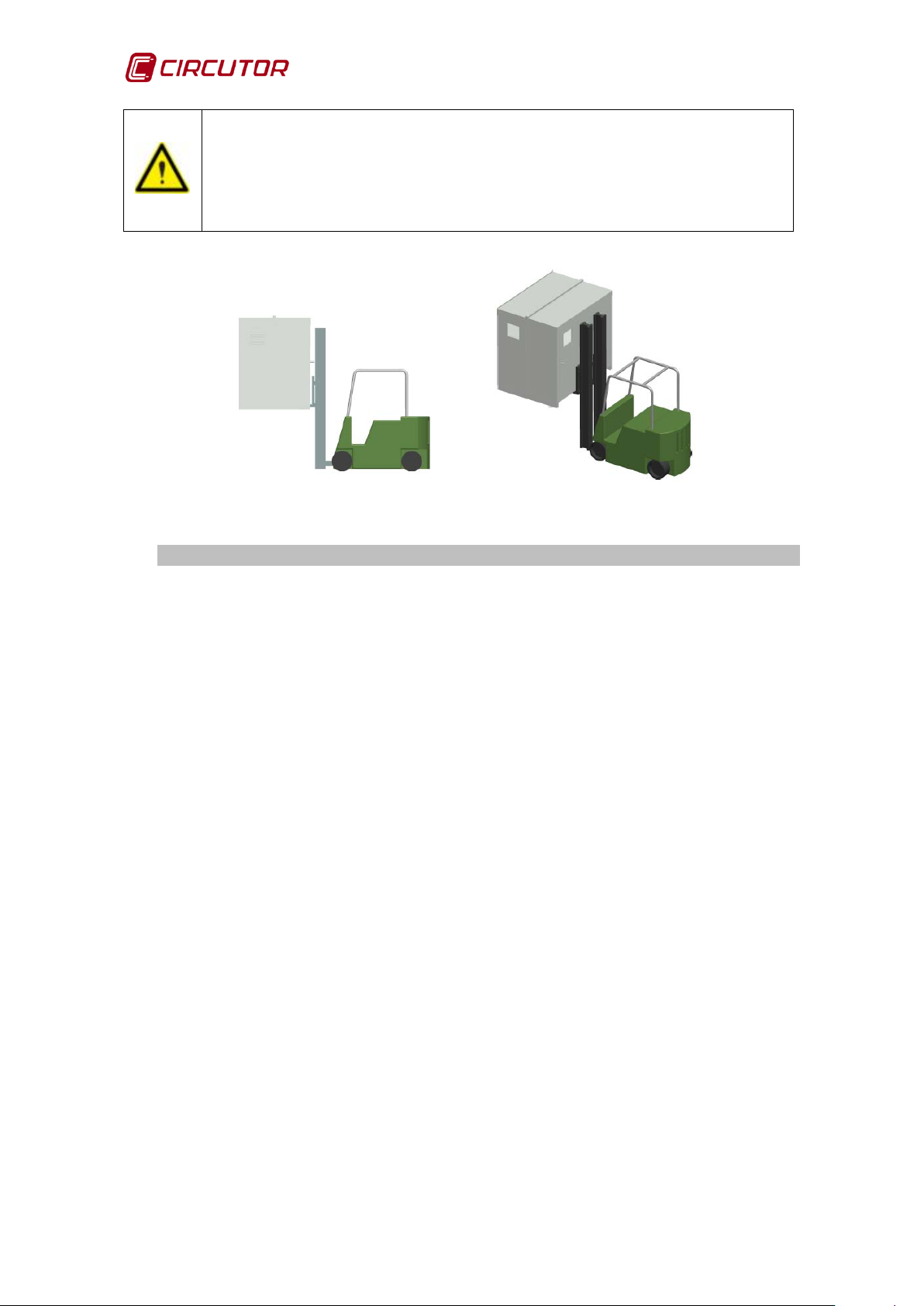
When unloading and moving the unit, use a forklift with forks long enough to
support the entire length of the base. Otherwise, the forks should be long
enough to support at least ¾ of said depth. The forks must be flat and supported
firmly by the base. The cabinet must be raised by placing the forks underneath
the profile that supports the unit. (Figure 3).
Instruction Manual 9
Page 10
AFQ-4W
There might be an offset in the centre of gravity from the centre of
the cabinet, as a result of the uneven distribution of loads in
equipment. The necessary precautions must be taken to prevent the
equipment from tipping over during abrupt operations.
Figure 3: Unloading with a forklift
1.3.- STORAGE
The unit should be stored according to the following recommendations:
• Avoid placing it on uneven surfaces.
• Do not store in outdoor areas, humid areas or areas exposed to the
splashing of water.
• Avoid hot spots (maximum environmental temperature: 45ºC)
• Avoid saline and corrosive environments.
• Avoid storing the unit in areas where a lot of dust is generated or where
the risk of contamination by chemical agents or other types of pollution is
present.
• Do not place any weight on top of the unit's cabinets.
10 Instruction Manual
Page 11
AFQ-4W
Models
AFQ-4W-25
AFQ-4W-50
AFQ-4W-100
AFQ-4W-150
AFQ-4W-200
Harmonic phase
current
Harmonic neutral
current
Harmonic peak
current
2.- PRODUCT DESCRIPTION
The AFQ-4W parallel multi-function active filters enable the following functions to
be performed:
Reduction of harmonic currents up to order 50 (2500 Hz).
Correcting unbalanced current consumption in each phase of the
electrical installation.
Reactive power compensation. Both inductive and capacitive currents.
CIRCUTOR has 5 different fil ter mo dels :
25A
75A
50A
50A
RMS
150A
RMS
100A
PEAK
100A
RMS
300A
RMS
200A
PEAK
Table 1: A FQ-4W models
All active filter models have the followi ng :
An LCD 5.7" touch display.
An RS-485 connection.
150A
RMS
450A
RMS
300A
PEAK
200A
RMS
600A
RMS
400A
PEAK
RMS
RMS
PEAK
Instruction Manual 11
Page 12

AFQ-4W
2.1. AFQ-4W-25
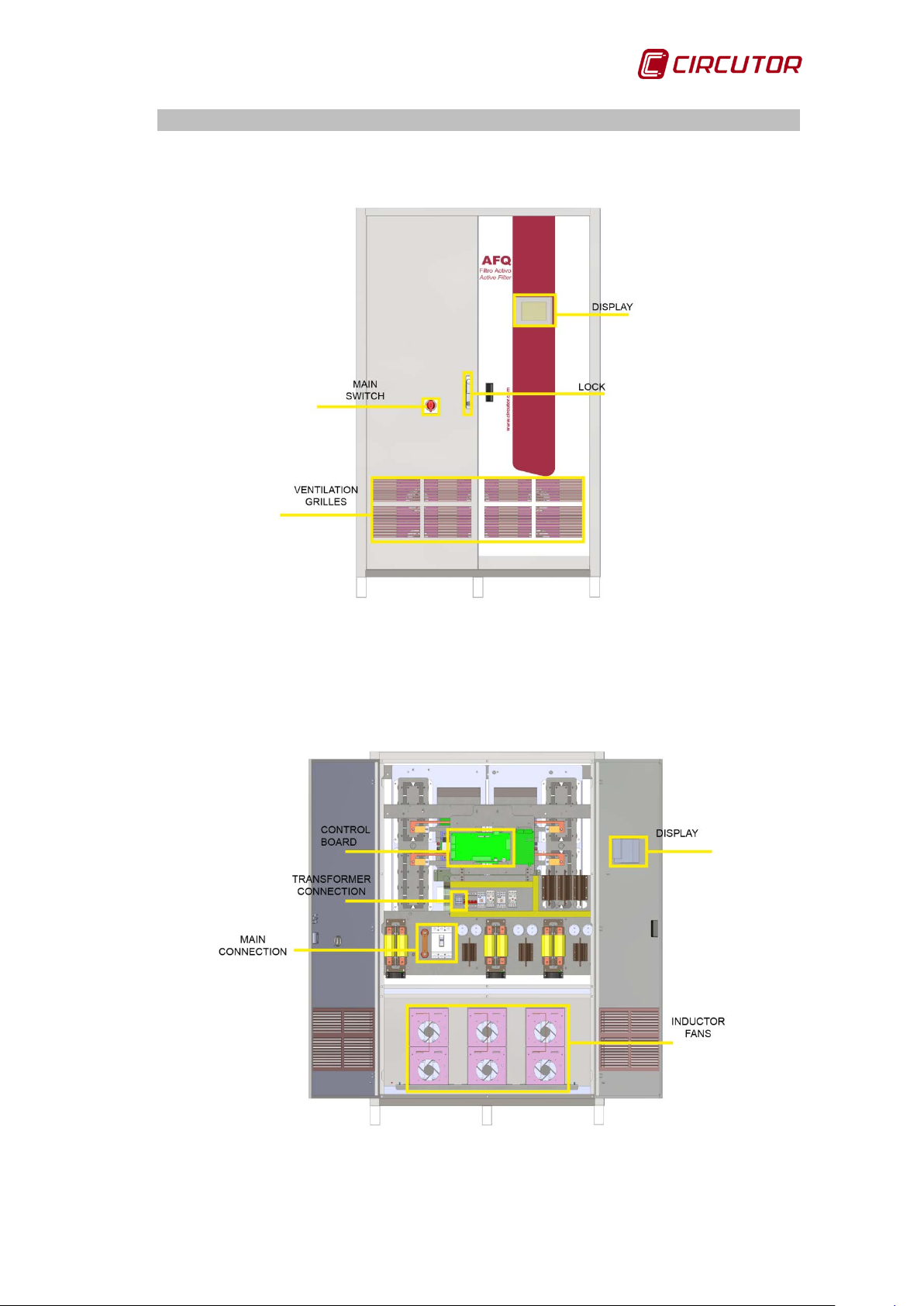
AFQ-4W-25 components seen from the front (Figure 4):
Figure 4: AFQ-4W-25 front view.
AFQ-4W-25 internal components (Figure 5):
Figure 5: AFQ-4W-25 inte rio r.
12 Instruction Manual
Page 13

AFQ-4W
2.2. AFQ-4W-50
AFQ-4W-50 components seen from the front (Figure 6):
Figure 6: AFQ-4W-50 front view.
AFQ-4W-50 internal components (Figure 7):
Figure 7: AFQ-4W-50 inte rio r.
Instruction Manual 13
Page 14

AFQ-4W
2.3. AFQ-4W-100
AFQ-4W-100 components seen from the front (Figure 8):
Figure 8: AFQ-4W-100 front view.
AFQ-4W-100 internal components (Figure 9):
Figure 9: AFQ-4W-100 interior.
14 Instruction Manual
Page 15
AFQ-4W
2.4. AFQ-4W-150 and AFQ-4W-200
AFQ-4W-150 and AFQ-4W-200 componen ts seen from the front (Figure 10):
Figure 10: A FQ-4W-150 and AFQ-4W-200 front view.
AFQ-4W-100 and AFQ-4W-200 internal components
(Figure 11):
Figure 11: AFQ-4W-150 and AFQ-4W-200 interior.
Instruction Manual 15
Page 16
AFQ-4W
st only
In order to use the unit safely, it is critical that individuals who
Incorrect installation or configuration of the unit could cause serious
. Before starting any
maintenance, wait 5 minutes and check that there is no residual
Make sure the unit is properly earthed before powering up. Any
fault in the earth connection might cause a risk of electrocution to
the user and damage to the unit itself in the case of lightning or
, make sure the
secondary is short circuited. Never open a current transformer
3. UNIT INSTALLATION
3.1.- PRELIMINARY RECOMMENDATIONS
The unit installation and the maintenance operations mu
be carried out by authorised and qualified personnel.
handle it follow the safety measures set out in the standards of the
country where it is being used, use the necessary personal
protective equipment, and pay attention to the various warnings set
forth in this instruction man ual.
damage to the unit itself and to other devices of the installation.
Disconnect the main switch before starting any maintenance
task on the active filters.
The unit has DC and AC capacitors
voltage in the capacitors.
other transients.
Before operating on the current transformers
secondary under load.
16 Instruction Manual
Page 17
AFQ-4W
Never power or start up the active filter with the front door open or
Check the section 3.4.- SIZING THE NOMINAL CURRENT OF THE
to define the correct unit size. Failing to observe the
recommendations described in this section might cause the active
filter to work incorrectly and prevent proper compensation of the
Connect a reactor of at least 3% of the impedance on the input of
the side or rear covers removed.
Check that there is a neutral in the place where three-phase active filter
connections are made w i th neutral , AFQ-4W.
The active filter must be of the correct size for the harmonic currents it has to
filter and for the install ati on's el ectr i c al fe atures.
AFQ-4W
installation's current harmonics.
each of the loads.
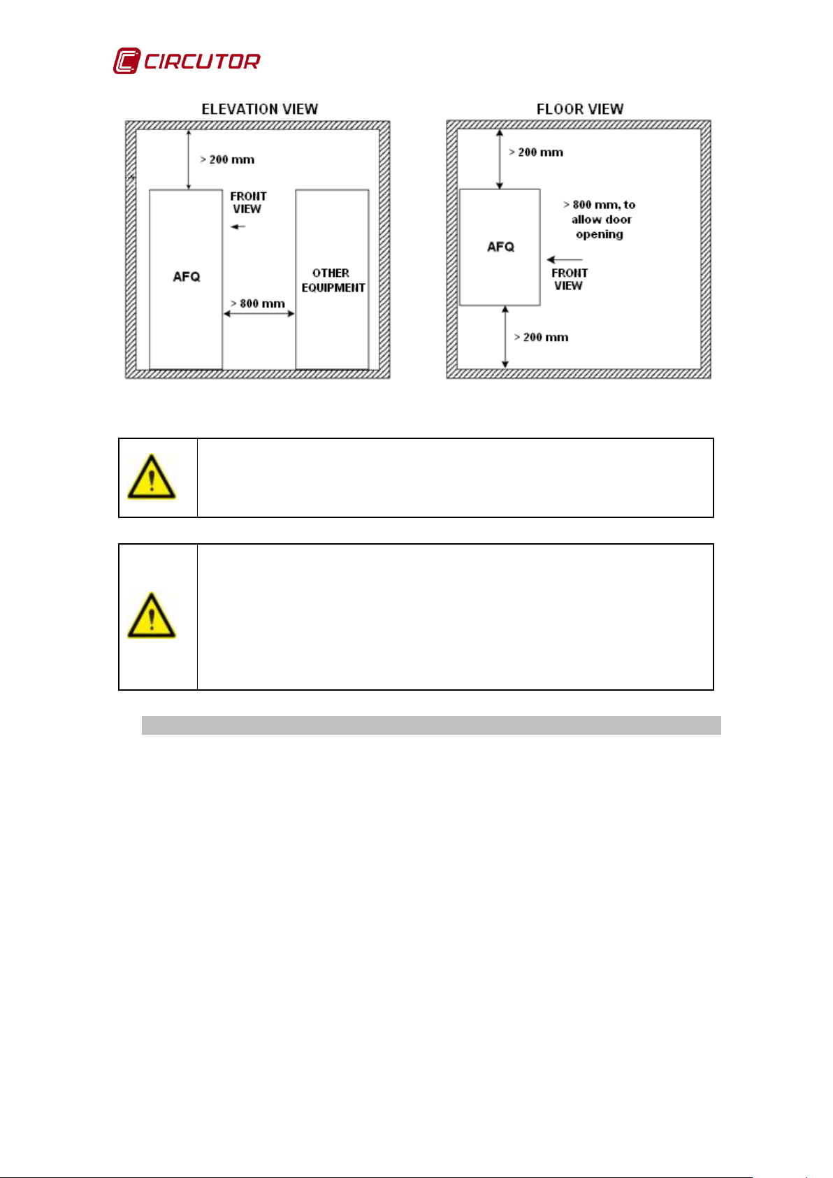
3.2.- INSTALLATION LOCATION
The unit must be installed in an environment where the temperature outside the
cabinet is between 0ºC and 40ºC, with a maximum humidity of 90% without
condensation.
Do not install the unit close to a hot spot and keep it out of direct sunlight.
Ventilation spaces must be left on the side and rear to allow for the use of fans.
There must also be sufficient space at the front of the cabinet to be able to open
the door if necessary (Figure 12):
200 mm on the sides of the cabinet.
200 mm between the top of the cabinet and the ceiling.
800 mm at the front of the cabinet.
Instruction Manual 17
Page 18
AFQ-4W
in a place protected from water, flammable
Make sure there are no reactive compensation units installed in the
. If there are any compensation units,
oid interference between them
Figure 12: Active filter spaces for ventilation.
Install the AFQ-4W
liquids, gases and corrosive substances.
same mains as the AFQ-4W
these must be untuned in order to av
and the AFQ-4W.
3.3.- STORAGE FOR LONG PERIODS
If the unit is not installed after receipt, the following recommendations must be
observed to keep the unit in a good state:
Keep the unit in a dry atmosphere and at a temperature of between 0ºC
and 50ºC.
Avoid exposure to direct sunlight.
Keep the unit in its original packaging.
If the active filter is stored for a long time disconnected from the mains, a
process must be applied to restore the internal dielectric layers of the DC bus
capacitors. Table 2 shows the recommendations for starting the unit depending
on the length of its storage period.
18 Instruction Manual
Page 19

AFQ-4W
Storage time
Process
< 1 year
No special treatment required.
Connect the AFQ-4W to the mains at least one
Connect the AFQ-4W to the mains at least one
1-2 years
> 2 years
hour before starting up the unit.
hour before starting up the unit. Restrict the
maximum load current to 5 mA.
Table 2: Start-up process depending on storage time.
3.4.- SIZING THE NOMINAL CURRENT OF THE AFQ-4W
The purchased active filter must be sized for the harmonic currents it has to filter.
The nominal current of the AFQ-4W must be at least 20% higher than the
maximum level of harmonics to be filtered. This factor may be higher depending
on the installation features.
The active filters can suffer from overloading when trying to cancel the harmonic
currents in high-impedance, short-circuit mains. The clearest symptom for
detecting such cases is that they originally start from a THD(V) (under voltage)
of over 3%. It has been seen that the higher the initial THD(V), the greater the
chance of filter overload.
The reason for this behaviour is that the load does not behave as a current
source, but rather the larger the harmonic current absorbed by the filter the more
harmonics are produced by the load, which can produce up to more than double
what was initially measured.
To avoid this phenomenon, it is best to oversize the active filter by multiplying the
initial current of harmonics measured in the load by a safety factor (SFh). In
other words:
I
(AFQ) = [SFh · I
filter
Where:
I
SF
I
THD(I): load current harmonic distortion
(AFQ): nominal current of the active filter
filter
: safety factor > 1.2.
h
: load maximum current
load
Equation 1: AFQ-4W nominal current
· THD(I) ]
load
To calculate this safety factor you must first know the parameter called shortcircuit ratio RSC at the connection point of the PCL transducers (not on the
installation input). The short -circuit ratio is defined as the ratio between the shortcircuit current of a mains (ISC) and the nominal current of the set of non-linear
transducers (I
) producing the harmonics to be filtered. (Equation 2)
NLC
Instruction Manual 19
Page 20

AFQ-4W
CNL
SC
SC
I
I
R =
Equation 2: Calculating the shor t-circuit ratio RSC.
In a real installation, the short-circuit current (ISC) in the PCL can be assessed by
having the voltage at the said point for two different load currents. For example,
full load, IA and 10% load, IB. If VOC is the rated voltage in a vacuum, the ISC, can
be calculated using the formula shown in Figure 13:
Figure 13: Graphic for calcula ting I
Figure 14 The safety factor (SF
Figure 14: Approximate graphic for calculating the SFh.
.
SC
) can be obtained from the graphic in:
h
20 Instruction Manual
Page 21
AFQ-4W
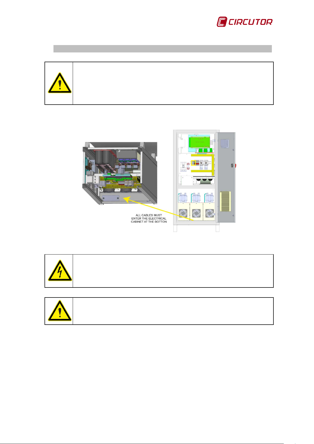
All power and current reading cables must enter the electrical cabinet
guaranteeing the IP and the user
Perform the drilling and/or milling out of the area for this
,
cabinet to
3.5.- CONNECTIONS
by the cover on the bottom,
protection against the parts of the cabinet with high voltages
( Figure 18).
Figure 15: Cable entry from the bottom of the electrical cabinet.
(Figura 15) puts at risk the integrity of the equipment and users
as well as the loss of the warranty.
Drilling the cover cable entry out of the electrical
avoid drilling debris may affect the functioring of the AFQ.
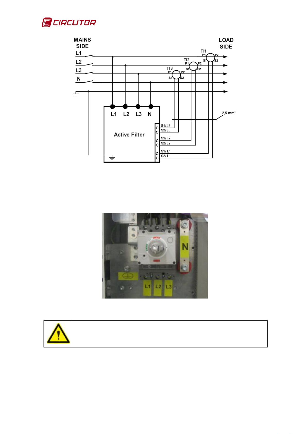
The connection diagram in Figure 16 must be used when performing the
electrical connections in the electrical cabinet:
Instruction Manual 21
Page 22
AFQ-4W
Figure 16: Connection diagr am of the AFQ-4W.
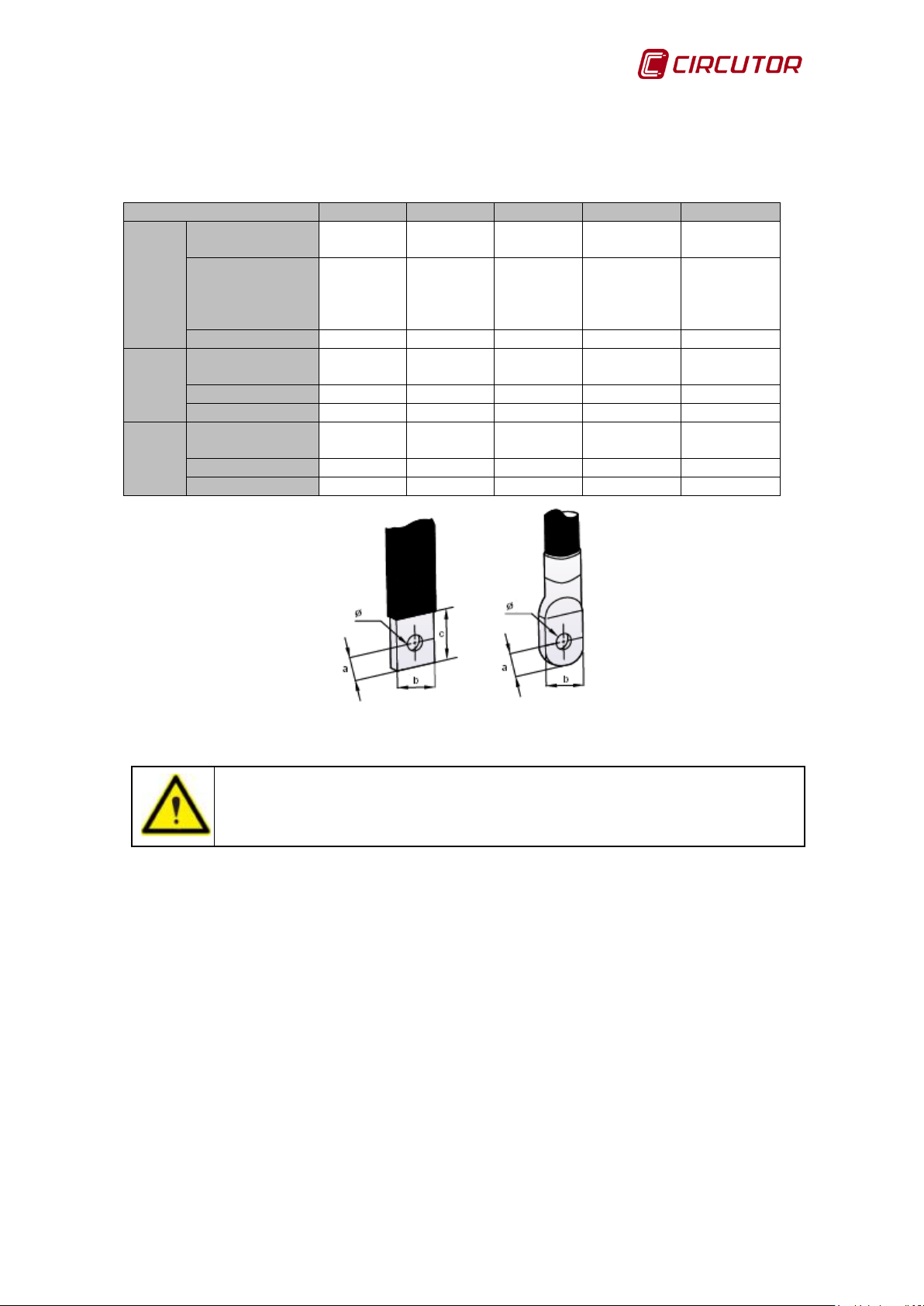
3.5.1. THREE-PHASE MAINS TO NEUTRAL CONNECTION
The connections of the three-phase mains to neutral (L1, L2, L3, N and Earth)
are identified in the active filter as in Figure 17.
Figure 17: Mains connection points in the AFQ-4W.
Use cables of a cross-section suitable for the filter nominal current.
22 Instruction Manual
Page 23
AFQ-4W
AFQ-4W
25A
50A
100A
150A
200A
Cross-section
(mm2)
a ≤ 10
Ø > 8
a ≤ 10
Ø > 8
a ≤ 10
Ø > 8
a ≤ 10
Ø > 8
a ≤ 10
Ø > 8
Torque (Nm)
7.6
7.6
7.6
14.4
14.4
Cross-section
(mm2)
Terminal (mm)
Ø > 8
Ø > 10
Ø > 10
Ø > 10
Ø > 10
Torque (Nm)
12
20
25
30
30
Cross-section
(mm2)
Terminal (mm)
Ø > 8
Ø > 8
Ø > 10
Ø > 10
Ø > 10
Torque (Nm)
12
20
25
30
30
to avoid the risk of
The minimum cable cross-section will depend on the filter range (Table 3).
L1
L2
L3
N
Earth
Terminal (mm)
10 16 35 70 95
b ≤ 20
c ≤ 21
25 50 95 2x95 2x95
25 50 95 95 95
b ≤ 20
c ≤ 21
b ≤ 20
c ≤ 21
b ≤ 20
c ≤ 21
b ≤ 20
c ≤ 21
Table 3: Minimum cross-sectio n o f input cables connected to the AFQ-4W.
Make sure that the AFQ-4W is correctly earthed
electrical discharge.
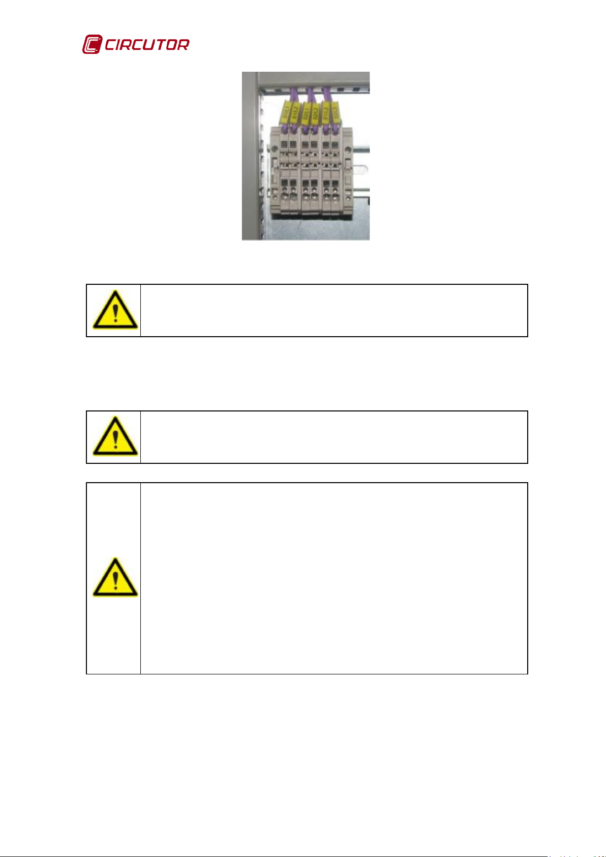
3.5.2. CURRENT TRANSFORMER CONNECTION
Current transformers TI1, TI2 and TI3, are located on the load side (downstream
of the filter) and are used for measurement and control purposes. In the active
filter, connections S1/L1, S1/L2, S1/L3 S2/L1, S2/L2, S2/L3 have to be made as
shown in Figure 18.
Instruction Manual 23
Page 24
AFQ-4W
The use of transformers with ratios close to the current to be
Current transformers TI1, TI2, TI3 must be correctly connected for the
filters to work properly. If the phases L1, L2 and L3 are
ase 1 and the transformer output cables are
measures phase 2 and the transformer output cables are
3 and the transformer output cables are
Figure 18: Transformer connection points in th e AFQ-4W.
Class 0.2S transformers of the CT or TCH series are recommended.
The use of class 0.2, 0.5s or 0.5 transformers will slightly jeopardise the
behaviour of the active filter although they always provide acceptable harmonic
filtering replies.
measured is recommended.
AFQ-4W
switched in the secondary, the filter will not work properly.
Check the connections and make sure that:
TI1 measures ph
connected in posts S1/L1 and S2/ L1 of the filter cabinet.
TI2
connected in posts S1/L2 and S2/ L2 of the filter cabinet.
TI3 measures phase
connected in posts S1/L3 and S2/ L3 of the filter cabinet.
24 Instruction Manual
Page 25

AFQ-4W
All of the active filters connected in parallel must have exactly the
MAINS side
LOAD side
AFQ-4W
AFQ-4W
AFQ-4W
3.6.- PARALLEL CONNECTION OF 2 TO 8 ACTIVE FILTERS
You can connect up to 8 active filters by connecting the three phases plus the
neutral in parallel. The load current measurement connects in series so that all of
the filters are using the same measuring transformers on the load. (Figure 19)
Figure 19: Parallel connection of 2 to 8 filters.
Section 4.3.3. explains how to configure the active filter to work with different
active filters in parallel.
same configuration in the WORK MODE and PARAMETERS. Refer
to section
4.3.- CONFIGURATION
Instruction Manual 25
Page 26
AFQ-4W
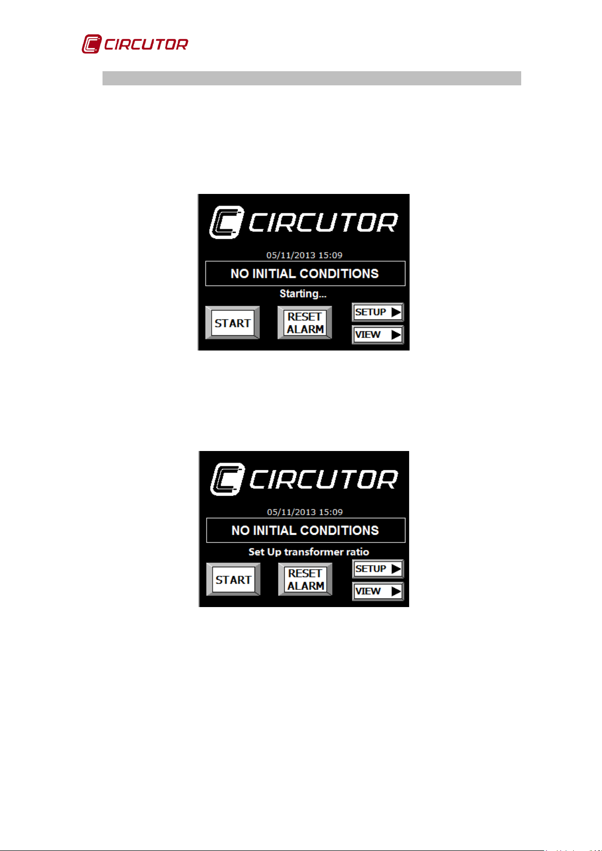
3.7.- CONNECTING THE FILTER TO THE MAINS
Once the connections specified in the above sections have been checked, the
main switch of the active filter will be switched on. When the unit is started, the
messages “NOT INITIAL CONDITIONS” and “Starting …” must appear on the
display ( Figure 20).
Figure 20: Start-up message of the AFQ-4W.
A few seconds later, the message “Set Up transformer ratio” will appear
(Figure 21).
Figure 21: Home screen displayed du ring the AFQ-4W's start-up.
Another message may appear if there is some problem in the filter connections
or the power supply. The section APPENDIX A: DISPLAY MESSAGES of this
manual describes all of the causes of malfunction and their corrective measures.
26 Instruction Manual
Page 27

AFQ-4W
, carefully follow the steps given in
If the transformer ratio is not that of the transformer installed, the
3.8.- FILTER START-UP
Finally, start-up the AFQ-4W. To consult all of the configuration parameters in
detail, see 4.3.- CONFIGURATION of this manual .
Before starting up the AFQ-4W
Configuration 3.8.1 and Verification of the unit 3.8.2.
3.8.1- CONFIGURATION
3.8.1.1.- CONFIGURATION OF THE CURRENT TRANSFORMER
Access the parameter configuration screen by pressing SETUP and select the
PARAMETERS option (Figure 22):
Figure 22: Configuration of the transformer ratio and the number of modules in parallel.
Configure the TRANSFORMER RATIO parameter with the ratio between the
primary and secondary of the load current measurement transformer.
The AFQ-4W admits the following transformation ratios: 5/5, 10/5, 15/5, 20/5,
25/5, 30/5, 40/5, 50/5, 60/5, 75/5, 100/5, 125/5, 150/5, 200/5, 250/5, 300/5,
400/5, 500/5, 600/5, 700/5, 750/5, 800/5, 1000/5, 1200/5, 1500/5, 1600/5,
2000/5, 2500/5, 3000/5, 4000/5 and 5000/5.
AFQ-4W will not work properly.
Instruction Manual 27
Page 28

AFQ-4W
An incorrect configuration may significantly affect the performance of
personnel to select
3.8.1.2.- PARALLEL MODULE CONFIGURATION
Configure the number of units in parallel in the PARALLEL MODULES
parameter (Figure 22). If there is a single unit in parallel, leave the default value
(1).
3.8.1.3.- WORK MODE CONFIGURATION
In order to configure the work mode, return to the home screen, press START
and access the work mode configuration screen.
Start the harmonic filtering, phase balancing and/or reactive compensation
functions depending on the needs of the installation (Figure 23). (For further
information on all of the functi ons, refer to section 4.3.- CONFIGURATION )
Figure 23: Configuration of the functions of the AFQ-4W.
the AFQ-4W. Consult the technician or qualified
the unit configuration, depending on the needs of the installation.
28 Instruction Manual
Page 29
AFQ-4W
3.8.2- UNIT VERIFICATION
3.8.2.1.- VERIFICATION O F THE MAINS VOLTAGE AND FREQUENCY
The voltage and current screen (Figure 24) can be accessed from the home
screen by pressing on VIEW:
Figure 24: Verify mains voltages, currents and frequency.
Make sure the mains voltage measurements correspond to the real
voltages of the installation.
Make sure the frequency measured by the AFQ-4W is the real frequency
of the installation.
Make sure the load current measurements correspond to the installation
current levels.
Instruction Manual 29
Page 30
AFQ-4W
3.8.2.2.- VERIFICATION OF THE ACTIVE AND REACTIVE POWER
The load power screen (Figure 25) can be accessed from the home screen by
pressing VIEW:
Figure 25: Verify active and reactive power and load power factor readings.
Make sure the active power measurement of the load equals the power
levels of the installation.
Make sure the reactive power measurement of the mains equals the
reactive power levels of the installation.
Check the power fact or in the three phases. If there are phases with very
high reactive power and very low active power levels, this might indicate
an error in the phase order. In this case, check the connections of the
three-phase mains power supply cables with neutral and the load current
reading cables, as described in sections 3.5.1 and 3.5.2.
30 Instruction Manual
Page 31

AFQ-4W
3.8.3- ACTIVE FILTER START-UP
Having checked the active and reactive power and power factor of the
installation, you can return to the main screen to start up the AFQ-4W.
If there is no problem with the connections, the home screen should show the
message “STOP” (Figure 26).
Figure 26: Message displayed when the unit is ready for start-up.
By pressing START, the active filter will take action to neutralise the harmonics,
balance the phases and/or compensate reactive power.
If it has started up correctly, the screen will show the message “RUN”
(Figure 27).
Figure 27: Message displayed when the unit is running.
If there is any problem in the connections of the filter or in the configuration, the
“NOT INITIAL CONDITIONS” message will be shown along with a description of
the malfunction (Figure 28).
Instruction Manual 31
Page 32

AFQ-4W
Figure 28: Message displayed when the unit is not ready for start-up.
The APPENDIX A: DISPLAY MESSAGES of this manual contains all of the causes
of malfunction and their corrective measures.
If an alarm is tripped, the “ALARM” message will be shown along with a
description of the problem (Figure 29).
Figure 29: Message displayed when the unit is in an alarm state.
Refer to section APPENDIX A: DISPLAY MESSAGES to see the causes of the
alarm and to be able to apply the corrective measures.
The RESET ALARM button rearms the unit if the cause of the alarm has
disappeared or been solved.
32 Instruction Manual
Page 33

AFQ-4W
Mains frequency
Fundamental: 50 Hz
Fundamental: 60 Hz
3
150 Hz
180 Hz
5
250 Hz
300 Hz
7
350 Hz
420 Hz
4. OPERATION
4.1.- OPERATING PRINCIPLE
4.1.1.- HARMONICS
Non-linear loads such as: rectifiers, inverters, speed drives, ovens, etc, absorb
periodic non sine-wave currents from the mains.
These currents are composed of a fundamental frequency component, rated at
50 or 60 Hz, plus a series of overlapping currents, with frequencies that are
multiples of the fundamental frequency; they are defined as HARMONICS.
Figure 30: Distorted wave shape decomposition.
The result is a deformation of the current and, as a result, of the voltage, causing
a series of associated side effects. These can be machinery overload, electric
cable heating, circuit breaker disconnection, damage to sensitive units, etc.
Order (n)
Table 4: Frequ ency of each harmonic.
4.1.2.- BASIC CONCEPTS
It is best to define some terms related to harmonics, fundamental for interpreting
any measurement and study:
Instruction Manual 33
Fundamental frequency (
Order of a harmonic (n)
: Original wave frequency (50/60 Hz ) .
f
)
1
: A whole number given by the ratio between the
frequency of a harmonic and the fundamental frequency. The order
determines the frequency of the harmonic (E.g.: 5th harmonic → 5•50 Hz =
250 Hz).
Page 34

AFQ-4W
Fundamental compo n e nt (
U
: A sine wave component of order 1 of the
I
o
)
1
1
Fourier frequency serial development equal to the original periodic wave.
Harmonic component (
U
n
: A sine wave component of order over 1 of
I
o
)
n
the Fourier frequency serial development a whole multiple of the original
frequency.
Individual distortion rate (
U
% o
n
: A ratio in % between the RMS value
I
%)
n
of the voltage or harmonic current (Un o In) and the RMS value of the
fundamental component (U1 o I1).
Equation 3: Individual distortion rate
True root mean square value (TRMS)
: The square root of the sum of the
squares of all components forming the wave.
Harmonic content
Equation 4: True root mean square value
: The difference between the total voltage or current and
the corresponding fundamental v al ue.
Harmonic distortion r ate (THD)
: The ratio between the RMS value of the
harmonic content of the voltage and/or current and the value of the
fundamental component.
Equation 5: Harmonic distortion rate.
34 Instruction Manual
Page 35

AFQ-4W
Type of load
Wave shape
Harmonic spectrum THD(I)
6-pulse transducers:
4.1.3.- MOST COMMON HARMONICS
Table 5
lists the most common harmonic generator loads and the wave shape of
the current they consume, as well as their harmonic spectrum.
- Speed drives
- UPS
- Three-phase rectifiers
- Transducers for
electrolysis and baths
- Discharge lamps
- Single-phase transducers
- Lighting lines
- Computer lines
-
Sound and image units
Table 5: Most common harmonics.
4.1.4.- HARMONIC COMPENSATION
Active filters are units responsible for the compensation o f harm oni c c ur r ents.
Compensation is achieved by injecting harmonic currents equal to those in the
installation in counter phase.
This means that upstream of the filter connection point, the signal shows virtually no
harmonic distortion. (Figure 31).
Instruction Manual 35
Figure 31: General connection d iagram of an active filter
Page 36
AFQ-4W
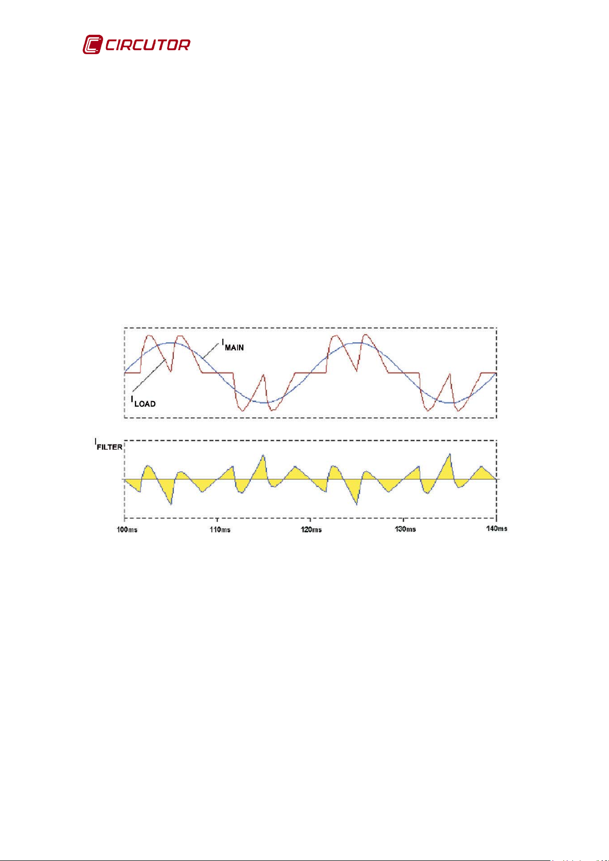
4.1.5.- OPERATING PRINCIPLE
Active filters are based on the following principle:
I
FILTER
Equation 6: Operating principle
=
I
MAIN
-
I
LOAD
In other words, they detect the difference between the required current sine
wave (I
the difference between both waves (I
) and the signal deformed by the harmonics (I
MAIN
).
FILTER
). And they inject
LOAD
Figure 32 show the wave shapes of the currents injected by the active filters.
These show the required wave, the existing deformed wave and the filter current
(I
FILTER).
Figure 32: Current in the load, in the filter and in the mains.
36 Instruction Manual
Page 37

AFQ-4W
4.2.- DISPLAY
The active filter has a touch display with different screens used for display and
configuration purposes.
4.2.1.- MAIN SCREEN
The main screen contains information regarding the filter status, the start and
stop controls, the alarm rearm process and the accesses to the configuration
and display variables .
Figure 33: Main screen.
As we can see in Figure 33 we can distinguish the following parts:
1- START/STOP key: The start and stop active filter key. The AFQ-4W must
be "STOPPED" before it is started.
2- RESET ALARM key: Alarm rearm key. If the cause of the alarm has not
been resolved, this key allows us to restart the unit.
3- VIEW key: Access to the display screens.
4- SETUP. key: Access to the configuration screens.
5- A message with additional AFQ-4W status information: The APPENDIX A:
DISPLAY MESSAGES
explains all of the messages that can appear along
with the filter status. This information is particularly useful for detecting
and resolving operational problems with the unit and for determining its
work conditions.
Instruction Manual 37
Page 38

AFQ-4W
Message
Status
NO CONNECTION
Initial state of the display .
NOT INITIAL CONDITIONS
AFQ-4W
STOP
The AFQ4W is stopped and ready to start.
RUN
The AFQ-4W is operating
ALARM
The AFQ-4W has a tripped alarm.
6- Message indicating the filter status (Table 6):
The
Table 6: Filter status messages.
initial start-up conditions are not met.
7- Date and time: Display of the unit date and time.
4.2.2.- DISPLAY SCREENS
On pressing VIEW in the home screen (Figure 33), you access the general
display (Figure 34), from where you can access all of the display screens.
Figure 34: General display screen.
The display screens are organised into 4 groups:
• Voltage and current: this option gives us access to the voltage and
current display screen.
• Power: Access to the power display screen.
• THD I: Access to the display screen of the total harmonic distortion of the
load and mains current.
• LOG: Access to the alarm log display screen.
Click on the MAIN key to open the home screen.
38 Instruction Manual
Page 39

AFQ-4W
4.2.2.1.- BROWSING DIAGRAM
Figure 35: Display screen browsing diagram.
Instruction Manual 39
Page 40

AFQ-4W
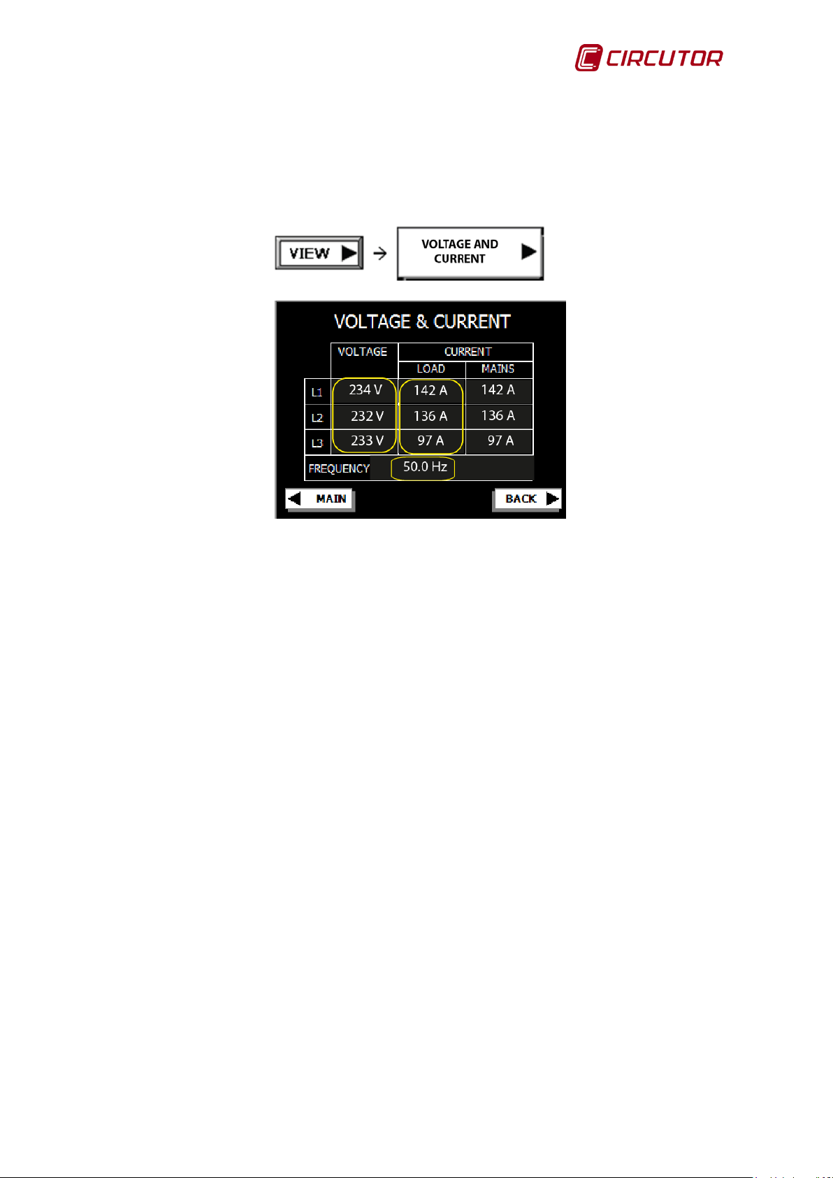
4.2.2.2.- Voltage and current display screen
This screen (Figure 36) gives the readings of the effective voltages of the three
phases, the effective load currents, the effective mains current and the mains
frequency.
Figure 36: Voltage and current display screen.
Click on the Main key to open the home screen.
Click on the Back key to return to the general display screen.
4.2.2.3.- General power screen
This screen (Figure 37) gives access to the power display screens.
Figure 37: General power screen.
Organised into 3 groups:
• Power Load: Access to the active and reactive and apparent power
display screens of the three load phases.
• Power Mains : Access to the active and reactive and apparent power
display screens of the three mains phases.
40 Instruction Manual
Page 41

AFQ-4W
• Power Filter: Access to the display screen of the percentage of the AFQ-
4W power used with respect to the nominal power of the three phases.
Click on the Main key to open the home screen.
Click on the Back key to return to the general display screen.
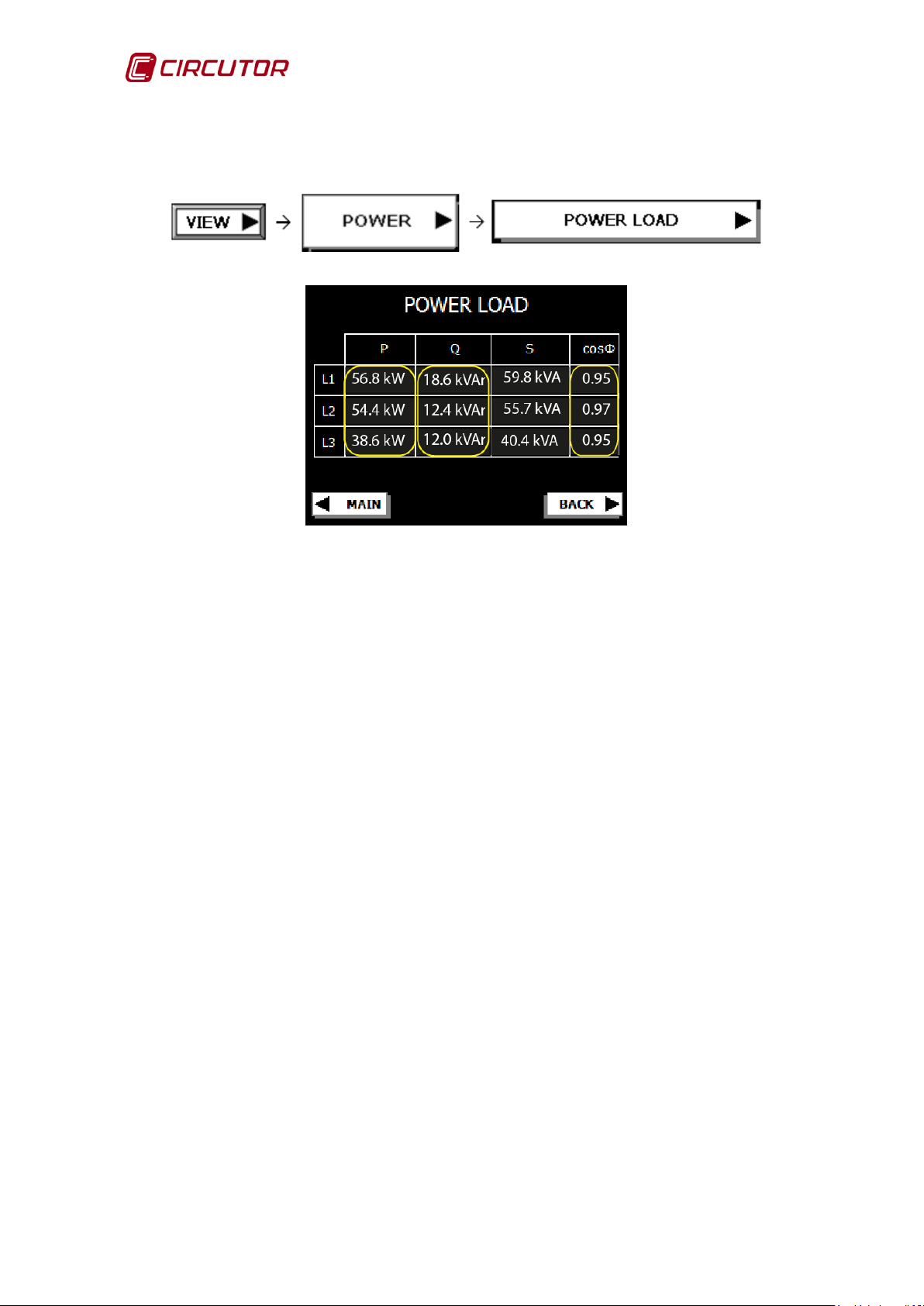
4.2.2.3.1.- Load power display screen
This screen (Figure 38) shows the active, reactive, apparent powers and the
power factor of the three load phases.
Figure 38: Load power display screen.
Click on the Main key to open the home screen.
Click on the Back key to return to the general power screen.
Instruction Manual 41
Page 42

AFQ-4W
4.2.2.3.2.- Mains power display screen
This screen (Figure 39) shows the active, reactive, apparent powers and the
power factor of the three mains phases.
Figure 39: Mains power display screen
Click on the Main key to open the home screen.
Click on the Back key to return to the general power screen.
4.2.2.3.3.- Filter power display screen
This shows the instant power used in the three phases L1, L2, L3 of the active
filter as a percentage w it h respect to the pro g r ammed power limit (Figure 40).
Figure 40: Filter power display screen
42 Instruction Manual
Page 43
AFQ-4W
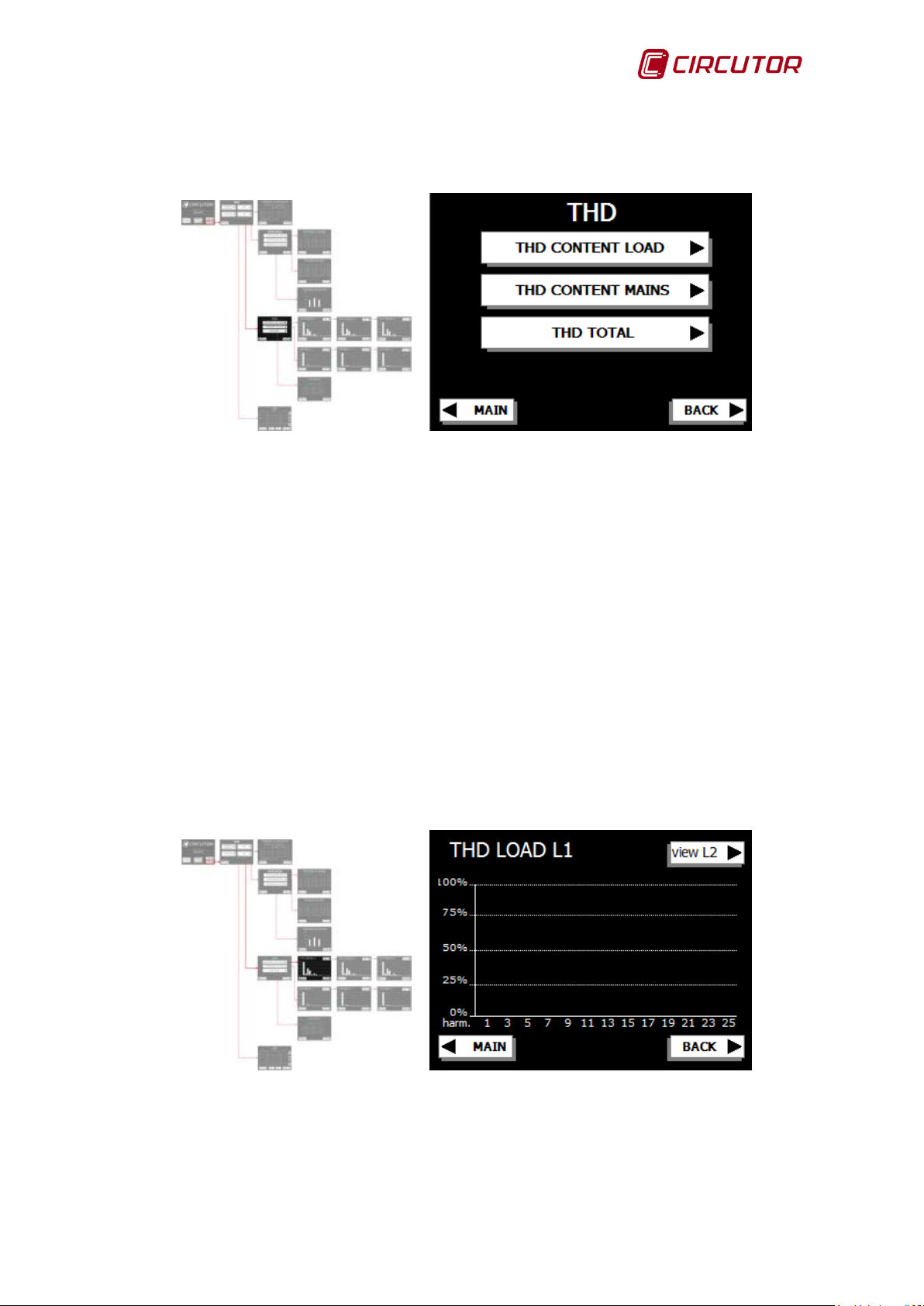
4.2.2.4.- General THD(I) screen
This screen (Figure 41) gives access to the different THD(I) display screens.
Figure 41: General THD(I) screen
• THD(I) Content Load: Access to the display screen of the spectrum in
load current frequencies.
• THD(I) Content mains : Access to the display screen of the spectrum in
mains current frequencies.
• THD(I) Total: Access to the display screen of the total mains and load
THD(I) for the three phases.
Click on the Main key to open the home screen.
Click on the Back key to return to the general display screen.
4.2.2.4.1.- THD Display screen of the phase 1 load current
This screen (Figure 42) will show the THD(I) of the phase 1 load.
Figure 42: THD Display screen of the phase 1 load current.
Click on the Main key to open the home screen.
Click on the Back key to return to the general THD(I) screen.
The view L2 key gives us access to the THD screen of the phase 2 load current.
Instruction Manual 43
Page 44
AFQ-4W
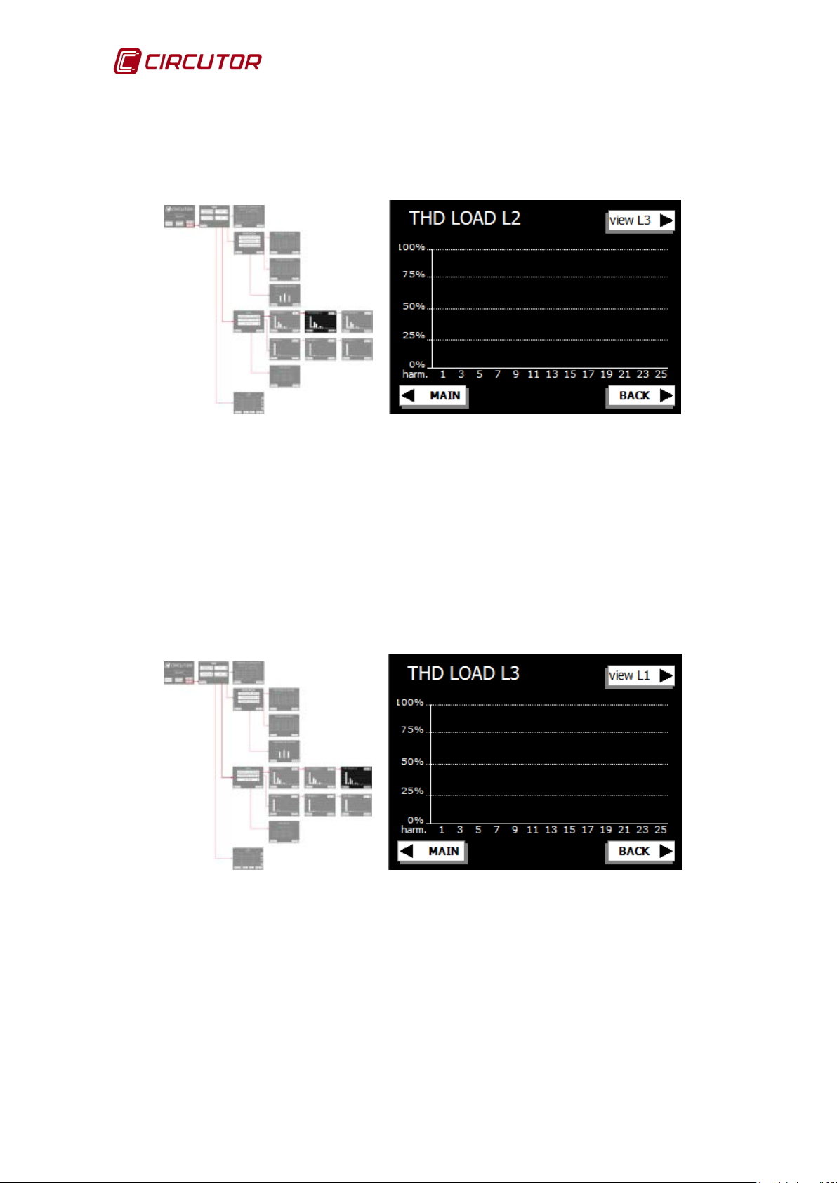
4.2.2.4.2.- THD Display screen of the phase 2 load current
This screen (Figure 43) will show the THD(I) of the phase 2 load.
Figure 43: THD Display screen of the phase 2 load current.
Click on the Main key to open the home screen.
Click on the Back key to return to the general THD(I) screen.
The view L3 key gives us access to the THD screen of the phase 3 load current.
4.2.2.4.3.- THD Display screen of the phase 3 load current
This screen (Figure 44) will show the THD(I) of the phase 3 load.
Figure44: THD Display screen of the phase 3 load current.
Click on the Main key to open the home screen.
Click on the Back key to return to the general THD(I) screen .
The view L1 key gives us access to the THD screen of the phase 1 load current.
44 Instruction Manual
Page 45

AFQ-4W
4.2.2.4.4.- THD Display screen of the phase 1 mains current
This screen (Figure 45) will show the THD(I) of the phase 1 mains.
Figure45: THD Display screen of the phase 1 mains current.
Click on the Main key to open the home screen.
Click on the Back key to return to the general THD(I) screen.
The view L2 key gives us access to the THD screen of the phase 2 mains
current.
4.2.2.4.5.- THD Display screen of the phase 2 mains current
This screen (Figure 46) will show the THD(I) of the phase 2 mains.
Figure 46: THD Display screen of the phase 2 mains current.
Click on the Main key to open the home screen.
Click on the Back key to return to the general THD(I) screen.
The view L3 key gives us access to the THD screen of the phase 3 mains
current.
Instruction Manual 45
Page 46

AFQ-4W
4.2.2.4.6.- THD Display screen of the phase 3 mains current
This screen (Figure 47) will show the THD(I) of the phase 3 mains.
Figure 47: THD Display screen of the phase 3 mains current.
Click on the Main key to open the home screen.
Click on the Back key to return to the general THD(I) screen.
The view L1 key gives us access to the THD screen of the phase 1 mains
current.
4.2.2.4.7.-Display screen of the total THD(I)
This screen (Figure 48) shows the reading of the total THD(I) of the mains and
load phases.
Figure 48: Display screen of the total THD(I).
Click on the Main key to open the home screen.
Click on the Back key to return to the general THD(I) screen.
46 Instruction Manual
Page 47

AFQ-4W
4.2.2.5.- Display screen of the alarm log
This screen (Figure 49) shows the log of events in the active filter, and indicates
the date and time when each event starts and ends.
Figure 49: Display screen of the alarm log.
Click on the Main key to open the home screen.
Click on the Back key to return to the general display screen.
Click on the CLEAR ALL key, all of the incidents are deleted.
Click on the CLEAR SELECT, the selected incident is deleted.
Click on the key to view the messages on the previous page.
Click on the key to view the messages on the following page.
Click on the key to view the messages on the above line.
Click on the key to view the messages on the following line.
Instruction Manual 47
Page 48

AFQ-4W
4.3.- CONFIGURATION
Press SETUP on the AFQ-4W home screen to open the setup menu.
Figure 50: General configuration screen.
The different sub-menus can be accessed through the initial configuration screen
(Figure 50):
• Operation mode, In this sub-menu, you can select the harmonic
neutralising, phase balancing and reactive current compensation options.
• Parameters, Contains the list of the measuring transformers, the
minimum current required to start up the AFQ-4W, the choice of the
control algorithm, the selection of the number of AFQ-4W in parallel and
the filter power limit.
• Filter data, Description of the technical features of the unit.
• Panel setup, Configuration of the language, date, time and
activation/deactivation of the screen sound.
Click on the Main key to open the home screen.
48 Instruction Manual
Page 49

AFQ-4W
4.3.1.- BROWSING DIAGRAM
Figure51: Configuration browsing diagram.
Instruction Manual 49
Page 50

AFQ-4W
4.3.2.- OPERATION MODE CONFIGURATION
In this menu (Figure 52), users can access different screens to perform the
following:
Figure 52: Work mode menu.
• Function selection: Activation or deactivation of the functions of the
AFQ-4W: harmonic filtering, reactive compensation and phase current
balancing.
• Selective filtering: Select the mains compensated harmonics.
• Enable Alarms: enable or disable the different alarms.
The password protection must be unlock ed to change all of these parameters .
Refer to section 4.3.6 to unlock the unit configuration.
Click on the Main key to open the home screen.
Click on the Back key to return to the general configuration screen.
50 Instruction Manual
Page 51

AFQ-4W
Function priority order
OFF
ON
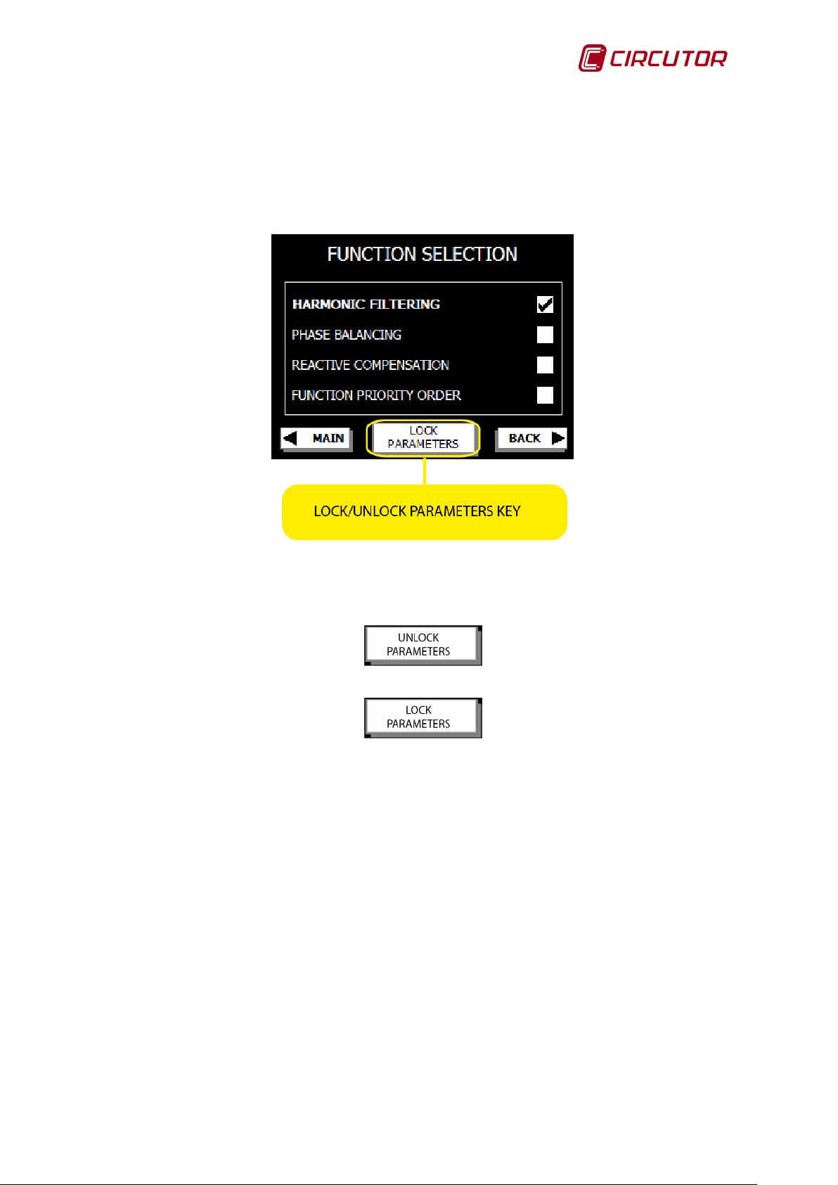
4.3.2.1.- FUNCTION SELECTION
Use this screen (Figure 53) to select the functions of the AFQ-4W:
Figure53: Function selection screen.
Harmonic filtering: Current harmonic neutralisation. (This option is enabled by
default.)
Phase balancing: Balancing of the current between phases. (This option is not
enabled by default.)
Reactive compensation: A function that allows the shifting of the cosΦ to be
compensated. (Thi s op t ion is not ena bl ed by default.)
Function priority Or der: The AFQ-4W allows the functions to be prioritised in
the event of filter current saturation by overload. When the “Function priority
order ” function is disabled, priority is given to the current harmonic filtering and
reactive compensation and overload balancing are penalised. If “Function
priority order” is activated, priority is given to current balancing between phases
and reactive current compensation, ahead of harmonic neutralisation. (This
option is not enabled by default.)
Click on the Main key to open the home screen.
Click on the Back key to return to the work mode screen.
Instruction Manual 51
Harmonic filtering
- +
PRIORITY
Table 7: Configuration of the order of priorities.
Phase balancing +
reactive compensation
Phase balancing +
reactive compensation
Harmonic filtering
Page 52
AFQ-4W
Click on the Lock/Unlock parameters key to lock or unlock the configuration
parameters. (Refer to section 4.3.6)
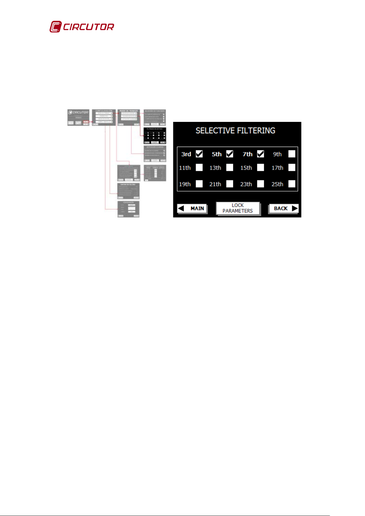
4.3.2.2.- SELECTIVE F ILTERING
Select the harmonics to be filtered on this screen (Figure 54):
Figure 54: Selective fil tering screen.
If the unit is configured with the control 1 algorit hm (Frequency mode)
(refer to section 4.3.3.- CONFIGURATION OF PARAMETERS , select the
harmonics you wish to neutralise from the 3rd to the 25th. (3rd, 5th, 7th by
default)
If the unit is configured with the control 2 algorithm (Tempora ry mode)
(refer to section 4.3.3.- CONFIG URATION OF PARAMETERS, you can (use
this option only if recommended by your supplier):
• Leave all harmonics unselected. The AFQ-4W will automatically
filter all harmonics from the 3rd to the 50th.
• Select the harmonics NOT to be filtered. The selected harmonics
will not be filtered.
Click on the Main key to open the home screen.
Click on the Back key to return to the work mode screen.
Click on the Lock/Unlock parameters key to lock or unlock the configuration
parameters. (Refer to section 4.3.6)
52 Instruction Manual
Page 53

AFQ-4W
Disable the polarity alarm only in installations with loads temporarily
by default and it is recommended not to
4.3.2.3.- ENABLE ALARM
This screen (Figure 55) allows us to control the different alarms:
Figure 55: Alarm activation screen.
Polarity alarm:
With the polarity alarm enabled, the active filter detects the direction of the load
measuring transformer current and if it detects inverse polarity (current towards
the mains) it returns to the initial conditions and restarts with the new conditions
in measuring the current. In the case of regenerative loads temporarily injecting
current into the mains, the polarity alarm will be activated.
With the polarity alarm disabled, if the load is injecting energy into the mains,
the AFQ-4W will measure negative active power and will stop neutralising
harmonics, balancing phases and compensating reactive energy. It will only
adjust the bus to the operating voltage.
When the active power is positive again, it will reperform all of the filtering
functions.
injecting current into the mains.
This option is enabled
disable it.
Before starting the active filter with the polarity alarm disabled, check
the connection and polarity of the load measuring transformers.
Instruction Manual 53
Page 54

AFQ-4W
by default and it is recommended not to
ed not to
Before disabling the resonance alarm, it is essential to make sure
there is no resonating current between the active filter and the load.
Resonating currents can damage the active filter and other devices
Low temperature Alarm:
This alarm is activated to prevent the unit from starting when the temperature
inside the active filter is below 0ºC or when there is a problem in the connections
of the temperature probes.
This option is enabled
disable it.
Resonance A larm:
The resonance alarm protects the unit against possible resonating currents
between the AFQ-4W and the load. This alarm is tripped when the level of a
harmonic in the load current rises considerably.
This option is enabled by default and it is recommend
disable it.
connected to the installation.
54 Instruction Manual
Page 55

AFQ-4W
4.3.3.- CONFIGURATION OF PARAMETERS
This menu (Figure 56) contains the parameters that have to be configured during
the installation of the active filter. To be modify these parameters, you have to
unlock the password (refer to 4.3.6.- PASSWORD) and have the filter in “STOP”
mode.
Figure 56: Parameter configuration screen.
Transformer ratio:
The ratio between the load transformer primary and secondary.
The active filter admits the following transformation ratios: 5/5, 10/5, 15/5, 20/5,
25/5, 30/5, 40/5, 50/5, 60/5, 75/5, 100/5, 125/5, 150/5, 200/5, 250/5, 300/5,
400/5, 500/5, 600/5, 700/5, 750/5, 800/5, 1000/5, 1200/5, 1500/5, 1600/5,
2000/5, 2500/5, 3000/5, 4000/5 and 5000/5.
Minimum current:
The minimum load current to start the active filter. The AFQ-4W will stop when
the load current is below the entered value and will start when it is higher.
Control algorithm:
Control algorithm selection:
1, Frequency mode: Harmonic filtering based on the selection of the
harmonics to be neutralised from the 3rd to the 25th. (Option enabled by
default.)
2, Temporary mode: Harmonic filtering based on the total and instant
neutralisation of the 3rd to 50t h har m onic s.
When the temporary mode is active, the AFQ-4W resets all the harmonics
selected in “Selective filtering” (Section 4.3.2.2) to completely neutralise
the harmonics.
Instruction Manual 55
Page 56

AFQ-4W
Do not use the Temporary mode (2) if the supplier has not
recommended this for their installation. This method can cause
All of the AFQ-4W must use the same load transformer. Refer to the
resonance in certain installations.
Power limit
This parameter allows the maximum power of the active filter to be limited. The
value is configured as a percentage with respect to the unit's nominal power. The
minimum configurable value is 20%, and the maximum is 100%.
Parallel Modules :
Access to the configuration screen of the number of active filters set out in
parallel with the same load (Figure 57).
Figure 57: Parallel module configuration screen.
A maximum of 8 AFQ-4W units can be installed in parallel, with different power
ratings.
section 3.6.- PARALLEL CONNECTION OF 2 TO 8 ACTIVE FILTERS
to install more than one active filter in parallel.
56 Instruction Manual
Page 57

AFQ-4W
4.3.4.- FILTER DATA This menu (Figure 58) contains the featur es of the AFQ-4W.
Figure 58: Filter data screen.
This information is factory set and cannot be changed by the user.
Filter range: AFQ-4W nominal current.
Serial number: Identification of the AFQ-4W.
Setup code: An internal code used to configure the unit.
Software version: Software version in the unit.
Panel version: Screen software version.
Click on the Main key to open the home screen.
Click on the Back key to return to the general configuration screen.
Instruction Manual 57
Page 58

AFQ-4W
4.3.5.- SCREEN CONFIGURATION
This screen (Figure 59) enables all of the screen parameters to be configured.
Figure 59: Screen configur ation.
Language: Panel language selection.
Date: .Date configuration.
Time: Time configuration.
Sound: Panel beep sound enabling and disabling.
Click on the Main key to open the home screen.
Click on the Back key to return to the general configuration screen.
58 Instruction Manual
Page 59
AFQ-4W
4.3.6.- PASSWORD
All configu ra tion opti ons of the active filter can be password protected. To lock or
unlock the configuration, press on the “LOCK/UNLOCK PARAMETERS” key on
the different screens (Figure 60)
Figure 60: Parameter locking key.
When the locking function is active, the unlocking option appears;
When the locking function is inactive, the activation option appears;
To activate or deactivate the parameter locking function, the password must be
entered on the virtual keyboard on the screen after pressing the
“LOCK/UNLOCK PARAMETERS” key. ( Figure 61)
Instruction Manual 59
Page 60

AFQ-4W
configuration, the password must be reactivated to
RS-485
connector
Figure 61 : Password screen.
The defaul t password is: 1 2 3 4.
The password is confirmed by pressing Enter.
Press ESC to return to the previous screen.
After changing the
avoid accidental changes in the future.
4.4.- RS-485 COMMUNICATIONS
The active filters have a RS-485 communications port with the MODBUS RTU
communications protocol.
The RS-485 communication cable is connected to the back of the display, as
shown in Figura 62:
Figure 62: Position of the RS-485 connector in the AFQ-4W
60 Instruction Manual
Page 61

AFQ-4W
Variable
Value
Protocol
MODBUS RTU slave
Peripheral no.
2
Baud Rate
9600
Parity
No
Data bits
8
Stop bits
1
Permitted Modbus functions
(1)
Read (R)
03
Write (W)
10
The RS-485 connection is shown in Figure 63:
Figure 63: RS-485 connection.
The Modbus configuration of the AFQ-4W is shown in Table 8:
Table 8: Modbus configuration.
The permitted Modbus functions are (Table 9):
(1)
Values expressed as hexadecimals
Table 9: Permitted Modbus functions
Instruction Manual 61
Page 62

AFQ-4W
Peripheral
Modbus
Start
CRC 16
02
03
H L H L H
L
Peripheral
Modbus
No. bytes
Data
CRC 16
02
03
1 Byte
H
L H L
No. bytes
Data
02
10
H L H L 1 Byte
H L H
L
Peripheral
Modbus
Start
CRC 16
02
10
H L H L H
L
4.4.1. MODBUS FRAMES Variable reading
• Question:
number
function
• Response:
number
function
V ariable write
• Question:
Peripheral
number
Modbus
function
• Response:
number
function
address
(2 x number of logs)
Start
address
address
No. logs
No. logs
No. logs
(Modbus)
(2 x number of logs)
(2 x number of
logs)
(Modbus)
(Modbus)
(2 x number of
logs)
CRC 16
(Modbus)
Note All of the values are expressed as hexadecimals.
In Appendi x B: In Modbus Map you can see the memory map of the parameters
that can be viewed via RS-485.
4.4.2. PowerStudio SOFTWARE CIRCUTOR uses the PowerStudio energy management software for the
configuration, com mun i cati on and m oni tor i ng o f the AFQ-4W.
62 Instruction Manual
Page 63

AFQ-4W
is recommended to follow the notes described in this chapter to
Description
Interval
Standard maintenance
5,000 to 9,000 hours
Cooling turbines (for AFQ-4W-100, AFQ-4W-150 and AFQ-4W-
Cooling fans
100,000 h
DC bus capacitors
200,000 h
Follow the safety instructions given in “SAFETY PRECAUTIONS”
lure to follow these instructions may result in injury or even
Certain components in the unit can reach high temperatures.
Allow the unit to cool down before performing any maintenance
5.- MAINTENANCE
The AFQ-4W active filter requires a minimum of preventive maintenance.
It
avoid premature damage to the unit's components.
Table 10 shows the maintenance jobs with their respective time intervals.
200)
Table 10: Active filter maintenance.
40,000 h
Note: The time intervals of the maintenance operations can vary depending on
the unit's operating conditions and environmental factors.
before any maintenance operation in the AFQ-4W filters.
Fai
death.
operations.
Instruction Manual 63
Page 64

AFQ-4W
monthly intervals, depending on the
Display battery
5.1. STANDARD MAINTENANCE
Perform maintenance in 6 to 12
environmental dirt and oper ation of the unit.
The points to be followed are:
1.- Set the AFQ-4W in STOP mode and turn off the main switch
(OFF position).
2.- Wait 5 minutes for the capacitors to discha r g e.
3.- Clean the ventilation grilles, the inside of the unit and fans.
4.- Check the state and tightness of the electrical connections.
5.- Replace the display battery if necessary.
The display uses a CR2032 3V battery. The LED in the bottom left corner of the
display indicates the st ate of the battery.
Green: the battery is correct.
Red: low battery level.
Figure 64: Rear of the display.
The battery display is in its rear, as indicated in Figure 64.
When the panel battery is changed, the language, date and time of the unit have
to be reconfigured. (refer to 4.3.5.- SCREEN CONFIG URATION).
64 Instruction Manual
It is best to note the configuration of the AFQ-4W, refer to 4.3.-
CONFIGURACIÓN
.
Page 65

AFQ-4W
The cooling fans and turbines must work properly to avoid
Inductor
IGBT cooling
AFQ-4W-25 A
3 2 -
AFQ-4W-50 A
AFQ-4W-150 A
6 - 2
AFQ-4W-200 A
6 - 2
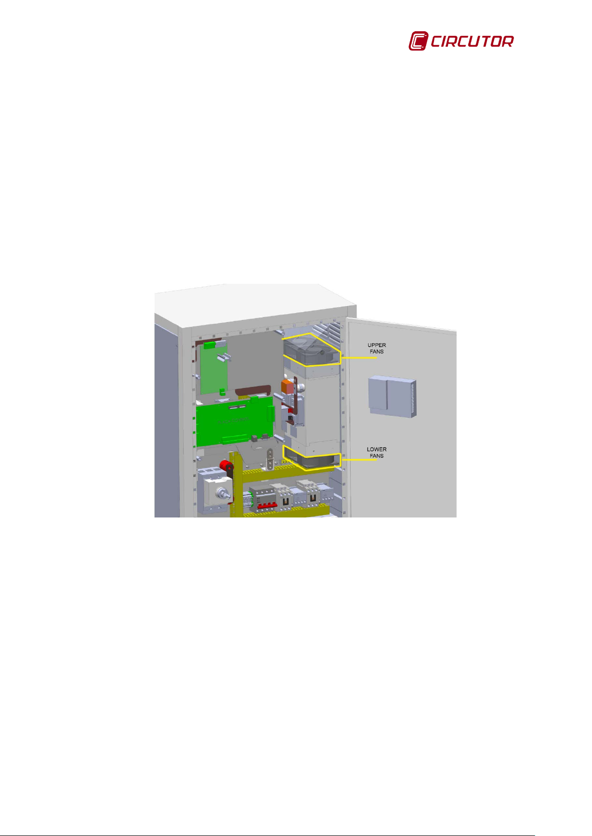
5.2. COOLING TURBINES AND FANS
overheating in the active filter components.
Table 11 gives the number of fans and/or turbines required to cool the inductors
and the semiconductors according to the active filter model.
AFQ model
AFQ-4W-100 A
Table 11 : Cooling components depending on the active filter model.
cooling fans
3 4 3 - 1
IGBT cooling fans
turbines
The following symptoms in the behaviour of the filter can indicate wear in the
fans or turbines:
Increased noise in the fan / turbine.
Increased temperature in the unit under the same environmental
conditions and load.
The AFQ-4W periodically indicates the te m p er atur e al arm.
If any sign of wear is detected, the affected fan/turbine should be replaced.
Instruction Manual 65
Page 66
AFQ-4W
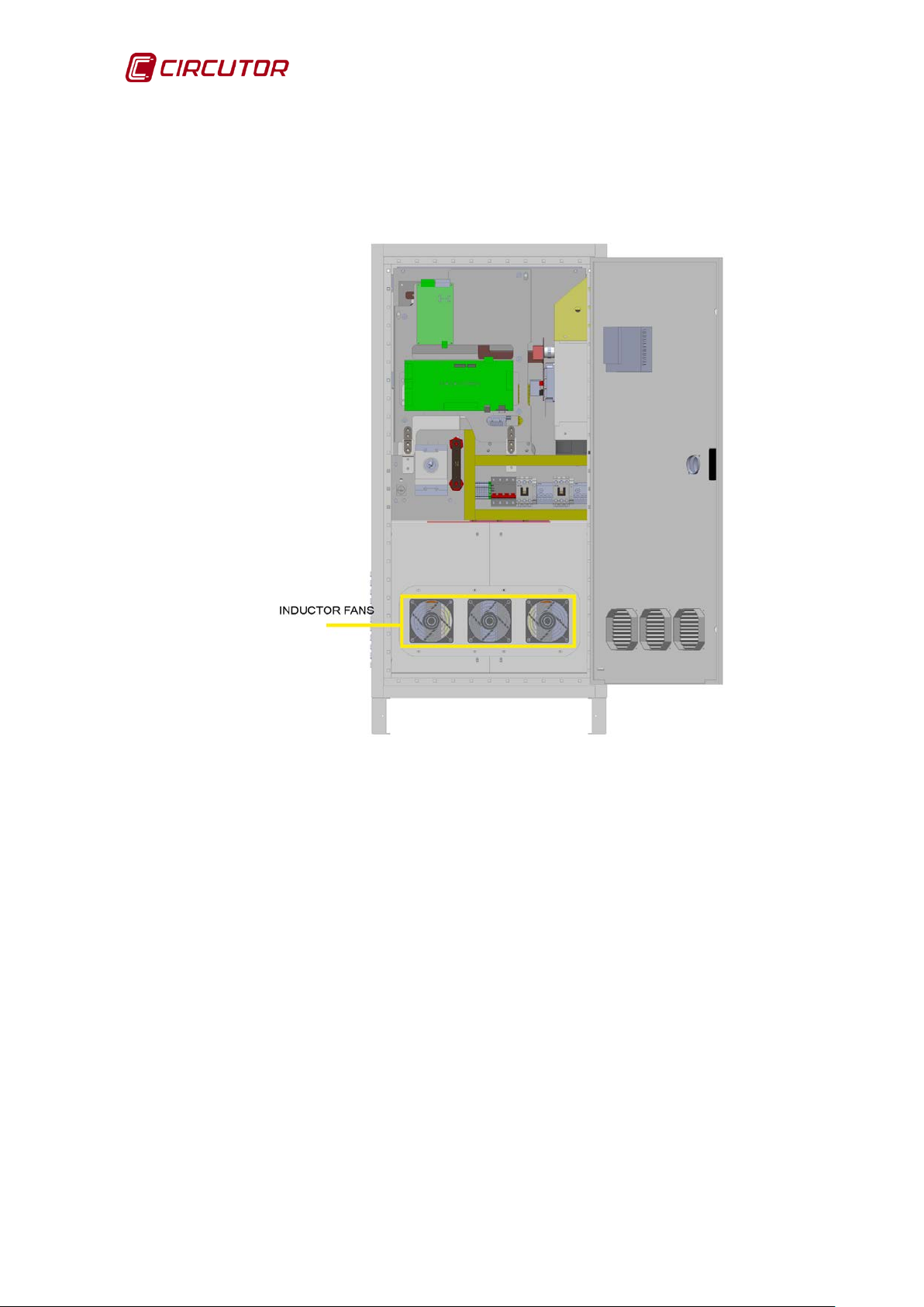
5.2.1. INDUCTOR COOLING F ANS
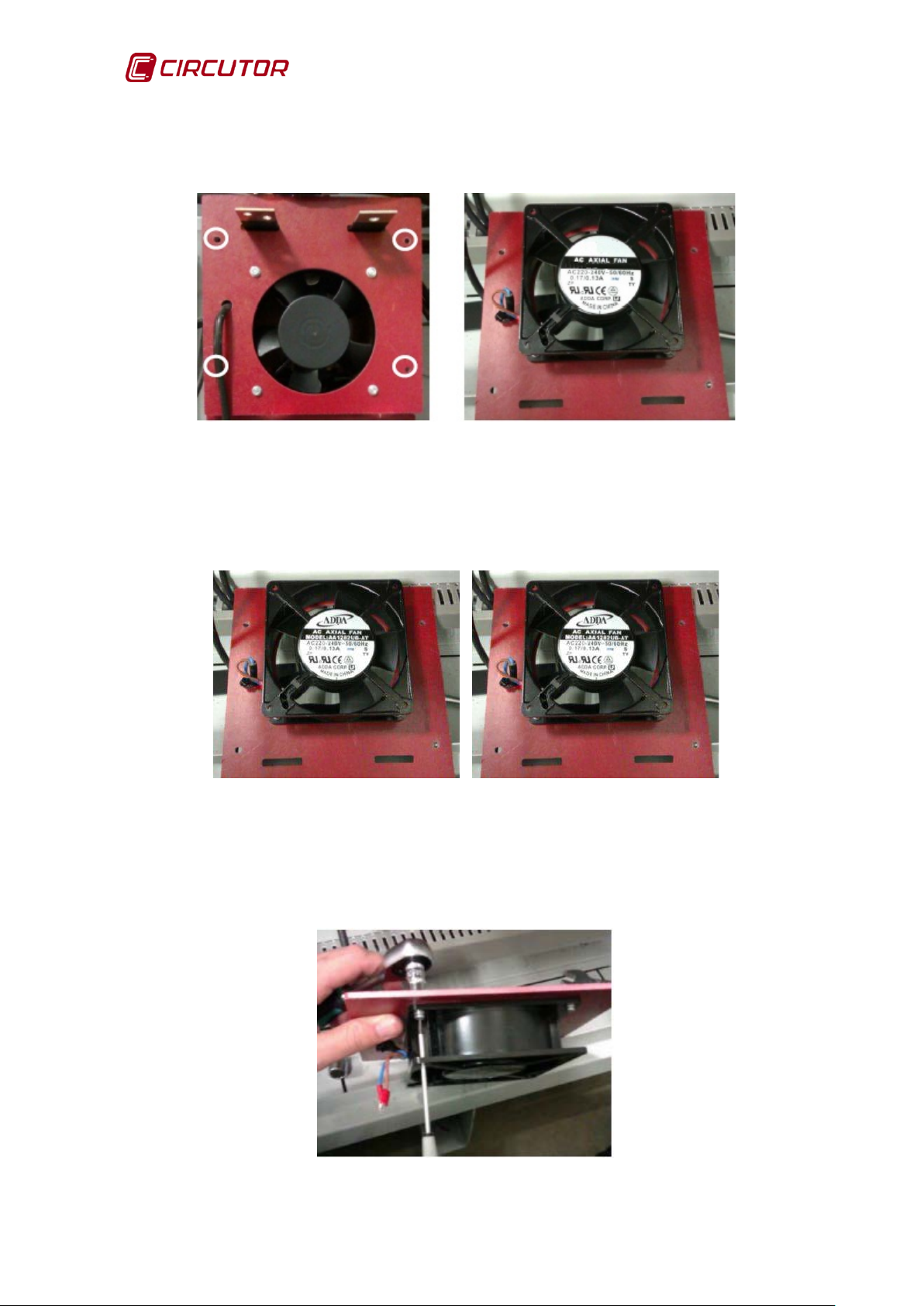
5.2.1.1. AF Q-4W-25 A / 50 A / 100 A MODELS
Follow these instructions to replace the inductor cooling fans in the AFQ-4W25A, AFQ-4W-50A and AFQ-4W-100A models:
Figure 65: Position of the inductor fans in the AFQ-4W-25, AFQ-4W-50 and AF Q-4W-100.
1.- Set the AFQ-4W to STOP mode and turn off the main switch
(OFF position).
2.- Wait 5 minutes for the energy accumulated in the capacitors to discharge.
3.- Open the AFQ-4W cabinet and disconnect the fan's power supply. (Figure
66)
The power supply terminals are located in the lower left corner of the fan. Grasp
the terminal firmly and pull to disconnect it.
66 Instruction Manual
Page 67

AFQ-4W
Figure 66: Disconnection of the fan p o wer supply.
4.- Use a 3 mm Allen key to unscrew the 4 screws fixing the fan to the front
panel. (Figure 67)
Figure 67: Unscrew the 4 screws from the fan
5.- Replace the damaged fan, connecting the power supply terminals in the
bottom left corner.
Instruction Manual 67
Page 68

AFQ-4W
6.- Use the 3 mm Allen key to fix the fan to the front panel. (Figure 68)
Figure 68: Fix the fan to the front panel.
7.-Connect the power supply terminals.
5.2.1.2. AF Q-4W-150 A / 200 A MODELS
Follow these instructions to replace the inductor cooling fans in the AFQ-4W150A, and AFQ-4W-200A models:
Figure 69: Position of the inductor fans in the AFQ-4W-150 and AFQ-4W-200 filters.
1.- Set the AFQ-4W to STOP mode and turn off the main switc h
(OFF position).
68 Instruction Manual
Page 69

AFQ-4W
2.- Wait 5 minutes for the energy accumulated in the capacitors to discharge.
3.- Remove the protection board from the inductor compartment.
(Figure 70)
Figure 70: Remove the protectio n b o ard from the inductor compartment.
4.- Take off the inductor busbars and cables. (Figure 71)
Use a 10 mm socket spanner and 5 mm Allen key to take off the cables
from the inductors' side.
Use a 13 mm socket spanner and 13 mm open-end spanner to
disconnect the cable from the mains side.
Figure 71: Take off the inductor busb ars and cables.
Instruction Manual 69
Page 70
AFQ-4W
5.- Unscrew the compartment cover fasteners with a no. 20 Torx key and remove
the cover. (Figure 72).
Figure 72: Unscrew the cover fasteners
6.- Disconnect the power supply fans by firmly grasping the terminal and pulling
to disconnect it. (Figure 73)
Figure 73: Disconnect the power suppl y from the fans.
7.-Take out the fan being changed using a socket spanner or 7 mm spanner to
hold the rear nut and a flat or Phillips screwdriver to loosen the screw. (Figure
)
74
Figure 74: Remove the fan.
70 Instruction Manual
Page 71
AFQ-4W
8.- Fix and connect the replacement fan.
9.- Fix the inductor compartment cover.
10.- Fasten the inductor cables and busbars.
11.- Fit the protection board.
5.2.2. COOLING FANS/TURBINES OF THE IGBTs
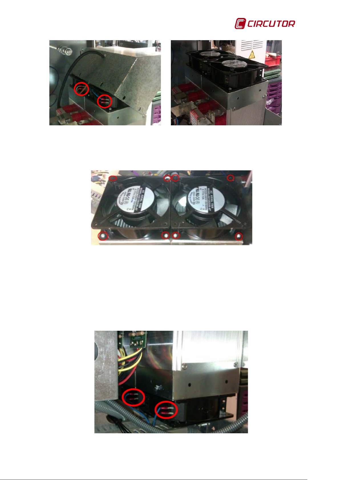
5.2.2.1. AF Q-4W-25 A / 50 A MODELS
The AFQ-4W-25 and AFQ-4W-50 active filters cool the IGBTs using fans.
The fans are fixed to the IGBT heatsink. Each unit has four fans: two on the top
and two on the bottom.
(Figure 75).
Figure 75: Position of the IGBT upper and lower fans (AFQ-4W-25 and AFQ-4W-50).
The instructions that follow must be observed in replacing the fans:
1.- Place the AFQ-4W in STOP mode and turn off the main switch
(OFF position).
2.- Wait 5 minutes for the energy accumulated in the capacitors to discharge.
3.-Remove the protection board and unfasten the front panel holding the
electronic boards. (Figure 76)
Instruction Manual 71
Page 72

AFQ-4W
Figure 76: Position of the protection board ( AFQ-4W-25 and AFQ-4W-50)
4.- Remove the right side cabinet cover.
UPPER FANS
5.- Remove the extractor hood fasteners to be able to reach the top fans. (Figure
77
)
Figure 77: Remove the fasteners from the extractor hood.
6.- Lift the extractor hood, disconnect the power supply from the fans and
remove the hood. (Figure 78)
72 Instruction Manual
Page 73
AFQ-4W
Figure 78: Disconnect the power suppl y from the fans and remove the hood.
7.-Remove the four fan screws to extract them.(Figure 79)
Figure 79: Remove the fan screws.
8.- Replace the damaged fans. Fit the fan, leaving the power supply pins on the
side of the IGBTs
9.- Pass the power supply cable through the drill hole on the hood.
10.- Connect the power supply of the two fans.
11.- Screw back on the extractor hood fasteners.
LOWER FANS
12.- Remove the power supply cable from the bottom heatsink fans. (Figure 80)
Figure 80: Remove the power supply cable
Instruction Manual 73
Page 74

AFQ-4W
1 2 3 5 4
13.- Reach into the fans from the side and remove the right fan fasteners. It is
best to follow the order of the steps shown in Figure 81.
Figure 81: Remove the fan fasteners on the right.
14.- Remove the left fan by unscrewing the four fasteners.
15.- Replace the left fan with a new one.
16.- Replace the fan on the right.
17.- Connect the fan power supply cables.
18.- Lift up and attach the front panel metal plate.
19.- Fit the protection boar d.
20.- Fit the side cover.
21.- Start up the unit and check that the fans operate correctly.
74 Instruction Manual
Page 75
AFQ-4W
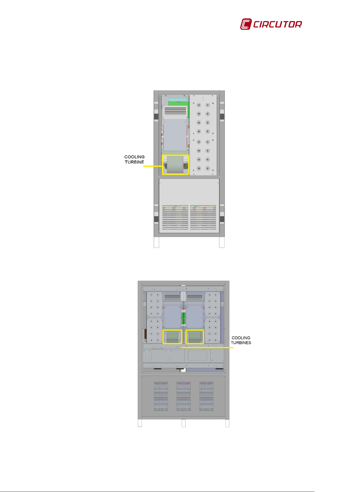
5.2.2.2. AF Q-4W-100 A / 150 A / 200 A MODELS
The AFQ-4W-100A, AFQ-4W-150A and AFQ-4W-200A active f ilters
cool the IGBTs using turbines.
Figure 82: Position of the cooling turbine in the AFQ-4W-100.
Figure 83: Position of the cooling turbines in the AFQ-4W-150 and AFQ-4W-200 filters.
Instruction Manual 75
Page 76

AFQ-4W
5 4 6 5 7
The instructions that follow must be observed:
1.- Place the AFQ-4W in STOP mode and turn off the main switch
(OFF position).
2.- Wait 5 minutes for the energy accumulated in the capacitors to discharge.
3.- Remove the front panel pr otect ion board.
4.- Drop the front panel metal plate. (Figure 84)
5.- Remove the DC bus busbar. (Figure 84)
6.- Disconnect the earth wire from the front panel metal plate. (Figure 84)
7.- Remove the top crossbar. (Figure 84)
Figure 84: Steps 4, 5, 6 and 7
8- Remove the back cabinet cover. The side cabinet covers can be removed if
more space or light is needed during these procedures.
9.- Disconnect the inverter bridge R-S-T phases. (Figure 85)
Figure 85: Disconnect the inverter bridge R-S-T phases.
76 Instruction Manual
Page 77

AFQ-4W
10.- Disconnect the IGBT connectors from the gate board. The top board must
first be removed to be able to disconnect the IGBTs from the bottom board.
11.- Disconnect the NTC connectors from the controller board
12.- Take the NTC probe cabling out of the channel.
13.-. Disconnect the turbine power supply.
The location of the power supply depends on the turbine model.
If the turbine is black, the power supply is on the front part (Figure 86).
Figure 86: Disconnect the turbine power supply (black turbine).
If the turbine has a steel finish, the power supply is on the rear part
(Figure 87).
Figure 87: Disconnect the turbine power supply (steel turbine).
Instruction Manual 77
Page 78

AFQ-4W
14.- Unscrew the extrac tor hood fas te ner s on the back met al pla te (Figure 88).
Figure 88: Unscrew the fasteners from the extractor hood.
15.- Remove the screws fastening the heatsink to the hood. (Figure 89)
Figure 89: Remove the screws fastening the heatsink to the hood.
16.- Unscrew the botto m fasten er s fro m the p ac k for med by the heat s i nk body,
the turbine and the IGBT bridge while the whole pack is held.
It is best to have two people do this task. (Figure 90)
78 Instruction Manual
Page 79

AFQ-4W
Figure 90: Unscrew the bottom fasten ers.
17.- Move the pack towards the bottom until the heatsink comes out of the
extractor hood. (Figure 91)
18.- Tilt the pack towards the outside of the cabinet and remove it. (Figure 91)
Figure 91: Remove the pack fr o m the cabinet.
19.- Place the pack on a flat, stable surface to unscrew the turbine fasteners.
(Figure 92)
Instruction Manual 79
Page 80

AFQ-4W
Figure 92: Unscrew the turbine fasteners
20.- Replace the turbine with the spare.
21.- Reinsert the pack into the cabinet.
22.- Fix the extractor hood.
23.- Connect the turbine power supply.
24.- Connect the R-S-T phases to the inverter bridge.
25.- Put the NTC probe cable back in the channel.
26.- Connect the NTC probe.
27.- Connect the IGBTs to the driver board and reinstall the driver board if
necessary.
Respect the R-S-T order of the connectors.
28.- Connect the DC bus busbar.
29.- Insert the top crossbar of the AFQ-4W cabinet.
30.- Connect the earth wire to the front panel metal plate of the AFQ-4W.
31.- Fit the protection boar d.
32.- Check that the turbine operates correctly.
80 Instruction Manual
Page 81
AFQ-4W
The version of the controller software and the display software must
ctive
5.3. DC BUS CAPACITORS
The DC bus capacitors have a useful life of 200,000 hours (22 years). The
capacitor life depends on the operation of the active filter and the environmental
conditions and, especially, on the ambient temperature.
The active filter capacitors are maintenance-free, except when the unit is started
up after long storage (Refer to 3.3.- STORAGE FOR LONG PERIODS.).
6.- SOFTWARE UPDATE
The AFQ-4W software can be updated with a memory that should be supplied
by the CIRCUTOR technical service.
The complete software update of the unit is divided into two parts:
1.- Controller software update.
2.- Display software update.
The material required for the full update is:
CIRCUTOR memory stick
USB m emory stick with the Vx.yz_CIRCUTOR software ( x.yz: software
version no.)
be the same. Two different software versions can leave the a
filter inoperative.
To check the current version of the software, access the filter data screen
(Section 4.3.4.- FILTER DATA).
6.1. CONTROLLER SOFTWARE UPDATE
Update the unit controller software as follows:
1.- Place the AFQ-4W in STOP mode and turn off the main switch
(OFF position).
2.- Wait 5 minutes for the energy accumulated in the capacitors to discharge.
3.- Remove the protection board to access the controller board.
4.- Locate the controller board.
If the board has micro-switches, move the two micro-switches closest to the
Instruction Manual 81
Page 82

AFQ-4W
battery. If the board has jumpers, move the two jumpers closest to the battery. If
the initial status was “0000”, now it should be “0011”. (Figure 93)
Figure 93: Change the position o f th e jumpers (A) or micro switches (B)
5.- Connect the memory stick supplied by CIRCUTOR to port J12 next to the
micro-switches or jumpers.
It should be connected with the fat side facing the battery. (Figure 94)
Figure 94: Connect the memory stick to port J12
6.- Close the filter door and power it up.
7.- Wait 2 minu tes and turn off the AFQ-4W once more. The updating process
should have finished.
8.- Turn off the unit and wait 5 minutes for the energy accumulated in the
capacitors to discharg e.
9.- Open the filter door.
10.- Disconnect the memory stick.
11.-Change the position of the micro-switches or the jumpers to the initial
configuration “0000”.
12.- Fit the protection boar d.
82 Instruction Manual
Page 83

AFQ-4W
If the display software is not updated, update this software before
When the controller software update is complete, it may be necessary
following an update, check all of the configuration
The controller software update is complete.
starting up the unit. (Section 6.2)
to reconfigure the unit parameters. Before starting up the AFQ-4W
parameters.(Section 4.3.)
6.2. DISPLAY SOFTWARE UPDATE.
To update the panel software:
a USB memory stick
the update file Vx.yx_CIRCUTOR. ( x.yz: software version number)
Follow the steps below to update the display software:
1.- Copy the file XP_Project in the root directory of the memory stick.
Omit this step if you have a CIRCUTOR memory stick
If the XP_Project file is compressed in a *.rar format, unzip the file and copy it to
the memory stick in the directory:
(USB memory root):\XP_Project\Vx.yz_CIRCUTOR
2.- Place the AFQ-4W in STOP mode and turn off the main switch
(OFF position).
3.- Wait 5 minutes for the energy accumulated in the capacitors to discharge.
4.- With the unit turned off, open the front door and plug the memory stick into
the USB port located behind the screen. (Figure 95)
Instruction Manual 83
Page 84

AFQ-4W
USB port
Figure 95: USB port
4.- Close the front door of the unit.
5.- Turn on the unit and wait for the screen to start up.
6.- Check that the filter is “STOP”.
7.- Access the FILTER DATA menu (Section 4.3.4) and change the
configuration code 14 for 25. (Figure 96)
Figure 96: Change the Configuration code.
8.- Access the screen configuration (Section 4.3.5) and press EXIT to access
the internal menu. (Figure 97)
84 Instruction Manual
Page 85

AFQ-4W
Figure 97: Press EXIT to access the screen setup menu.
9.- Press Storage Function in the internal screen setup menu. ( Figure 98)
If the error message “Cannot find any removable Storage” appears,
disconnect the memory stick from the USB port and connect it again.
Figure 98: Press Storage Function
10.- Press the “Project Download” option (Figure 99).
Instruction Manual 85
Page 86

AFQ-4W
When the display software update is complete, it may be necessary to
following an update, check all of the configuration
Figure 99: Press Project Download.
11.- Select the file Vx.yz_CIRCUTOR and press OK.
12.- Wait until the updating process ends. When the process ends, the active
filter main screen will appear.
13.- Turn off the active filter and wait for the energy accumulated in the
capacitors to discharg e. Di sc on nect the m em ory stick.
14.- Power up the active filter once more.
If the End Configuration message appears, open the FILTER DATA screen and
program the configuration code 14. Return to the main screen and check that the
message no longer appears.
If the Error in the modules in parallel message appears, open the
PARAMETERS screen. Press MODULES IN PARALLEL and enter the number
of active filters installed in parallel. Check section 4.3.3.- CONFIGURATION OF
PARAMETERS
If the controller software is not updated, update this software before
starting up the unit. (Section 6.1)
reconfigure the unit parameters. Before starting up the AFQ-4W
parameters.(Section 4.3.)
86 Instruction Manual
Page 87

AFQ-4W
Models
Harmonic phase
Harmonic neutral
Harmonic peak
Max.
ELECTRICAL FEATURES
Rated voltage
400 V ± 15%
Mains frequency
50 Hz / 60 Hz - 4%
Connection
3 phases with neutral (4 wires)
FILTER SPECIFICATIONS
Harmonic compensation
from the 2nd to the 50th harmonic
Specific harmonics selection
from the 2nd to the 50th harmonic
Phase balancing
Yes
Reactive current compensation
Yes
Controller
Digital, DSP
Response time
< 1ms
Yes, when the nominal current of the filter is
User interface
LCD Screen, 5.7” 320x240 pixel
ENVIRONMENTAL FEATURES
Operating temperature
0ºC to +40ºC
Relative humidity
0% to 90% (without condensation)
Maximum altitude
< 2000 m
Storage temperature
0ºC to +50ºC
MECHANICAL FEATURES
Models
Dimensions (WxHxD) (mm)
500x830x450
655x1350x450
655x1470x450
Weight (kg)
135
212
272
Models
Dimensions (WxHxD1xD2)
Weight (kg)
505
511
7.- TECHNICAL FEATURES
AFQ-4W-25 AFQ-4W-50 AFQ-4W-100 AFQ-4W-150 AFQ-4W-200
current
current
current
consumption.
25A
75A
50A
50A
RMS
150A
RMS
100A
PEAK
100A
RMS
300A
RMS
200A
PEAK
150A
RMS
450A
RMS
300A
PEAK
200A
RMS
600A
RMS
400A
PEAK
PEAK
1000W 1700W 3500W 5700W 6100W
RMS
RMS
Saturation protection
(mm)
exceeded
AFQ-4W-25 AFQ-4W-50 AFQ-4W-100
AFQ-4W-150 AFQ-4W-200
1190x1900x620x720 1190x1900x620x720
Instruction Manual 87
Page 88

AFQ-4W
STANDARDS
Harmonic regulation
EN61000-3-4, IEEE519-1992
Electrical specifications
EN60146
Electrical safety
EN50178
EN55011, EN50081-2, EN61000-4-2, EN6100 0-4-3,
Figure 100: Dimensions of AFQ-4W (25A, 50A, 100A)
Figure 101: Dimensions of AFQ-4W (150A, 200A)
Electromagnetic compatibility
88 Instruction Manual
EN61000-4-4, EN61000-4-5, EN61000-4-6,
EN61000-6-2
Page 89

AFQ-4W
• No returns will be accepted and no unit will be repaired or replaced if it is
not accompanied by a report indicating the defect detected or the reason
r the
storage, installation and maintenance instructions listed in this manual
have not been followed. "Improper usage" is defined as any operating or
storage condition contrary to the national electrical code or that
technical and environmental
8.- MAINTENANCE AND TECHNICAL SERVICE
In the case of any query in relation to unit operation or malfunction, please
contact the
CIRCUTOR, SA
Technical Support Service.
Technical Assistance Service
Vial Sant Jordi, s/n 08232 - Viladecavalls (Barcelona)
Tel.: 902 449 459 (Spain) / +34 937 452 900 (outside of Spain)
email: sat@circutor.es
9.- GUARANTEE
CIRCUTOR guarantees its products against any manufacturing defect for two
years after the delivery of the units.
CIRCUTOR will repair or replace any defective factory product returned during
the guarantee period.
for th e return.
The guarantee will be void if the units has been improperly used o
•
surpasses the limits indicated in the
features of this manual.
CIRCUTOR
•
other parts of the installation, nor will it cover any possible sanctions
derived from a possible failure, improper installation or "improper usage"
of the unit. Consequently, this guarantee does not apply to failures
occurring in the following cases:
- Overvoltages and/or electrical disturbances in the supply;
- Water, if the product does not have the appropriate IP classification;
- Poor ventilation and/or excessive temperatures;
- Improper installation and/or lack of maintenance;
- Buyer repairs or modifications without the manufacturer's authorisation.
accepts no liability due to the possible damage to the unit or
Instruction Manual 89
Page 90

AFQ-4W
10.- CE CERTIFICATE
90 Instruction Manual
Page 91

AFQ-4W
Wait until the initialisat io n is c omp le te.
232
transformer is not
The load current is below the minimum limit programmed in the
AFQ-4W
Corrective
The minimum c urrent of t he AFQ-4W can be changed in section
Corrective
Check the input voltage of the three phases of the AFQ-4W and
APPENDIX A : DISPLAY MESSAGES
The tables below show all of the messages that might appear on the main
screen, along with the description and the corresponding corrective action.
Disconnect the main switch before starting any maintenance task on
the AFQ-4W filters. After the main switch has been disconnected,
wait at least 5 minutes to ensure that all the DC side capacitors and
the parallel passive filter are completely discharged.
ACTIVE FILTER STOPPED
Table 12 shows the messages that might appear on the main screen before the
AFQ-4W starts up.
NOT INITIAL CONDITIONS (Initial conditions not met)
Description AFQ-4W is st a rt ing
Corrective
Action
Description
Corrective
Action
If the message is still displayed, check the RScommunications cable between the panel and the controller board.
The transformation ratio of the load measuring
configured.
Check section 4.3.3.- CONFIGURATION OF PARAMETERS
to configure the transformer ratio.
Starting ...
Set Up transformer ratio
MIN. Load current
Description
Action
Description
Action
Mains voltage too low.
the circuit breaker 1Q22.
.
4.3.3.- CONFIGURATION OF PARAMETERS
Mains voltage fault.
Instruction Manual 91
Page 92

AFQ-4W
Corrective
Check the input voltage of the three phases of the AFQ-4W and
Corrective
Action
Check the input voltage and the connections if the message
Check the unit
Corrective
The NTC temperature probe is disconnected or the temperature
Make sure the NTC probe is connected to the controller board.
If the temperature inside the cabinet is under 0ºC, do not start the
unit.
MIN. DC bus voltage
Description
Action
Description
Description
Corrective
Action
Description
The DC bus voltage is too low.
the circuit breaker 1Q22.
Synchronising
Synchronising with the mains frequency.
remains on the screen.
Polarity Error
Error measuring the load current.
Check the measuring transformers connection.
configuration, 4.3.2.- OPERATION MODE CONFIGURATION.
DC Bus imbalance
The capacitor voltage is decompensated.
Action
Description
Corrective
Action
Reduce the number of harmonics to be neutralised.
NTC connector failure
inside the unit is below 0ºC.
Table 12: Not Initial Conditions messages.
92 Instruction Manual
Page 93

AFQ-4W
that the fans or turbines at the top of the cabinet are
Corrective
Ensure that the fans at the bottom of the cabinet are operating
Corrective
Action
Corrective
Corrective
ACTIVE FILTER IN ALARM STATUS
Table 13 shows the messages that might appear on the main screen when the
AFQ-4W is in an alarm status.
ALARM
NTC1 temperature
Description
Corrective
Action
Description
Corrective
Action
Description
Action
Description
NTC probe overtemperature.
Make sure
operating properly.
NTC2 temperature
NTC probe overheating
Make sure that the fans or turbines at the top of the cabinet are
operating properly.
Inductor Temperature
Inductor overtemperature
properly.
MAX. DC bus voltage.
The voltage on the DC bus capacitors is too high.
Check the unit connections and the input voltages.
MAX. Bus positive voltage
Description
Action
Description
Action
Description The AFQ-4W current is too high.
The voltage on the DC bus capacitors is too high.
Check the unit connections and the input voltages.
MAX. Bus negative voltage
The voltage on the DC bus capacitors is too high.
Check the unit connections and the input voltages.
MAX. Current
Instruction Manual 93
Page 94
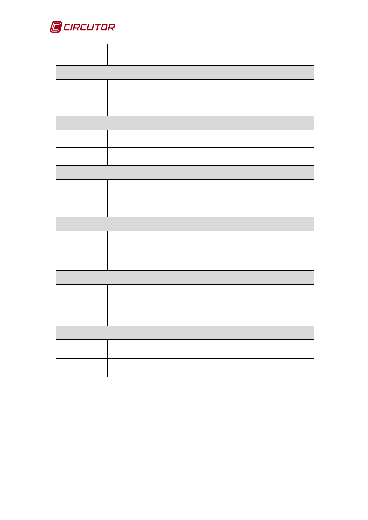
AFQ-4W
Corrective
Corrective
Corrective
Corrective
Ensure that the filter is operating in frequency mode. Refer to
The cabinet contactors do not work correctly or a circuit breaker
Check the cabling of the contactor auxiliary contacts and the circuit
Corrective
Corrective
Action
Description
Action
Description
Action
Description
Action
Check the unit connections or reduce the harmonics to be filtered.
MAX. Mains voltage
The mains voltage is too high.
Check the AFQ-4W input voltage levels.
Desaturation
Problem related to the inverter drivers.
Check the connections of the controller boards.
Initial Conditions Error
An alarm caused by repeated no initial conditions.
Check the initial conditions and the configuration.
Resonance Alarm
Description
Action
Description
Corrective
Action
Description
Action
An alarm caused by the resonance of a harmonic current with load.
section 4.3.3.- CONFIGURATION OF PARAMETERS
Contactor faults
has tripped.
breakers.
DC Bus Load Error
The DC bus voltage is not sufficient for the proper unit operation.
Check the connections of the controller boards.
Table 13: Alarm messages.
The RESET ALARM button of the main screen rearms the unit if the cause of
the alarm has disappeared or bee n solved.
94 Instruction Manual
Page 95

AFQ-4W
The AFQ-4W is op erating pr operly but working in satur ation. The num ber
The unit is factory configured.
The unit is factory configured.
The unit is factory configured.
technical
ACTIVE FILTER OPERATING
Table 14 shows the messages that might appear on the main screen when the
AFQ-4W is operating.
START
MAX. Load current.
Description
Corrective
Action
The load harmonics are higher than the filter nominal current.
of harmonics to be filtered or the unit power should be reduced. Check
section
4.3.- CONFIGURATION.
Table 14: Operation messages.
ACTIVE FILTER IN CONFIGURATION
Table 15 shows the messages that might appear on the main screen when the
AFQ-4W is in configuration status.
CONFIGURATION
Complete configuration
Description
Corrective
Action
The configuration code is not correct
If any of the configuration messages should appear, c ontact the technical
service.
Filter range error
Description
Corrective
Action
Description The AFQ-4W in parallel configuration number is wrong.
Corrective
Action
Description
Instruction Manual 95
The configured filter range is not correct.
If any of the configuration messages should appear, contact the technical
service.
Error in the modules in parallel
If any of the configuration m essages should appear, c ontact the
service.
Error in the control algorithm
The number identifying the control algorithm is wrong.
Page 96

AFQ-4W
The unit is factory configured.
The screen software version is not the same as the controller board
The unit is factory configured.
The value of the po wer lim it par ameter is wrong. It will configure a value of
The unit is factory configured.
contact the technical
Corrective
Action
Description
Corrective
Action
Description
Corrective
Action
If any of the configuration m essages should appear, c ontact the technical
service.
Error in the software version
software version.
If any of the configuration m essages should appear, c ontact the technical
service.
Error in AFQ-4W power limit
between 20% and 100%
If any of the configuration m essages should appear,
service.
Table 15: Configuration Messages.
96 Instruction Manual
Page 97

AFQ-4W
Name
Type
Function
Address (Hexadecimal)
Buttons
Bit
R/W
0000
Bit
Response
Description
0:
1:
0: Rearm alarm
1:
Name
Type
Function
Address (Hexadecimal)
Flags
Bit
R/W
0001
Bit
Response
Description
8
Harmonic filtering flag
9
Phase current balancing flag
A
Reactive current compensation flag
0: Priority in harmonic filtering
reactive compensation
C
Polarity alarm tripping flag
D
Low temperature alarm tripping flag
E
Resonance alarm tripping flag
Name
Type
Function
Address (Hexadecimal)
Harmonic filtering flags
Bit
R/W
0002
Bit
Description
0
Harmonic 3 filtering flag
1
Harmonic 5 filtering flag
2
Harmonic 7 filtering flag
3
Harmonic 9 filtering flag
4
Harmonic 11 filtering flag
5
Harmonic 13 filtering flag
6
Harmonic 15 filtering flag
7
Harmonic 17 filtering flag
8
Harmonic 19 filtering flag
9
Harmonic 21 filtering flag
A
Harmonic 23 filtering flag
B
Harmonic 25 filtering flag
Name
Type
Function
Address (Hexadecimal)
AFQ status
Word R 000F
Response
0: No connection
9:
APPENDIX B: MODBUS MAP
0
2
Stop
Start
OK
Start/Stop button
Alarm reset
1: Priority in balancing and
B
Order of priorities flag
1,2: Not initial conditions
3: Stop
4, 5, 6: Operation
7: Alarm
8: Calibration
Configuration
Instruction Manual 97
Page 98

AFQ-4W
Name
Type
Function
Address (Hexadecimal)
AFQ incidents
Word R 0010
Response
0: OK (no incidents)
40:
Name
Type
Function
Address (Hexadecimal)
Transformer rati o
Word
R/W
0014
Response
Description
1: MAXIMUM DC bus voltage
2: MAXIMUM Current L1
3: MAXIMUM Current L2
4: MAXIMUM Current L3
5: MAXIMUM Mains voltage L1
6: MAXIMUM Mains voltage L2
7: MAXIMUM Mains voltage L3
8: MAXIMUM DC bus positive voltage
9: MAXIMUM DC bus negative voltage
10: Desaturation
11: Desaturation L1
12: Desaturation L2
13: Desaturation L3
14: Desaturation LN
15: MAXIMUM NTC1 temperature
16: MAXIMUM NTC2 temperature
17: Error in initial conditions
18: Resonance alarm
19: MAXIMUM Inductor temperature
20: DC bus load error
21: MINIMUM DC bus voltage
22: MINIMUM Load current
23: Mains voltage fault
24: Polarity error
25: Starting up
26: DC bus imbalance
27: Contactor faults
28: NTC connector fault
30: Complete configuration
31: Filter range error
32: Synchronising
33: Transformer ratio configuration
34: Error in the control algorithm
35: Error in the parallel modules
36: Error in the software versions
37: Error in the AFQ-4W power limit
Maximum load current
5, 10, 15, 20, 25, 30, 40, 50, 60, 75, 100, 125, 150, 200, 250,
300, 400, 500, 600, 700, 750, 800, 1000, 1200, 1500, 1600,
2000, 2500, 3000, 4000, 5000, … /5 A
98 Instruction Manual
Load measuring transformer
ratio xxx/5
Page 99

AFQ-4W
Name
Type
Function
Address (Hexadecimal)
Minimum load current
Word
R/W
0015
Response
Description
Minimum load current to start the
AFQ-4W
Name
Type
Function
Address (Hexadecimal)
AFQ range
Word
R/W
0016
Response
Description
25 / 50 / 100 / 150 / 200
Unit range. WARNING: DO NOT MODIFY
Name
Type
Function
Address (Hexadecimal)
Configuration code
Word
R/W
0017
Response
14: Complete configuration
25: Enter AFQ-4W configuration
Name
Type
Function
Address (Hexadecimal)
AFQ software version
Word
R
0018
Response
Description
Response format X.XX
AFQ s of t ware vers io n
Name
Type
Function
Address (Hexadecimal)
Control algorithm
Word
R/W
0019
Response
Description
1:
2:
Name
Type
Function
Address (Hexadecimal)
Parallel AFQ number
Word
R/W
001A
Bit
Response
Description
Response in Amps without dec imals.
Frequency mode
Temporary mode
0
1
2
3
4
5
6
7
8
9
A
B
No. of AFQ-4W 25A
Numbering from 0 to 7
No. of AFQ-4W 50A
Numbering from 0 to 7
No. of AFQ-4W 100A
Numbering from 0 to 7
No. of AFQ-4W 150A
Numbering from 0 to 7
Control algorithm selection
Number of AFQ-4W installed in parallel.
The value is coded in 16 bits.
The consulted unit counts as 1u.,
Note
so the minimum value will be 001 for the
consulted range.
C
D
E
F
Instruction Manual 99
No. of AFQ-4W 200A
Numbering from 0 to 7
F:0 No. AFQYY <= 7 units
F: 1 No. AFQYY == 8
where YY: Range of AFQ 25,
50, 100, 150, 200
Flag indication of 8 AFQ-4W of the
same range in parallel
Page 100
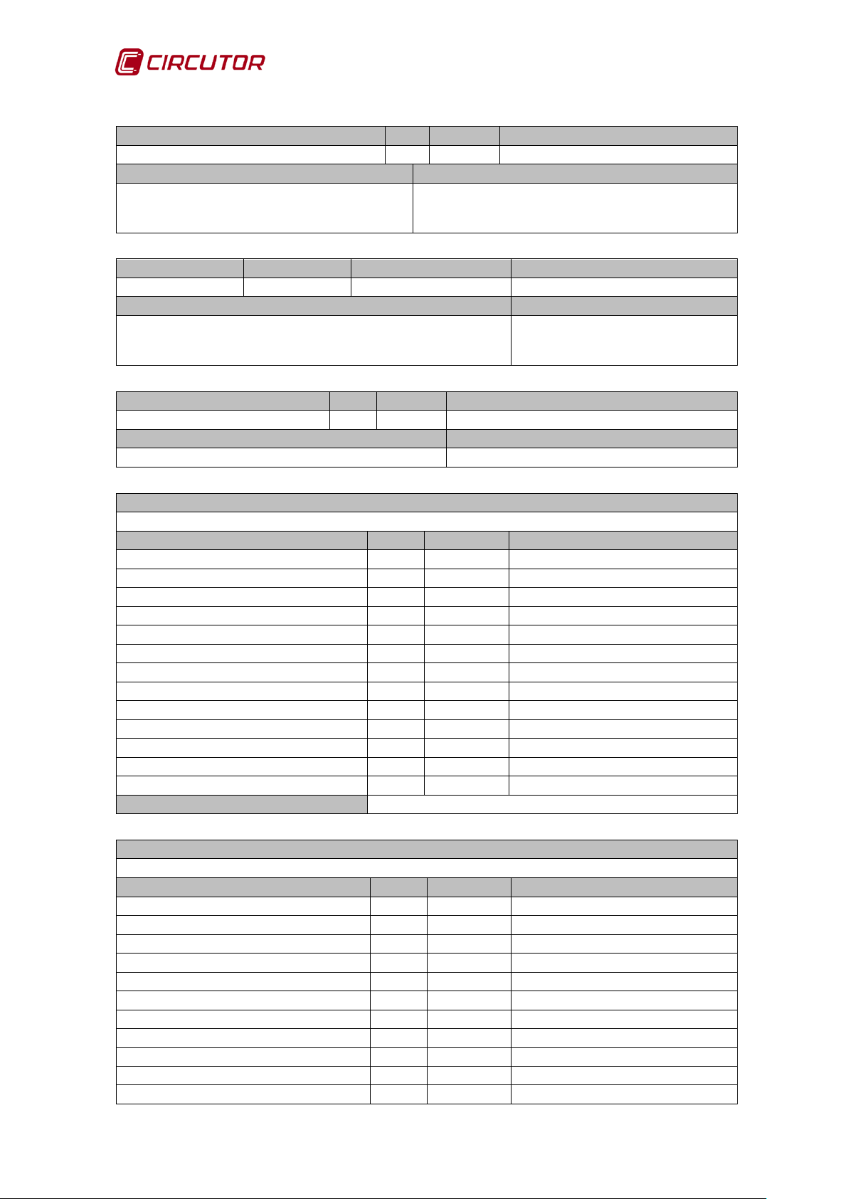
AFQ-4W
Name
Type
Function
Address (Hexadecimal)
Serial number high (001B) + low (001C)
Word
R
001B - 001C
Response
Description
Reading of two logs (001B - 001C) which form
This number is formed by 4 bytes. [HL HL]
Name
Type
Function
Address (Hexadecimal)
Power limit
Word
R/W
001D
Response
Description
20 <= Limit <= 100
without decimals.
Name
Type
Function
Address (Hexadecimal)
Panel software version
Word
R
001E
Response
Description
Response format X.XX
Panel software version
Name
Mains current harmonics L1
Name
Type
Function
Address (Hexadecimal)
1st Mains current harmonic L1
Word
R
003C
3rd Mains current harmonic L1
Word
R
003D
5th Mains current harmonic L1
Word
R
003E
7th Mains current harmonic L1
Word
R
003F
9th Mains current harmonic L1
Word
R
0040
11th Mains current harmonic L1
Word
R
0041
13th Mains current harmonic L1
Word
R
0042
15th Mains current harmonic L1
Word
R
0043
17th Mains current harmonic L1
Word
R
0044
19th Mains current harmonic L1
Word
R
0045
21st Mains current harmonic L1
Word
R
0046
23rd Mains current harmonic L1
Word
R
0047
25th Mains current harmonic L1
Word
R
0048
Response
1st harmonic response in % without decimals.
Name
Mains current harmonics L2
Name
Type
Function
Address (Hexadecimal)
1st Mains current harmonic L2
Word
R
0050
3rd Mains current harmonic L2
Word
R
0051
5th Mains current harmonic L2
Word
R
0052
7th Mains current harmonic L2
Word
R
0053
9th Mains current harmonic L2
Word
R
0054
11th Mains current harmonic L2
Word
R
0055
13th Mains current harmonic L2
Word
R
0056
15th Mains current harmonic L2
Word
R
0057
17th Mains current harmonic L2
Word
R
0058
19th Mains current harmonic L2
Word
R
0059
21st Mains current harmonic L2
Word
R
005A
HH LL HH LL in hexadecimal
Value in % with respect to the nominal power of the unit
the serial number.
Maximum power limit of the AFQ
in %
100 Instruction Manual
 Loading...