

Page 1
SubAudible
Tone Decoder
Model: Sub-03
CircuitWerkes
Technical Manual
CircuitWerkes
3716 SW 3
(352) 335-6555 · Fax (352) 331-6999
c 1997 CircuitWerkes All Rights Reserved. All information contained within is proprietary.
No part of this manual may be reproduced or copied without the express written consent of CircuitWerkes.
rd
Place · Gainesville, FL 32607
Page 2

Notes:
Page 3

The CircuitWerkes Subaudible Tone Decoder
Description
The CircuitW erkes Subaudible Tone Decoder provides a reliable and accurate solution for
decoding subaudible tones from satellite, automation, or other sources of audio. The unit has dry
relay contacts and an LED indicator for each of the standard three subaudible signals, 25HZ, 35Hz
and the Combination of 25HZ and 35Hz.
The audio input can accept balanced or unbalanced audio at input levels of -20dBm to 0dBm.
The output is balanced transformerless and is easily capable of driving a 600 ohm load. Subaudible
tones are typically attenuated by 30dB at the audio output and it is short-circuit protected.
Installation
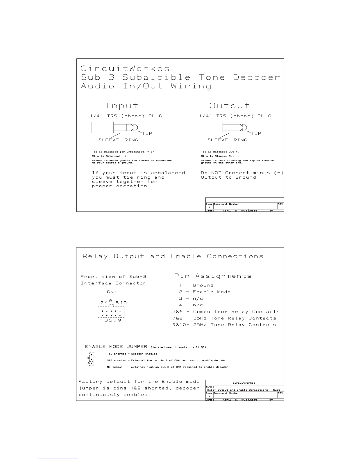
Connections to the Subaudible Tone decoder are fairly straight forward. Your audio passes through
the decoder via the Audio In and Audio Out jacks. Relay outputs and the enable line are brought out
to the ten conductor pin connector CN4. See page 3 for connection details. The mating connector
for the 10 conductor pin connector is supplied with your Subaudible Decoder . The pins are crimped
onto 20 to 26 AWG wire with a generic DB style connector crimper (available just about anywhere
that computer connectors are sold...even Radio Shack).
Power is provided by the included "wall-wart." Optionally you can power your decoder with any
supply of 12-18 Volts AC or DC.
The relay outputs are dry N.O. contacts capable of switching loads up to 10 watts. We recommend
slave relays if you intend to switch heavy loads or high voltages.
Important Note regarding program content...
If your subaudible tone decoder is connected to a source that delivers more than one program and
one or more of the programs delivered does not contain subaudible tone signalling you may encounter
(easily resolved) problems. Any program that does NOT contain subaudible signalling tones probably
DOES have subaudible content. Normal voice and background noise can easily set off your decoder's
outputs if the audio is not (high pass) filtered. Programs that do contain subaudible signalling tones
will always be prefiltered at their origination point before subaudible tones are injected, thus keeping
the natural low frequency content of normal voice and noise from false tripping decoders down the
line.
A good example would be an SCPC satellite receiver that you use for a couple of different network
feeds. One of the networks uses subaudible tone signalling for starting local breaks, the other uses
DTMF T ones. The network that uses DTMF tones probably does not filter out the subaudible
portion of their program audio. If you have a limited number of inputs on your console or
automation system, you may not wish to take up two inputs with audio from one source. Fortunately
the CircuitW erkes Subaudible Tone Decoder features a jumperable ENABLE line. The ENABLE
MODE jumper is located near the five transistors on the board (Q1-Q5). When the jumper is in the
1-2 position, the decoder is enabled and will respond to 25Hz and/or 35Hz information. When the
jumper is in the 2-3 position, the decoder requires a low (with a 20mA sink capacity) on pin 2 of CN4
to enable it. If no jumper is installed, the decoder requires a TTL or CMOS high on pin 2 of CN4 to
operate.
Page 4
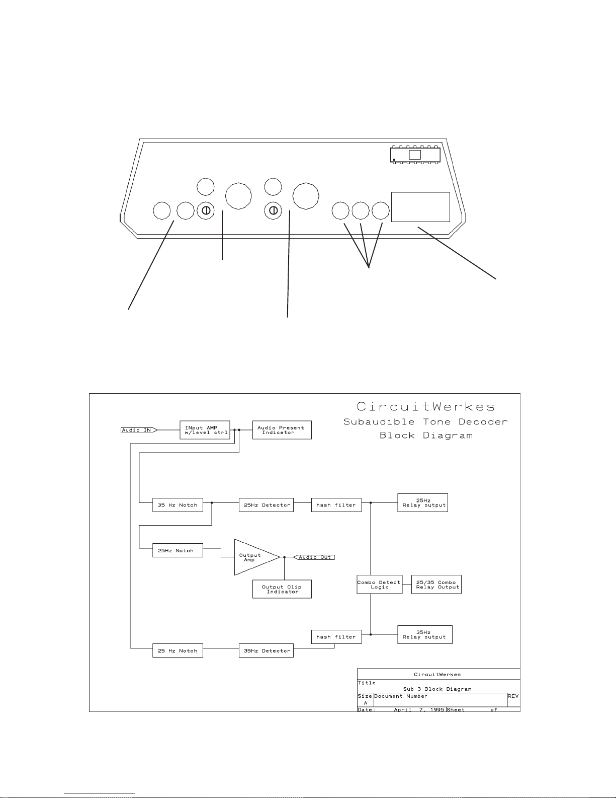
The subaudible T one Decoder's Front Panel is shown below.
CircuitW erkes
POWER
Power
Connector and
LED.
Subaudible Tone Decoder
AUDIO IN
Audio IN Level,
Audio Present
LED, connector
Audio Out Level,
Clip LED, connector
AUDIO OUT
C
W
C25
35
Outputs
Tone Detected LED's
for Combo, 35, and
25 Hz tones.
Connector
CN4. Relay
and Enable
Connections.
Page 5
Page 6
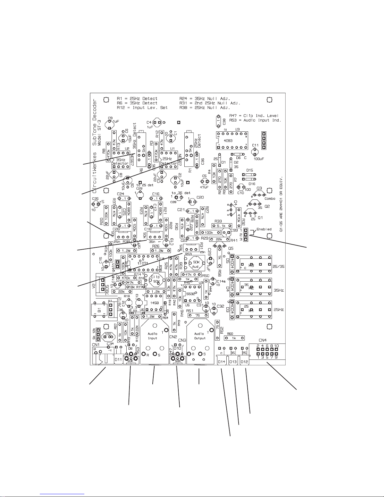
35 Hz Detect
Claibration
25 Hz Detect
Calibration
Main 25Hz
Null adjust
SUB-3 PC Board Layout
35Hz Null
adjust
Secondary
25Hz Null
adjust
Power Jack and
Power LED
Audio Out
Audio Out
Level and
Clip LED
Audio Out
Audio Out
Level and
Clip LED
Enable Mode
Jumper
Relay and Enable
connector CN4
25Hz Present LED
35Hz Present LED
25/35Hz Present LED
Page 7
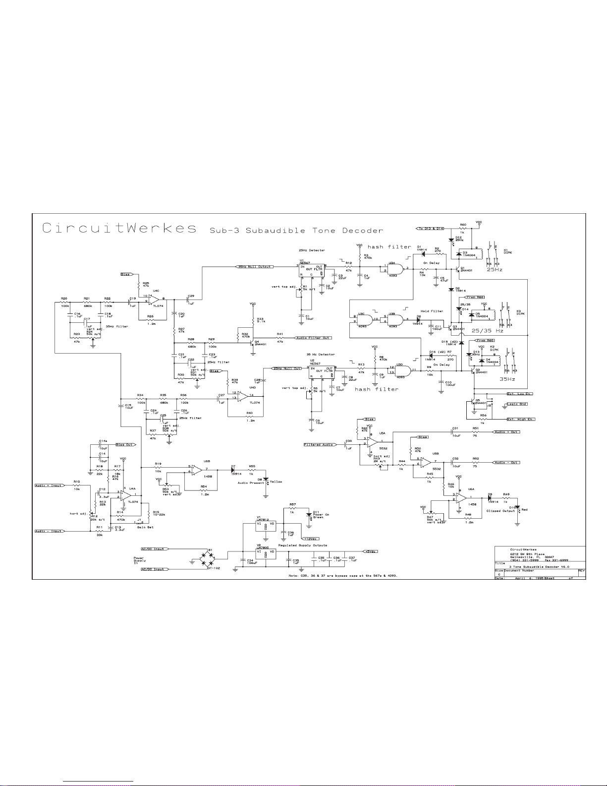
Sub-3 Subaudible Tone Decoder Schematic
Page 8
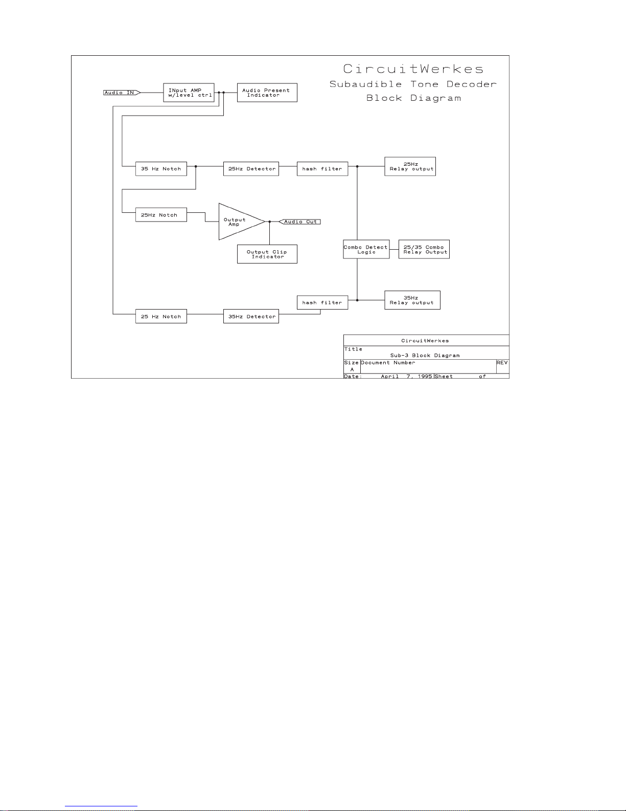
Theory of Operation
Incoming audio is buffered and level controlled by U4a and its associated components. Three nodes
are fed by this first buffer section, the input audio presence indicator , the 35Hz notch section and the
main 25Hz notch section.
The audio input presence indicator is comprised of opamp U6b (operated as a comparator),
reference-set pot R53, a yellow LED and associated components. When the audio level exceeds the
preset comparator reference level, the comparator changes states and illuminated the LED.
The 35Hz notch section is a twin-tee bridge circuit, the exact center frequency of which is set by
multiturn pot R24. Buffer U4c feeds the 25 Hz detector section and a secondary 25Hz notch filter
(of the same design) which in turn feeds the balanced output amps comprised of U5 and its associated
components. Another comparator-LED circuit hangs off the end of the output amp and is set to
illuminate when the audio output level approaches clipping.
The main 25Hz filter section is constructed just like the other two notch sections and in turn feeds the
35Hz detector section.
The outputs of the two detector sections feed through hash filters (to eliminate some extraneous
falsing). The hash filters are simple RC filters on Schmitt trigger inputs of U3a (25Hz detector) and
U3d (35Hz detector). The outputs of the hash filters feed an AND gate (U3c and U3b) directly and
the relay driver circuits for their respective relays through an RC delay filter. If both tones are
detected simultaneously , the and gate circuit fires the combo tone relay and defeats the relay drivers
of the individual tone outputs. If only a single tone is detected, its relay output folows.
Page 9

Alignment
Levels.
Audio levels can be adjusted with the front panel audio pots (Input and Output). Start with the Input
levels and feed the unit with normal program audio. Adjust the input until the input audio presence
LED flashes with about 50% duty cycle with the incoming audio. Output audio should be adjusted
for desirable levels into your console or automation.
Filters and Detectors.
The filter sections and detectors are tuned at the factory with standard reference tones and should not
need further adjustment by the user . However, if the need arises to tune these circuit sections you will
need a scope or analog audio level meter that has good display characteristics at low audio
frequencies, a signal generator or known accurate 25Hz and 35Hz signal source, and an accurate
frequency counter if your signal source is a continuously adjustable device (most are). The frequency
counter can be left hung across the signal source for fine tuning the frequency of the signals being fed
during the alignment process. The audio level of the tone source should be between -10 and 0 dBm.
If the signal is unbalanced, be sure to tie ring and sleeve on the input connector to the unbalanced
source's shield.
To Tune the filter sections set the generator or signal source for the operating frequency of the filter
being tuned and adjust the associated multiturn pot for minimum audio (the null point) at the test
point for the filter you are adjusting.
Main 25Hz filter - adjust R38 - test point is pin 3 of U2.
35 Hz filter - adjust R24 labelled "35n" - test point is U1 pin 3.
Secondary 25Hz - adjust R31 - test point is the main audio output.
The detectors should not be aligned unless the filter sections have been aligned first.
The detector alignment process is the same for both detectors. First set the signal source for the
operating frequency of the detector you will be tuning, then find the turn-on point of the detector in
each direction of rotation of the multiturn detector's alignment pot. Set the pot for half way between
thee two points.
R1 is the 25Hz detector adjustment; R6 is the 35Hz detector adjustment.
Page 10

REPAIR OR SERVICE INFORMATION
In the event of the need for service or repair, call CircuitWerkes at (352) 331-5999 or 335-6555 for
a Return Merchandise Authorization number (RMA). Then carefully package the unit along with a
note of the problem and send it to the address below. Clearly indicate the RMA number on the
outside of the box. We cannot accept returns without an RMA. Be sure to include your address (not
a PO box), telephone number and best time to call.
CirCir
cuitWcuitW
Cir
cuitW
CirCir
cuitWcuitW
A TTN: CUSTOMER SERVICE DEPT.
3716 SW 3rd Place
G AINESVILLE , FL 32607
erer
er
erer
kk
eses
k
es
kk
eses
This product is warranted against defects for two years from date of
CircuitWerkes Limited Warranty
purchase from CircuitWerkes and CircuitWerkes authorized distributors.
Within this period, we will repair it without charge for parts and labor.
Proof of purchase-date required. Warranty does not cover
transportation costs, or a product subjected to misuse, accidental
damage, alteration (except as authorized by CircuitWerkes),
improper installation, or consequential damages.
Except as provided herein, CircuitWerkes makes no warranties, express
or implied, including warranties of merchantability and fitness for a
particular purpose. Some states do not permit limitation or exclusion
of implied warranties; therefore, the aforesaid limitation(s) or
exclusion(s) may not apply to the purchaser. This warranty gives you
specific legal rights and you may also have other rights which vary from
state to state.
 Loading...