


Circuit Slices, LLC Dual Parallel VCO User Manual CS023
CS023
-UM v1
.0| www.circuitslices.com
1
The Circuit Slices Dual Parallel VCO combines two oscillators in one narrow module for
Eurorack-compatible synthesizers. The 12HP width makes it smaller than most single VCOs. It is
pre-patched, or normalled with the VCOs controlled in parallel; the FREQ knob controls both
VCOs while there are two independent fine-tune controls (FINE 1 and FINE 2). This allows
overall pitch adjustment while retaining an interesting interval or modulation effect between
the two VCOs. You may also supply separate pitch control voltages to each VCO individually, but
the PWM and FM inputs always go to both. The VCOs are high quality, matched-transistor,
temperature-compensated type with triangle, sawtooth and pulse outputs. It makes cool thick
sounds for just one narrow module.
Specifications for the Dual Parallel VCO, part number CS023
Eurorack format
Standard one-volt-per-octave pitch control
Over 10V control range
Frequency range for VCO 1 and VCO 2: 8Hz to over 32KHz
Frequency range of VCO 2 with the range switch set to “low”: 4Hz to over 16KHz
Typical pitch tracking errors for 10 octaves:
• 0.00% error for first 4 octaves
• Less than 0.5% error for next 4 octaves
• Less than 4% error up to the 10th octave
Outputs: Sawtooth, Triangle, Pulse
Output levels: 10Vp-p (+/- 5V)

Circuit Slices, LLC Dual Parallel VCO User Manual CS023
CS023
-UM v1
.0| www.circuitslices.com
2
Power: +12VDC @ 52mA, -12DC @ 52mA
Reverse power protected
12 HP, Depth from front panel: 1.55”
Features for the Dual Parallel VCO, part number CS023
• Narrow width
• Incredibly fat sounds for one small module
• Modern SMT design for small footprint and decreased cost
High quality VCOs:
• Matched-transistor pair oscillator design (triangular-type core)
• VCO cores use high-performance, low noise, zero drift, op-amps (OPA series or similar)
• Each VCO is temperature-compensated (TEMPCO) for frequency stability
• Oscillators track up to 10 octaves
Six inputs:
• 1V / octave 1 for VCO 1
• 1V / octave 2 for VCO 2*
• FM 1, 2 frequency modulation for both VCOs
• PWM 1, 2 pulse with modulation for both VCOs
• Sync 1
• Sync 2
*Note that a signal or CV patched to VCO 2 is “Normalled” with VCO 1
CV patched into “1V / oct 2” only, controls both VCOs
CV patched into “1V / oct 1” separates the two VCOs into independently controllable
oscillators
Six outputs:
• 2 Triangle,
• 2 Sawtooth,
• 2 Pulse
(Outputs can be passively summed using “stackable” cables or a passive “multiple”)
Controls:
• FREQ knob controls course pitch for both VCOs
• FINE 1 and TUNE 2 knobs fine-tune the VCO pitch separation over two octaves
(Adjust FINE controls for a given interval and it tracks as the FREQ control is adjusted)
• PULSE WIDTH knob controls the initial pulse width of the pulse output
• PWM knob controls the amount of pulse width modulation applied to both VCOs
• FM knob controls the amount of modulation (lin or exp) to both VCOs

Circuit Slices, LLC Dual Parallel VCO User Manual CS023
CS023
-UM v1
.0| www.circuitslices.com
3
• VCO 2 RANGE switch lowers the range of VCO 2 for greater separation between
oscillators (VCO 2 can be adjusted to act as a VC-LFO)
• FM MODE switch selects between Linear and Exponential frequency modulation
Installation
The module is ready to install in your Eurorack case. Simply mount the panel using the supplied
screws and route the ribbon-cable power connector to your power bus.
Be careful making the connection to your power bus and double check your connection before
applying power. The red stripe on the ribbon cable must be toward the -12V pin on the power
bus. While this module is protected from reverse voltage, it is still well worth taking
precautions to protect your system.
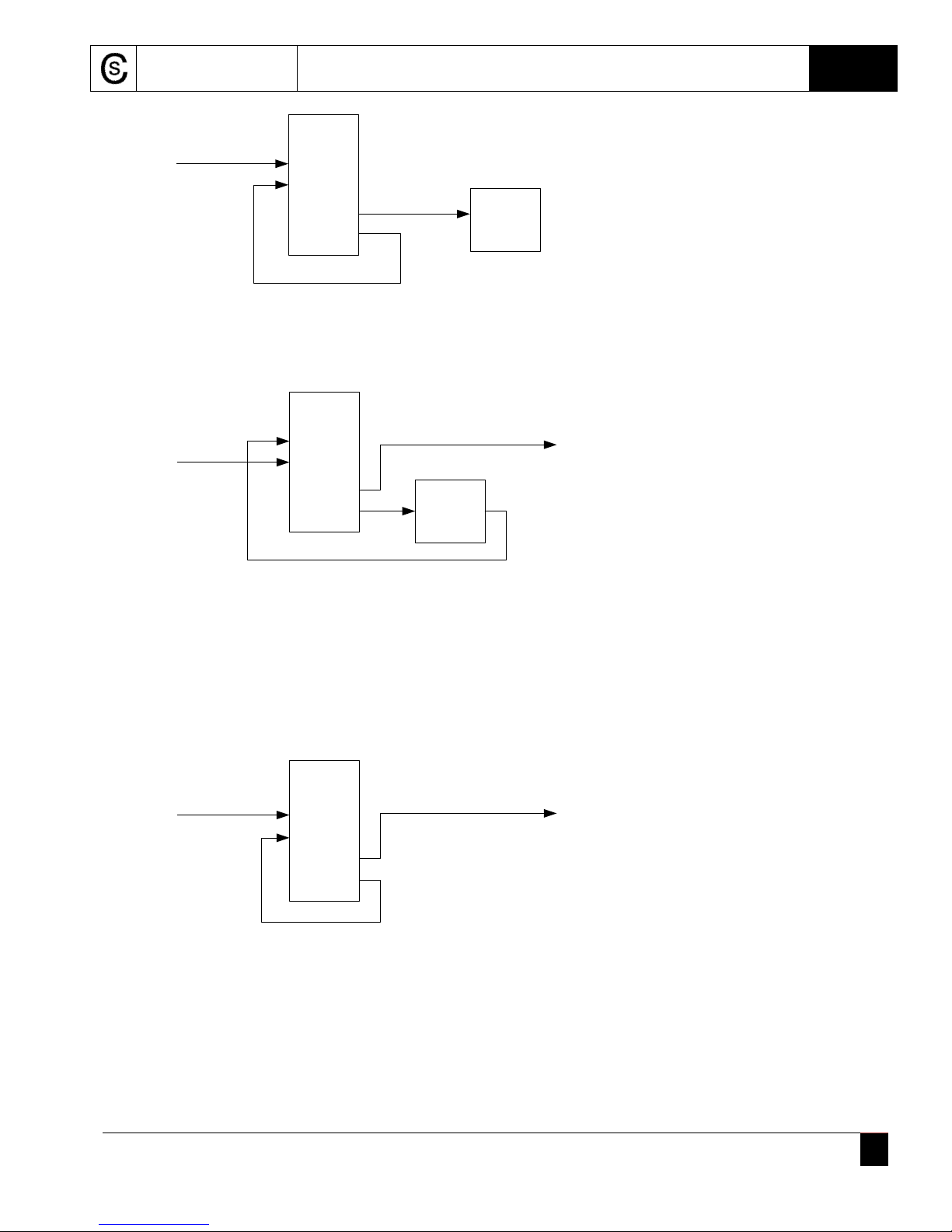
Patch Ideas
Patch a CV from a keyboard, sequencer or MIDI-CV to the “1V / oct 2” input. This will route the
CV to both internal VCOs. Adjust the FINE controls for unison, octave, 1/5th, etc. If patching to
the two inputs of a ring modulator, try using the triangle outputs from the Dual VCO.
DP-VCO
KB CV
Sequencer CV
1v / oct 1
1v / oct 2
Saw 1
Triangle 2
mixer
VCF
VCA
Ring Mod
Try using the VCOs separately, patching a keyboard CV to input 1 and a sequencer CV to input
2. Use a sawtooth output for the “lead keyboard” sound and set the VCO 2 RANGE switch to
low for a bass line from the sequencer. Also, try adding an external LFO output to the FM 1, 2
input with the FM MODE switch set to “lin” for vibrato to both VCOs.
Circuit Slices, LLC Dual Parallel VCO User Manual CS023
CS023
-UM v1
.0| www.circuitslices.com
4
DP-VCO
KB CV
1v / oct 1
PWM 1, 2
Pulse 1
Triangle 2
mixer
VCF
VCA
Ring Mod
Use the VCO 2 output to modulate the pulse width of VCO 1.
DP-VCO
Output
KB CV
1V / oct 1
1V / oct 2
Triangle 1
Triangle 2
VCA or
Attenuator
Try modulating one VCO with the output of the other VCO. Remember that the “FM 1, 2” input
will control both VCOs, but you can still send one VCO output to the other VCO independently,
by using the “1V / oct” input. Try using a VCA or attenuator to control the level of the signal
going to the modulated VCO. An ADSR patched to the VCA will control the percent of
modulation over time.
DP-VCO
KB CV
1V / oct 1
1V / oct 2
SYNC 1
Triangle 1
Pulse 2
Output
You can get some very interesting sounds using the SYNC inputs. Here the VCO 2 output hardsynchronizes VCO 1. Note that the input control voltage is going to both VCOs. Carefully adjust
the TUNE controls and apply just a little LIN FM, with some portamento from your keyboard, to
make some almost vowel-like sounds. Pretty cool for such a simple patch!
Of course this just scratches the surface of patches you can try with this module. Have fun and
let us know of any interesting patches that you are willing to share.

Circuit Slices, LLC Dual Parallel VCO User Manual CS023
CS023
-UM v1
.0| www.circuitslices.com
5
Calibration
The two VCOs are on separate PCBs that plug into 26-pin header sockets. Each board has three
multi-turn trimmers. P1 is adjusted for a 1-volt-per-octave pitch response. P2 is used for highfrequency tracking, if needed. Finally, P3 is used to adjust the shape of the sawtooth output.
This module ships factory calibrated. If it becomes necessary to adjust one or both oscillators, a
frequency counter and oscilloscope will be needed. Adjust P1 for a one octave shift from 100Hz
to 200Hz for a 1 volt control voltage change. Then adjust the FREQ control to 2000Hz and make
an increase in the CV by 1 volt for a change to 4000Hz. Adjust P2 if necessary. After the high
frequency tracking adjustment, you may need to re-adjust P1. You may have to compromise a
little to get it tuned over the entire range. The oscillator pitch may become “sharp” as you go
above the musically useful range (8 kHz) but will still respond, increasing up to and above the
hearing range. Adjust P3 so that the sawtooth output displays a smooth ramp on your
oscilloscope.
The FINE controls were designed to give the most range and still retain enough sensitivity to
tune an interval between the two VCOs. So, you may find the FINE controls a little more
‘course’ than you would expect, but still pretty easy to adjust.
Output Impedance
Each output includes a series 1K ohm resistor, like classic VCO designs. While not really
necessary for output protection with today’s op-amps, the resistors make it possible to
passively add two signals together using “stackable” cables or a passive “multiple”. This means
you can patch two outputs into a single VCF or VCA input, without needing to use a mixer. Try
combining different waveforms for interesting timbers.
This module is warranted for one year with parts, under normal use – not including the
application of reverse or over-voltage power by customer. Return shipping to Circuit Slices
from customer not included. Return to Circuit Slices, LLC for repairs. Circuit Slices, LLC reserves
the right to replace the module if necessary. Please keep your receipt / packing slip for
warranty information.
Circuit Slices, LLC
10028 Windjammer Trail
Aurora, OH 44202
 Loading...