

Page 1

1
Tacholink Professional Installation Guide
CL-T5-001
Version: 1.7
Date: 9/02/2015
Circuitlink Pty Ltd, ABN 80 057 670 505, 7/30 Foundry Road, Seven Hills NSW 2147 Australia T: +61 2 9624 1922 F: +61 2 9624 1911
E: [email protected] Document Status: Final. Publish Date: 9/02/2015
CIRCUITLINK.COM.AU
Page 2

2
Legal Notice
This document contains confidential and proprietary information of Circuitlink and is for the use of and disclosure to
employees, Circuitlink Authorized Service Providers and their employees.
The use of this document by or disclosure of this document to, any other person or entity is strictly prohibited.
Circuitlink Pty Ltd, ABN 80 057 670 505, 7/30 Foundry Road, Seven Hills NSW 2147 Australia T: +61 2 9624 1922 F: +61 2 9624 1911
E: [email protected] Document Status: Final. Publish Date: 9/02/2015
CIRCUITLINK.COM.AU
Page 3

3
Contents
Legal Notice .......................................................................................................................................................................... 2
Figures .................................................................................................................................................................................. 4
Safety Warnings .................................................................................................................................................................... 5
Installation ......................................................................................................................................................................... 5
FCC RF Radiation Exposure Statement ........................................................................................................................... 5
FCC Warning Statement ................................................................................................................................................... 6
Australian Communications and Media Authority Notice. ................................................................................................. 6
Modifications ..................................................................................................................................................................... 6
Specifications ........................................................................................................................................................................ 6
Electrical ........................................................................................................................................................................... 6
Enclosure .......................................................................................................................................................................... 7
Connecting to the Tacholink 5 ............................................................................................................................................... 7
Blunt Cut Hardwired .......................................................................................................................................................... 8
Samtec 20 pin (Blunt Cut) ............................................................................................................................................... 10
Samtec 40 Pin (Blunt Cut) .............................................................................................................................................. 11
T5 Standard External OBDII (PN 3400123) .................................................................................................................... 12
T5 Standard J1939 + Power (PN 3400124) .................................................................................................................... 13
T5 Power Loom (PN 3400133) ....................................................................................................................................... 13
T5 CAN Bus Loom (PN 3400134) ................................................................................................................................... 14
Remote Accelerometer ........................................................................................................................................................ 14
Installation ........................................................................................................................................................................... 15
Under Seat Mounting ...................................................................................................................................................... 15
Cabinet / Panel Mounting ................................................................................................................................................ 15
Dashbox .......................................................................................................................................................................... 15
T5 Standard External OBDII (PN 3400123) .................................................................................................................... 15
Connecting the T5 ............................................................................................................................................................... 16
Removing the Face Plate .................................................................................................................................................... 16
Loading Fleet Configuration File ......................................................................................................................................... 17
Event Data Recorder ...................................................................................................................................................... 17
Remote Accelerometer ................................................................................................................................................... 17
Troubleshooting .................................................................................................................................................................. 18
Circuitlink Configuration Utility ........................................................................................................................................ 18
LED Activity .................................................................................................................................................................... 21
FCC Approved Antennas .................................................................................................................................................... 22
MA600 ............................................................................................................................................................................ 22
MA206 ............................................................................................................................................................................ 22
ANT-2.4-CW-RH ................................................................................................................................ ............................. 23
Contact Information ............................................................................................................................................................. 24
Revision History .................................................................................................................................................................. 25
Circuitlink Pty Ltd, ABN 80 057 670 505, 7/30 Foundry Road, Seven Hills NSW 2147 Australia T: +61 2 9624 1922 F: +61 2 9624 1911
E: [email protected] Document Status: Final. Publish Date: 9/02/2015
CIRCUITLINK.COM.AU
Page 4

4
Figures
Figure - Cinch ModICE LE Enclosure Dimensions ............................................................................................................... 7
Figure - 3400124 ................................................................................................................................................................ 13
Figure - 3400133 ................................................................................................................................................................ 13
Figure - 3400134 ................................................................................................................................................................ 14
Figure - Locating the T5 when there are multiple COM ports ............................................................................................. 18
Figure - Circuitlink Configuration Utility during a live connection ................................................................ ........................ 19
Circuitlink Pty Ltd, ABN 80 057 670 505, 7/30 Foundry Road, Seven Hills NSW 2147 Australia T: +61 2 9624 1922 F: +61 2 9624 1911
E: [email protected] Document Status: Final. Publish Date: 9/02/2015
CIRCUITLINK.COM.AU
Page 5

5
Safety Warnings
Caution
The T5 must be mounted at least 25cm away from any transmitting antennas.
Do Not Mount the T5 Unit :
– To Air Lines or any vehicle cabling
– In direct exposure to the elements
– In excessive heat areas (exhaust manifolds, etc.)
– In excessive cold areas (refrigeration units)
– In high vibration areas (engine compartments, transmission)
– Near corrosive fluids and gases (acids, petroleum)
– In direct exposure to water
– In areas where excessive dust is present
Caution
Vehicles equipped with air bags.
An air bag inflates with great force. Do not place objects, including this device, in the area over the air bag or
in the air bag deployment area. Serious injury could result if in-vehicle wireless equipment is incorrectly
installed and the air bag inflates.
Installation
The T5 unit must be installed by a professional installer familiar with vehicle systems and RF signals. Incorrect installation
may interfere with vehicle safety systems such as ABS, stability control and airbags or engine management CAN bus
signalling.
The T5 Unit must be mounted in a secure and hidden location to deter driver tampering.
When mounting the T5 Unit, find a suitable location that will not interfere with the safe operation of the vehicle (e.g.,
braking, clutch operation, or other electronic equipment).
The T5 Unit must be secured in the vehicle. Use tie wraps, screws, nut/bolts. The use of double sided tape to secure the
unit is not recommended, the T5 unit needs to be firmly fixed to a flat surface to allow the correct operation of the internal
accelerometer with all axes’ square to the direction of travel.
FCC RF Radiation Exposure Statement
This transmitter must not be co-located or operating in conjunction with any other antenna or transmitter.
This equipment complies with FCC RF radiation exposure limits set forth for an uncontrolled environment.
This equipment should be installed and operated with a minimum distance of 25 centimeters between the radiator and
your body.
Circuitlink Pty Ltd, ABN 80 057 670 505, 7/30 Foundry Road, Seven Hills NSW 2147 Australia T: +61 2 9624 1922 F: +61 2 9624 1911
E: [email protected] Document Status: Final. Publish Date: 9/02/2015
CIRCUITLINK.COM.AU
Page 6
6
FCC Warning Statement
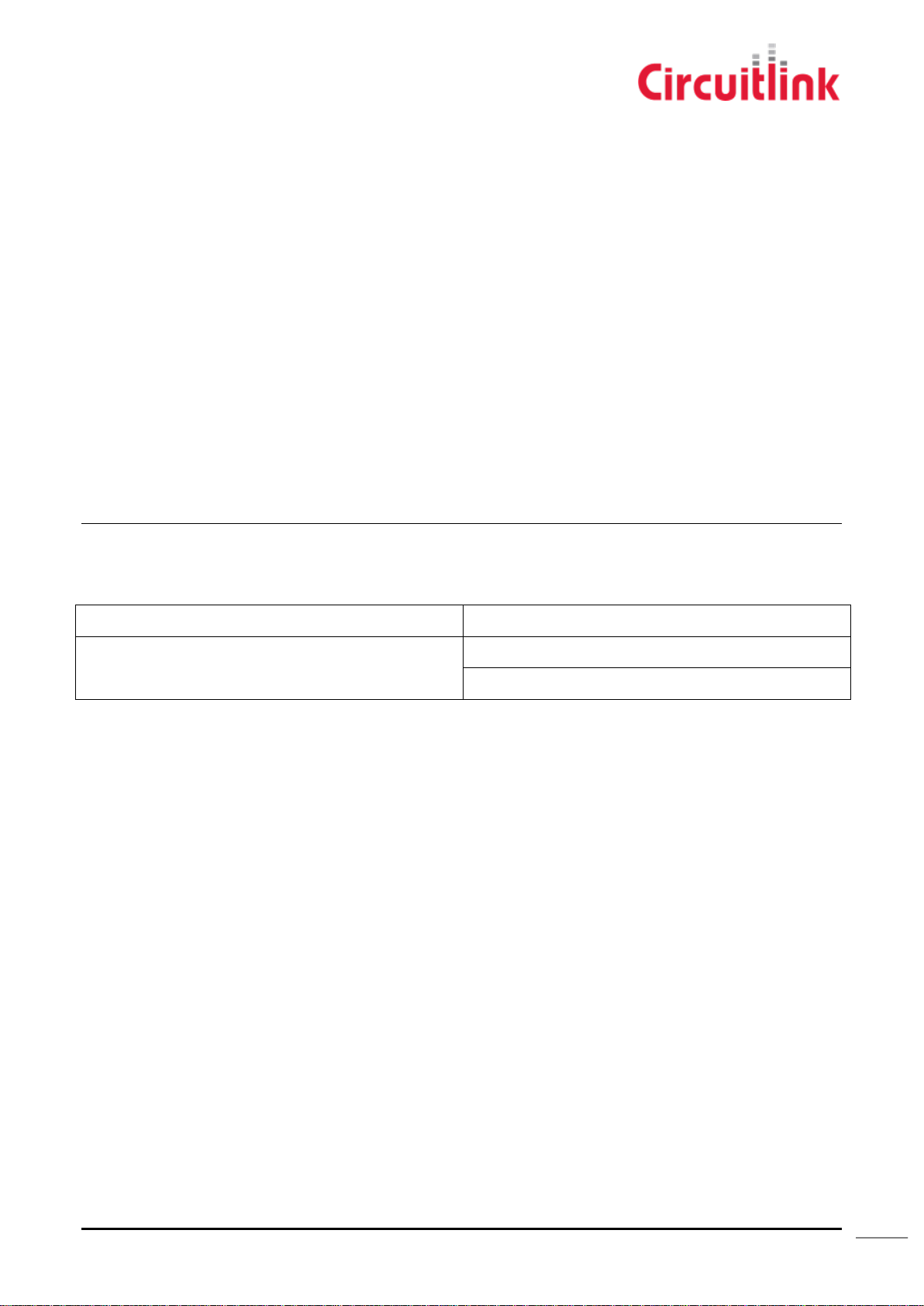
Input Voltage
9-32VDC
Current
0.21A at 9V
0.11A at 32V
This equipment has been tested and found to comply with the limits for a Class A digital device, pursuant to part 15 of the
FCC Rules. These limits are designed to provide reasonable protection against harmful interference when the equipment
is operated in a commercial environment. This equipment generates, uses, and can radiate radio frequency energy and, if
not installed and used in accordance with the instruction manual, may cause harmful interference to radio
communications. Operation of this equipment in a residential area is likely to cause harmful interference in which case the
user will be required to correct the interference at his own expense.
Australian Communications and Media Authority Notice.
Warning
This is a class A product. In a domestic environment this product may cause radio interference in which case the user may
be required to take adequate measures.
Modifications
This product does not contain any user serviceable components. Any unauthorised product changes or modifications will
invalidate warranty and all applicable regulatory certifications and approvals.
Specifications
Electrical
The Tacholink 5 is fitted with internal self-resetting thermal fuses to limit current in the event of a fault. To protect the
vehicle against faults in the external wiring, the use of a 5A slow-blow fuse is recommended.
Circuitlink Pty Ltd, ABN 80 057 670 505, 7/30 Foundry Road, Seven Hills NSW 2147 Australia T: +61 2 9624 1922 F: +61 2 9624 1911
E: [email protected] Document Status: Final. Publish Date: 9/02/2015
CIRCUITLINK.COM.AU
Page 7
7
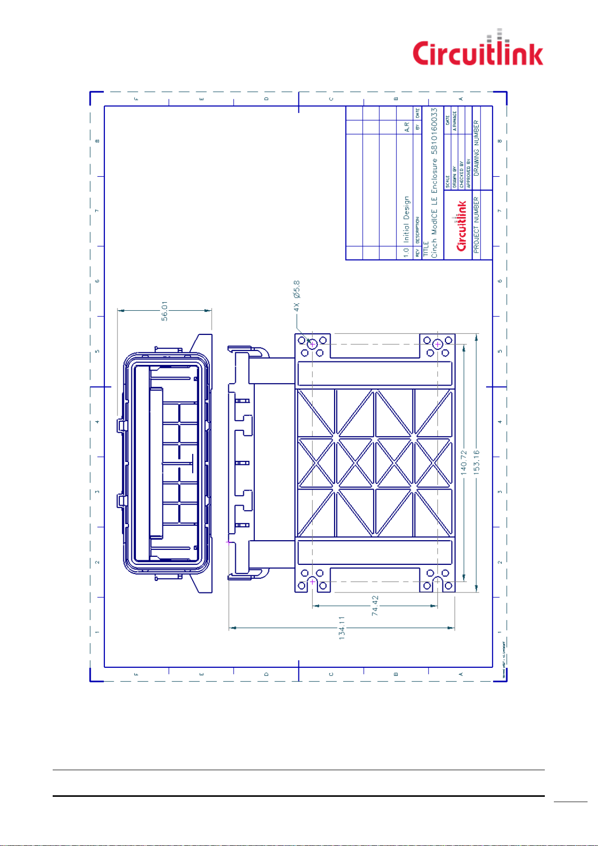
Enclosure
Figure 1 - Cinch ModICE LE Enclosure Dimensions
Connecting to the Tacholink 5
Circuitlink Pty Ltd, ABN 80 057 670 505, 7/30 Foundry Road, Seven Hills NSW 2147 Australia T: +61 2 9624 1922 F: +61 2 9624 1911
E: [email protected] Document Status: Final. Publish Date: 9/02/2015
CIRCUITLINK.COM.AU
Page 8
8
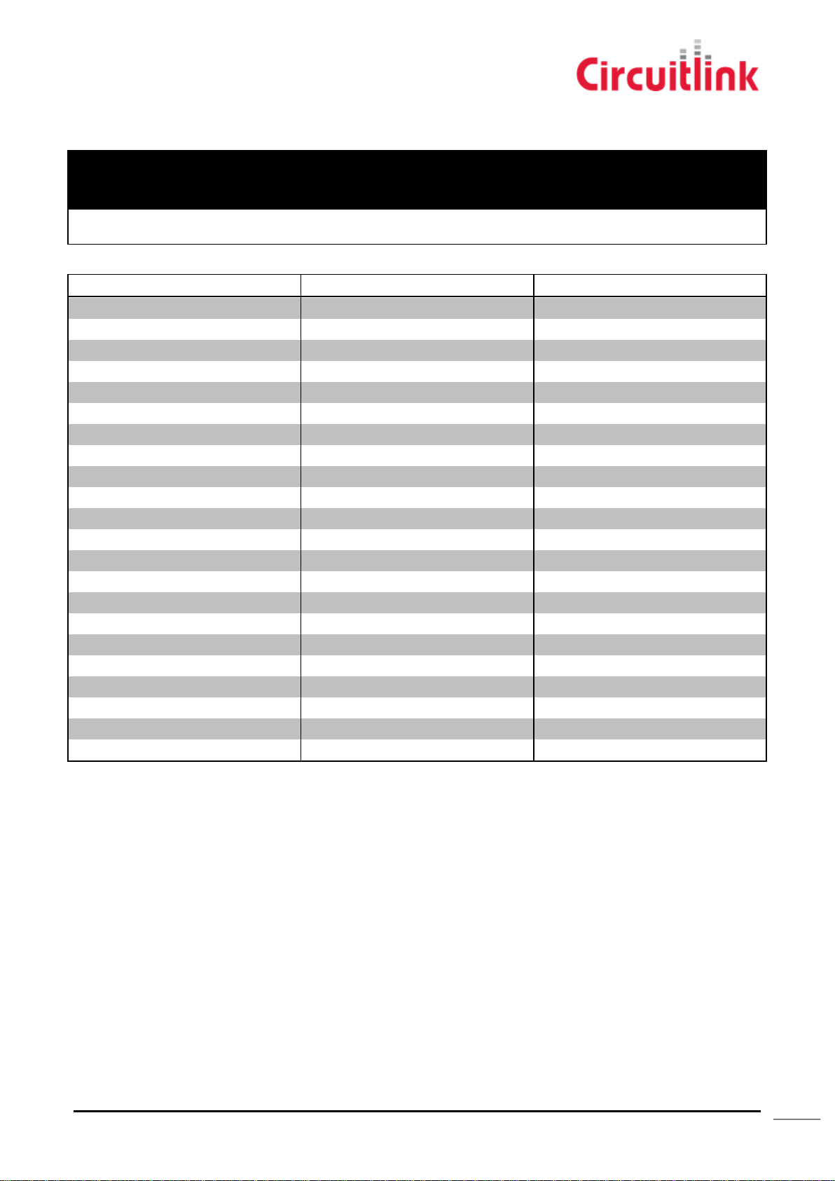
Blunt Cut Hardwired
NEAREST AWG
NO. OF CORES
CONDUCTIOR
NO/DIA (MM)
INSULATION
THICKNESS (mm)
NOM. DIA (mm)
28
20
7/0.2 TC
0.2
7
Signal
Colour
Installer Notes
Shield
NOT CONNECTED
GND
GREEN
PWR IN
RED
Ignition
YELLOW
Speed
WHITE
RPM
BLUE
PWR Out
BLACK
GND
BROWN
PWM 1
PURPLE
PWM 2
ORANGE
PWM 3
PINK
PWM 4
TURQUOISE
1WIRE
GREY
RS485 RxA
RED / BLUE
RS485 TxA
GREEN / RED
RS485 RxB
YELLOW / RED
RS485 TxB
WHITE / RED
RS485 BR
RED / BLACK
CAN0V
RED/BROWN
CANL
YELLOW/BLUE
CANH
WHITE/BLUE
CANS
NOT CONNECTED
Cable 1 (3400163)
Circuitlink Pty Ltd, ABN 80 057 670 505, 7/30 Foundry Road, Seven Hills NSW 2147 Australia T: +61 2 9624 1922 F: +61 2 9624 1911
E: [email protected] Document Status: Final. Publish Date: 9/02/2015
CIRCUITLINK.COM.AU
Page 9
9
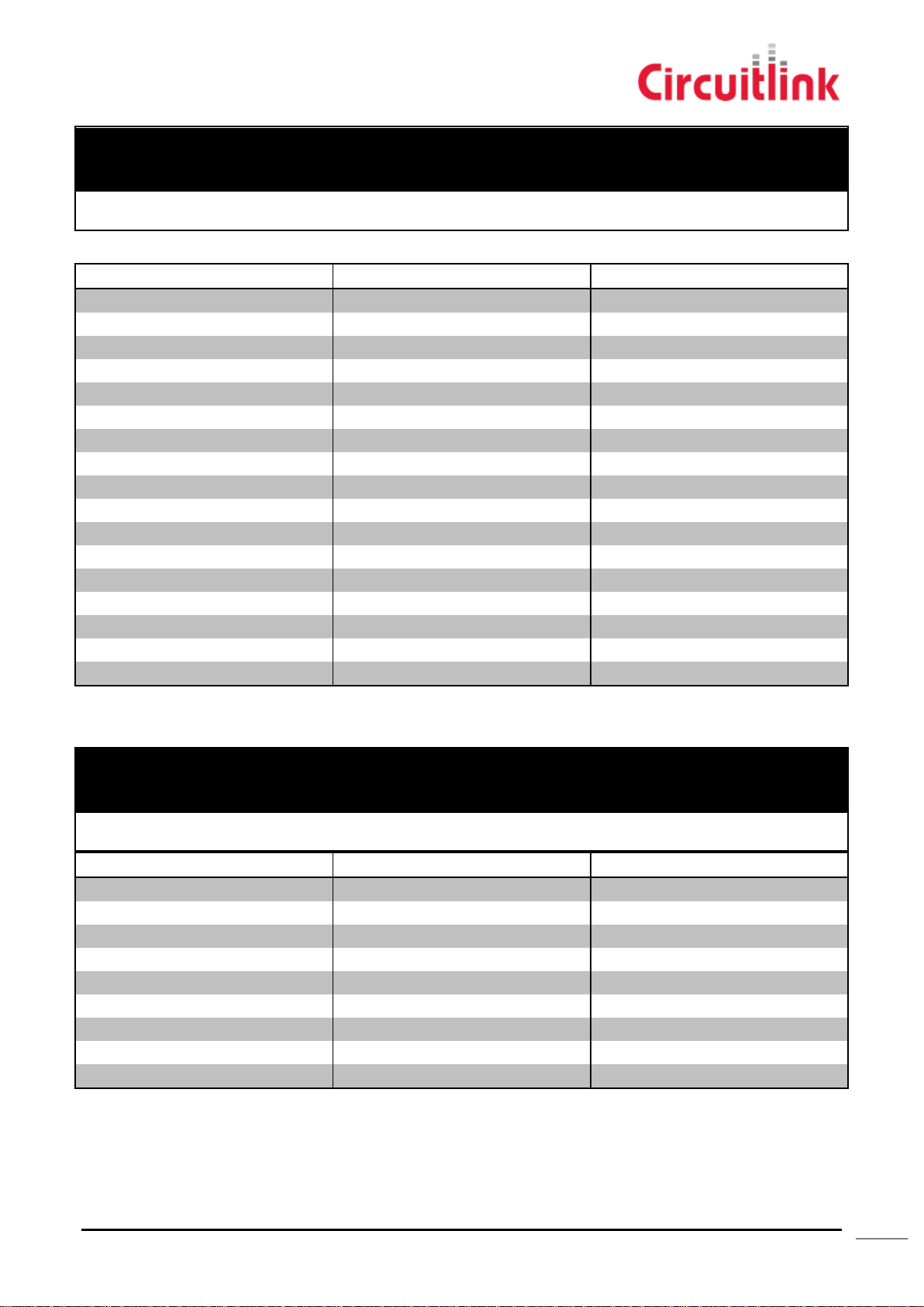
Cable 2 (3400164)
NEAREST AWG
NO. OF CORES
CONDUCTIOR
NO/DIA (MM)
INSULATION
THICKNESS (mm)
NOM. DIA (mm)
28
20
7/0.2 TC
0.2
7
Signal
Colour
Installer Notes
ANALOG IN 1
GREEN
ANALOG IN 2
RED
ANALOG IN 3
YELLOW
ANALOG IN 4
WHITE
ANALOG IN 5
BLUE
ANALOG IN 6
BLACK
ANALOG IN 7
BROWN
ANALOG IN 8
PURPLE
RELAY 1
ORANGE
RELAY 2
PINK
RELAY 3
TURQUOISE
RELAY 4
GREY
RS232 TX
RED / BLUE
RS232 RX
GREEN / RED
RS232 RTS
YELLOW / RED
RS232 CTS
WHITE / RED
GND
RED / BLACK
NEAREST AWG
NO. OF CORES
CONDUCTIOR
NO/DIA (MM)
INSULATION
THICKNESS (mm)
NOM. DIA (mm)
28
20
7/0.2 TC
0.2
7
Signal
Colour
Installer Notes
ADDITIONAL INPUT 1
GREEN
ADDITIONAL INPUT 2
RED
ADDITIONAL INPUT 3
YELLOW
ADDITIONAL INPUT 4
WHITE
ADDITIONAL INPUT 5
BLUE
CANSHIELD/J1939
BLACK
CANGND/J1939
BROWN
CANL/J1939
PURPLE
CANH/J1939
ORANGE
Cable 3 (3400165)
Circuitlink Pty Ltd, ABN 80 057 670 505, 7/30 Foundry Road, Seven Hills NSW 2147 Australia T: +61 2 9624 1922 F: +61 2 9624 1911
E: [email protected] Document Status: Final. Publish Date: 9/02/2015
CIRCUITLINK.COM.AU
Page 10
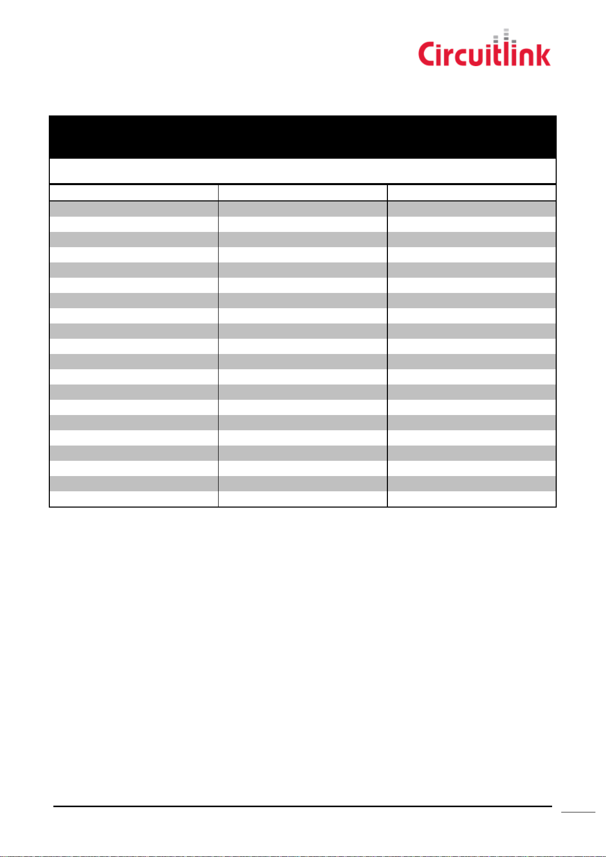
10
NEAREST AWG
NO. OF CORES
CONDUCTIOR
NO/DIA (MM)
INSULATION
THICKNESS (mm)
NOM. DIA (mm)
28
20
7/0.2 TC
0.2
7
Signal
Colour
Installer Notes
Ground
BLACK
Power In
BROWN
Ignition
RED
Speed
ORANGE
RPM
YELLOW
Power Out
GREEN
Ground
BLUE
PWM 1
PURPLE
PWM 2
GREY
PWM 3
WHITE
PWM 4
PINK
1 Wire
LIGHT GREEN
RS485 RxA
BLACK / WHITE
RS485 TxA
BROWN / WHITE
RS485 RxB
RED / WHITE
RS485 TxB
ORANGE / WHITE
RS232 Br
GREEN / WHITE
CAN 0V
BLUE / WHITE
CAN Low
PURPLE / WHITE
CAN High
RED / BLACK
Samtec 20 pin (Blunt Cut)
Circuitlink Pty Ltd, ABN 80 057 670 505, 7/30 Foundry Road, Seven Hills NSW 2147 Australia T: +61 2 9624 1922 F: +61 2 9624 1911
E: [email protected] Document Status: Final. Publish Date: 9/02/2015
CIRCUITLINK.COM.AU
Page 11
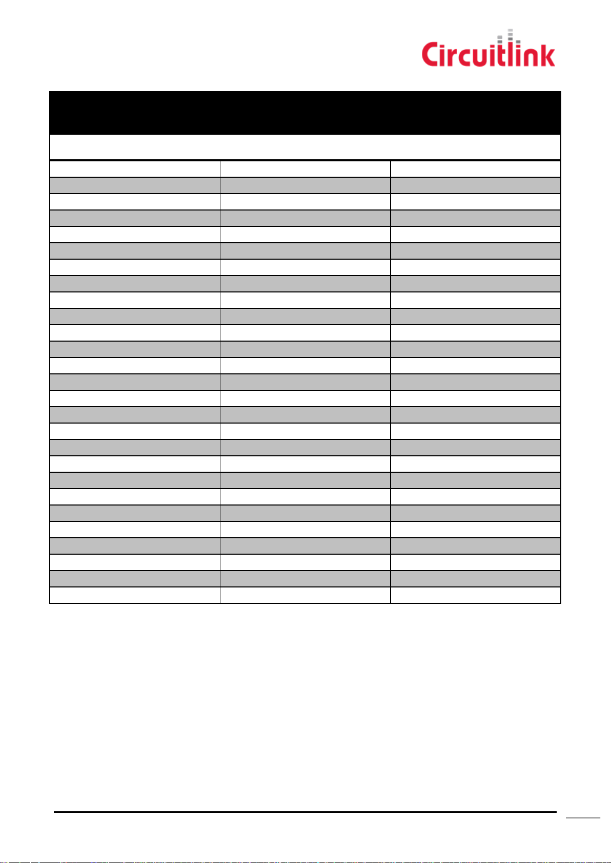
11
Samtec 40 Pin (Blunt Cut)
NEAREST AWG
NO. OF CORES
CONDUCTIOR
NO/DIA (MM)
INSULATION
THICKNESS (mm)
NOM. DIA (mm)
28
40
7/0.2 TC
0.2
7
Signal
Colour
Installer Notes
Analog Input 1
BLACK
Analog Input 2
BROWN
Analog Input 3
RED
Analog Input 4
ORANGE
Analog Input 5
YELLOW
Analog Input 6
GREEN
Analog Input 7
BLUE
Analog Input 8
PURPLE
Relay 1
GREY
Relay 2
WHITE
Relay 3
PINK
Relay 4
LIGHT GREEN
RS232 TX
BLACK/WHITE
RS232 RX
BROWN/WHITE
RS232 RTS
RED/WHITE
RS232 CTS
ORANGE/WHITE
Ground
GREEN/WHITE
Additional Input 1
LIGHT BLUE/BLUE
Additional Input 2
LIGHT BLUE/GREEN
Additional Input 3
GRAY/RED
Additional Input 4
GRAY/GREEN
Additional Input 5
PURPLE/BLACK
CAN SHEILD/J1939
BLUE/BLACK
CAN GROUND/J1939
LIGHT GREEN/BLACK
CAN LOW/J1939
LIGHT GREEN/RED
CAN HIGH/J1939
LIGHT GREEN/BLUE
Wires 18-31 are not connected.
Circuitlink Pty Ltd, ABN 80 057 670 505, 7/30 Foundry Road, Seven Hills NSW 2147 Australia T: +61 2 9624 1922 F: +61 2 9624 1911
E: [email protected] Document Status: Final. Publish Date: 9/02/2015
CIRCUITLINK.COM.AU
Page 12
12
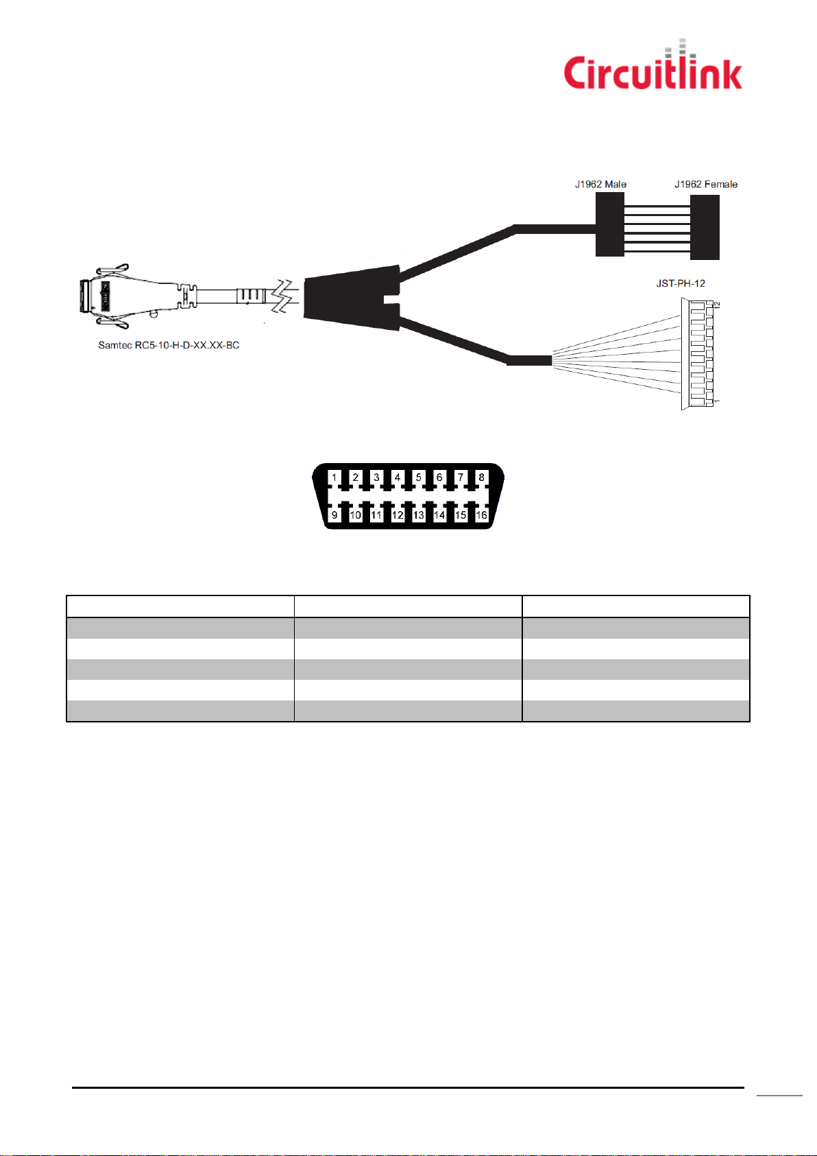
T5 Standard External OBDII (PN 3400123)
Signal
Terminal
Installer Notes
Ground
4 (B)
Power In
16 (A)
CAN GROUND
5 (C)
CAN LOW
14 (B)
CAN HIGH
6 (A)
Figure 2 - 3400123
J1962 Male + Female
Both Male and Female connectors have the same pin outs.
JST-PH-12
The JST-PH-12 connector is used for attaching the Dashbox (PN 5060107) to the T5.
Circuitlink Pty Ltd, ABN 80 057 670 505, 7/30 Foundry Road, Seven Hills NSW 2147 Australia T: +61 2 9624 1922 F: +61 2 9624 1911
E: [email protected] Document Status: Final. Publish Date: 9/02/2015
CIRCUITLINK.COM.AU
Page 13
13
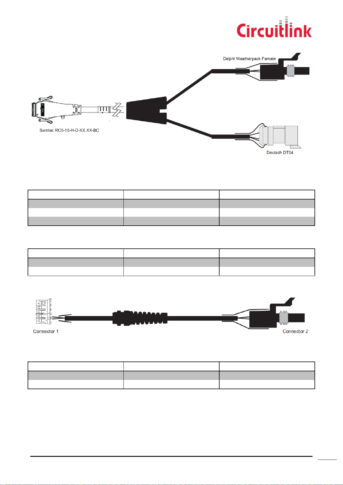
T5 Standard J1939 + Power (PN 3400124)
Signal
Terminal
Installer Notes
CAN GROUND/J1939
C
CAN LOW/J1939
B
CAN HIGH/J1939
A
Signal
Terminal
Installer Notes
Ground
B
Power In
A
Signal
Terminal
Installer Notes
Ground
B
Power In
A
Figure 3 - 3400124
Deutsch DT04
Delphi Weatherpack 2 Cavity Female
T5 Power Loom (PN 3400133)
Figure 4 - 3400133
Delphi Weatherpack 2 Cavity Female
Circuitlink Pty Ltd, ABN 80 057 670 505, 7/30 Foundry Road, Seven Hills NSW 2147 Australia T: +61 2 9624 1922 F: +61 2 9624 1911
E: [email protected] Document Status: Final. Publish Date: 9/02/2015
CIRCUITLINK.COM.AU
Page 14
14
T5 CAN Bus Loom (PN 3400134)
Signal
Terminal
Installer Notes
CAN GROUND/J1939
C
CAN LOW/J1939
B
CAN HIGH/J1939
A
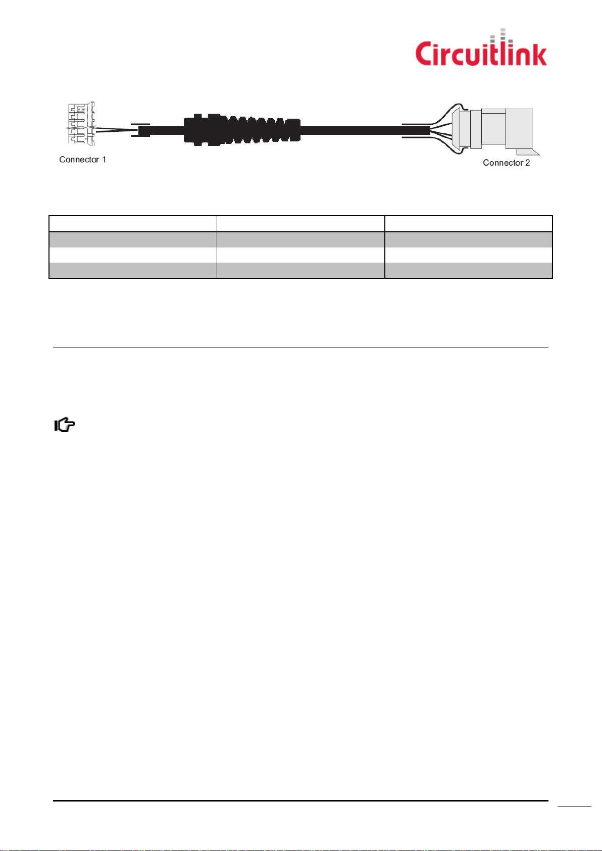
The Tacholink T5 Remote accelerometer acts as a transducer; sending all of it’s information across the
CANBus network to other device. The T5 RA does not store data or broadcast it wirelessly
Figure 5 - 3400134
Deutsch DT04
Remote Accelerometer
The Tacholink T5 Remote Accelerometer uses the same hardware platform as the Tacholink T5 EDR. Mount the T5 RA to
the vehicle using the same method as the T5 EDR. Both devices use the same power and J1939 connectors
Circuitlink Pty Ltd, ABN 80 057 670 505, 7/30 Foundry Road, Seven Hills NSW 2147 Australia T: +61 2 9624 1922 F: +61 2 9624 1911
E: [email protected] Document Status: Final. Publish Date: 9/02/2015
CIRCUITLINK.COM.AU
Page 15

15
Installation
To make full use of the internal accelerometer and gyroscope, the T5 must be firmly mounted with any of its axis
perpendicular to the direction of travel.
Caution
- Care should be taken when drilling into the floor of any vehicle as there may be
wiring or parts on the other side.
- When mounting on the driver’s side of the vehicle, it is extremely important to
ensure that the T5 is secured and cannot interfere with the safe operation of the
vehicle
- Do not expose the T5 or any of its peripherals to temperatures outside of 0°C -
80°C
Under Seat Mounting
Care should be taken when securing the T5 under seating in vehicles. Make sure the unit and its cables are properly
mounted away from any passengers and moving parts.
Cabinet / Panel Mounting
Although we design our equipment to operate in IP rated environments, we recommend when the unit is not installed
within the cabin of a vehicle that it be placed in a protected area. Avoid mounting equipment and cabling where it may
come in contact with moving parts and liquids as it will reduce its lifespan and reliability.
Different design configurations will change the IP rating depending on the front panel connectors. For more information,
contact Circuitlink.
Firmly secure the unit with bolts M5 or equivalent, using washers to distribute force evenly. Cable ties may be used for
temporary mounting and should be firmly tightened. Do not use double sided tape or any permanent adhesives.
Dashbox
Secure the Dashbox unit within the reach of the operator careful for it not to interfere with the operation of the vehicle.
Avoid placing the Dashbox where it could be exposed to weather as it does not have the same protection as the EDR.
T5 Standard External OBDII (PN 3400123)
The J1962 interconnect harness is designed to integrate with the existing diagnostic port and piggyback off it.
1. Locate and unscrew the existing connector from its mounting position. Typically it will be located within 1m of the
drivers position however may differ based on the make and model.
2. Connect the wiring assembly to the vehicles socket and mount the piggyback extension in the existing position.
3. Secure the connection between the vehicles J1962 socket and the harness by using a cable tie around the
housings.
4. Tidy cabling by securing excess wires away, careful not to kink or allow them to become tangled.
Circuitlink Pty Ltd, ABN 80 057 670 505, 7/30 Foundry Road, Seven Hills NSW 2147 Australia T: +61 2 9624 1922 F: +61 2 9624 1911
E: [email protected] Document Status: Final. Publish Date: 9/02/2015
CIRCUITLINK.COM.AU
Page 16
16
Connecting the T5
Caution
- The vehicle should be turned off when disconnecting any connectors on the T5
- Ensure when inserting the Samtec connector it is plugged in straight to avoid damaging the
fine pitched pins within the connector.
Warning
Only use cable assemblies described in this guide. Using assemblies for other models may damage the unit
and other equipment on the vehicle.
Warning
Do not place the PCB on any conductive or wet surfaces.
Where possible, follow steps to protect against ESD damage.
Improper removal of the face plate will compromise its IP rating and reliability of the device
1. Attach and firmly tighten the SMA connectors for the GPS, GSM and WIFI antennas.
When antennas are not in use it is recommended to keep the antenna attached or use (PN 3400139 - SMA plug cap)
to protect the connector from dust and water.
2. With power to the unit disconnected, connect the I/O cables from the unit to the vehicle.
Removing the Face Plate
For any reason you are required to remove the T5 from its housing either to change SIM cards or as directed by
Circuitlink, you must follow these steps. For best results, use PN 5991111611 available from Cinch.
1. With power to the unit disconnected, remove the I/O and antenna cables from the T5.
2. If possible, remove the T5 from where it is mounted as you need access to all sides.
3. With a small flat blade screw driver, gently release the one of the side tabs and let it balance without re-seating.
Starting from the top of the case, prise each of the tabs along the top, then along the bottom to release the face
plate.
4. Finally release the last side tab and gently slide the unit from the case.
5. When re-inserting the unit, make sure there are no internal wires caught and gently press the face plate back into
the housing making sure not to damage the rubber sealing gasket until all the tabs click into place.
Circuitlink Pty Ltd, ABN 80 057 670 505, 7/30 Foundry Road, Seven Hills NSW 2147 Australia T: +61 2 9624 1922 F: +61 2 9624 1911
E: [email protected] Document Status: Final. Publish Date: 9/02/2015
CIRCUITLINK.COM.AU
Page 17
17
Loading Fleet Configuration File
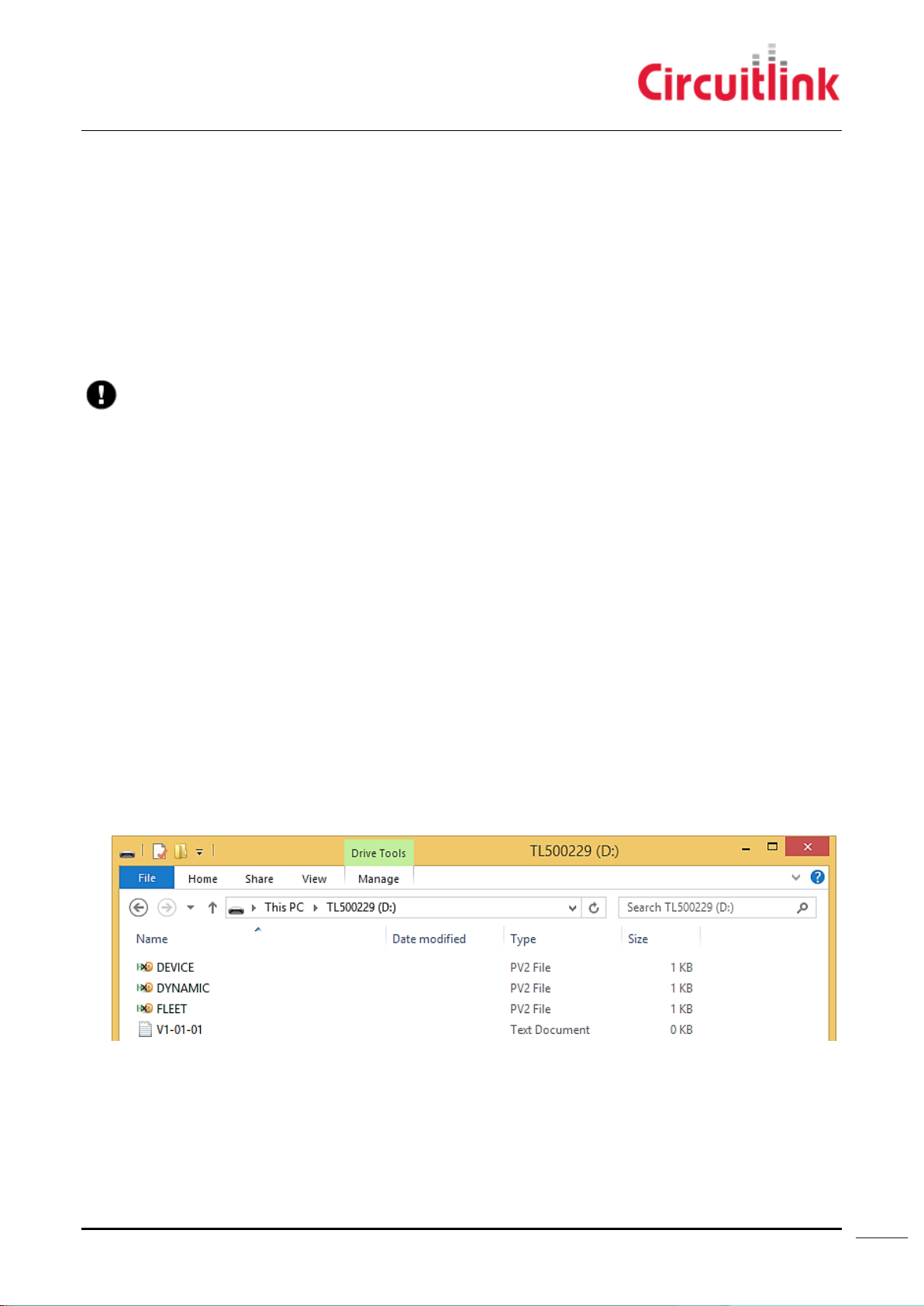
Do not delete or modify the Device configuration file. This file is required for the device to operate
Configuration files use the .PV2 file extension. Fleet and Dynamic configuration files hold different variables for each
device.
Fleet contain parameters required to set how the data recorder operates. This can be anything from accelerometer
configuration to CAN/OBD packet settings.
The process and handling of configuration files in the EDR and Remote Accelerometer is different due to the differences in
firmware and flash storage architecture.
As the Remote Accelerometer is a transducer that does not store any data, the available storage to hold configuration files
is only a few kilobytes. Because of this, it will not hold multiple copies of the same file like how the EDR operates.
Event Data Recorder
The process for updating configuration is the same for all event data recorders regardless of the firmware version or
family.
1. Connect the T5 to power and allow it to boot up.
2. Connect a USB cable from the T5 to your PC
3. Open My Computer and navigate to the removable storage device with the label that of the T5
4. Place the desired configuration file in the PARAMS.
5. Disconnect the USB to reinitialise the device
Remote Accelerometer
The Remote Accelerometer will only hold one fleet configuration file in its internal storage at any time.
1. Connect the RA to power and allow it to boot up.
2. Connect a USB cable from the RA to your PC
3. Open My Computer and navigate to the removable storage device with the label that of the RA
4. Place the desired configuration file in the root of the drive.
The device will reinitialise and process the file. A status file will be present in the drive indicating if the update was
successful.
5. Disconnect the USB to reinitialise the device
A completed unit ready for use.
Circuitlink Pty Ltd, ABN 80 057 670 505, 7/30 Foundry Road, Seven Hills NSW 2147 Australia T: +61 2 9624 1922 F: +61 2 9624 1911
E: [email protected] Document Status: Final. Publish Date: 9/02/2015
CIRCUITLINK.COM.AU
Page 18
18
Troubleshooting
Do not disconnect the USB cable while the application is running. This will cause unexpected results
when trying to reconnect the unit.
Circuitlink Configuration Utility
View Live Data
Circuitlink has developed an application to interactively monitor live inputs and activity on the Tacholink T5
1. With the T5 connected to the vehicle and turned on, unscrew the dust cover from the USB port and connect a
mini USB B to USB A from it to your computer.
2. The T5 will mount itself as a volume in My Computer and set up a virtual COM port.
3. Download and install CLConfig from :
http://t5production.circuitlink.com.au:2370/CLConfig/publish.htm
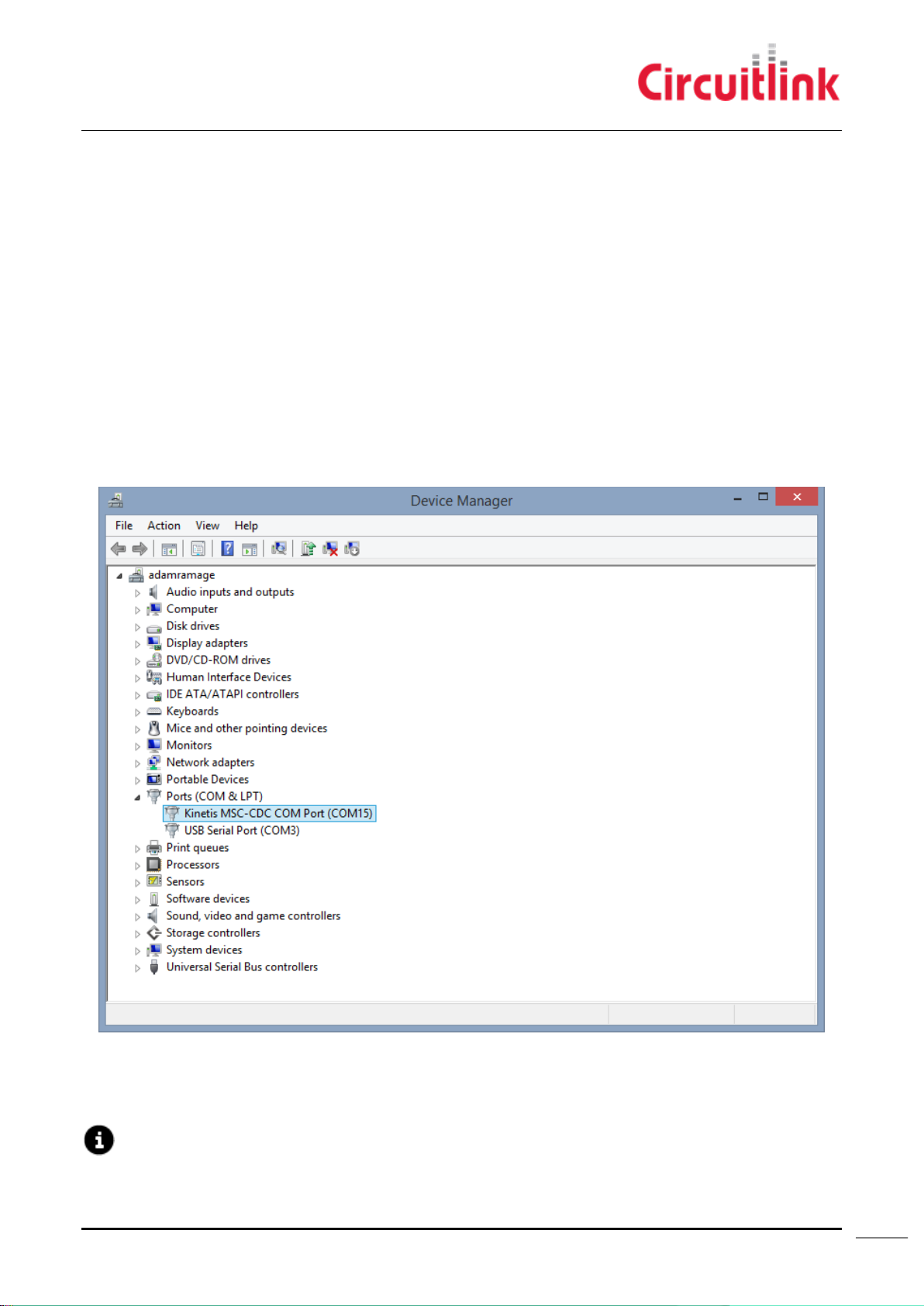
4. If you have multiple serial devices connected, open Device Manager to determine which port to use. (Start >
Run > devmgmt.msc).
i. Expand your computer name > Ports (COM & LPT).
ii. Identify the COM# affixing the Kinetis MSC-CDC COM Port device.
Figure 6 - Locating the T5 when there are multiple COM ports
5. Launch CLConfig.
Circuitlink Pty Ltd, ABN 80 057 670 505, 7/30 Foundry Road, Seven Hills NSW 2147 Australia T: +61 2 9624 1922 F: +61 2 9624 1911
E: [email protected] Document Status: Final. Publish Date: 9/02/2015
CIRCUITLINK.COM.AU
Page 19
19
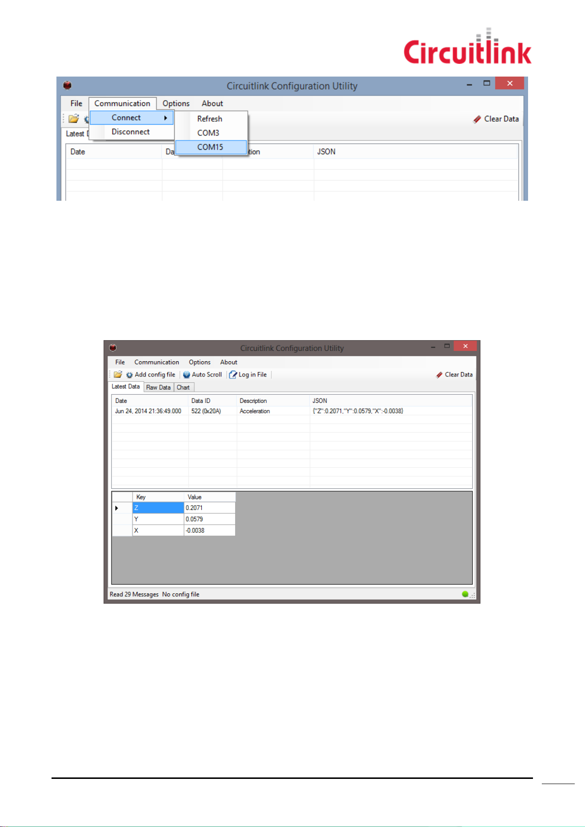
6. From the Communication menu, connect to the COM port for your unit as found in step 4.
7. If you have the configuration file available, you can populate the labels for each input by adding the
configuration file. For best results, this can be located by navigating to the PARAMS folder on the unit after
selecting the Add config file button in the menu. The T5 operating system is designed to select the latest
configuration file from this folder. The configuration file follows the following scheme : Fleet-YYYY-MM-DDHH-MM-SS.pv2
8. When you are finished with the utility disconnect the device by selecting Disconnect from the
Communication menu. If the device was removed without disconnecting it first, the serial port may remain
locked by the application. With the USB cable disconnected, close the Configuration Utility and restart the T5.
With power applied to the unit, reconnect the USB cable and launch the configuration utility.
Figure 7 - Circuitlink Configuration Utility during a live connection
Circuitlink Pty Ltd, ABN 80 057 670 505, 7/30 Foundry Road, Seven Hills NSW 2147 Australia T: +61 2 9624 1922 F: +61 2 9624 1911
E: [email protected] Document Status: Final. Publish Date: 9/02/2015
CIRCUITLINK.COM.AU
Page 20
20
View .TRD files
Viewing .TRD files allows you to analyse previous events and see some configuration parameters.
1. Open the Circuitlink Configuration Utility
2. From the File menu, Select Open and navigate to the .trd file you wish to view. If you’re retrieving this from
your device, it will be located in the DATA folder on the root of the drive.
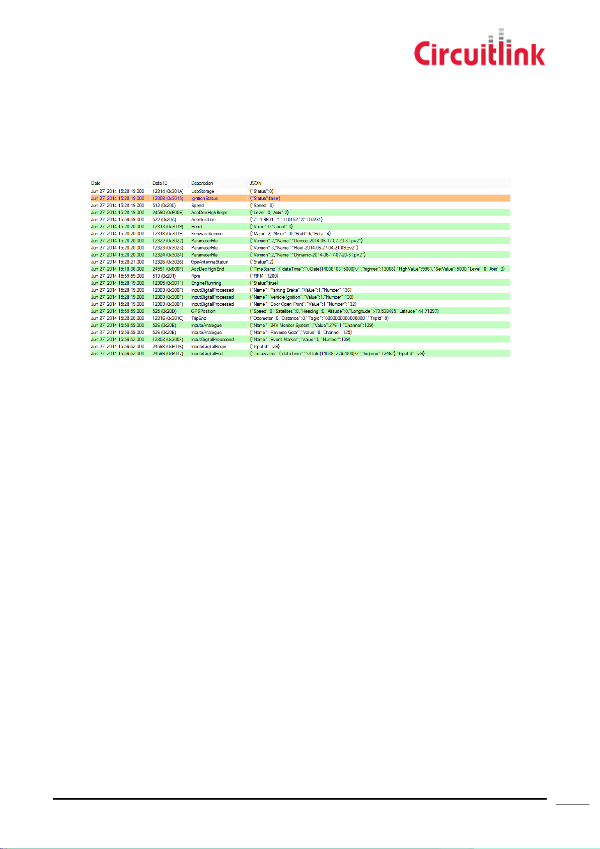
3. Raw Data will show data in chronological order as it was received by the unit whereas Latest data will show
the latest entry for each data input. Information can be sorted by selecting the corresponding header and
sorting ascending or descending.
An example of data received in a .trd file
Circuitlink Pty Ltd, ABN 80 057 670 505, 7/30 Foundry Road, Seven Hills NSW 2147 Australia T: +61 2 9624 1922 F: +61 2 9624 1911
E: [email protected] Document Status: Final. Publish Date: 9/02/2015
CIRCUITLINK.COM.AU
Page 21
21
LED Activity
Different firmware may display different results as of the publication of this document
Description
LED Pattern
Failed to get valid NMEA message from GPS module
Solid Red
Received valid NMEA message from GPS module but hasn't received
a valid position yet.
Solid Orange
Antenna open circuit, not connected
Flash Red Slow
Antenna short circuit.
Flash Red Fast
Received GPS valid position
Flash Green
Solid Amber
OFF
Flashing Green
Initialising after start-up
No activity
Receiving CAN data
Amber
Flashing Green
Flashing Red
- Failed to connect to server
- Connected to server
successfully but failed to
transfer all files to FTP server
- Open Live socket
successfully
- Transferred all file
successfully through FTP
- Login FTP successfully
and transferring files.
WIFI:
- Failed to connect to router
- Router failed to connect to internet
GSM:
- Failed to connect to GSM Modem
- SIM card error
- Failed to connect to GPRS network
- The GPRS network failed to connect to
internet
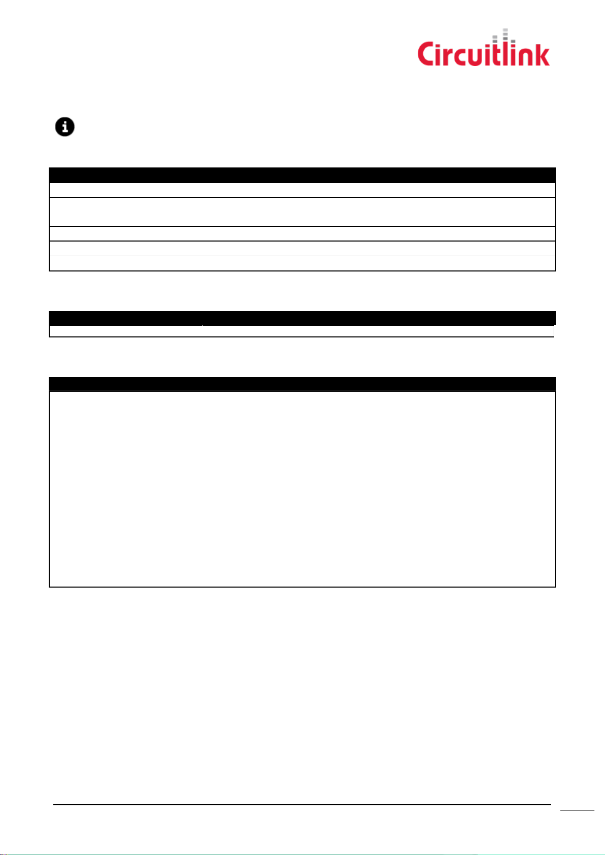
The LED’s on the face of the unit server to give a visual indicator of the activity currently occurring.
GPS
DATA
COMS
Often the LED’s will show a grouped message meaning there may be an issue with the system. For more information
regarding this, contact Circuitlink Support.
Circuitlink Pty Ltd, ABN 80 057 670 505, 7/30 Foundry Road, Seven Hills NSW 2147 Australia T: +61 2 9624 1922 F: +61 2 9624 1911
E: [email protected] Document Status: Final. Publish Date: 9/02/2015
CIRCUITLINK.COM.AU
Page 22
22
FCC Approved Antennas
The following antennas are FCC approved for use with the Tacholink 5 in the United States. Installation and use of
alternate antennas without written permission from Circuitlink Pty Ltd will void equipment warranty and may void
FCC approval to operate.
ANTENNA
WIFI
GPS
CELLULAR
TACHOLINK 5
MODEL
MA600 Combination
Yes
Yes
Yes
TACHO5A, 5B,
5C
MA.206 Combination
Yes
Yes
No
TACHO5B
Linx ANT-2.4-CW-RH
Yes
No
No
TACHO5B
Only one of the above antennas may be connected to the Tacholink 5 at one time.
The best choice of antenna for the TACHO5B will be determined by installation requirements.
Frequency (GHz)
824 ~ 896
1710 ~ 1880
1850 ~ 1990
Peak Gain (dBi)
2.1
2.9
3.0
Average Gain (dBi)
-4.7
-2.7
-3.1
Frequency (GHz)
2.4 – 2.6
Peak Gain (dBi)
2.1
Average Gain (dBi)
-2.3
Frequency (GHz)
2.4 – 2.5
Peak Gain (dBi)
3.4
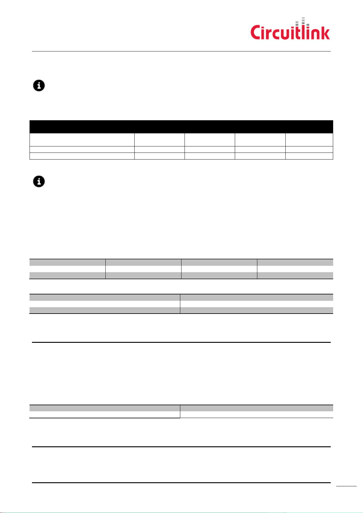
The MA600 and MA206 are combination antennas, the Linx antenna is Wi-Fi only. The following table summarizes the
capabilities of each antenna and the matching Tacholink 5 models.
MA600
This is a combined GPS/Cellular/2.4GHz 802.11 antenna manufactured by Taoglas, part number MA600.A.ABC.006.
Antenna Type
The cellular WWAN and 2.4GHz 802.11 Wi-Fi antennas within the MA600.A.ABC.006 are a type known as ‘planar
inverted F antennas’ (PIFA).
Cellular Antenna Gain
802.11 WiFi Antenna Gain
Antenna Cable Length
The MA600.A.ABC.006 is supplied with 3m +/-30mm cables for the Cellular, 802.11 and GPS antennas.
MA206
This is a combined GPS/2.4GHz 802.11 antenna manufactured by Taoglas, part number MA206.A.AB.004.
Antenna Type
The 2.4GHz 802.11 WiFi antenna within the MA206.A.AB.004 is a dipole.
802.11 WiFi Antenna Gain
Antenna Cable Length
The MA206.A.AB.004 is supplied with 3m +/-30mm cables for the 802.11 and GPS antennas.
Circuitlink Pty Ltd, ABN 80 057 670 505, 7/30 Foundry Road, Seven Hills NSW 2147 Australia T: +61 2 9624 1922 F: +61 2 9624 1911
E: [email protected] Document Status: Final. Publish Date: 9/02/2015
CIRCUITLINK.COM.AU
Page 23

23
ANT-2.4-CW-RH
Frequency (GHz)
2.39 – 2.49
Peak Gain (dBi)
-0.9
This is a 2.4GHz 802.11 antenna manufactured by Linx, part number ANT-2.4-CW-RH-SMA.
Antenna Type
The antenna is a ¼ wave helical whip.
Antenna Gain
Antenna Cable Length
This antenna has no cable. It is fitted with an SMA connector for direct connection to the Tacholink 5.
Circuitlink Pty Ltd, ABN 80 057 670 505, 7/30 Foundry Road, Seven Hills NSW 2147 Australia T: +61 2 9624 1922 F: +61 2 9624 1911
E: [email protected] Document Status: Final. Publish Date: 9/02/2015
CIRCUITLINK.COM.AU
Page 24

24
Contact Information
For questions and or amendments to this guide, please contact:
Circuitlink Pty Ltd
7/30 Foundry Road, Seven Hills NSW 2147 Australia
T: +61 2 9624 1922
F: +61 2 9624 1911
E: [email protected]
W: CIRCUITLINK.COM.AU
General Support Enquiries:
Circuitlink Pty Ltd, ABN 80 057 670 505, 7/30 Foundry Road, Seven Hills NSW 2147 Australia T: +61 2 9624 1922 F: +61 2 9624 1911
E: [email protected] Document Status: Final. Publish Date: 9/02/2015
CIRCUITLINK.COM.AU
Page 25
25
Revision History
Version
Date
Change
Author
1.0
14/7/14
Initial Version
A.Ramage
1.1
14/7/14
Pre-release amendments
A.Ramage
1.2
29/9/14
Adjusted formatting and cable diagrams
A.Ramage
1.3
8/12/14
FCC Warnings updated
Antenna Specifications added
J. Skeen
1.4
18/12/14
FCC Logo removed from P5
J. Skeen
1.5
20/01/15
FCC warning statement changed FCC
Label statement deleted modifications put
into separate section
J. Skeen
1.6
30/01/15
Added instruction for loading new
configuration file
Added notes for Remote Accelerometer
Added minimum specification for Intelligo
and CLConfig
Final release
A.Ramage
1.7
9/2/15
Added Voltage and Current specifications
Updated wording for RF Radiation
Exposure Statement
Updated document format to include
document status and publish date in footer
Added vehicle fusing recommendation
Added information on antennas versus
Tacholink models
Added information on fitting one antenna at
a time
A.Ramage/JSkeen
Table 1 - Revision History
Circuitlink Pty Ltd, ABN 80 057 670 505, 7/30 Foundry Road, Seven Hills NSW 2147 Australia T: +61 2 9624 1922 F: +61 2 9624 1911
E: [email protected] Document Status: Final. Publish Date: 9/02/2015
CIRCUITLINK.COM.AU
 Loading...