

Page 1
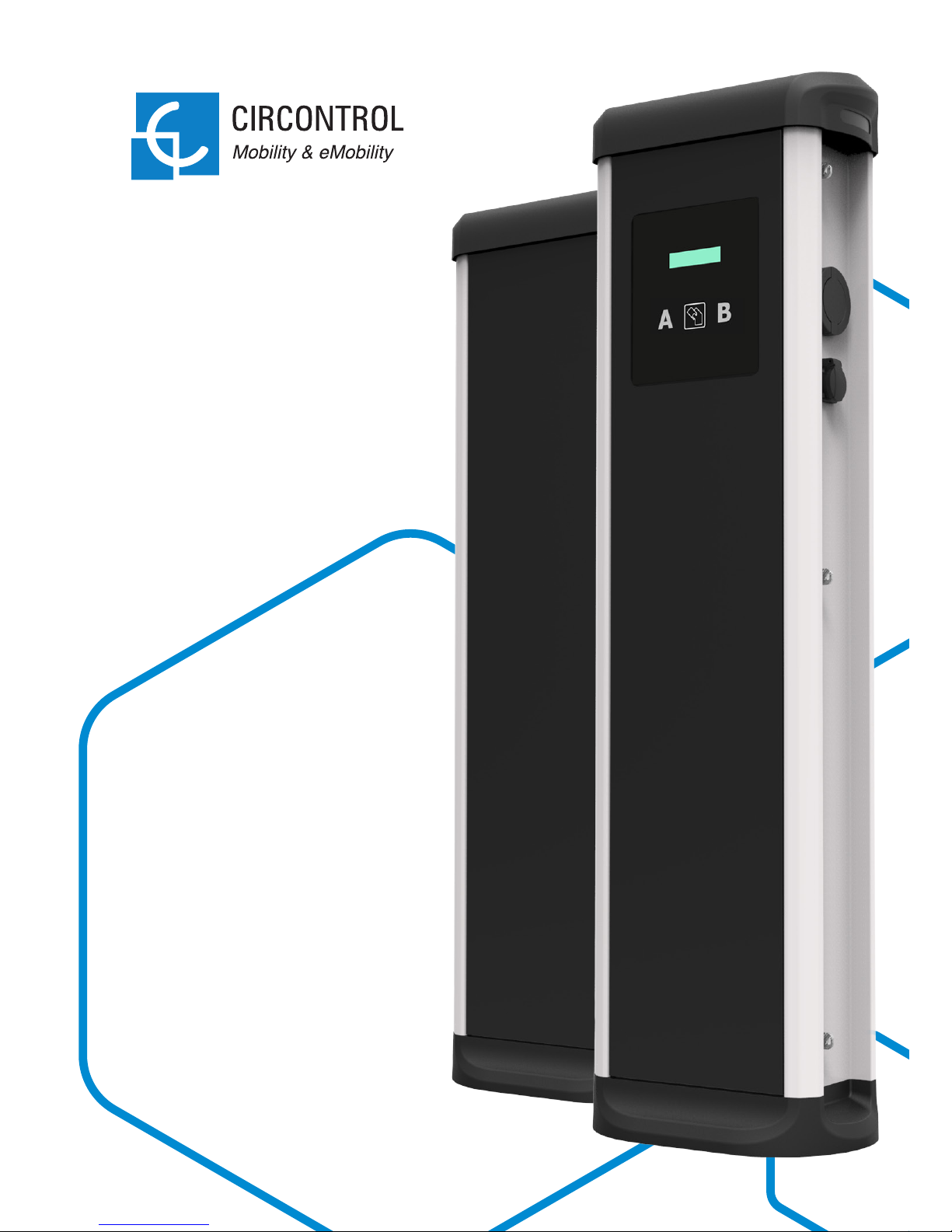
Installation Manual
Post
eVolve
Series
Page 2

Post eVolve Series
Installation Manual
COPYRIGHT INFORMATION
This document is copyrighted, 2017 by Circontrol, S.A. All rights are reserved.
Circontrol, S.A. reserves the right to make improvements to the products
described in this manual at any time without notice.
No part of this manual can be reproduced, copied, translated or transmitted in
any form or by any means without the prior written permission of the original
manufacturer. Information provided in this manual is intended to be accurate and
reliable. However, the original manufacturer assumes no responsibility for its
use, or for any infringements upon the rights of third parties athat may result
from its use.
All other product names or trademarks are properties of their respective owners.
Page 3

1 — So, hello!
2 — Before the
installation
3 — Dimensions
and Overview
4 — Installation
5 — Technical
Data
6 — Need Help?
Here’s your guide
to install eVolve.
03
04
10
12
18
21
Page 4

02
Post eVolve Series Installation Manual
1
Page 5
03
This manual provides commissioning information, which has been designed
and tested to allow electric vehicle charging, specified in IEC 61851.
This document has different sections such as step-by-step installation
procedure and technical data.
ELECTRIC RISK
Take precautions to make the electrical connection inside the
unit.
Unit must be disconnected from any power source during
commissioning.
ATTENTION!
Indicates that the damage to property can occur if appropiate
precautions are not taken
So, hello!
THE FOLLOWING SYMBOLS ARE USED FOR IMPORTANT
SAFETY INFORMATION IN THIS DOCUMENT
• Complies with IEC 61851, Electric vehicle conductive
charging system (IES 61851-1 and IEC 61851-22).
• Complies with IEC 62196, Plugs, socket-outlets, vehicle
couplers and vehicle inlets (IEC 62196-1 and IEC 62196-2).
• Standards: 2014/35/UE, LVD;2014/30/UE, EMC.
• RFID complies with ISO 14443A/B
Page 6
04
Post eVolve Series Installation Manual
The charge point is designed for installation in indoor and outdoor areas. For each of
the different conditions of installation, the unit must be installed safely and ensure
adequate protection.
• Charge point must not be installed
in areas where there is potential
risk of explosions.
• Do not install the charge point
where falling objects may damage
the equipment.
• The surface where the charge
point is placed must withstand the
mechanical forces.
• Do not use this unit for anything
other than electric vehicle
charging modes are expected in
IEC 61851.
• Do not modify this unit. If modified,
CIRCONTROL will reject all
responsibility and the warranty
will be void.
• Comply strictly with electrical
safety regulations according to
your country.
• Do not make repairs or
manipulations with the unit
energised.
• Only trained and qualified
personnel should have access to
low-voltage electrical parts inside
the unit.
• Check the installation annually by
qualified technician.
• Remove from service any item that
has a fault that could be dangerous
for users (broken plugs, caps that
don’t close...).
• Use only Circontrol supplied spare
parts.
• Do not use this product if the
enclosure or the EV connector is
broken, cracked, open, or shows
any other indication of damage.
Refer to TECHNICAL DATA section for more information about environmental
installation conditions.
IMPORTANT SAFETY INSTRUCTIONS
Read carefully all the instructions before starting in order to ensure properly installation of the charge point.
2
Page 7
05
ELECTRICAL WIRING CONSIDERATIONS
1 — CHARGE POINT – INPUT POWER SUPPLY
Charge point may not include elements of electrical protection.
The input power supply line must be hardwired from a distribution board to the charge
point under electrical safety regulations according to your country regulations.
2 — POWER SUPPLY LINE DIMENSIONING
The dimensioning of the input power supply line of the charge point must be checked
by a qualified electrician. Note that various factors such as cable length between
distribution board and charge point, maximum output current of the charge point
may have influence of the selected cable.
In such cases, increasing the cable cross-section it is required to adapt the
temperature resistance of the power supply line.
3 — CHARGE POINT – MAXIMUM CURRENT OUTPUT
Please refer to the TECHNICAL DATA section to consult the default factory settings
from maximum output current of the charge point.
If the power supply is less than maximum output current and adjustment to a lower
nominal current needs to be performed, please refer to the INSTRUCTION MANUAL.
Depending of the model this value may vary.
Take into consideration this section before start wiring
connections of the charge point.
Before the
installation
Page 8
06
Post eVolve Series Installation Manual
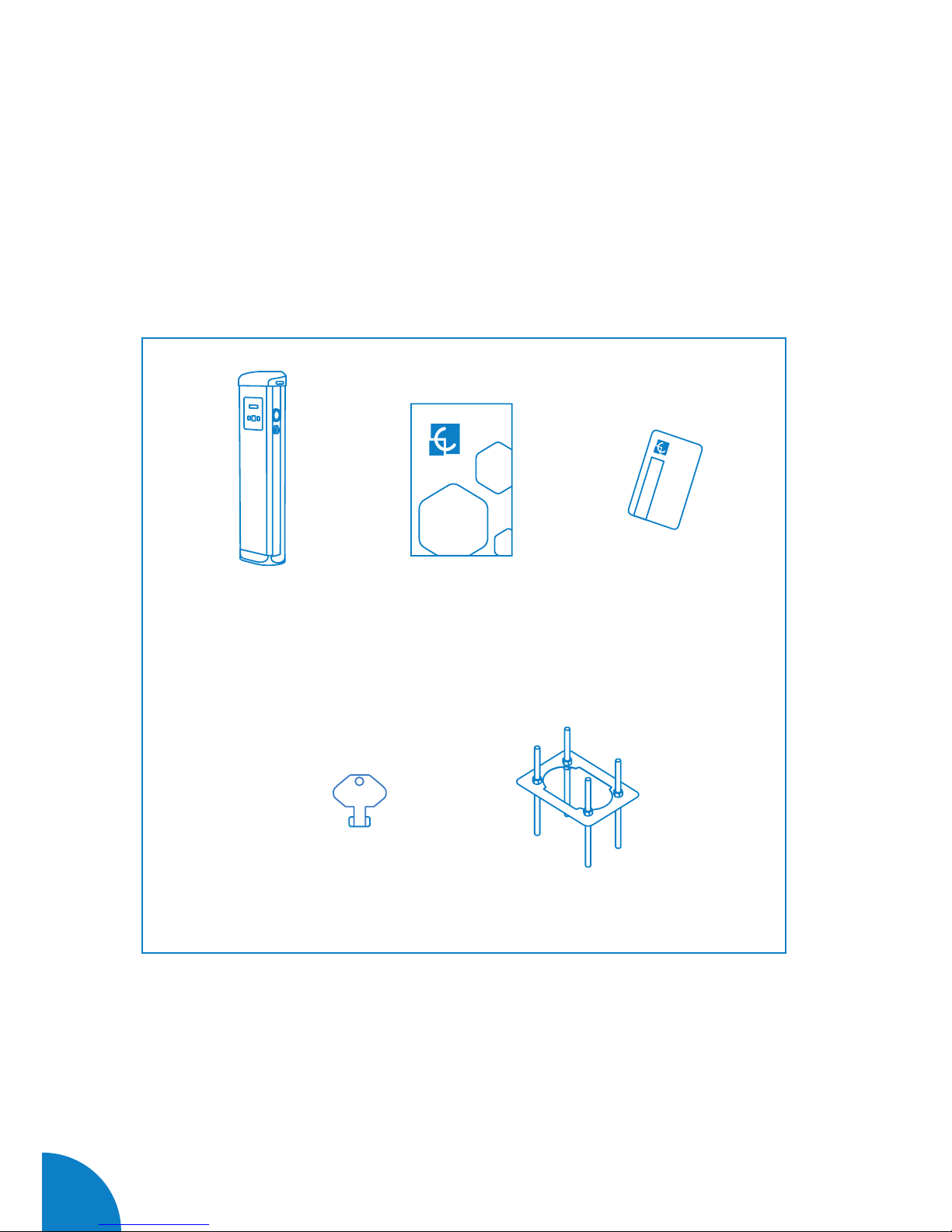
What’s included:
Charge Point Installation
Manual
CirCarLife RFID
Mifare Card
eVolve Post Key Foundation Kit
Page 9
07
50
500
500
x
*
Measures in mm
A
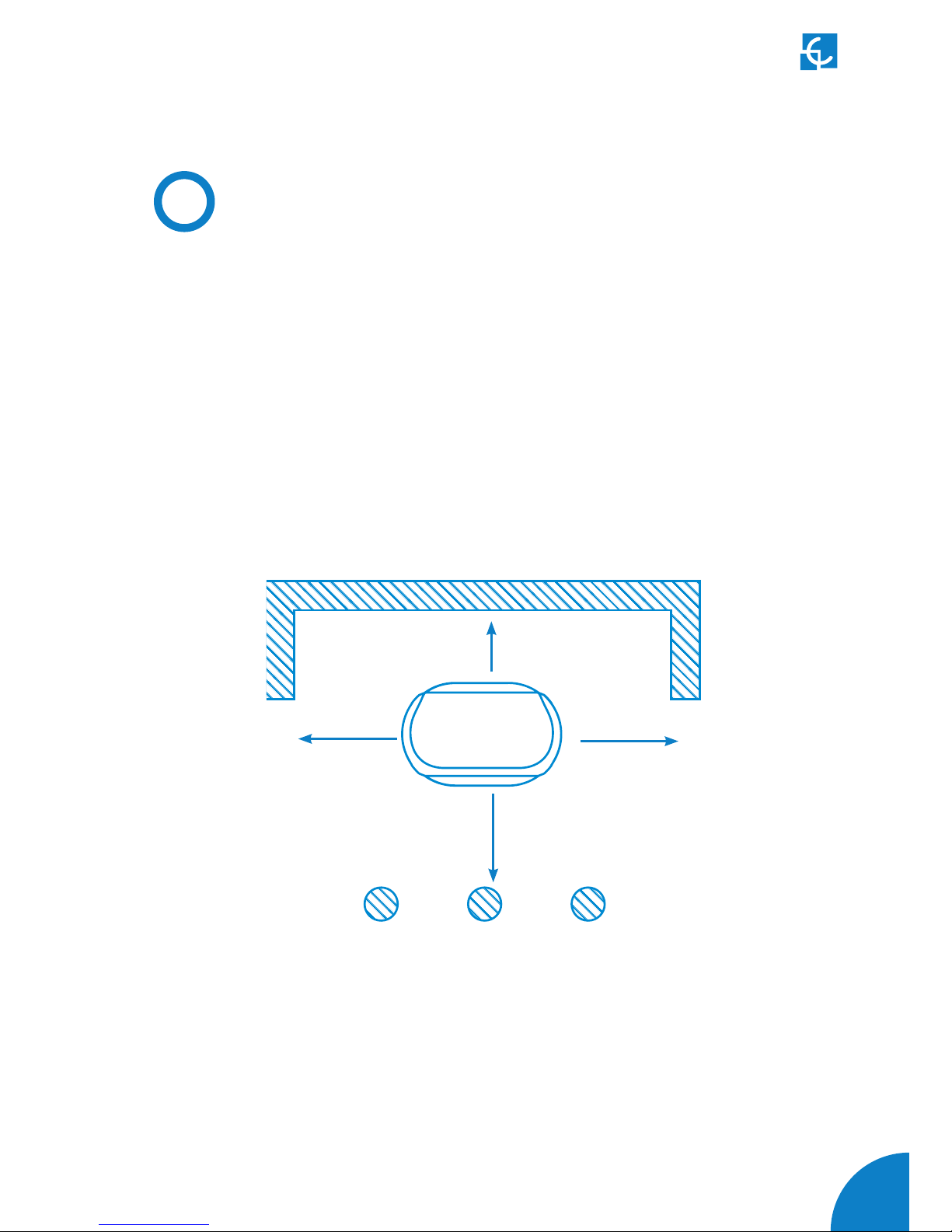
Minimum Distances
When installing the unit, respect the minimum distances space for maintenance and
safety reasons.
Please comply accordingly to your country specifications.
The next picture shows how it should be installed.
• Do not install near areas where water or fluids can penetrate into the unit.
• Do not install the unit in unstable terrain.
(*) If Bollard Impact Protector is installed, keep 500 mm as a minimum distance in
order to give enough space to open the frontal door of the charge point for maintance
tasks.
Page 10

08
Post eVolve Series Installation Manual
Foundation Kit:
Nuts M16
Template Foundation bolt
8x
1x 4x
Page 11
09
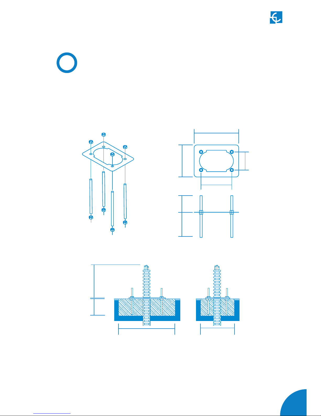
B
Foundation
450
180
119
230
320
200
Measures in mm
• Place the foundation bolts into the template using provided nuts with the help
of a 24mm open-end wrench.
• Once the kit is assembled, it must be placed in the ground taking into
consideration the following measures.
Note: In the event of any doubt about the terrain regarding the installation of this
unit, due to the weight and dimensions, it will be necessary to define a final solution
to install the unit. It must be confirmed by a specific technical project made for an
architectural firm prior to its installation.
220
130
500
300
Front view
Side view
Page 12
10
Post eVolve Series Installation Manual
3
446234
1544
1351
113
80
180
Measures in mm
438
288
Page 13
11
Dimensions
and Overview
1
2
3
4
5
6
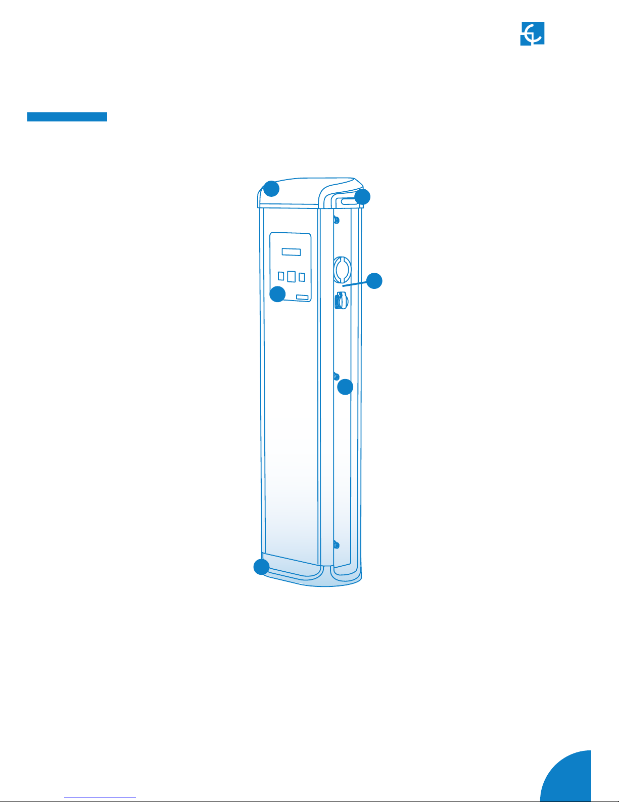
1 — Hat
2 — LED Beacons
3 — Display & RFID Reader*
4 — Plugs**
5 — Key lock access
6 — Base
(*) Only Smart Series
(**) Plugs may vary depending on the model
Page 14
12
Post eVolve Series Installation Manual
4
A
1 2
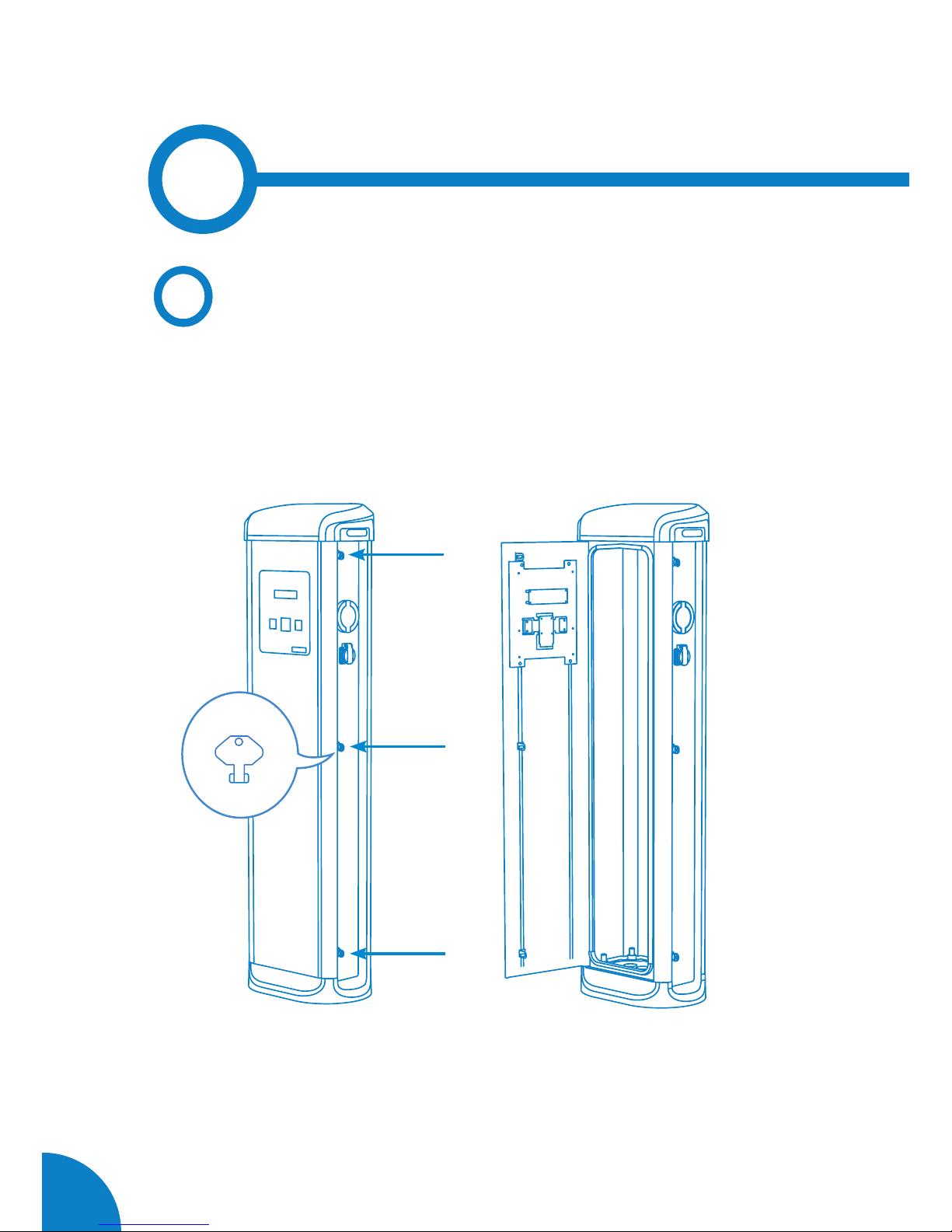
Opening
Use provided key in order to open the unit:
Page 15
13
Installation
B
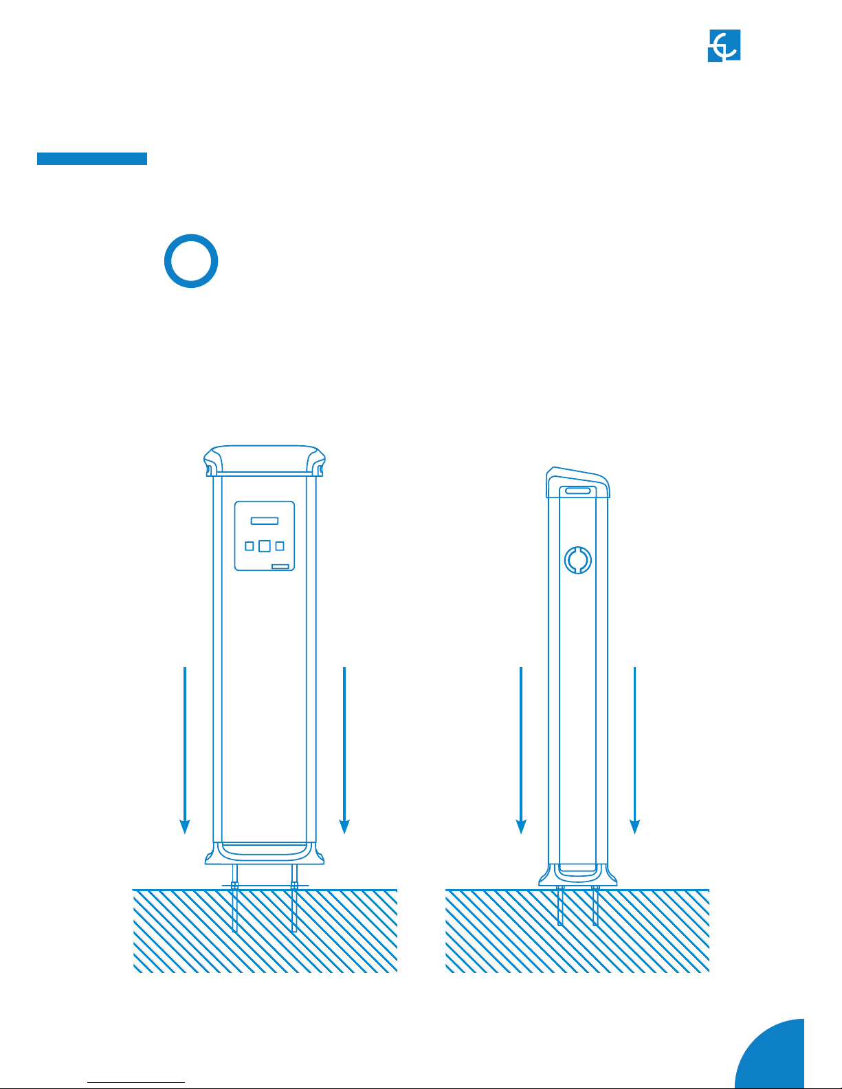
Positioning
1. Remove the template nuts before proceeding.
2. Place the charge point through the four foundation bolts.
Page 16
14
Post eVolve Series Installation Manual
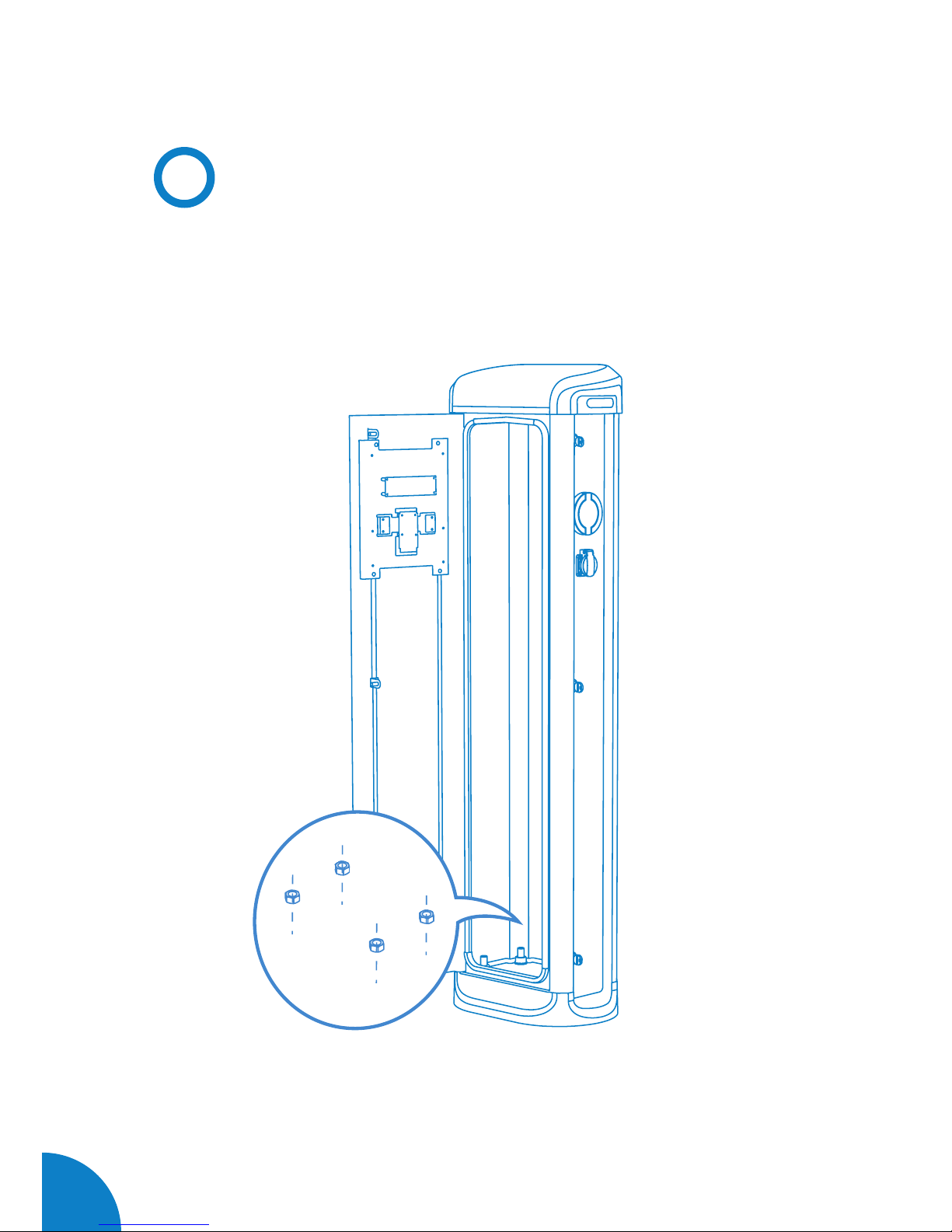
Firmly tighten the 4 nuts using a 24mm open-end wrench.
C
Fixation
Page 17
15
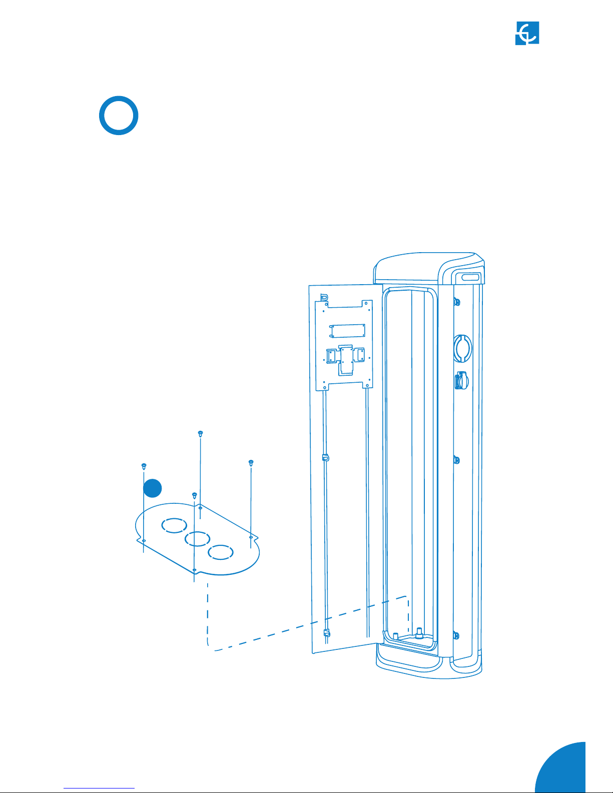
• It is recommended to install a cable glands
(not supplied) in pre-holes position.
• Assembly metal plate using the 4 supplied
screws as shown below:
4x
D
Metal plate
Page 18
16
Post eVolve Series Installation Manual
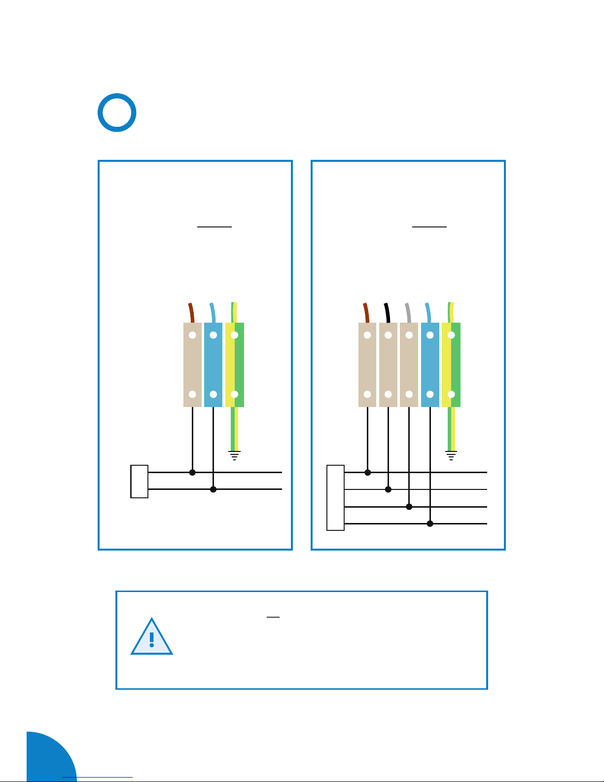
• Make sure all screws are securely tightened
• Do not forget to connect the ground cable to the
ground terminal
• Terminal block maximum cross-section: 35mm
2
L
L1
N
L2
L3
N
E
Wiring
SINGLE-PHASE CHARGE POINT
• Connect to the 230VAC.
THREE-PHASE CHARGE POINT
• Connect to the 400VAC.
• If the Power Supply is SinglePhase, connect L1 and N.
Page 19
17
Verification
1 — POWER INPUT
Before proceeding, make sure voltage is present in the terminal blocks.
For Three-Phase models pay special attention to Neutral Cable.
2 — MAINTENANCE MODE
Pull outward the Tamper Switch located in the lower half of the Charge Point.
3 — CAREFUL WITH THE WIRES
When closing the unit, keep in mind all cables should remain inside.
4 — CHECK THE PLUGS
Plugs should be in good conditions before starting the unit.
5 — OPERATION
Check no abnormal noise appears while the unit is charging.
6 — CHECK THE BEACON INDICATORS
All beacon indicators should light properly. Here’s the reference:
PLUG STATE
Available
Charging
Fault
BEACON COLOR
Green
Blue
Red
F
Page 20

18
Post eVolve Series Installation Manual
5
MECHANICAL DATA
Enclosure rating
IP54 / IK10
Enclosure material
Aluminium & ABS
Enclosure door
Frontal key locked door
Net weight
55Kg
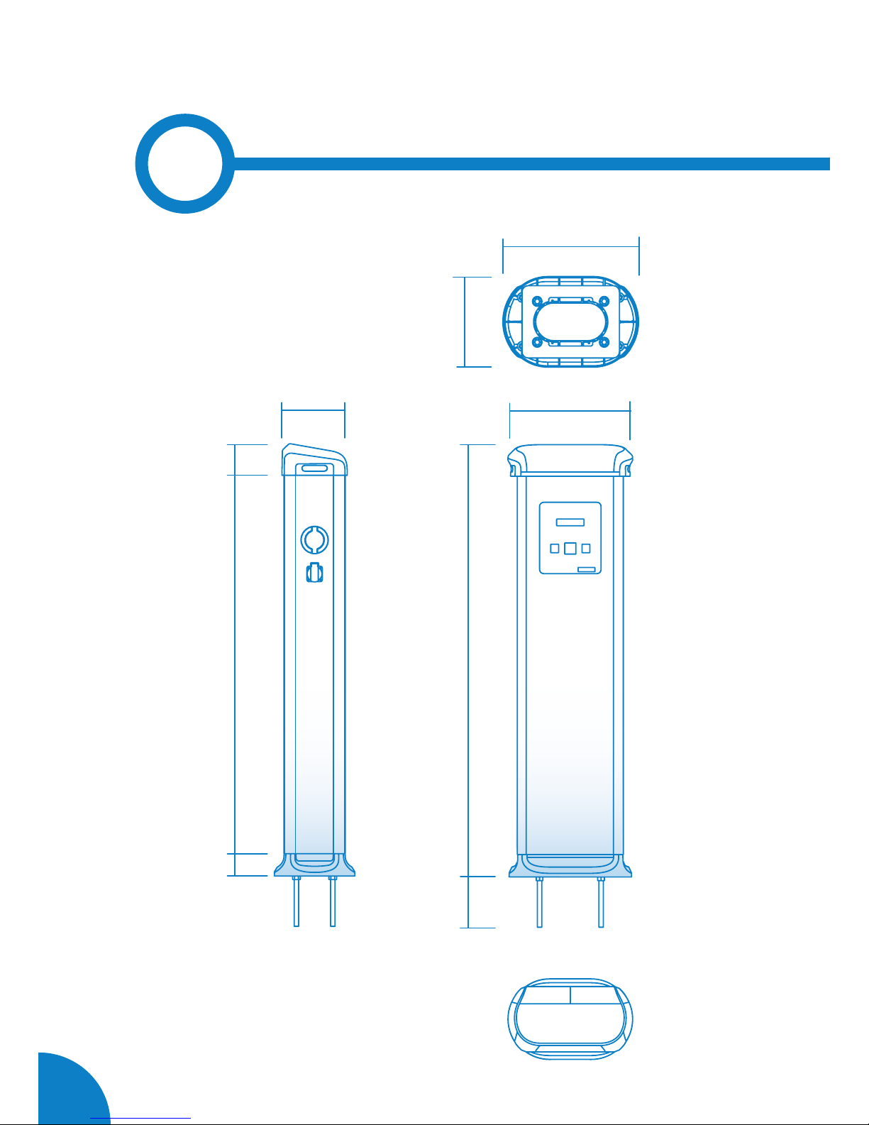
Dimensions (W x H x D)
450 x 1550 x 290 mm
ENVIRONMENTAL CONDITIONS
Operating temperature
-5ºC to +45ºC
Operating temperature with
Low Temperature Kit*
-30ºC to +45ºC
Storage temperature
-20ºC to +60ºC
Operating humidity
5% to 95% Non-condensing
GENERAL DATA
Display*
LCD Multi-language
Light beacon
RGB Colour indicator
RFID reader*
ISO / IEC 14443A/B
MIFARE Classic/Desfire EV1
ISO 18092 / ECMA-340
NFC 13.56MHz
CONNECTIVITY
Ethernet*
10/100BaseTX (TCP-IP)
Cellular*
Modem 3G / GPRS / GSM
Interface protocol*
OCPP
Page 21

19
Technical Data
ELECTRICAL DATA
Power supply
1P+N+PE / 3P+N+PE
Input voltage
230VAC+/- 10% / 400VAC+/-10%
Frequency
50Hz / 60Hz
Overcurrent protection
MCB (curve C)
Safety protection
RCD Type A (30mA) / Type B*
Surge protection*
Transient surge protector
IEC 61643-1 (Class II)
MODEL** CONNECTORS
OUTPUT
CURRENT
OUTPUT
POWER
MINIMUM
CABLE CROSS-
-SECTION***
S
Type 2 Socket
Type 2 Socket
32A
32A
7,4kW
7,4kW
25mm
2
T
Type 2 Socket
Type 2 Socket
32A
32A
22kW
22kW
25mm
2
S-one
Type 2 Socket 32A 7,4kW 10mm
2
T-one
Type 2 Socket 32A 22kW 10mm
2
SM
Type 2 Socket
CEE 7/3
32A
16A
7,4kW
3,6kW
16mm
2
TM
Type 2 Socket
CEE 7/3
32A
16A
22kW
3,6kW
16mm
2
SM4
Type 2 Socket / CEE 7/3
Type 2 Socket / CEE 7/3
32A / 16A
32A / 16A
7,4kW / 3,6kW
7,4kW / 3,6kW
25mm
2
TM4
Type 2 Socket / CEE 7/3
Type 2 Socket / CEE 7/3
32A / 16A
32A / 16A
22kW / 3,6kW
22kW / 3,6kW
25mm
2
(*) Depending on the model, some components may vary
(**) For availability of models, please consult your local supplier
(***) This is the minimun cable section recommended for the maximum AC input current,
the final section must be calculated by a qualified technician taking into account the specific
conditions of installation
Page 22

20
Post eVolve Series Installation Manual
6
Page 23

21
Need help?
In case of any query or need further information, please
contact our Post-Sales Department
(+34) 937 362 940 (+34) 937 362 941
[email protected] circontrol.com
Page 24

CIRCONTROL eVOLVE
INSTALLATION MANUAL
A comprehensive guide on how
to install and verify your eVolve.
V2.1, August edition 2017
Rev.40
CIRCONTROL S.A. - ALL RIGHTS RESERVED
 Loading...