

Instruction Manual
Raption 50
Series


Raption 50 Series
Instruction Manual
COPYRIGHT INFORMATION
This document is copyrighted, 2017 by Circontrol, S.A. All rights are reserved.
Circontrol, S.A. reserves the right to make improvements to the products
described in this manual at any time without notice.
No part of this manual can be reproduced, copied, translated or transmitted in
any form or by any means without the prior written permission of the original
manufacturer. Information provided in this manual is intended to be accurate
and reliable. However, the original manufacturer assumes no responsibility for
its use, or for any infringements upon the rights of third parties that may result
from its use.


01
Here’s your guide to
use and configure
Raption 50
1 — So, Hello! 02 5 — OCPP integrations 62
2 — Features 04 6 — 3G Communications 74
3 — How to use it? 12 7 — Technical Data 80
4 — How to configure it? 40 8 — Need Help? 84

02
Raption 50 Series Instruction Manual
This manual contains all the necessary information for the proper use of the
Charge Point and helps the user to perform charging with a high level of efficiency
and safety.
The CIRCONTROL Charge Point provides the fastest way to charge electric vehicles
nowadays. Its innovative and original design provides a quick and intuitive way
for recharging their vehicle, according to the current regulations. You can make
loads into alternating current (AC) and direct current (DC), either individually or
simultaneously.
The unit integrates an intuitive user interface and easy to use, it is an 8” touch
screen by which all necessary for recharging operations are performed. It has
been designed vandal-proof in compliance with all requirements regarding IK
indices. In addition, the Charge Point also has a communications system that
allows monitoring and control remotely via OCPP and use XML parameters and
information while the recharging is being performed. This feature provides an
easy way to integrate the device into superior systems that allow to the owner or
system manager monitor the Charge Point status and recharge.
1
• Compliant with IEC 61851; Electric vehicle conductive charging
system (IEC 61851-1, IEC 61851-22 and IEC 61851-23).
• Compliant with IEC 62196; Plugs, sockets-outlets, vehicle
connectors and vehicles inlets, Conductive charging of electric
vehicles (IEC 62196-1, IEC 62196-2 and IEC 62196-3).
• Compliant with CHAdeMO certification.
• Meets the CCS specification, ISO/IEC 15118 and DIN SPEC 70121.
• Directives: 2014/53/UE, Radio and Telecommunication Terminal
equipment; 2014/30/UE, Electromagnetic Compatibility (EMC);
2014/35/UE, Low Voltage directive.
• RFID complies with ISO 14443A/B
03
So, hello!
Important safety instructions
• Read all the instructions before
using and configuring the Charge
Point.
• Do not use the Charge Point
for anything other than electric
vehicle charging modes are
expected in IEC 61851.
• Do not modify the Charge Point. If
modified, CIRCONTROL will reject
all responsibility and the warranty
will be void.
• Comply strictly with electrical
safety regulations according to
your country.
• Do not make repairs or
manipulations with the unit
energized.
• Only trained and qualified
personnel should have access
to the electrical parts inside the
Charge Point.
• Check the installation annually by
qualified technician.
• Remove from service any item
that has a fault that could be
dangerous for users (broken
connectors, caps that don’t
close...).
• Use only Circontrol supplied
spare parts.
• Do not use this product if the
enclosure or the EV connector is
broken, cracked, open, or shows
any other indication of damage.
Read carefully all the instructions before using the
charge point.

04
Raption 50 Series Instruction Manual
2
A
Main features
• HMI: there is a TFT colour touch screen of 8 inches, is the interface between the
Charge Point and the user. Provides detailed information for starting and stopping
the charge, including information concerning the recharge that is in progress
(charge state of the battery, charging time remaining, etc.).
• RFID: there is a radio frequency reader that allows user authentication to proceed
with the recharging of the electric vehicle. At the discretion of the facility operator,
the user’s recharge also can be allowed or denied.
• User Management: provides a database that associates users with one or more
identification cards, you can also assign consumption and charging logs.
• Beacons light: by a LED beacons located above connectors, it is indicated the
charging status of the socket/connector.
• Ethernet: the unit allows communicate using TCP / IP on an Ethernet network,
giving flexibility to the system operator and management of the Charge Point.
• Remote monitoring and control in real-time 3G: It can be done a remote device
connection or make OCPP integrations thanks to 3G modem is integrated. In
addition, by using a standard Web browser you can access your computer to
monitor the status of recharge and even run a Start / Stop remote.
• Historic charge transactions: the system is able to generate charging process
reports, according to the historical database of the Charge Point.
• Energy metering: Integrated meter, independent for AC and DC, is measuring
power and energy consumed by the EV during a charge transaction.
• OCPP integration: OCPP is a communication protocol between the Charge
Point and management platforms (BackOffice) for comprehensive management
of charging. This integration allows, among other things, management and user
authentication as well as a variety of parameters to monitor during a recharge.
05
Features
B
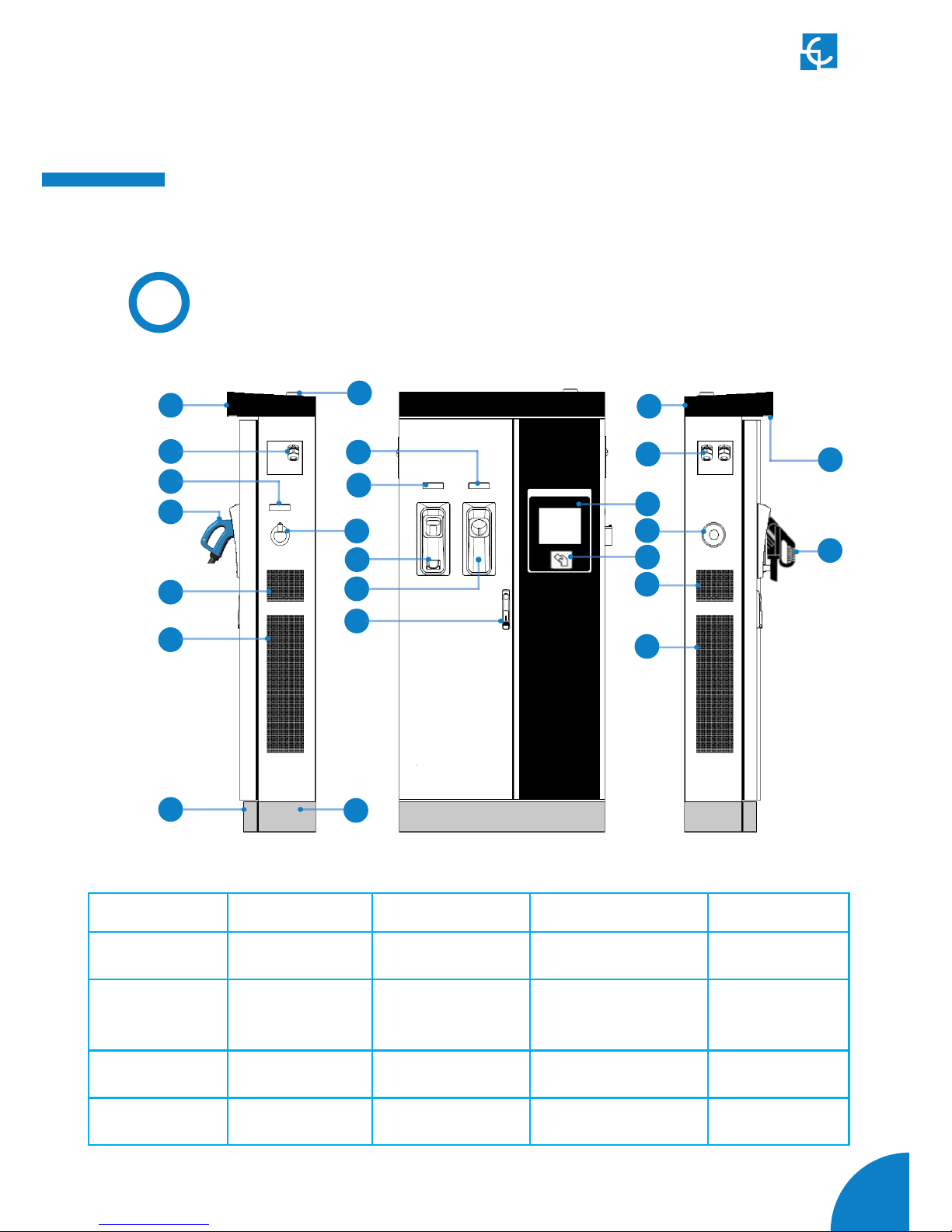
Overview
1- Cover 2- exit AC cable 3- AC light beacon 4- CHAdeMO connector 5- Unit air inlet
6- Power M. air outlet 7- D. front panel 8- D. rear panel 9- Handle 10- CHAdeMO holder
11- CCS holder 12- AC holder or
socket 32A *
13- CCS light beacon 14- CHAdeMO light beacon 15- 3G Antenna
16- Unit air outlet 17- exit DC cable 18- Touch screen 19- Emergency button 20- RFID reader
21- Unit air inlet 22- Power M. air inlet 23- CCS connector 24- Courtesy light
1
3
2
5
6
7
16
8
4
9
10
11
12
13
14
15
18
19
20
17
21
22
23
24
(*) Depending of the model, the components can vary.

06
Raption 50 Series Instruction Manual
C
Dimensions
• Units specified in millimeters:
07
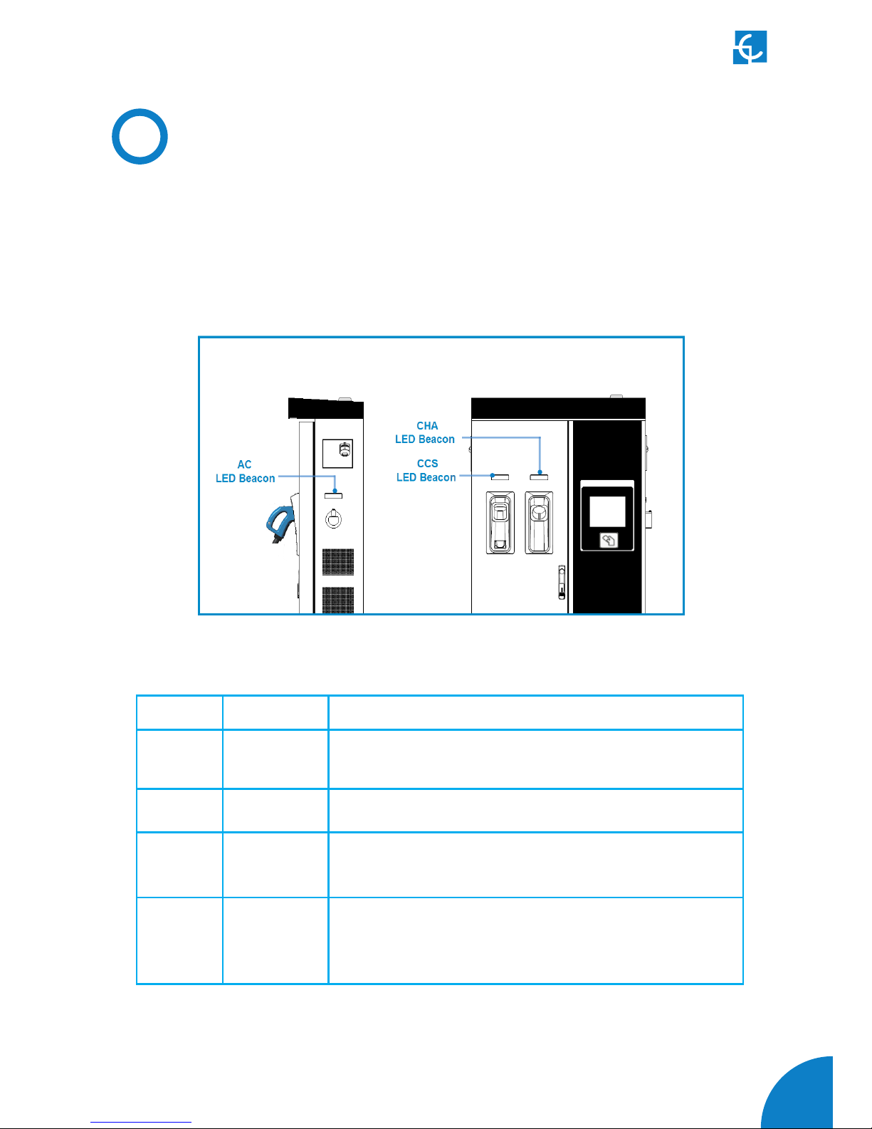
D
Status LED
Over each connector there is a beacon light, it indicates the state of charge in which
the socket/connector is located.
Colour Status Description
Green Available The connector or socket is available to start a charging
session
Blue Charging The connector or socket is performing a charging session
Cyan Booked
(OCPP 1.5)
The connector or socket has been booked by system
operator through OCPP
Red Error
The Charging Station indicates that the emergency
button has been activated or some error has occurred.
Check the HMI Screen and follow the instructions.

08
Raption 50 Series Instruction Manual
The Charge Point is equipped with three connectors of different load; these can
recharge a large range of vehicles:
• AC (Mode 3): Type 2 tethered cable (63A/44kW) or Type 2 socket (32A/22kW)*
• DC (Mode 4): CHAdeMO, Tethered cable, 3m. Until 125 A / 50 kW
• DC (Mode 4): Combo 2 (CCS), Tethered cable, 3m. Until 125 A / 50 kW
(*) Depending of the model, the components can vary.
E
Connectors
The following considerations, before using this Charge Point, must be consider.
Of the three types of charges that the Charge Point can perform, it can carry out:
• Only AC
• Only DC CHAdeMO
• Only DC CCS 2
• Simultaneous, AC and one DC connector at the same time

09
Watch Out!!
If your Charge Point is equipped with the ‘Mechanical connector locking’ accesory
at DC holders is not possible to pull back the connectors from holders without first
unlocking it.
There are one label placed between the CHAdeMO and the CCS holders explaining
Also there is one Led over each holder indicating the lock state:
- Red > Connector locked
- Off > Connector unlocked

10
Raption 50 Series Instruction Manual
The connectors will be delivered right in the moment than the user push over the
‘connector touching button’ when choose the option in the HMI screen:

11
At the AC side for every Charge Point (It is not an optional device) there is a manual
lock for keeping the connector, follow the indications shown on the label in order to
remove the AC connector.
1- Push over the upper plastic button in order to release the connector.
2- Pull back the connector.
12
Raption 50 Series Instruction Manual
3
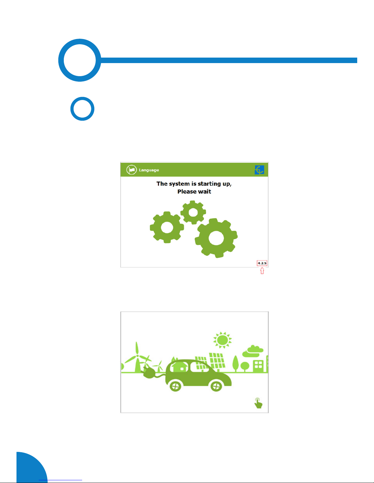
The first time the Charge Point is powered on, the system will take around 10 seconds
for starting up, the screen will show next image:
In the lower right corner, it shows the firmware version. After that 10 seconds have
passed, the first screen that appears is the screensaver,
Tap over this screen, and the HMI will skip to the next screen:
A
General
13
How to use it ?
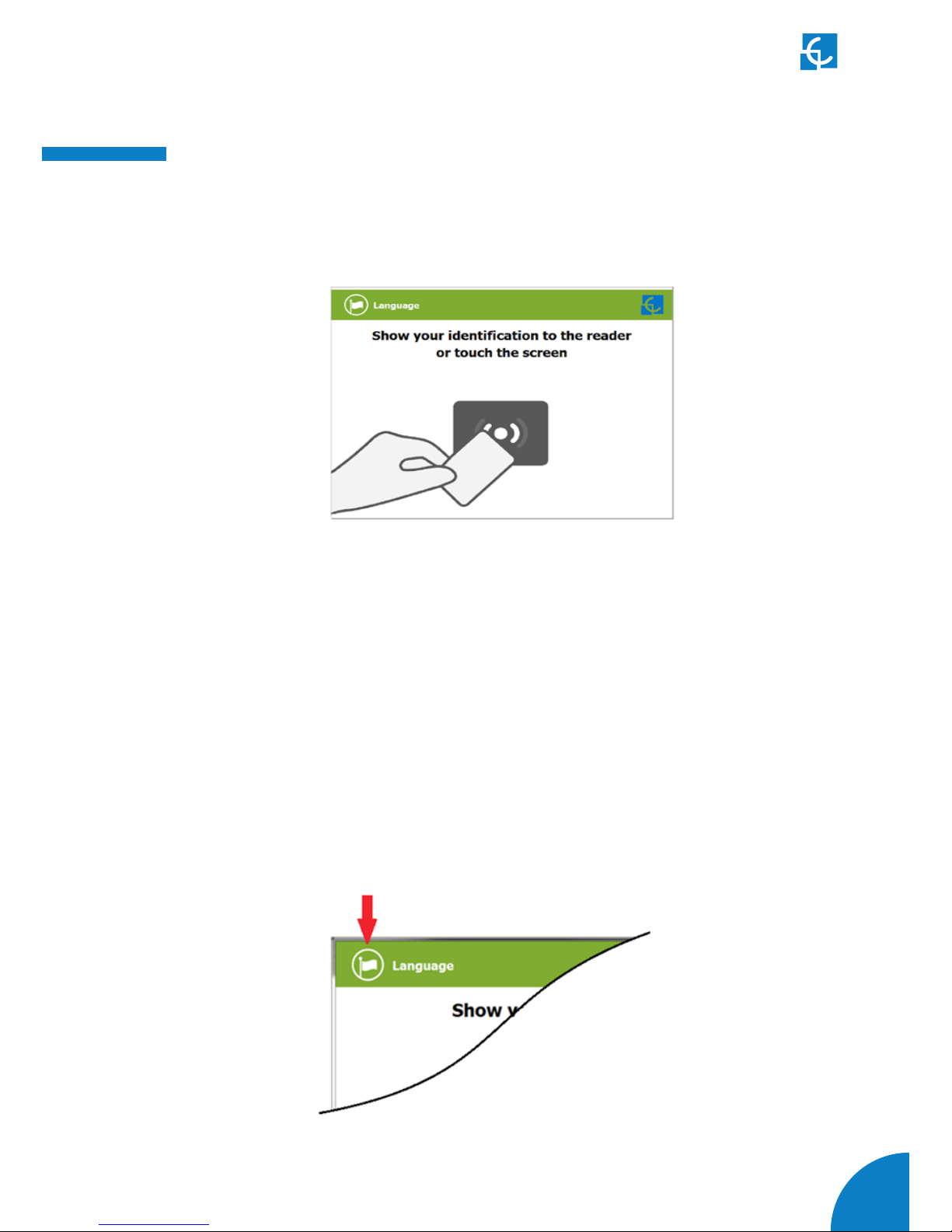
At this new screen, the Charge Point is asking for showing the identification card or
touch the screen, as you can see there are two options.
The first option, showing the identification card, is the option that will let to initiate
a “charging session” to the user that has been registered in advance or has the
identification card.
The second option, touch the screen, is only to get information about the connectors
status and the charging process so as to know the Charge Point availability but you
cannot start or do any action over the currently charging session.
Also, at this screen and during all the process is possible to change language,
pressing on the top of the screen over the “Flag” touch symbol:

14
Raption 50 Series Instruction Manual
Next screen will appear, press over your language’s flag:
It is possible to choose between next languages:
Catalan; German; English; Spanish; Finnish; French; Italian; Dutch; Norwegian;
Polish; Russian; Swedish.

15
B
Starting a charging session
- Once you have shown your identification card, the HMI will show next screen:
Wait while Charge Point performs identification
- If everything is correct and the user is authorized, the HMI will show next screen:
16
Raption 50 Series Instruction Manual
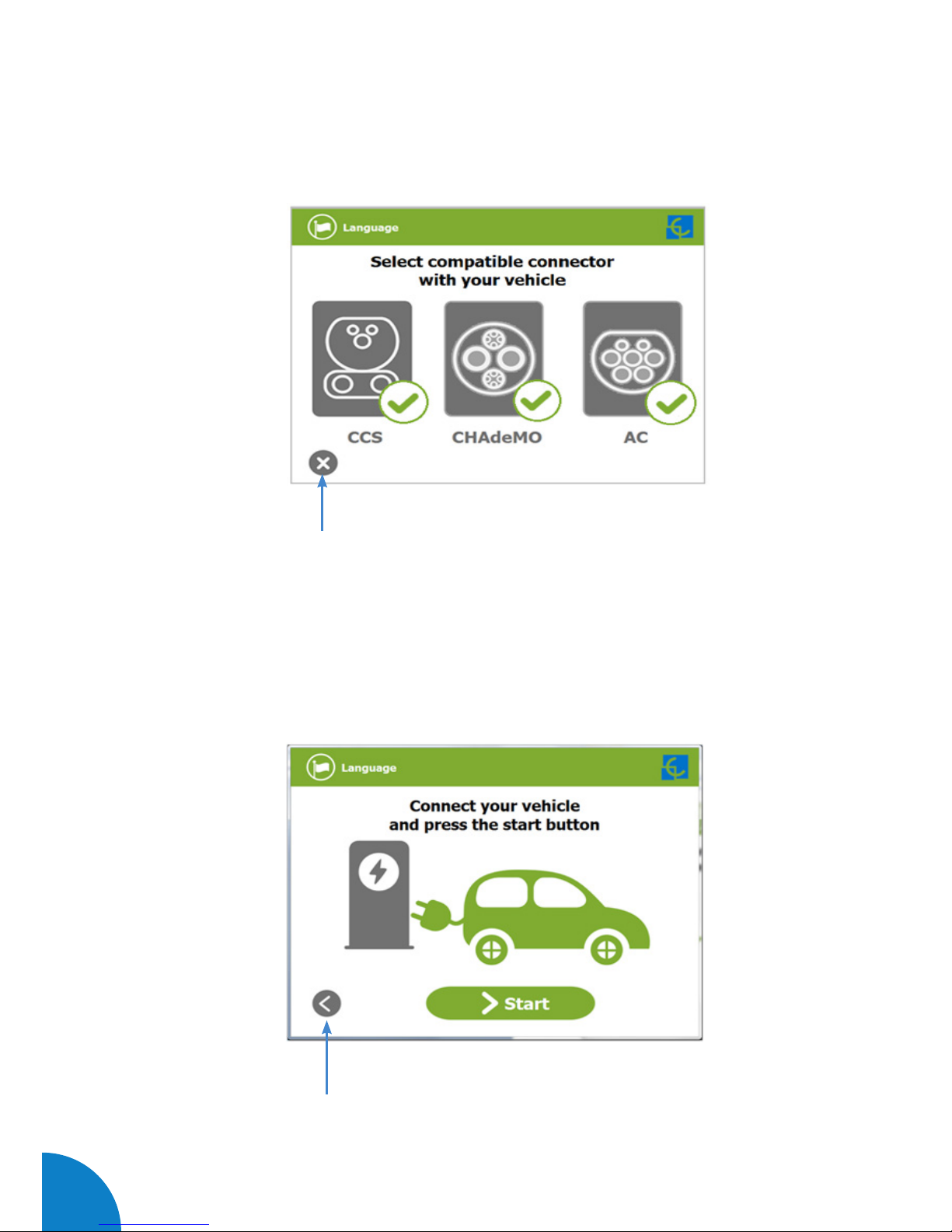
- Now, the user can choose the connector, always depending of the sort of vehicle that
you have and if the connector status is available:
At any time is possible to press over this button in order to go back to the “identification
screen”.
- Once you have chosen your connector, instruction screens will appear successively,
follow the instructions:
1- Connect your vehicle and press the “Start” button
At any time is possible to press over this button in order to go back to the previous
screen.
17
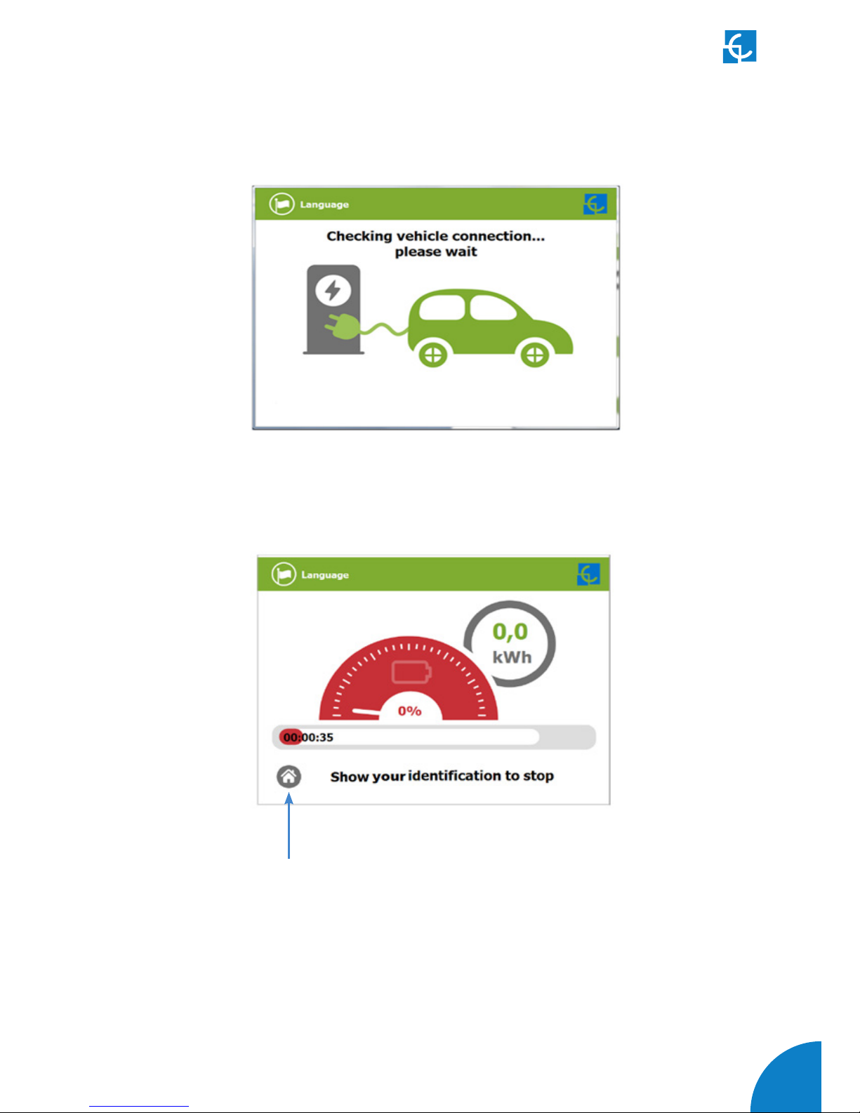
2- Checking vehicle connection… Please wait
- In a few seconds, the charging session will start and the HMI will show the charging
process.
Pressing over this button, the screen will go back to the “identification screen”.
18
Raption 50 Series Instruction Manual
C
Special events starting a charge
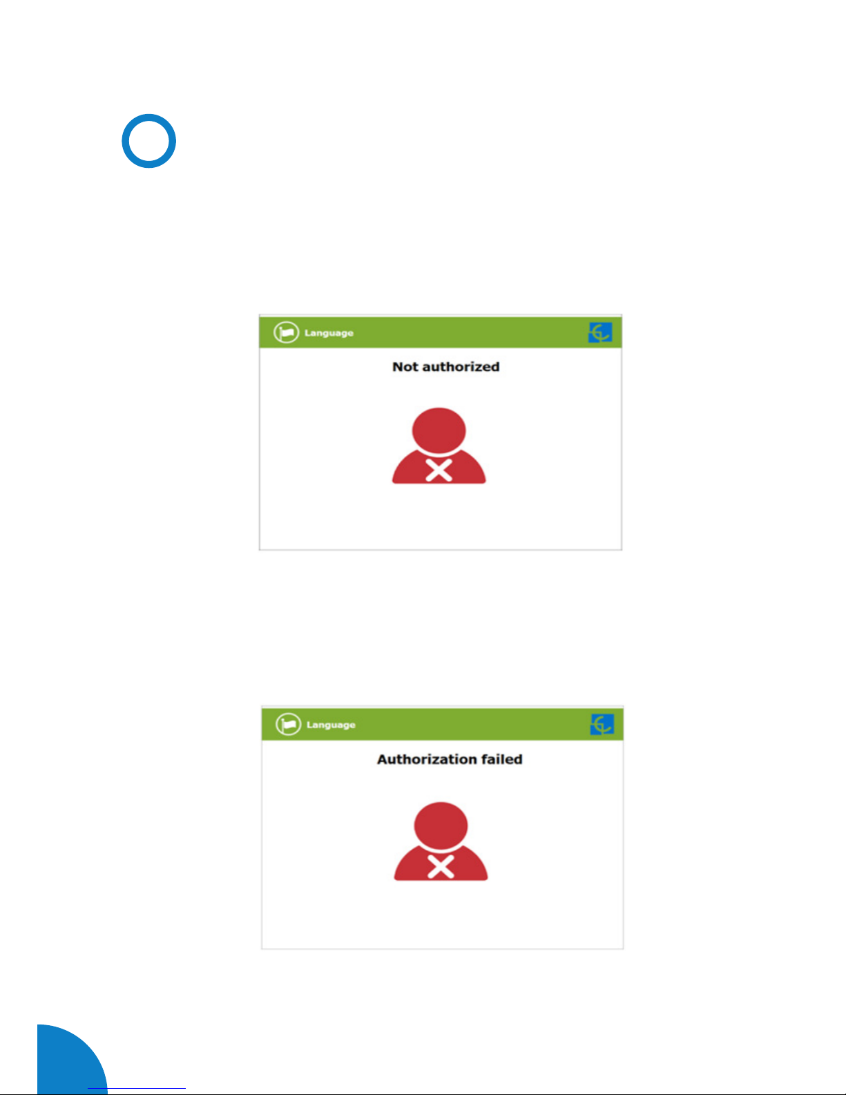
A - “Not authorized”: some Charge Points could be working under the supervision of
the main management system, called Back Office. It can generate a whitelist in order
to register new users, manage charging sessions, etc. If the user is not authorized,
the HMI will show the following message:
B - “Authorization failed”: if there is some communication problem with the Back
Office right at the connecting time:

19
C - “Not authorized, Concurrent charge”: in this case, the identifier is already
involved in another charge transaction:
D - “Not authorized, Authorization expired”: is possible that the back office has put
deadline to your identification card and this date is already expired:
20
Raption 50 Series Instruction Manual
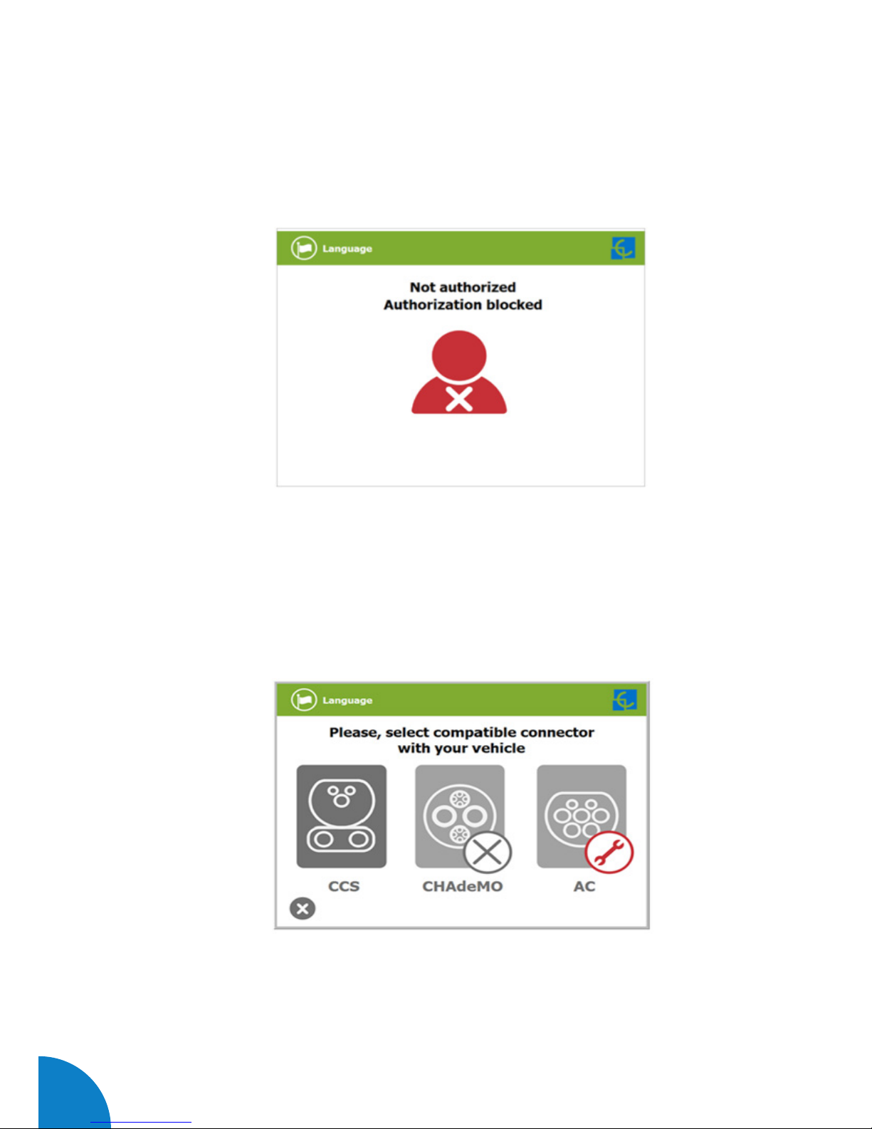
E - “Not authorized, Authorization blocked”: is possible that the back office has
blocked temporarily your identification card.
F – After the user has been properly authorized and just at the moment that has to
choose the connector, the screen will show the connectors status, it could appear
some problem. It is possible to use the connector painted in dark grey but it will be
impossible to use any connector with another symbol, like next:

21
G - Another issue that can occur is “Vehicle not detected”, unlock the connector,
connect again and press over “Retry” button.
H – Almost all vehicles cannot charge if the shift lever is not in parking mode position.
This situation can be detected for the Charge Point and it will be displayed by HMI
as “Please, check vehicle shift position, put in parking mode”, after pressing over
“Retry” button.

22
Raption 50 Series Instruction Manual
I – Is possible that the problem than appears is not a concrete one, the HMI will show
next screen, press over “Retry” button.

23
D
Stopping a charging session
- The HMI is showing the charging process and next message “Show your identification
to stop”, the session can be stopped by the same user that has started it.
- After showing your identification card, the Charge Point will allow you to stop the
charging session, press over the “Stop” touch button:

24
Raption 50 Series Instruction Manual
- Once you have stopped the charging session, the HMI will show the summary screen,
press over the “Exit” touch button and disconnect your vehicle:

25
E
Charging information
Depending of the sort of charging that it has been done either AC or DC, the HMI screen
can show different process information.
There are different information for AC (mode 3), DC (CCS) and DC (CHAdeMO); the
following images show the basic charging process information.
1 — CHARGING AC (MODE 3)
1
2
3
4
5
6
1- Language button: pressing over this button it is possible to change the HMI
language.
2- Analog process indicator: at first moment it is red, as the vehicle is charging it will
change to green, passing before for orange.
3- Charge time with status bar: charging time elapsed until now.
4- Touch button: it goes back to the “identification screen”.
5- Additional information: current status, errors, battery status, etc.
6- Energy charged: energy supplied to the vehicle so far.

26
Raption 50 Series Instruction Manual
2 — CHARGING DC (CCS)
1- Language button: pressing over this button it is possible to change the HMI
language.
2- Analog process indicator: at first moment it is red, as the vehicle is charging it will
change to green, passing before for orange.
3- Battery SOC: It indicates the current battery state of charge.
4- Charge time with status bar: charging time elapsed until now.
5- Touch button: it goes back to the “identification screen”.
6- Additional information: current status, errors, battery status, etc.
7- Remaining time until 80 %: remaining time until getting 80 % of the SOC.
8- Remaining time until 100 %: remaining time until 100 % of the SOC.
9- Energy charged: energy supplied to the vehicle so far.
1
2
3
4
5
6
7
8
9

27
3 — CHARGING DC (CHADEMO)
1- Language button: pressing over this button it is possible to change the HMI
language.
2- Analog process indicator: at first moment it is red, as the vehicle is charging it will
change to green, passing before for orange.
3- Battery SOC: It indicates the current battery state of charge.
4- Charge time with status bar: charging time elapsed until now.
5- Touch button: it goes back to the “identification screen”.
6- Additional information: current status, errors, battery status, etc.
7- Remaining time until 100 %: remaining time until 100 % of the SOC.
8- Energy charged: energy supplied to the vehicle so far.
1
2
3
4
5
6
7
8
28
Raption 50 Series Instruction Manual
F
Charging summary
The following image appears when EVs have finished charging or the session has
been interrupted by the user. There are different summary screen, depending of you
are charging on AC (mode 3) or DC (CCS / CHAdeMO).
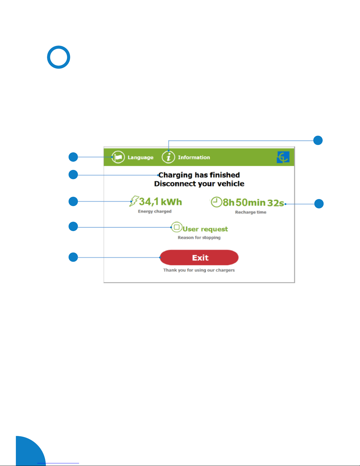
1 — SUMMARY SCREEN FOR AC (MODE 3)
1- Language button: pressing over this button it is possible to change the HMI
language.
2- Process instructions: different instructions can be displayed.
3- Energy charged: total energy charged at the end of the charging session.
4- Stop reason: It shows why the charging session has been stopped.
5- Exit button: It has to be pressed in order to finish the charging session. After
pressing, the HMI screen will go back to the “identification screen”.
6- Recharge time: total recharging time at the end of the charging session.
7- Information button: pressing over this button you can get information about the
charging session, per example the “reason for stopping” or another one.
1
4
5
2
3
6
7
29
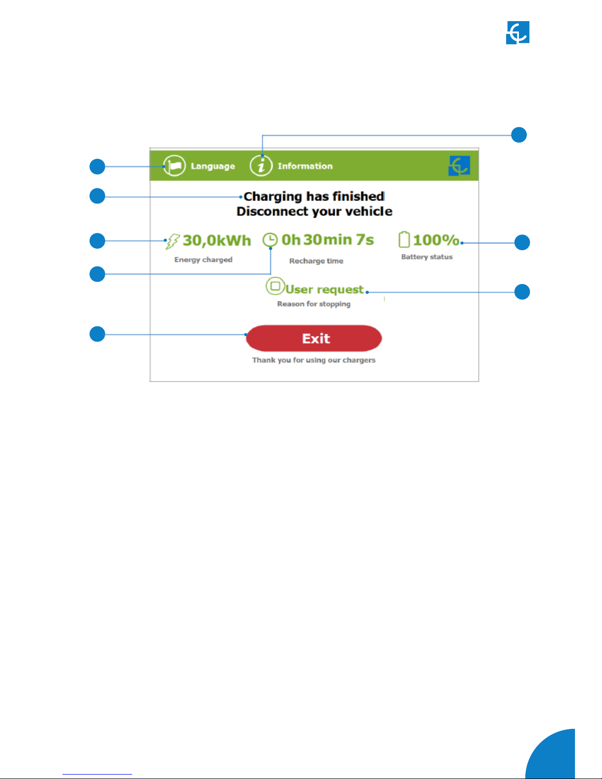
2 — SUMMARY SCREEN FOR DC (CCS / CHADEMO)
1- Language button: pressing over this button it is possible to change the HMI
language.
2- Process instructions: different instructions can be displayed.
3- Energy charged: total energy charged at the end of the charging session.
4- Recharge time: total recharging time at the end of the charging session.
5- Exit button: It has to be pressed in order to finish the charging session. After
pressing, the HMI screen will go back to the “identification screen”.
6- Stop reason: It shows why the charging session has been stopped.
7- Battery SOC: It indicates the final battery state of charge at the end of the charging
session.
8- Information button: pressing over this button you can get information about the
charging session, per example the “reason for stopping” or another one.
1
4
5
2
3
6
7
8
30
Raption 50 Series Instruction Manual
G
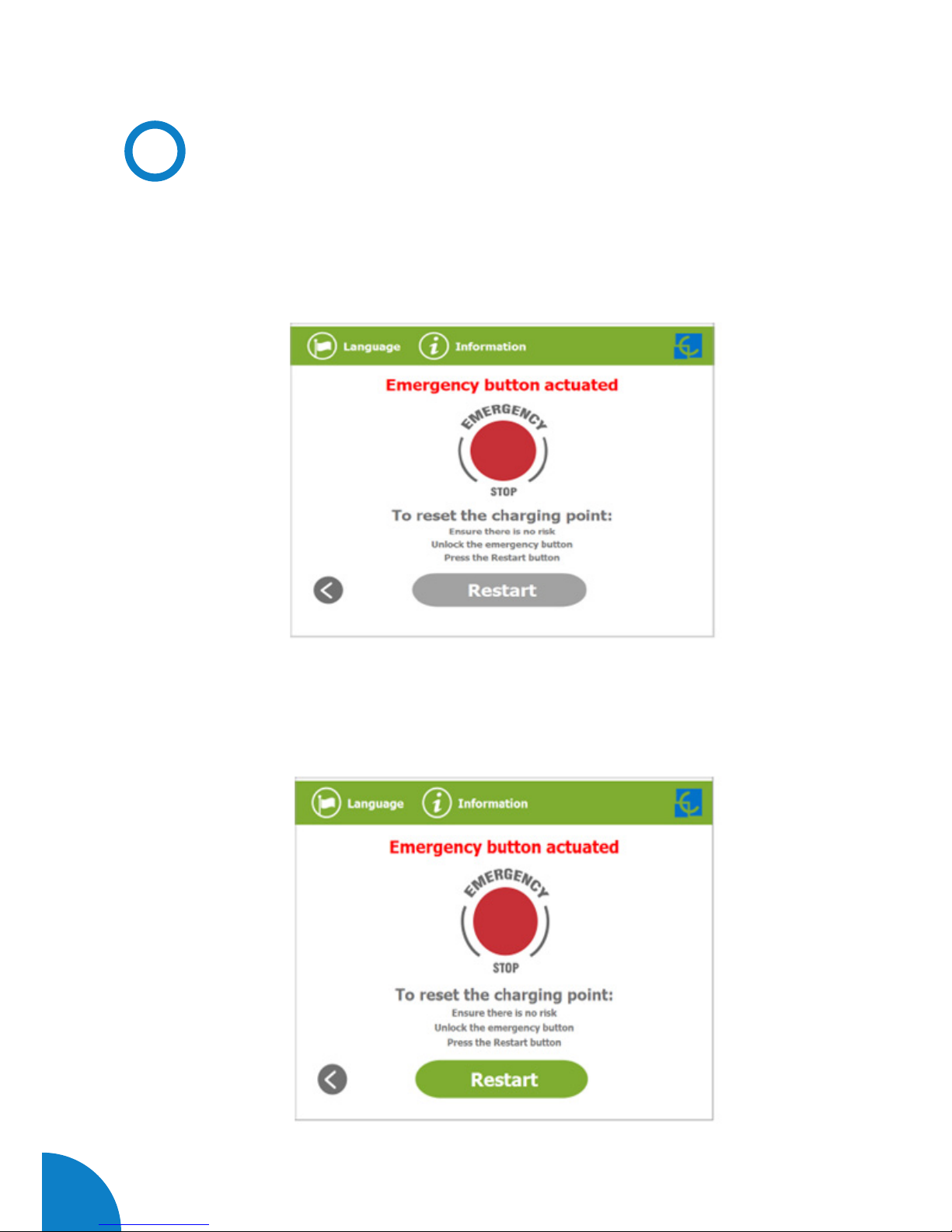
Emergency button
If for any reason the Emergency button has been pressed, the beacon lights are in
red and it will not be possible to do any charge. All the power modules will shut down
in order to protect the user and the own Charge Point. The HMI screen will remain
power up in order to show the instructions.
At first moment, the “Restart” touch button will be in grey and it will not be able for
pressing, once you have unlock the emergency button the “Restart” touch button will
be in green and able to use.

31
2 — SUMMARY SCREEN FOR DC (CCS / CHADEMO)
1- Language button: pressing over this button it is possible to change the HMI
language.
2- Process instructions: different instructions can be displayed.
3- Energy charged: total energy charged at the end of the charging session.
4- Recharge time: total recharging time at the end of the charging session.
5- Exit button: It has to be pressed in order to finish the charging session. After
pressing, the HMI screen will go back to the “identification screen”.
6- Stop reason: It shows why the charging session has been stopped.
7- Battery SOC: It indicates the final battery state of charge at the end of the charging
session.
8- Information button: pressing over this button you can get information about the
charging session, per example the “reason for stopping” or another one.
1
4
5
2
3
6
7
8
32
Raption 50 Series Instruction Manual
H
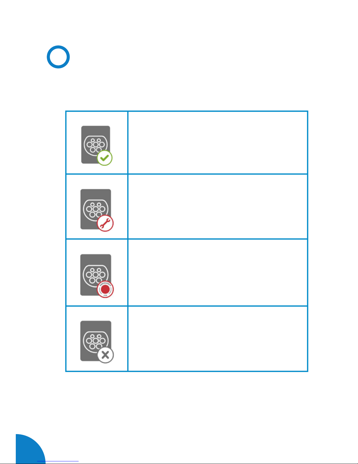
Connectors status
The HMI screen shows a different symbols over the connector pictures, as you can
see below:
- It means that there is not any problem in this connector
and is ready for use.
- This connector is out of service for any technical reason.
Press over “information” touch button in order to get
more information about it.
- The Charge Point is out of service because the
emergency button has been pressed. This fact affects all
the connectors at the same time.
- The connector is disabled. The Charge Point is out of
order due to some maintenance job or because the back
office has decided to stop it.
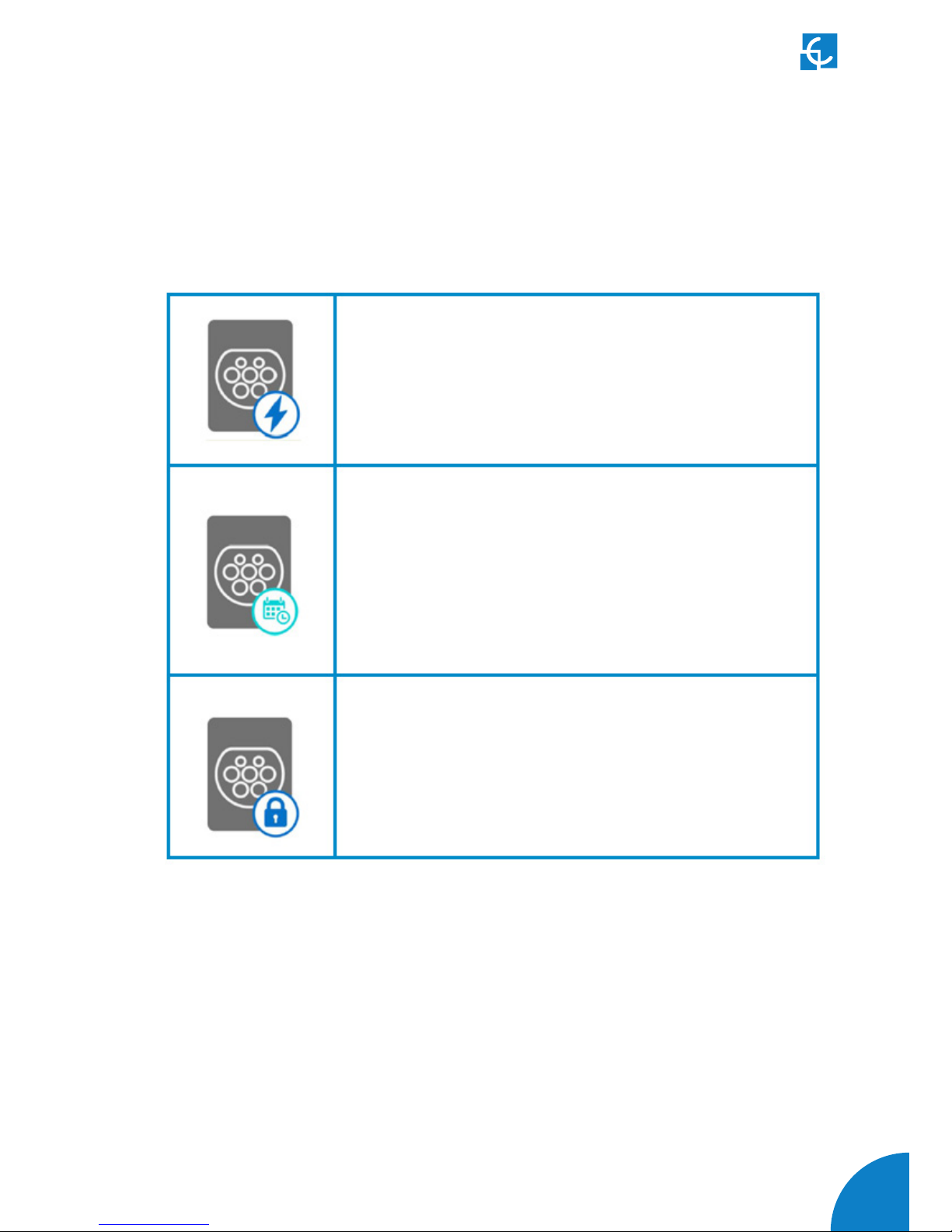
33
- The user cannot use this connector because another
user is already using it.
- This connector has been reserved and only will be able
to use per the user that has made the reserve.
NOTE: if the user that has reserved the Charge Point is
yourself the charging session will start normally, if not,
the Charge Point will not be able to charge until the date
and time displayed have expired.
- Only for DC connectors. As the Charge Point only can
performance one DC charging session at the same time,
CCS or CHAdeMO, it could be possible to find one of
these connectors with this symbol because the other is
charging or has been reserved.

34
Raption 50 Series Instruction Manual
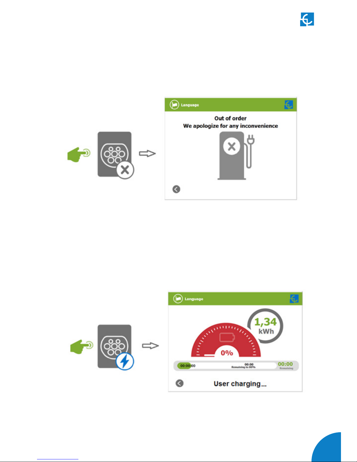
I
Consulting the connectors status
It is possible to press over each connector picture to get more information about the
status:
1 — CONNECTOR ABLE
2 — ERROR CONNECTOR
35
3 — CONNECTOR DISABLE
4 — CONNECTOR IN USE
36
Raption 50 Series Instruction Manual
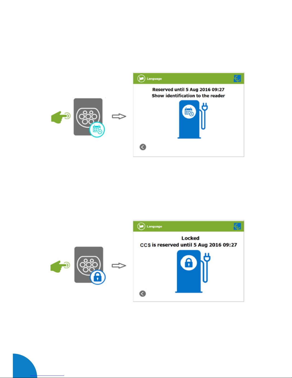
5 — CONNECTOR RESERVED
6 — CONNECTOR BLOCKED PER RESERVED
37
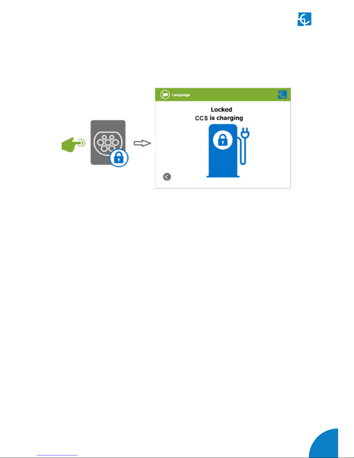
7 — CONNECTOR BLOCKED PER CHARGING

38
Raption 50 Series Instruction Manual
J
Errors
The Charge Point can report about different sort of errors, it can be from different
parts or devices from it.
When the “error screen” appears, the “Information” touch button has to be pressed
in order to see the error message, as you can see below:

39

40
Raption 50 Series Instruction Manual
4
The Charge Point can be configured and monitored to establish owner preferences
or specific setup using integrated Ethernet communication port allocated in HMI
screen device.
Once service PC is configured as bellow procedure and connection established with
the Charge Point, direct access to the main setup page will be showed.
The Charge Point is shipped from the factory with default network setting of “DHCP
enabled”. It means that the Charge Point will try to obtain an IP address from a DHCP
server available on the network.
Step by step below guide detailed setup an IP address to the Charge Point in case
there is no DHCP server available on the network.
A
Introduction

41
How to
configure it ?
Below table shows, hardware and software needed to setup and IP address to the
Charge Point.
B
What’s needed?
- Computer running Microsoft Windows, at least Windows
XP .
- UTP Cable (Crossover recommended)
- IPSetup.exe (*)
- CirCarLife Scada Client (*)
(*) In order to get the software needed, you can download it from http://circontrol.
com/downloads/ or contact with ps-support@circontrol.com

42
Raption 50 Series Instruction Manual
C
Network topology
Connecting the service PC with Charge Point needs to be done with static IP address
and TCP/IP v4 protocol.
Next section shows how to do this configuration. Below image shows Ethernet
connection topology and the IP addresses used in this guide as example.
For laptop > IP: 192.168.1.10 NETMASK: 255.255.255.0
For Charge Point > IP: 192.168.1.11 NETMASK: 255.255.255.0

43
D
LAN connection procedure
This section provides a step-by-step guide to connect the service PC to the Charge
Point in order to see real-time status.
1- Click on the network icon next to the clock of the taskbar, and Click on > “Open
Network and Sharing Center”
2- On the left pane, click on > “Change adapter settings”
44
Raption 50 Series Instruction Manual
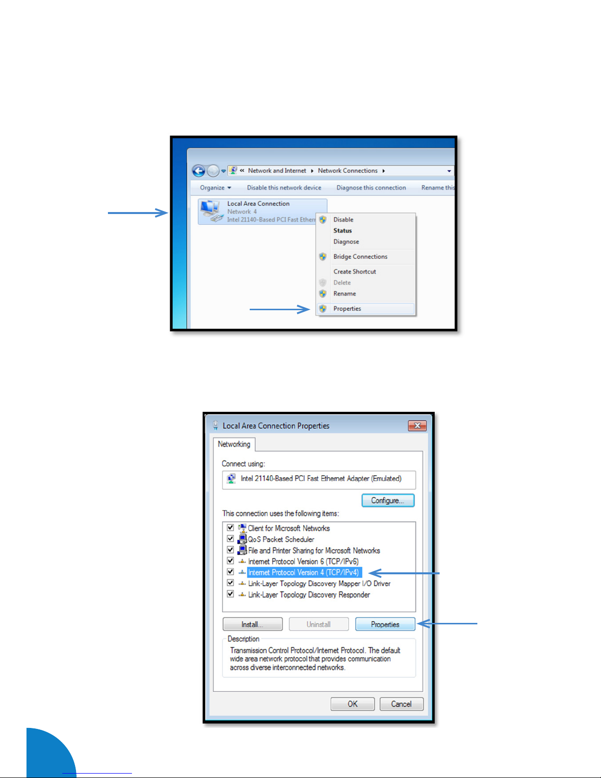
3- Make right click on > “Local Area Connection” and then click on > “Properties”
4- Select “Internet Protocol Version 4 (TCP/IP)” option and click on > “Properties”
45
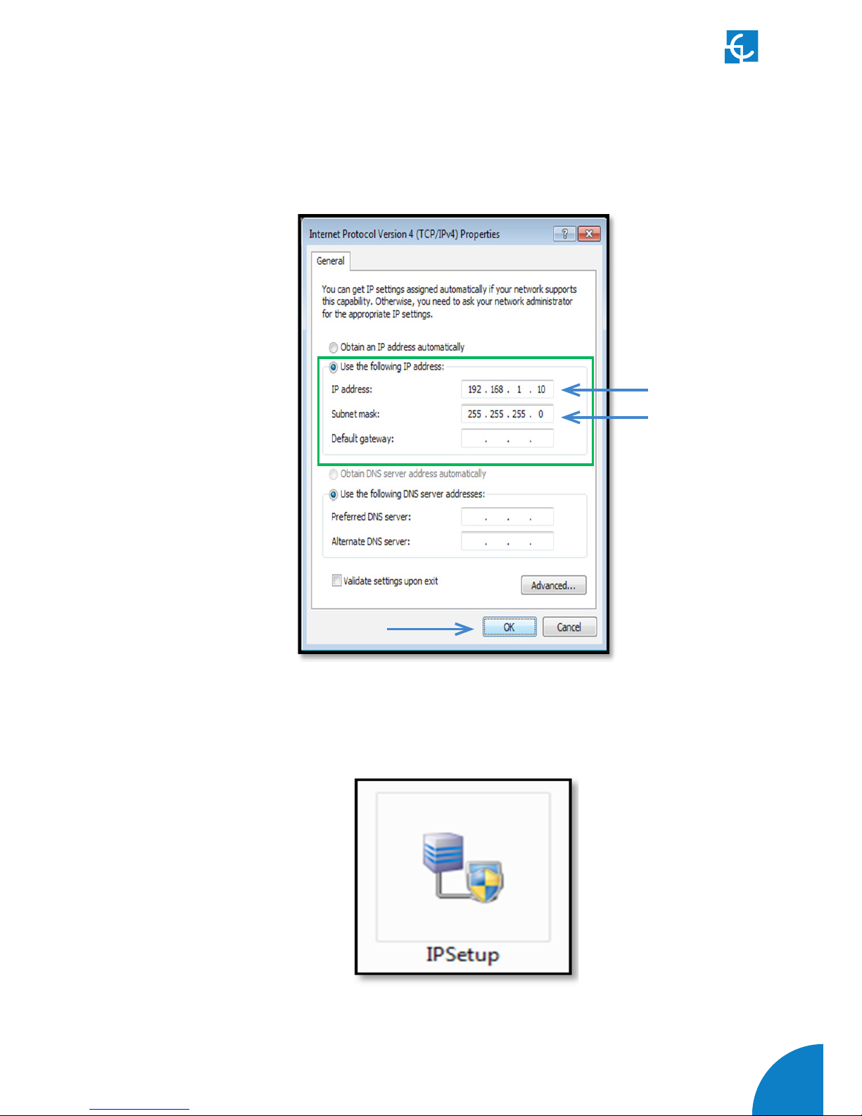
5- Setup IP address and subnet mask like as shown here below and click “OK” twice to
complete the assigning IP address process to the computer.
6- Execute > IPSetup.exe on the service PC
46
Raption 50 Series Instruction Manual
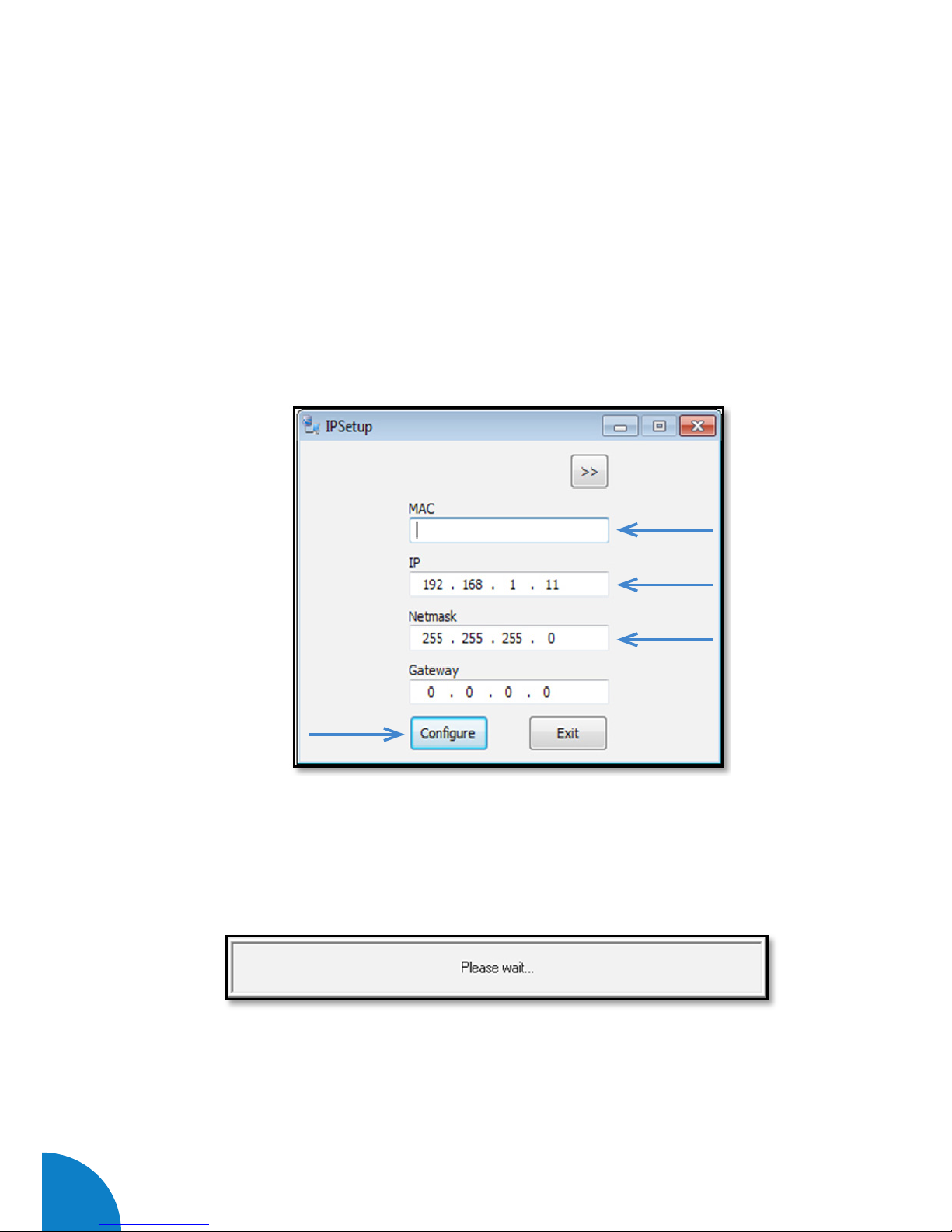
7- Enter the following parameters and click on > “Configure”
• MAC of the Charge Point (see label on the screen)
• IP address: i.e.(192.168.1.11)
• Netmask: i.e. (255.255.255.0)
• Gateway: leave default settings.
8- Wait 30 seconds approximately until the process is complete.

47
9- The process will complete when the following message appears, click on > “OK”
10- If the message shown is the next one, check the following parameters and click on
> “OK”
• Check IP address entered.
• Check the MAC of the device entered.
• Try with another UTP CAT5e cable.
48
Raption 50 Series Instruction Manual
E
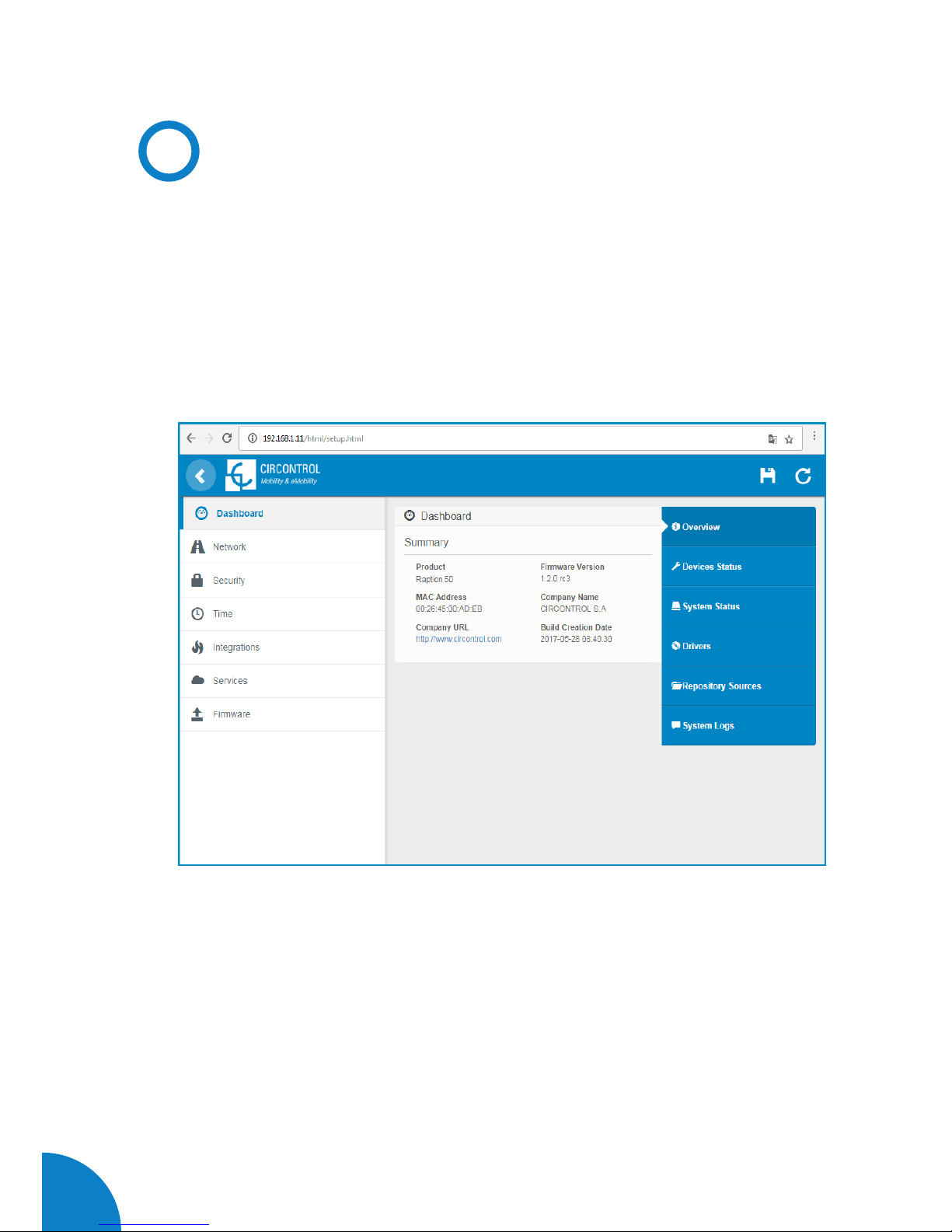
Setup Webpage
Setup webpage allows managing networking setup, upgrading devices and other
options.
Once the service PC is already connected with Charge Point, it is possible to go
inside de Setup Webpage throug the IP. In the example shown above, it has been set
192.168.1.11.
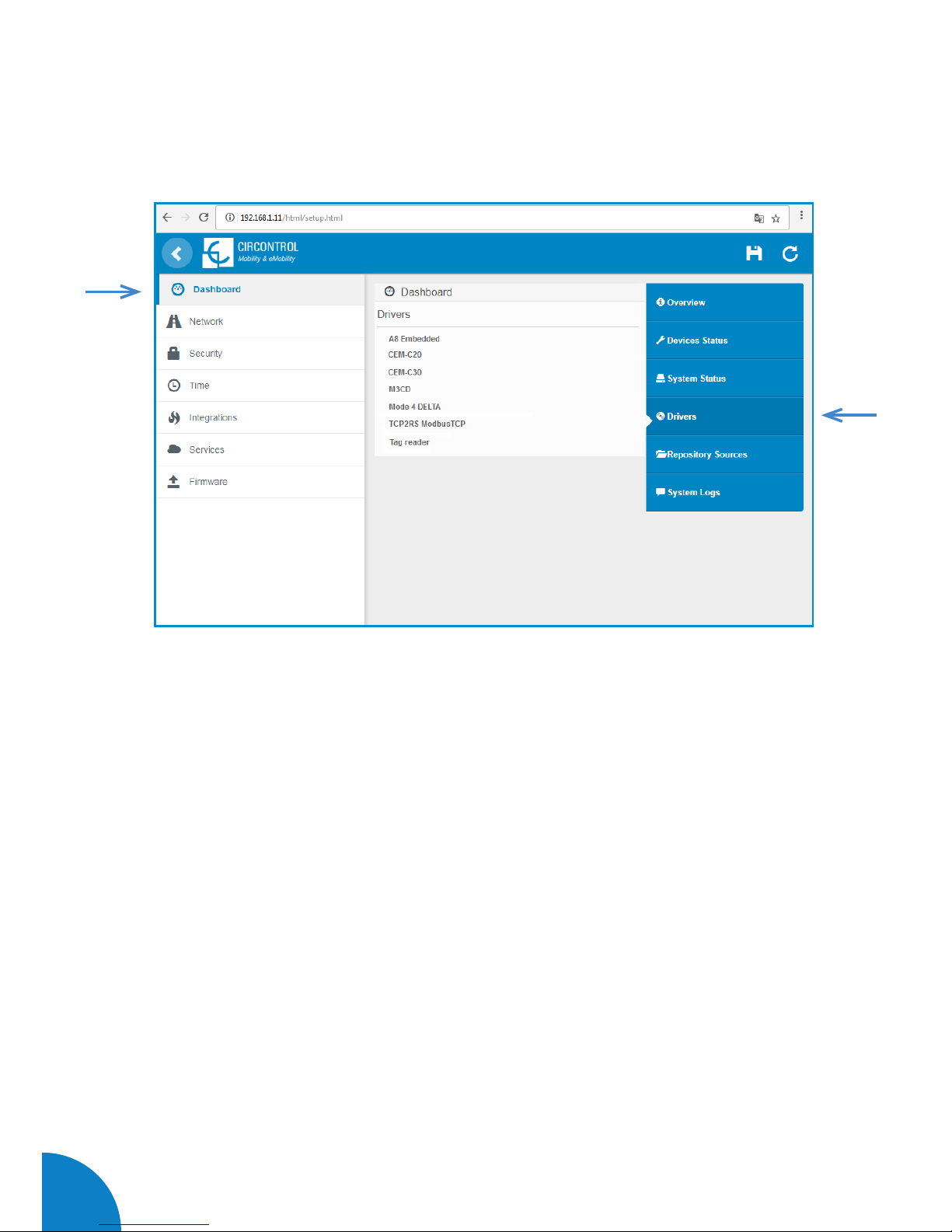
The webpage opened shows the ‘Dasboard’ Overview as a main screen, but, there are
many more options. In the next points, it will be explained.

49
Value Description
Firmware version Version of the firmware currently working in the Charge
Point
MAC Address Identifier of the network card of the Charge Point
As a relevant information, the ‘Summary’ shows:
A)
Dashboard
OVERVIEW
50
Raption 50 Series Instruction Manual
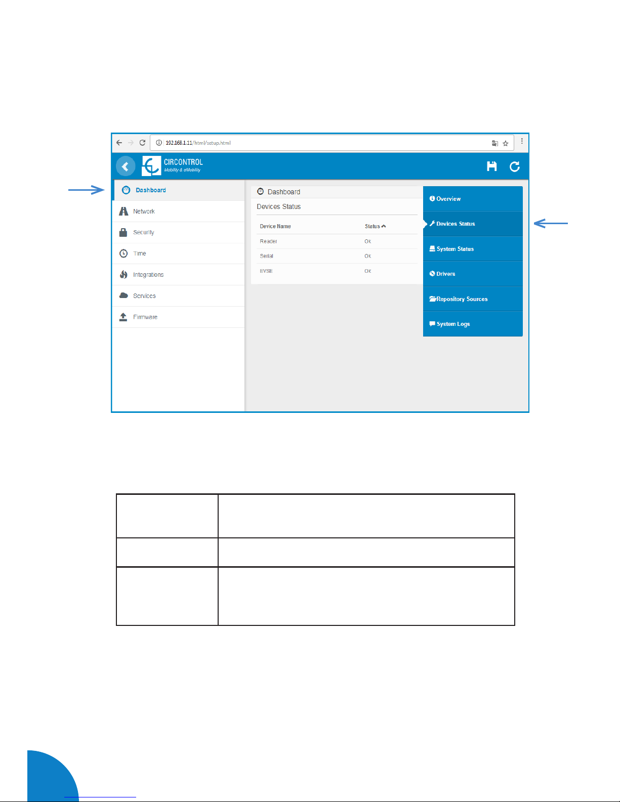
DEVICES STATUS
As a relevant information, the ‘Devices Status’ shows:
Value Description
Device name Name of the devices inside the Charge Point
Status
OK: online
NOT OK: offline
51
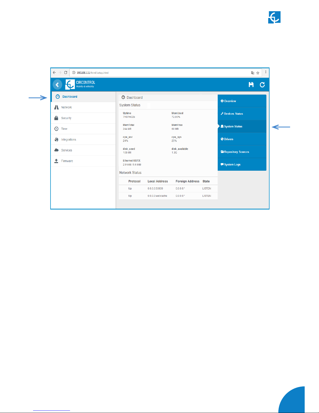
- The information shown in this section is basically relative to the state of the PC of
the Charge Point, it is necessary for the technical service staff but does not show any
information regarding the external connection of the Charge Point or regard to the
charging session.
SYSTEM STATUS
52
Raption 50 Series Instruction Manual
- The information shown in this section is regard to the drivers that the Charge Point
needs in order to recognize the different devices inside the Charge Point, such as the
meters, the mode 3, the RFID reader, etc.
DRIVERS

53
REPOSITORY SOURCES
- The information shown in this section is basically related to the internal behavior of
the Charge Point, it is necessary for the technical service staff but does not show any
information about the external connection of the Charge Point or with respect to the
charging session.

54
Raption 50 Series Instruction Manual
- The logs shown in this section are automatically produced by the Charge Point, it is a
detailed list of the charging session, system performance, or user activities.
This logs are created since Charge Point is powered On. If Charge Point is restarted
this logs are erased and immediately is created a new one.
SYSTEM LOGS

55
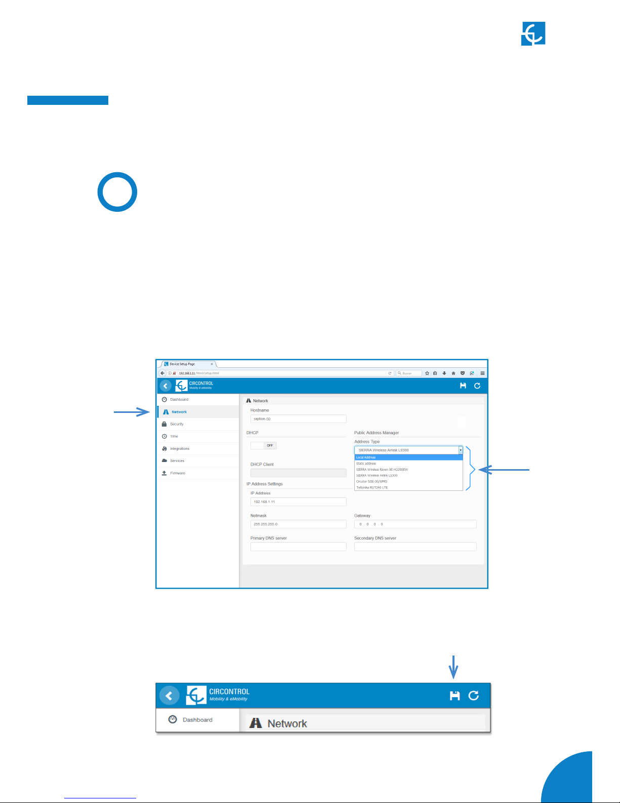
B)
Network
This section provides basic configuration of the network parameters. Clicking over
the ‘Network’ tab, next image will appear.
Value Description
Hostname Name of the Charge Point on the network
Next, we will explain the different sections of the 'Network'

56
Raption 50 Series Instruction Manual
Value Description
Address Type
• Local address: select this option if the OCPP
central system is connected to the same private network
than the charge point is already connected. It is assigned to
the Ethernet Port.
• Static address: select this option if the external
modem/router is different than listed below. It must have
static public IP address, check it with your SIM provider.
Note: Public IP address must be entered manually in the
“Public IP” text box.
• SIERRA Wireless Raven XE H2295EW: Select this
option only when SIERRA Wireless RAVEN XE cellular
router is connected to the charge point.
• SIERRA Wireless AirLink LS300: Select this option
only when SIERRA Wireless AirLink LS300 cellular router
is connected to the charge point.
• Circutor SGE-3G/GPRS: Select this option only
when Circutor SGE-3G/GPRS cellular router is connected
to the charge point.
• Teltonika RUT240 LTE: Select this option only
when Teltonika RUT240 LTE cellular router is connected to
the charge point.
DHCP Client ID Client ID associated to the DHCP server (if available)
Public IP Static public IP address to write if provided by the SIM
provider
IP Address IP Address assigned to the Charge Point
Netmask Netmask of the network
Gateway Gateway of the network

57
C)
Security
This section provides basic configuration of the security parameters. Avoiding
unauthorised access to the Setup Webpage. All parameters are disable from factory
settings.
Clicking over the ‘Security’ tab, next image will appear.
Next, we will explain the different sections of the 'Security'
Value Description
Authentication ON: authentication enableb OFF: authentication disabled
User Name
Username and Password authentication for Setup web pagePassword
Repeat password
Note: do not forget the credentials. There is no way to restart the Charge Point to
default factory settings.

58
Raption 50 Series Instruction Manual
D)
Time
This section allows setting the time and region time for the Charge Point.
Clicking over the ‘Time’ tab, next image will appear.
Next, we will explain the different sections of the 'Time'
Value Description
Time Zone Select the regional time for the Charge Point according
to the location
Time Current date and time of the Charge Point
Primary NTP Server Synchronize the time through internet automatically
Secondary NTP
Server

59
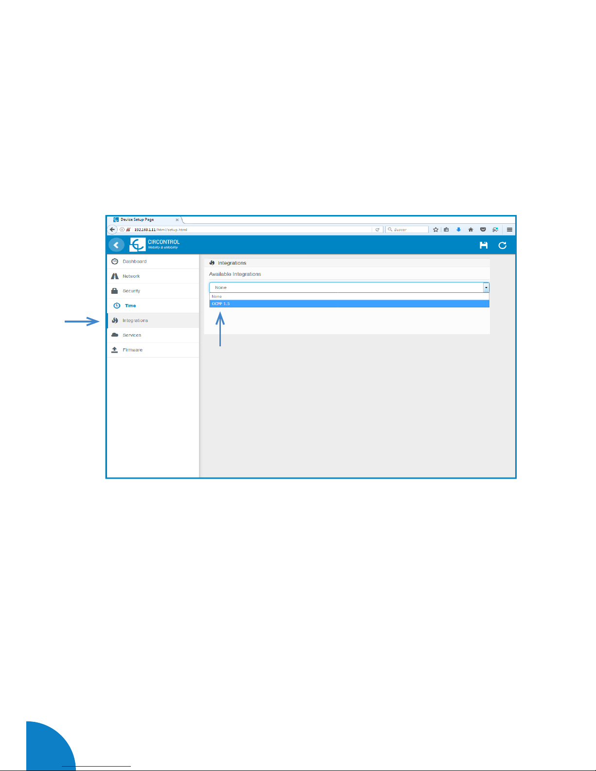
E)
Integrations
Clicking over the ‘Integrations’ tab, next image will appear.
Note:
The integration of the Charge Point deserves a separate chapter. In the next chapter
number 5 we will explain how to integrate OCPP.
60
Raption 50 Series Instruction Manual
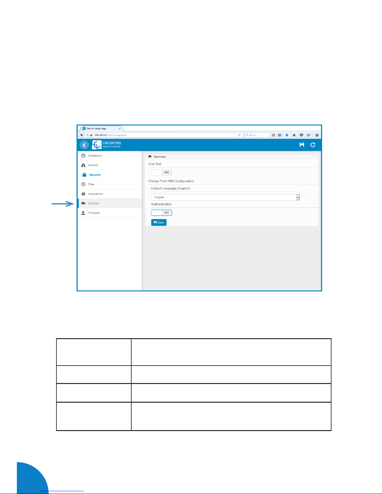
F)
Services
The main opcion at this section allows to change the HMI language and also make a
Grid test as well as setting a password.
Clicking over the ‘Services’ tab, next image will appear.
Next, we will explain the different sections of the 'Services'
Value Description
Grid Test The Charge Point makes a calibration test on the HMI screen
Default language It is possible to choose the default language for the HMI
Authentication It can be set an authentication for avoinding changes in this
page

61
G)
Firmware
Through ‘Firmware’ tab, the Charge Point firmware can be upgraded remotely.
The upgrading firmware is suplly for CIRCONTROL Post Sales Support department.
Clicking over the ‘Select File’ tab, a new pop up window will be open in order to
choose the upgrading file.
Choose the file provided for Post Sales Support department and wait for the process.

62
Raption 50 Series Instruction Manual
5
The goal for the Open Charge Point Protocol (OCPP) is to offer a uniform solution
for the method of communication between charge point and central system. With
this protocol it is possible to connect any central system with any charge point,
regardless of the vendor.
Follow next steps in order to configure the OCPP in the Circontrol Charge Points.
A
Introduction
63
OCPP
Integrations
A) At ‘Network’ tab
Public Address Manager establishes where the Charge Point must obtain the public
IP address in order to send it later to the backend. Different values can be selected
in the ‘Address Type’ section:
B
Previous requirements
Choose the option selected under Address Type according to your network typology.
Check following steps in order to ensure the correct function of OCPP :
When done, please do not forget to save changes using save button in the upper right
64
Raption 50 Series Instruction Manual
B) At ‘Integrations’ tab
Charge Point supports different versions of OCPP but only one can be enabled at the
same time.
Go back to setup web page and click on the ‘Integrations’ tab, choose the option
selected under ‘Available integrations’ according to your backend policies as shown
Note:
Charge point is working as stand-alone if “none” option is selected. All ID cards are
authorized to start/stop a new charge transaction and no requests are sent to the

65
C
Starting up configuration
A) Setup Page
Once you have chosen your OCPP option at the previous step, a link appears allowing
access to the OCPP configuration.
Please, click on the link button as shown in the picture:
New tabs are opened to show OCPP Settings. First time is running the integration
selected on the charge point, it starts as configuration mode and all fields are empty.
Settings are always stored even when the Charge Point is powered off or even the
integration is disabled/stopped.
66
Raption 50 Series Instruction Manual
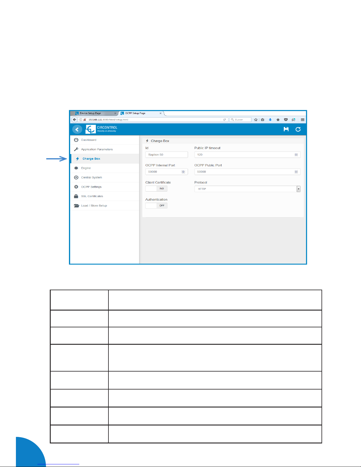
B) At ‘Charge Box’ tab
Check Charge Box Identity and the incoming ports according to the backend policies,
please contact to the Central System to get the configuration parameters:
Value Description
ID Charge Point identifier
Public IP timeout Maximum waiting time to obtain the public IP address of the 3G modem
OCPP Internal
port
Incoming listening port for remote request (internal)
OCPP Public port Incoming listening port for remote request (public)
Client Certificate Provided by the Central System
Protocol If HTTPS is selected, make sure to have CS Server CA certificate
Authentication Set an authentication if is required
67
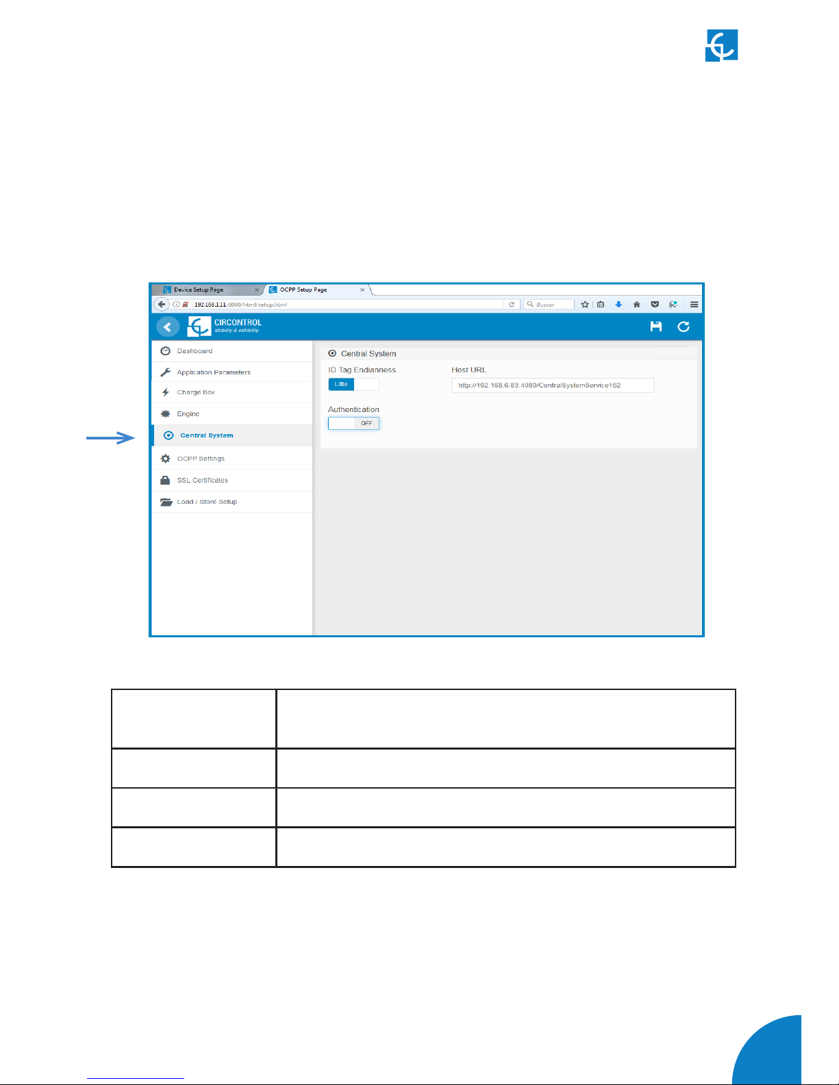
C) At ‘Central system’ tab
Allows the Charge Point to know where the central system is hosted to notify all the
requests.
Check Central System URL according to the backend policies, please contact to the
Value Description
ID Tag Endianness Storage type for system data
Host URL URL address of the central system
Authentication It can be set an authentication for avoinding changes in this page
68
Raption 50 Series Instruction Manual
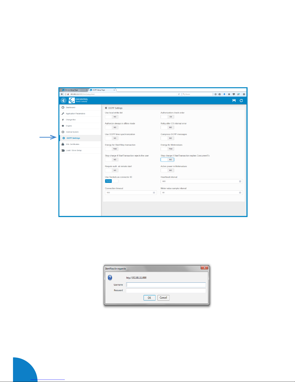
D) At ‘OCPP Settings’ tab
Check OCPP Settings according to the backend policies, please contact to the Central
System to get the configuration parameters:
Before making any changes read following table and set each option according to your
backend provider.
Note:
If any Authentication has been set at the previous steps, the system is going to ask for
this:

69
Value Description
Use local white-list
Yes: local list of authorized users -> Enabled
No: local list of authorized users -> Disabled
Authorization check order
Local: ID authorization has first place on the local white-
-list. If the user does not exist locally, then in second
place backend is asked to obtain the authorization.
CS: ID authorization is always asked to the backend.
NOTE: This setting only applies when Charge Point is
online; otherwise the authorization is only locally.
Authorize always in offline
mode
Yes: If user is not present locally in the local white-list
and charge point cannot ask to the backend, user is
allowed to start a new charge transaction.
No: If user is not present locally in the local white-list
and charge point cannot ask to the backend, the user is
not allowed to start a new charge transaction.
Retry after CS internal error
Yes: Enabled. If StatusNotification, StartNotification
or StopNotification are not received correctly by the
backend, charge point retries again to send those
requests until it is received correctly.
No: Disabled.
NOTE: Special development must be done in backend in
order to retry the messages by charge point.

70
Raption 50 Series Instruction Manual
Value Description
Use OCPP time synchronization
Yes: Synchronization of date and time -> Enabled.
No: Synchronization of date and time -> Disabled.
NOTE: Date and Time is sent from backend on each
heartbeat response.
Compress OCPP messages
Yes: Compress messages between Charge point and
backend -> Enabled.
No: Compress messages between Charge point and
backend -> Disabled.
NOTE: Before enabling this option consult to your
backend administrator if central system allows this
function.
Energy for Start/Stop
transaction
Partial: Consumed value of energy by the vehicle sent
between start and stop.
Total: actual count of the total accumulated energy
meter sent between start and stop.
Energy for MeterValues
Partial: Sends partial energy consumption while vehicle
is charging.
Total: sends the actual count of the total accumulated
energy meter.
Stop charge if StartTransaction
rejects the user
Yes: Stop existing charge transaction after response
from backend (StartTransaction.conf) when user is
blocked, expired or Invalid.
No: Charge transaction does not stops even if backend
rejects the user. (StartTransaction.conf)
NOTE: Set this option according to your backend system.

71
Value Description
Stop charge if
StartTransaction replies
ConcurrentTx
Yes: Stop existing charge transaction after response
from backend (StartTransaction.conf) when user has
already involved in another transaction.
No: Charge transaction does not stops even if backend
rejects the user. (StartTransaction.conf)
NOTE: Set this option according to your backend system.
Require auth. At remote Start
Yes: Charge point sends an authorization request before
starting a new remote charge transaction request.
No: Charge point starts a new remote charge transaction
without authorization request.
Active Power in MeterValues
Yes: Send power (Power.Active.Import) and energy
(Energy.Active.Import.Register) consumed by the
vehicle within meter values requests.
No: Only energy consumed is sent within meter values
request.
Heartbeat interval Heartbeat send interval (in seconds) for the back-end
system.
Connection timeout Timeout (in seconds) before connecting to the central
system.
Meter value sample interval
Meter value sample send interval (in seconds) during
charge transaction.
NOTE: Meter values are disabled if 0 seconds is set

72
Raption 50 Series Instruction Manual
When done, please do not forget to save changes using save button in the upper right
bar:
Please, wait until the new configuration is being applied to the Charge Point. A
message is displayed informing the progress:

73
D
Checking configuration
After applying new settings, please go to next URL from charge point in order to
check properly connection from the integration chosen:
http://<IP>/services/cpi/log?app=ocpp1.5
If “CB boot notification: success” appears then charge point is properly connected
to the back-end.
Otherwise if “Registering CB in the CS: failed” is shown then check following items:
- Backend URL. Case sensitive. Check all the URL is correct.
- Charge Point ID. Case sensitive. Check if the name entered is same as
backend expects to receive.
- Connectivity. Check if modem is power up and connected to the HMI screen.
Ask to the backend provider if any request has been received from the charge point
(BootNotification, StatusNotification or HeartBeat) after upgrading.
Look especially for the following messages:

74
Raption 50 Series Instruction Manual
6
This section describes how to install the SIM card into the unit’s 3G modem.
1 — 3G MODEM LOCATION
The modem is installed inside the unit and the antenna is fixed outside, right on the
roof of the unit.
Step 1
Step 2
Steps:
1- Open the right door of the Charge Point and locate the 3G modem right on the rear
side.
2- Check that the Charge Point is provided with the 3G antenna on the cover top.

75
3G
Communications
2 — MODEM OVERVIEW
The 3G modem installed from factory in the unit is:
Sierra Wireless AirLink LS300
This device allows to the Charge Point connects over 3G networks to remotely view or
manage the Charge Point status.
3 — MODEM INSTALLATION
Before installing the SIM card into the modem, make sure you have unplugged the
power cord from the modem.
The following schematic explains in detail the proper installation of the SIM card:
NOTE: SIM card not provided with equipment.
76
Raption 50 Series Instruction Manual
4 — MODEM CONFIGURATION
Plug again the power supply for the modem.
NOTE: After plugging back the modem, it can take until 5 minutes to respond.
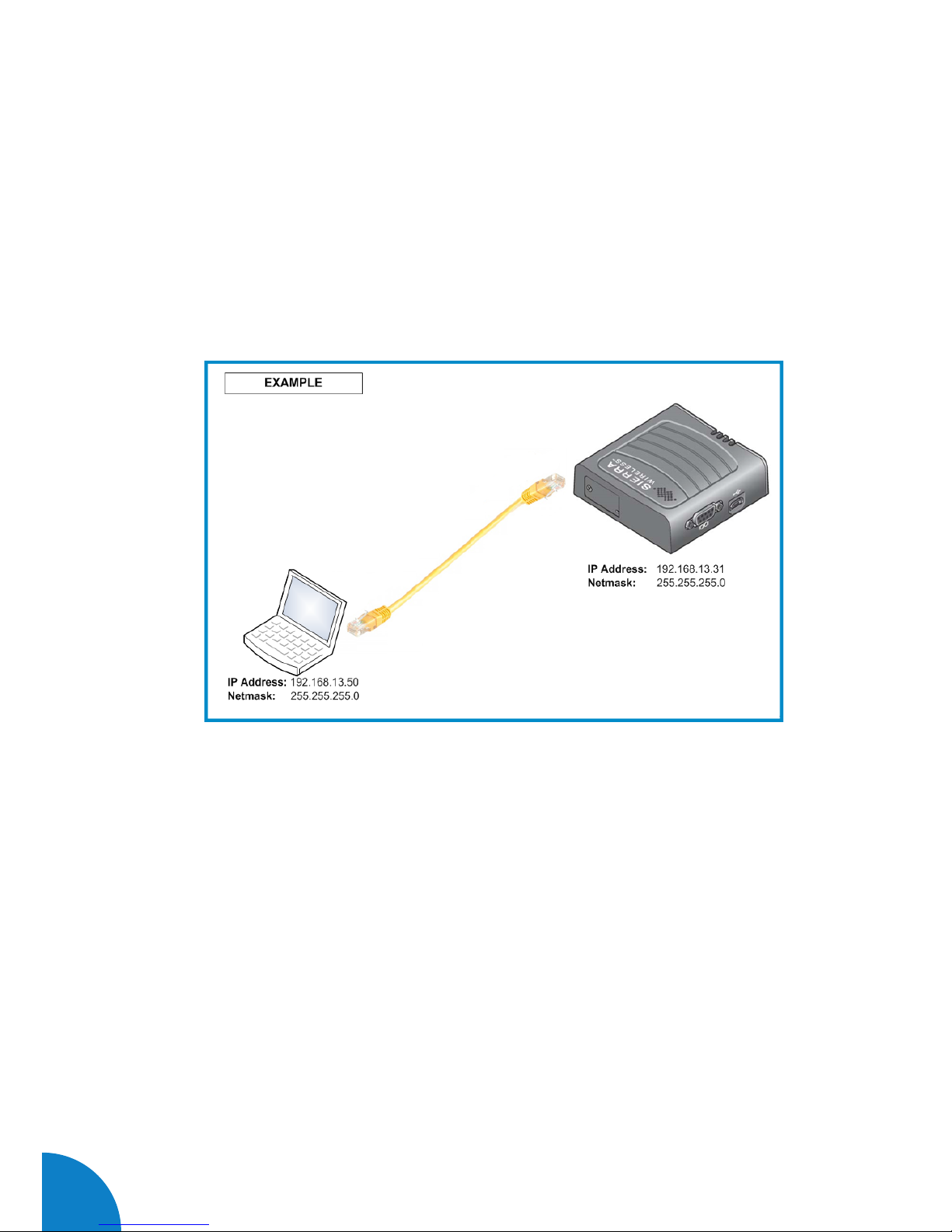
3G modem configuration is performed using the Ethernet interface. Connect your
laptop using an Ethernet cable as shown in the following image:
Set the 192.168.13.50 IP on your laptop, following the previous Chapter ‘4-D’ -->
-LAN Connection procedure -

77
Steps:
1- Open a web browser in the computer and enter http://192.168.13.31:9191. Wait
until ACE manager login screen appears.
Default username is ‘user’ and default password is ‘12345’. Do not change the
default credentials; the Charge Point requires consulting information from the 3G
modem.
2- The ACE manager homepage appears. You can now configure each device with ACE
manager. Make click over ‘WAN/Cellular’ tab.

78
Raption 50 Series Instruction Manual
3- Once clicking over ‘WAN/Cellular’ tab, introduce the ‘APN’ provided by the SIM’s
company. In case of ‘User ID’ and ‘Password’ are required too, it has to be added in
the ‘Advanced’ section.
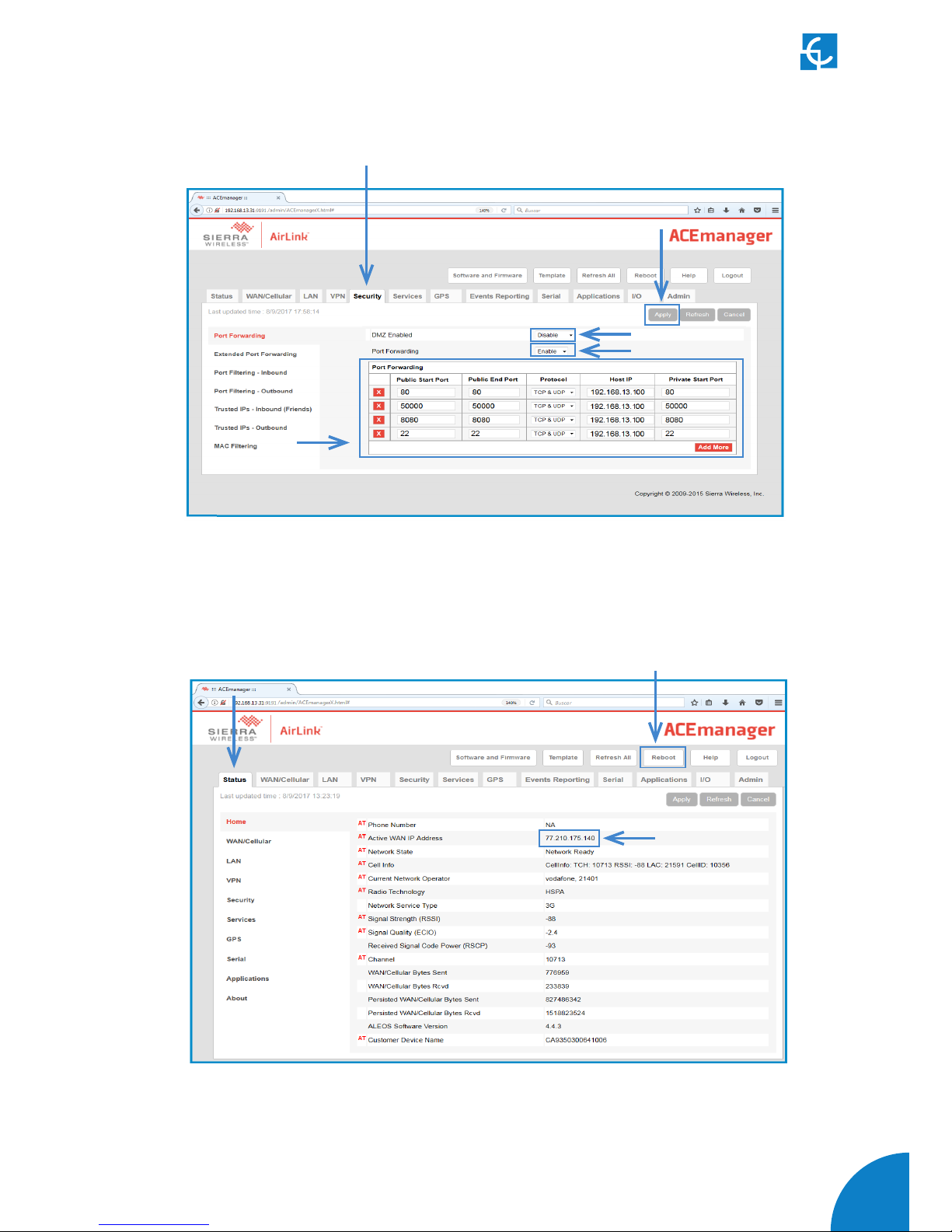
4- In the ‘Security’ tab, the ‘DMZ Enabled’ must be ‘Disable’, while the ‘Port
Forwarding’ must be ‘Enable’. Then, you will need to add the ports used by the
charger. These ports are next:
Setup Webpage OCPP Incoming
listening ports *
OCPP Settings SCP Remote
Access
80 50000 8080 22
Note:
The OCPP Listening port is 50000 by default. If your Central System works with a
different port, add it instead. You will need to configure it afterwards in the OCPP web
settings (http://”IP_ADDRESS”:8080). See chapter 5.
Make click over ‘Apply’ tab in order to save.
79
Fill each field according to next picture:
Remember to ‘Apply’ the changes when finish.
5- Click over ‘Reboot’ button and wait for 3-4 minutes. After that, the modem should
have found an IP. Check it in the ‘Status’ tab.
- Connect the modem to the unit. If the process has been done properly, we should
have remote access to the unit using the IP from the step before.

80
Raption 50 Series Instruction Manual
7
MECHANICAL DATA
Enclosure rating
IP54 / IK10
Enclosure material
Stainless steel
Enclosure access
Frontal key locked door
Connector type
AC DC
Type 2
tethered cable / socket
JEVS G105 CCS 2
Cable length
3 meters / --- 3 meters 3 meters
Net weight
235 Kg
Dimensions (W x H x D)
940 x 1800 x 355 mm
GENERAL DATA
Display
LCD Multi-language touch screen
Light beacon
RGB Colour indicator
RFID reader
ISO / IEC 14443A/B
MIFARE Classic/Desfire EV1
ISO 18092 / ECMA-340
NFC 13.56MHz
Compliance
IEC-61851; IEC-62196; CE; CHAdeMO Certified;
CCS (DIN 70121)
ENVIRONMENTAL CONDITIONS
Operating temperature
-30ºC to +45ºC
Storage temperature
-20ºC to +60ºC
Operating humidity
5% to 95% Non-condensing
Sound level in operation
< 55 dB

81
Technical Data
ELECTRICAL DATA
Power supply
3P+N+PE
Voltage range
400 VAC +/- 10%
Power factor
> 0.98
Efficiency
95 % at nominal output power
Standby consumption
38 W
THDi
< 5%
Frequency
50/60 Hz
Electrical protections
Overcurrent protection, RCD and Overvoltage protection *
AC electrical meter
Complies with the EN 50470 (MID European standards)
CONNECTIVITY
Ethernet
10/100BaseTX (TCP-IP)
Cellular
Modem 3G / GPRS / GSM *
Interface protocol
OCPP
(*) Depending on the model, these components are optionals.

82
Raption 50 Series Instruction Manual
MODEL SPECIFICATIONS
MODELS
CCS CHA T2C63 CCS CHA T2S32 CCS CHA CCS T2S32
Maximum AC
input current
138 A 108 A 76 A 108 A
Required
power supply
capacity
96 KVA 75 KVA 53 KVA 75 KVA
Maximum
output power
DC: 50 kW
AC: 44 kW
DC: 50 kW
AC: 22 kW
DC: 50 kW
DC: 50 kW
AC: 22 kW
Output voltage
range
DC: 50-500 VDC
AC: 400 VAC
DC: 50-500 VDC
AC: 400 VAC
DC:50-500 VDC DC: 50-500 VDC
AC: 400 VAC
Maximum
output current
DC: 0-125 A
AC: 63 A
DC: 0-125 A
AC: 32 A
DC: 0-125 A
DC: 0-125 A
AC: 32 A
Number of
connectors
3 3 2 2
Connector type
CCS2; JEVS G105;
Type 2 tethered
cable
CCS2; JEVS G105;
Type 2 socket
CCS2; JEVS G105;
CCS2; Type 2
socket

83
MODEL SPECIFICATIONS
MODELS
CHA T2S32 CCS CHA
Maximum AC
input current
108 A 76 A 76 A
Required
power supply
capacity
75 KVA 53 KVA 53 KVA
Maximum
output power
DC: 50 kW
AC: 22 kW
DC: 50 kW DC: 50 kW
Output voltage
range
DC: 50-500 VDC
AC: 400 VAC
DC: 50-500 VDC
DC:50-500 VDC
Maximum
output current
DC: 0-125 A
AC: 32 A
DC: 0-125 A
DC: 0-125 A
Number of
connectors
2 1 1
Connector type
JEVS G105; Type 2
socket
CCS2 JEVS G105

84
Raption 50 Series Instruction Manual
8
85
Need help?
In case of any query or need further information, please contact our
Post-Sales Department
(+34) 937 362 940 (+34) 937 362 941
ps-support@circontrol.com circontrol.com

CIRCONTROL Raption 50 Series
INSTRUCTION MANUAL
A comprehensive guide on
how to use and configure your
Raption 50 Charge Point.
V1.1, August edition 2017
CIRCONTROL S.A. - ALL RIGHTS RESERVED
 Loading...