

Circontrol eHome Series, CCL-eHOME T1C16, CCL-eHOME T2C32, CCL-eHOME T1C32, CCL-eHOME T2C16 Instruction & Installation Manual

INSTRUCTION & INSTALLATION
MANUAL
MODELS:
CCL-eHOME T1C16
CCL-eHOME T1C32
CCL-eHOME T2C16
CCL-eHOME T2C32
WALLBOX eHOME


WALLBOX eHOME Instruction and Installation manual
This document is copyrighted by Circontrol, S.A. All rights are reserved.
Circontrol, S.A. reserves the right to make improvements to the products
described in this manual at any time without notice.
No part of this manual may be reproduced, copied, translated or transmitted in
any form or by any means without the prior written permission of the original
manufacturer. Information provided in this manual is intended to be accurate
and reliable. However, the original manufacturer assumes no responsibility for
its use, or for any infringements upon the rights of third parties that may result
from its use.
All other product names or trademarks are properties of their respective
owners.
V1.3, Edition March 2018

© CIRCONTROL
www.circontrol.com
Wallbox eHOME INSTRUCTION & INSTALLATION MANUAL
1
CONTENTS
1 INTRODUCTION ................................................................................................................... 3
1.1 IMPORTANT SAFETY INFORMATION ........................................................................ 3
1.2 SHORT DESCRIPTION ................................................................................................ 4
2 MAIN FEATURES ................................................................................................................. 4
3 FIRMWARE VERSION ......................................................................................................... 4
4 OPERATING INSTRUCTIONS ............................................................................................. 5
4.1 CHARGING PROCEDURE ........................................................................................... 5
4.2 STATUS LED BAR ERROR SEQUENCES ................................................................... 7
4.2.1 VENTILATION REQUIRED ERROR (D STATUS)* .............................................. 8
4.2.2 PILOT ERROR (E STATUS)* ................................................................................ 8
4.2.3 PROXIMITY ERROR ............................................................................................. 9
4.2.4 NEGATIVE PWM VOLTAGE ERROR .................................................................. 9
4.2.5 MAXIMUM OUTPUT CURRENT MINIDIPS ERROR ......................................... 10
4.2.6 TEMPERATURE ERROR ................................................................................... 10
5 INSTALLATION GUIDELINES ........................................................................................... 11
5.1 PREFACE .................................................................................................................... 11
5.2 ELECTRICAL WIRING CONSIDERATIONS ............................................................... 12
5.3 SPACE REQUIREMENTS .......................................................................................... 13
6 PRODUCT DIMENSIONS ................................................................................................... 14
7 FRONT PRODUCT VIEW ................................................................................................... 15
8 INSIDE PRODUCT VIEW ................................................................................................... 16
9 INSTALLATION .................................................................................................................. 17
9.1 SUPPLIED MATERIAL ................................................................................................ 17
9.2 OPENING THE UNIT ................................................................................................... 18
9.3 POWER SUPPLY LINE CABLE INSERTION .............................................................. 23
9.3.1 USING THE REAR CABLE INSERTION OPENING ........................................... 24
9.3.2 USING THE BOTTOM CABLE INSERTION OPENING ..................................... 25
9.4 WALL FIXATION PROCEDURE ................................................................................. 26
9.4.1 NEEDED MATERIAL ........................................................................................... 26
9.4.2 CONSIDERATIONS ............................................................................................ 26
9.4.3 INSTALLATION ................................................................................................... 27
9.5 ELECTRICAL INSTALLATION .................................................................................... 29
9.5.1 POWER SUPPLY LINE PROTECTIONS ............................................................ 29

© CIRCONTROL
www.circontrol.com
Wallbox eHOME INSTRUCTION & INSTALLATION MANUAL
2
9.5.2 POWER SUPPLY LINE CONNECTION ............................................................. 30
9.6 CLOSING THE UNIT ................................................................................................... 31
10 CHECKING THE UNIT STATUS ........................................................................................ 33
11 CURRENT LIMIT SELECTOR ............................................................................................ 33
12 REMOTE CONTROL INPUT .............................................................................................. 35
13 EHOME BEON (OPTIONAL) .............................................................................................. 36
13.1 CONNNECTIONS OF EHOME BEON ......................................................................... 37
14 TECHNICAL DATA ............................................................................................................. 38
15 NOTES ................................................................................................................................ 39

© CIRCONTROL
www.circontrol.com
Wallbox eHOME INSTRUCTION & INSTALLATION MANUAL
3
1 INTRODUCTION
This manual contains all the necessary information for the safe use of the Wallbox
eHOME Electric Vehicle (EV) charging system and it will help you to get the best
performance results from the system.
This equipment incorporates the latest technology and offers the most advanced
service in the EV charging market.
1.1 IMPORTANT SAFETY INFORMATION
Read carefully all the instructions before starting, to
ensure the proper installation of the charging point.
The charging point is designed for installation in indoor and outdoor areas. Whatever
is the case, the unit must be installed safely with the adequate electrical protections.
• The charging point must not be installed in areas where there is a
potential risk of explosions.
• Do not install the charging point where falling objects may damage the
equipment.
• The wall surface where the charging point is placed must withstand the
mechanical forces.
• Do not use this unit for anything other than electric vehicle charging
modes which are expected in IEC 61851.
• Do not modify this unit. If modified, CIRCONTROL will reject all
responsibility and the warranty will be void.
• Comply strictly with electrical safety regulations.
• Do not make repairs or manipulations with the unit energised.
• Only trained and qualified personnel should have access to low-
voltage electrical parts inside the device.
• Check the installation annually by qualified technician.
• Remove from service any item that has a fault that could be dangerous
for users (broken plugs, caps that don’t close...).
• Use only Circontrol supplied spare parts.
• Do not use this product if the enclosure or the EV connector is broken,
cracked, open, or shows any other indication of damage.

© CIRCONTROL
www.circontrol.com
Wallbox eHOME INSTRUCTION & INSTALLATION MANUAL
4
1.2 SHORT DESCRIPTION
The Wallbox eHOME charging system is specially designed to be easily installed both
in outdoor and indoor private car parks, in order to charge all the EV brands of the
market in MODE 3 (according to European standard IEC 61851-1), by just connecting
either its tethered cable with a type 1 or type 2 connector.
2 MAIN FEATURES
• Remote control input: Allows to start/stop the EV charge by means of a
dedicated logic input.
• Plug & Play: It is possible to start charging by just plugging the Wallbox
eHOME connector into the car.
• Current limitation: By means of an on-board rotate dipswitch, the maximum
current delivered by the unit is setup.
• Status RGB LED bar: It shows the status of the unit when it is either available
or charging. Also some specific blinking error sequences are shown when there
is a faulty operation.
• Housing: Designed for outdoor and indoor operation.
3 FIRMWARE VERSION
When the unit is booting, the LED bar will show the firmware version in orange. The
first digit of the version will be shown as a certain number of blinking of the first LED, as
many times as the digit indicates, and the second digit will be displayed by the last LED
blinking accordingly to what the second digit indicates (i.e. for version 1.6, you will see
one blink at the first LED and six at the last LED).

© CIRCONTROL
www.circontrol.com
Wallbox eHOME INSTRUCTION & INSTALLATION MANUAL
5
* According to IEC 61851
4 OPERATING INSTRUCTIONS
4.1 CHARGING PROCEDURE
• The Wallbox eHOME has a status
LED bar. When it is in green colour, it
means that the unit is available and
ready to start a recharge (A status)*.
• To start a new recharge, plug the
Wallbox eHOME cable into your car.
1
2

© CIRCONTROL
www.circontrol.com
Wallbox eHOME INSTRUCTION & INSTALLATION MANUAL
6
* According to IEC 61851
* According to IEC 61851
• The status LED bar turns into blue.
• The WallBox eHOME starts the
charging process.
• While charging the EV, the LED
bar will be flashing continuously
(status C)*.
• When the EV is fully charged, the
charging process ends up and the
status LED bar stops flashing and
keeps fix in blue (B status)*.
• Then you can unplug the cable
from the EV.
3
4

© CIRCONTROL
www.circontrol.com
Wallbox eHOME INSTRUCTION & INSTALLATION MANUAL
7
* According to IEC 61851
4.2 STATUS LED BAR ERROR SEQUENCES
The Wallbox eHOME is capable to detect the following operating errors:
- Ventilation required error
- Pilot error
- Proximity error
- Negative PWM error
- Maximum output current MiniDips error
- Temperature error
Whatever the error case is, the unit will stop charging and technical assistance will be
required, except from the temperature error. In this last case, the unit starts charging
when the operating temperature is reached again.
In the following sections it will be explained how the Wallbox eHOME shows the above
mentioned errors and the actions taken by the unit.
• Once the cable is disconnected
from the EV, the LED status bar
turns back into green (A status)*.
• In this status, the unit is available
to start a new charging process,
whenever it is required.
5

© CIRCONTROL
www.circontrol.com
Wallbox eHOME INSTRUCTION & INSTALLATION MANUAL
8
* According to IEC 61851
* According to IEC 61851
4.2.1 VENTILATION REQUIRED ERROR (D STATUS)*
4.2.2 PILOT ERROR (E STATUS)*
• In some old EVs, this state means
that there are some gases coming
out from the batteries. So, an
external ventilation in the car park
might be required.
• If it was the case, the status LED
bar would turn into red and keep
flashing permanently.
• When the unit is connected to the
EV, a Pilot short-circuit to earth
may occur.
• Then, the status LED bar turns into
red and flashes in a sequence of
two blinks.

© CIRCONTROL
www.circontrol.com
Wallbox eHOME INSTRUCTION & INSTALLATION MANUAL
9
4.2.3 PROXIMITY ERROR
4.2.4 NEGATIVE PWM VOLTAGE ERROR
• When the unit is connected to the
EV, a Proximity short-circuit to earth
may occur.
• Then, the status LED bar turns into
red and flashes in a sequence of
three blinks.
• When the unit is connected to the
EV, the PWM signal, used to
communicate the unit with the EV,
can be negative.
• Then, the status LED bar turns into
red and flashes in a sequence of
four blinks.

© CIRCONTROL
www.circontrol.com
Wallbox eHOME INSTRUCTION & INSTALLATION MANUAL
10
4.2.5 MAXIMUM OUTPUT CURRENT MINIDIPS ERROR
4.2.6 TEMPERATURE ERROR
• If this on board current limit
selection is not setup according to
the hardware features, the unit
detects it and shows this error.
• In this case, the status LED bar
turns into red and flashes in a
sequence of five blinks.
• When the unit temperature is below
a certain value, it is detected by the
unit.
• In this situation, the status LED bar
turns into orange blinking.
• In the meantime, if the unit is
supplied with heater (optional), it
starts heating the inside
components until the operating
temperature is reached. Then the
unit starts charging again.

© CIRCONTROL
www.circontrol.com
Wallbox eHOME INSTRUCTION & INSTALLATION MANUAL
11
5 INSTALLATION GUIDELINES
5.1 PREFACE
THE FOLLOWING SYMBOLS ARE USED FOR IMPORTANT
SAFETY INFORMATION IN THIS DOCUMENT
ELECTRIC RISK!
Take precautions to make the electrical connection
inside the unit.
The unit must be disconnected from any power supply
during the commissioning.
ATTENTION!
Damage to the property can occur if appropiate
precautions are not taken.
This section provides the commissioning information for Wallbox eHOME series, where is
described the electrical components inside the charging station and a step-by-step
installation procedure.
Standards & directives
• Complies with IEC 61851, Electric vehicle conductive charging system (IEC
61851-1, IEC 61851-22).
• Complies with IEC 62196, Plugs, socket-outlets, vehicle couplers and vehicle
inlets (IEC 62196-1 and IEC 62196-2).
• Directives: 2014/35/UE, LVD; 2014/30/UE, EMC.

© CIRCONTROL
www.circontrol.com
Wallbox eHOME INSTRUCTION & INSTALLATION MANUAL
12
5.2 ELECTRICAL WIRING CONSIDERATIONS
Before starting with the wiring connection of the charging
station, you must take into consideration this section.
1. Charging point power supply
The charging point does not include elements for electrical protection.
The power supply line which comes from the distribution board to the charging point, must
meet the electrical safety standards, according to your country regulations. The minimum
safety required protections are as follows:
- RCD: Type A. IΔN=0.03A.
- MCB: Its gauge must be chosen depending on the maximum output current of the
charging point.
NOTE: For further information, please refer to the TECHNICAL DATA section.
2. Power supply - Line dimensioning
The dimensioning of the charging station power supply line must be checked by a qualified
electrician. Note that various factors such as the cable length between the distribution
board and the unit, its maximum output current or ambient temperature may have influence
of the selected cable.
So, it is important to select the appropriate cable cross-section in agreement with the local
regulations and the power supply cable type that it is used.
3. Charging point maximum output current
If the installed charging point power supply is less than the maximum output current of the
charge point, an adjustment to a lower nominal current must be performed using the onboard rotate dipswitch.
NOTE: Please refer to the CURRENT LIMIT SELECTOR section in order to know how
to change this value.

© CIRCONTROL
www.circontrol.com
Wallbox eHOME INSTRUCTION & INSTALLATION MANUAL
13
5.3 SPACE REQUIREMENTS
When installing the unit it is necessary to respect some minimum distances for
maintenance and safety reasons.
The recommended value for the A height, it is minimum 600 mm, and maximum 1200 mm
Please comply accordingly to your country specifications.
Units specified in mm
300
300
300
A

© CIRCONTROL
www.circontrol.com
Wallbox eHOME INSTRUCTION & INSTALLATION MANUAL
14
6 PRODUCT DIMENSIONS
Units specified in mm

© CIRCONTROL
www.circontrol.com
Wallbox eHOME INSTRUCTION & INSTALLATION MANUAL
15
7 FRONT PRODUCT VIEW
.
1. Circontrol Logo
2. Front cover
3. Status RGB LED bar
4. OEM Logo
5. Frame
1 3 2 5 4

© CIRCONTROL
www.circontrol.com
Wallbox eHOME INSTRUCTION & INSTALLATION MANUAL
16
8 INSIDE PRODUCT VIEW
1. EV tethered cable
2. Output contactor
3. Main board
4. Current limit selector
5. Rear cover
6. RGB LEDs
7. Input terminals
8. Heater*
9. Power supply line
5
427
8 9 6
1
3
* Optional depending on the model

© CIRCONTROL
www.circontrol.com
Wallbox eHOME INSTRUCTION & INSTALLATION MANUAL
17
9 INSTALLATION
9.1 SUPPLIED MATERIAL
MATERIAL
Qty
Wallbox eHOME charging point
1
User manual
1
Cable gland M25x1.5
1

© CIRCONTROL
www.circontrol.com
Wallbox eHOME INSTRUCTION & INSTALLATION MANUAL
18
9.2 OPENING THE UNIT
STEP
ACTION
1.
Remove the screw at the bottom of the box.

© CIRCONTROL
www.circontrol.com
Wallbox eHOME INSTRUCTION & INSTALLATION MANUAL
19
STEP
ACTION
2.
Using a screw driver, put it into the indicated marks, at the bottom of the box, and
start removing the frame doing click at the bottom.
Beware of not breaking the plastic of the
frame with the screw driver.
CLICK!

© CIRCONTROL
www.circontrol.com
Wallbox eHOME INSTRUCTION & INSTALLATION MANUAL
20
STEP
ACTION
3.
Grabbing the frame with the hand by the lower part, pull and take it off totally, from
the bottom to the top.
To make it easier help yourself with the
screw driver while pulling the frame off.
CLICK!
CLICK!
CLICK!
CLICK!
CLICK!
CLICK!
© CIRCONTROL
www.circontrol.com
Wallbox eHOME INSTRUCTION & INSTALLATION MANUAL
21
STEP
ACTION
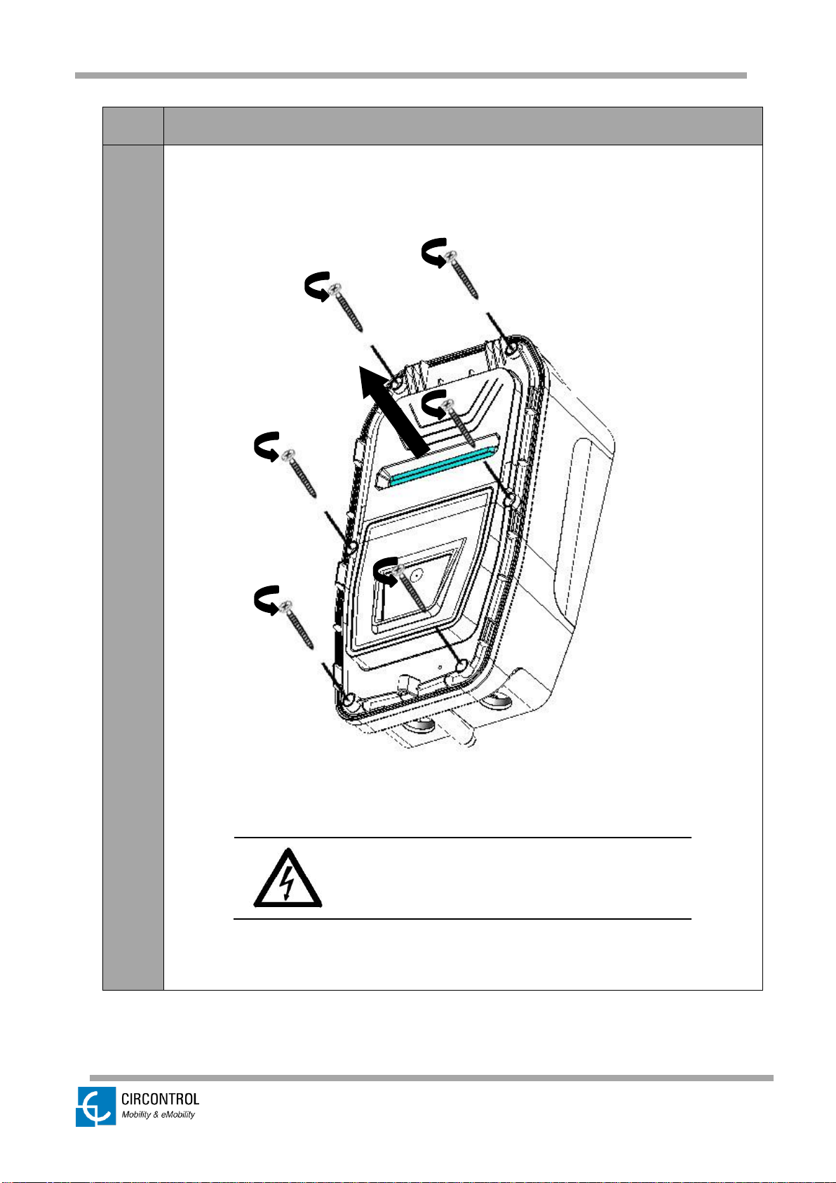
4.
Remove the six screws of the front part by using a screw driver and take out the front
part of the enclosure.
Be sure that the unit is not energised before
going forward with the opening procedure.

© CIRCONTROL
www.circontrol.com
Wallbox eHOME INSTRUCTION & INSTALLATION MANUAL
22
STEP
ACTION
5.
When the front part of the enclosure is off, you can access to the inside
components of the unit.
Only the authorised and qualified staff can
manipulate the electrical and electronic
components of the unit.

© CIRCONTROL
www.circontrol.com
Wallbox eHOME INSTRUCTION & INSTALLATION MANUAL
23
9.3 POWER SUPPLY LINE CABLE INSERTION
There are two possibilities to insert the electric wires or electric pipe:
a) Breaking out the cable insertion opening on the rear of the housing.
b) Using the cable insertion opening at the bottom of the housing.
In all cases it is required to install a cable gland to ensure properly installation and preserve
the IP of the unit.
Cable insertion opening on the rear of the housing
(breakable)
Cable insertion opening at the bottom of the housing

© CIRCONTROL
www.circontrol.com
Wallbox eHOME INSTRUCTION & INSTALLATION MANUAL
24
9.3.1 USING THE REAR CABLE INSERTION OPENING
Use a hammer and a flathead screwdriver carefully in order to break out the cable insertion
opening, as shown in the picture below.
Do not make any other holes on the enclosure. Use
only the marked cable insertion openings to install
the required electric pipes.
Install always double membrane seals to ensure IP
protection of the charging point.
Be careful of not damaging any of the inside
components when breaking out the rear cable
insertion opening.

© CIRCONTROL
www.circontrol.com
Wallbox eHOME INSTRUCTION & INSTALLATION MANUAL
25
9.3.2 USING THE BOTTOM CABLE INSERTION OPENING
Please follow these steps to use this opening:
- Introduce the cable through the opening and fix it properly by means of the supplied
M25 cable gland.
NOTE: The power supply cable must be 3x4mm2 (for the 16 A models) and 3x6mm2 (for
the 32 A models) to meet the supplied cable gland.
Do not make any other holes on the enclosure. Use
only the named cable insertion opening to install
the required electric pipes.
Install always either cable glands or double
membrane seals to ensure IP protection of the
charging point.
2
1

© CIRCONTROL
www.circontrol.com
Wallbox eHOME INSTRUCTION & INSTALLATION MANUAL
26
9.4 WALL FIXATION PROCEDURE
9.4.1 NEEDED MATERIAL
Below, it is shown the list of materials (not included) that are necessary to fix the unit on
the wall:
MATERIAL
Qty
PICTURE
DIMENSIONS
Wall plug
3
Ø 6mm
Screws
3
3x45mm
All materials shown in the above table may vary
depending on the wall surface type.
9.4.2 CONSIDERATIONS
• The unit is designed to drain the water properly from
the upper side down.
• The charging point must be installed vertically (use a
level tool to ensure its installation at an angle of 90º)
• Please ensure that the installation surface is flat.

© CIRCONTROL
www.circontrol.com
Wallbox eHOME INSTRUCTION & INSTALLATION MANUAL
27
9.4.3 INSTALLATION
STEP
ACTION
1.
Adjust the vertical position of the charging point to ensure the correct vision and
management for the end user.
Minimum recommended height: 600 mm
Please comply to your country specifications.
2.
1. Mark 3 holes taking into
account the picture
measurements (also
written on the rear face
of the box).
2. Place the enclosure on
a flat surface.
3. Use 3x45mm screws to
fix the unit to the wall.
4. Check whether the box
has any inclination using
a level tool.
238

© CIRCONTROL
www.circontrol.com
Wallbox eHOME INSTRUCTION & INSTALLATION MANUAL
28
3.
a) Use Ø 6 drill size to make the 3 holes into the wall.
b) Install the anchor according to the surface material.
4.
• Use a screw driver to fix the unit on the wall (recommended screw
dimensions: 3x45mm)
• Use only the unit holes indicated in the above picture to fix the unit on the
wall. Do not make any other holes on the housing; otherwise the water can
enter the unit when it rains.
All screws and wall plugs needed to attach
the unit to the wall are not included.
.
a
b
© CIRCONTROL
www.circontrol.com
Wallbox eHOME INSTRUCTION & INSTALLATION MANUAL
29
9.5 ELECTRICAL INSTALLATION
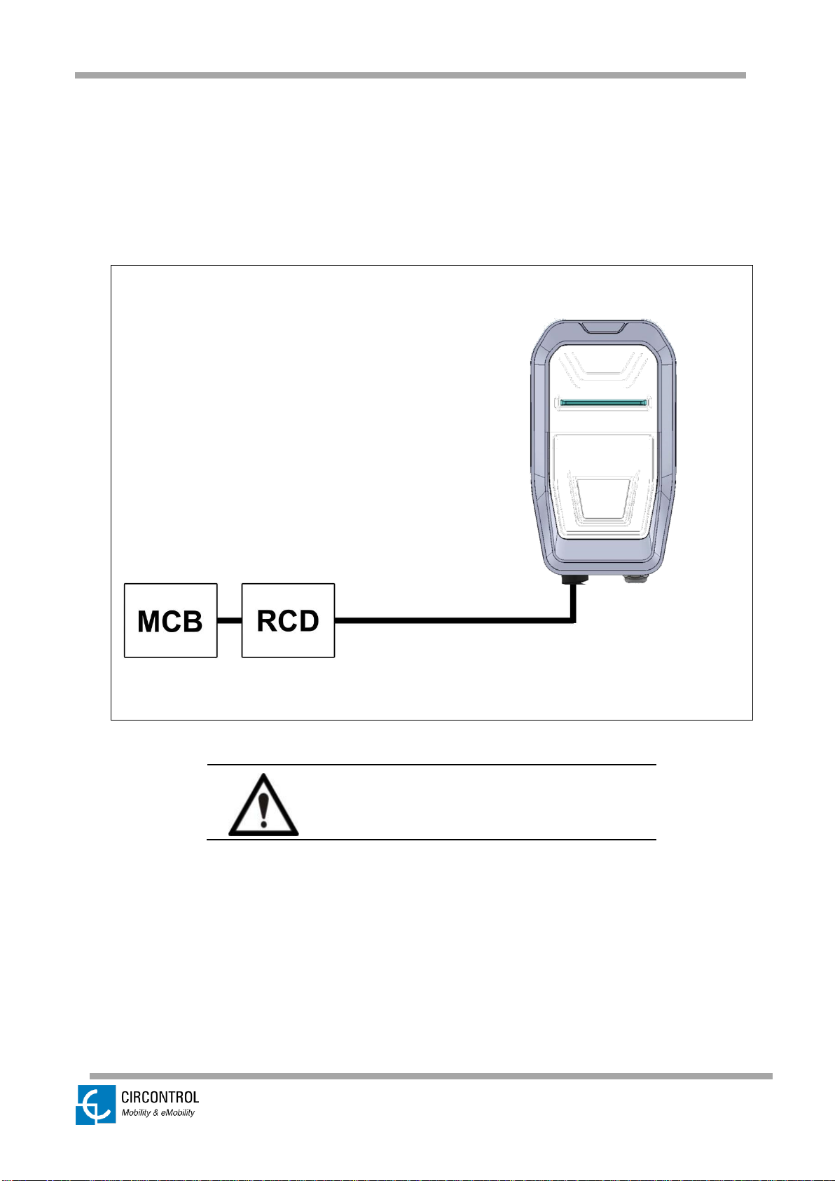
9.5.1 POWER SUPPLY LINE PROTECTIONS
On these series, the Wallbox eHOME doesn’t include electrical protections.
For protecting the power line, it is necessary to install a Miniature Circuit Breaker (MCB)
and a Residual Current Device (RCD) externally.
The charging point is set to 16A / 32A,
depending on the model, from factory
default settings.
© CIRCONTROL
www.circontrol.com
Wallbox eHOME INSTRUCTION & INSTALLATION MANUAL
30
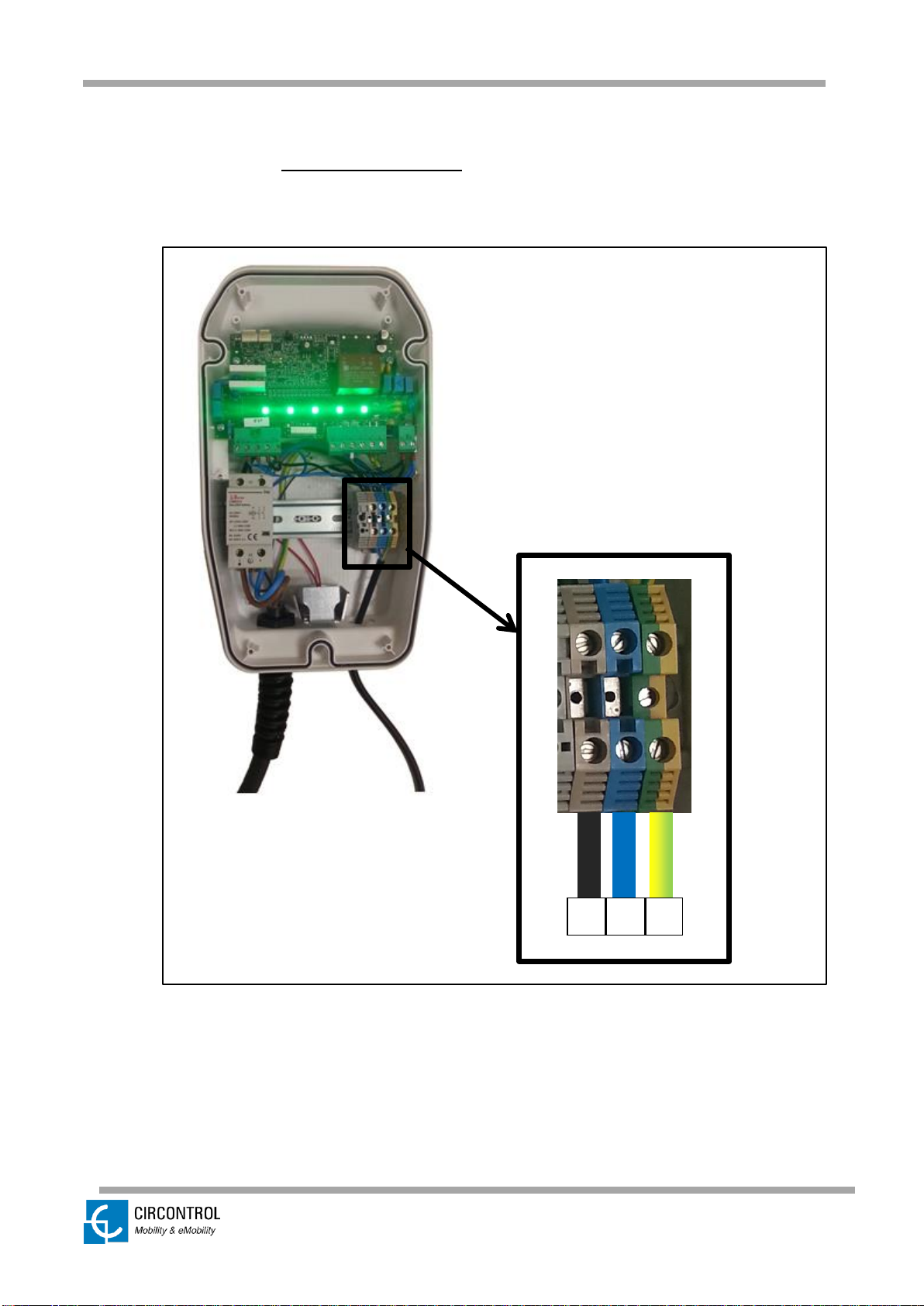
9.5.2 POWER SUPPLY LINE CONNECTION
- Perform the 230 VAC Single-phase connections as shown in the picture below.
- Do not forget to connect the ground cable (PE) to its corresponding terminal.
N P PE

© CIRCONTROL
www.circontrol.com
Wallbox eHOME INSTRUCTION & INSTALLATION MANUAL
31
9.6 CLOSING THE UNIT
STEP
ACTION
1.
Place back the 6 screws from the front cover in order to close the unit.
Beware of the cables between the cover and
the base while closing the unit.

© CIRCONTROL
www.circontrol.com
Wallbox eHOME INSTRUCTION & INSTALLATION MANUAL
32
STEP
ACTION
2.
Put the frame back, from the top to the bottom of the box, ensuring it does click at
the six points shown in the picture.
Be sure that the frame is properly adjusted to
the front cover in order to preserve the IP of
the unit.
CLICK!
CLICK!
CLICK!
CLICK!
CLICK!
CLICK!
1
2

© CIRCONTROL
www.circontrol.com
Wallbox eHOME INSTRUCTION & INSTALLATION MANUAL
33
10 CHECKING THE UNIT STATUS
Once all installation procedure has been performed, check the following points:
1. Check that the EV tethered cable and its connector are in proper conditions before
starting the charging operation.
2. Check that no abnormal noise appears while the unit is charging.
3. Check the status LED bar to know the present operating status of the unit. Below
you can see the table with the four possible LED bar operating colors:
PLUG STATE
LED BAR COLOR
Available
Green
Charging
Blue (flashing)
Charged
Blue
Fault
Red (flashing)
Heating
Orange
NOTE: For further information about the different status led bar sequences, please refer to
OPERATING INSTRUCTIONS section.
11 CURRENT LIMIT SELECTOR
As commented at the beginning of this document, there is an onboard rotative dipswitch to
configure the limit current of the unit, which has to be set up according to the model of
Wallbox eHOME we are going to install.
Be sure that the position of the current limit selector is
setup according to the output current of your unit.

© CIRCONTROL
www.circontrol.com
Wallbox eHOME INSTRUCTION & INSTALLATION MANUAL
34
On the following table is shown the different values available for this current limit selector:
POSITION
LIMIT CURRENT
0
NOT USED
1
6 A
2
10 A
3
13 A
4
16 A
5
20 A
6
32 A
7
NOT USED
8
NOT USED
9
NOT USED

© CIRCONTROL
www.circontrol.com
Wallbox eHOME INSTRUCTION & INSTALLATION MANUAL
35
12 REMOTE CONTROL INPUT
The Wallbox eHOME offer the possibility of enabling the charging process by connecting
an external free-of-potential contact to a dedicated on-board input (pins 4 & 5).
When the contact START is closed, if the EV is connected to the unit, it will start the
recharge straight away.
This remote control input is enabled by default, by means of a jumper (as shown in the
picture below). You must remove the jumper to use the input 4-5.
Be sure that the jumper is connected by default,
otherwise the charging process cannot start.

© CIRCONTROL
www.circontrol.com
Wallbox eHOME INSTRUCTION & INSTALLATION MANUAL
36
13 eHOME BeON (optional)
The eHOME BeON is an optional device that can optimize the Electric Vehicle (EV)
Charger. It is the responsible to analyze the total current consumption in the residential, and
to manage the remaining current for the EV Charger, avoiding any tripping the Main Circuit
Breaker (MCB) for overconsumption.
BeON product range: 16 A for 3,7* kW, 20 A for 4,6* kW, 25 A for 5,75* kW, 30 A for 6,9*
kW, 35 A for 8,05* kW, 40 A for 9,2* kW, 45 A for 10,35* kW, 50 A for 11,5* kW, 63 A for
14,49* kW.
*Values for Single-phase
The device eHOME BeON is connected downstream of the main power switch and
upstream of the main loads.
Only the authorised staff can manipulate the
electrical and electronic components.
• Comply strictly with electrical safety regulations according to your country.
• Do not make repairs or manipulations with the unit energised.
• Only trained and qualified personnel should have access to low-voltage electrical
parts inside the device.
• Remove from service any item that has a fault that could be dangerous for users
(broken plugs, caps that don’t close...).
• Use only Circontrol supplied spare parts.
•
• All the LEDs of the status LED
bar turns into blue flashing when
there is no enough current to charge
the EV, when there is enough
current, the system is reestablishing the charging process
automatically
LED BAR STATUS CONSIDERATION

© CIRCONTROL
www.circontrol.com
Wallbox eHOME INSTRUCTION & INSTALLATION MANUAL
37
13.1 CONNNECTIONS OF eHOME BeON
1. EV tethered cable
2. Output contactor
3. Main board
4. Current limit selector
5. Rear cover
6. RGB LEDs
7. Input terminals
8. Heater*
9. Power supply line
10. eHOME BeON
Negative / Pin 2S1
11. eHOME BeON
Positive / Pin 2S2
* Optional depending on the model

© CIRCONTROL
www.circontrol.com
Wallbox eHOME INSTRUCTION & INSTALLATION MANUAL
38
14 TECHNICAL DATA
Wallbox eHOME
AC INPUT
AC Power supply
1P + N + PE
AC Voltage
230VAC +/- 10%
Nominal input current
16 A / 32 A*
Nominal input power
3,7 kW / 7,4 kW*
Frequency
50 / 60 Hz
OUTPUT
Charge system
Mode 3
Sockets/ Plugs
Type 1 / Type 2 tethered cable*
Cable length
5m
Lock system
No
Maximum output power
3,7 kW / 7,4 kW*
Maximum output current
16 A / 32 A*
Output voltage range
230V
AC
(1P + N + PE)
GENERAL
Enclosure rating
IP54 / IK10
Enclosure material
ABS-PCV0
Operating temperature
-5ºC to +50ºC
Operating humidity
To 95% RH Non-condensing
Net weight
4Kg
OPTIONAL FEATURES
Extended operating temperature
(Optional Heater) -30ºC…+50ºC
eHOME BeON*
PRODUCT SPECIFICATION
Type Current Transformer
Ring Core
Material
Polyester
Dimensions
30 x 15 mm
Rated Insulation Level
0.72 / 3 /- kV
Connection
2S1 (-) / 2S2 (+)
Relation
16 / 0.05 A, 20 / 0.05 A, 25 / 0.05 A, 30 / 0.05 A, 35 / 0.05 A,
40 / 0.05 A, 45 / 0.05 A, 50 / 0.05 A, 63 / 0.05 A
Accuracy
Class I
Maximum cable length
200 m
Cable cross-section
1 mm²
* Depending on the model

© CIRCONTROL
www.circontrol.com
Wallbox eHOME INSTRUCTION & INSTALLATION MANUAL
39
15 NOTES

© CIRCONTROL
www.circontrol.com
Wallbox eHOME INSTRUCTION & INSTALLATION MANUAL
40

www.circontrol.com
 Loading...