

Page 1
3.0
Fuse Link Specifications:
These BET’s have a built in 26 gauge fuse link. If an
overcurrent condition were to occur, the chassis will act as a
fuse chamber, greatly reducing any threat to safety. Once
fuse links have been fused, they cannot be rehabilitated or
repaired.
4.0
Installation Data:
The Terminal should be installed to the network’s standard
installation procedure. However, the following factors should
be considered.
4.1 Use care when unpacking the Terminal from its shipping
carton to avoid damage to the Terminal, modules, or
connectors.
4.2 Install the Terminal as close to the incoming entrance cable as
possible.
4.3 The Terminal can be mounted on any level, uniform vertical
surface.
Install the Terminal where it will be accessible to technicians at
all times without the terminal obstructing individuals or
equipment.
Note: Although the Terminal is designed to withstand extreme
conditions, it is always best to avoid any unnecessary
problems by observing the following important notes: When
installing the Terminal, it is highly recommended that unit be
placed in a non-combustible area. (The environment
surrounding these devices should not contain flammable
materials such as curtains, carpeting, etc.)
If the installation for the telco equipment is not in an assigned
electrical room, it is advised to avoid areas with dust, moisture,
extreme environmental conditions, heavy traffic areas requiring
rolling machinery, pipes used to transport water, fuel, and
gases.
4.4 Avoid exposing the Terminal to chemicals or cleaning liquids,
which could damage various plastic components within the
device.
5.0
Installation Procedures:
Mount the Terminal to a surface using the supplied mounting
screws or approved network standards screws.
5.1
Outside Plant Termination (Incoming/66 Block):
To terminate the entrance quick-clip pairs to the incoming
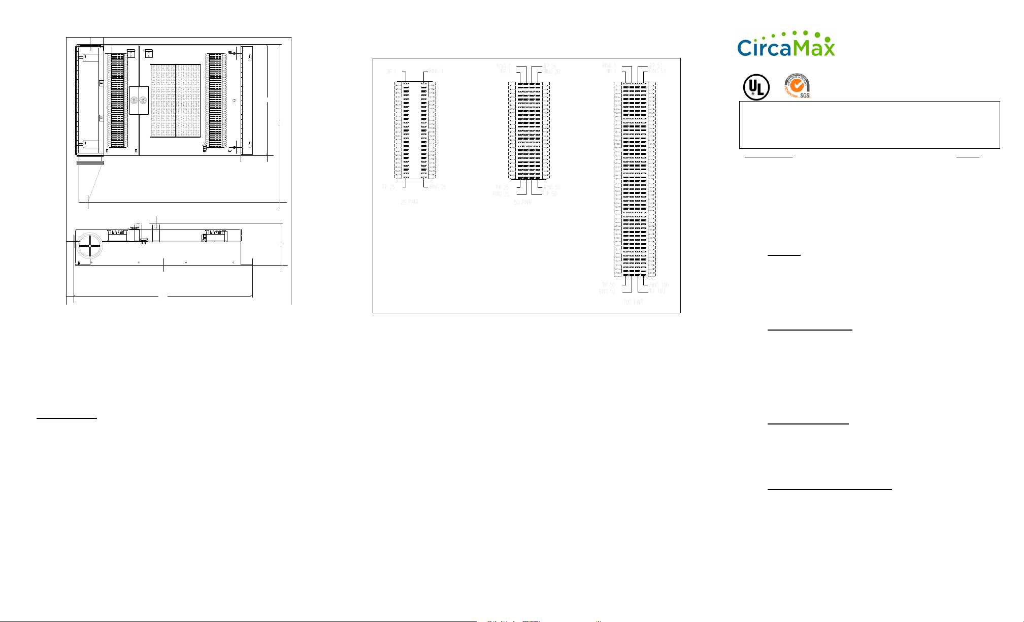
quick-clip block the procedure is as follows: Refer to Figure 1
for quick-clip terminal arrangements. The entrance quick-clip
pairs should be routed through the fanning strip of the
incoming portion of the quick-clip block. The pairs should then
be jumpered to the quick-clip terminals, using an industry
standard 714-termination tool.
Caution: Do not use a screwdriver for attaching line pairs to
quick-clip terminals, as a screwdriver may spread the clip
beams and result in a faulty connection
5.2
Distribution Termination (Outgoing/66 Block):
Refer to 5.1 Outside Plant Termination for outgoing/66 Block
termination.
6.0
Grounding:
The Terminal has two locations to attach a ground wire
(located on the side or top face of the Terminal). A #6 AWG
wire should be connected from one of the Terminal ground
lugs to a local ground as per network standard methods. It
should be noted that incorrect bonding, grounding or standards
would result in terminal and protection module failure.
7.0
Terminal Module Installation:
If the Terminal is purchased with the terminal modules
installed they will be inserted in the terminal panel in the detent
position. A distinctive “notch” in the three long pins of the
module indicates the detent position. This will connect the
incoming tip / ring as well as grounding circuits of the module.
Note: When the module is in detent position it will protect
only the incoming (outside plant) cable. The module must
be fully inserted to provide protection to both the central
office and customer premise side of the installation.
7.1 After all incoming and outgoing connections are completed;
fully insert the terminal module until the base of the module
meets the terminal block. This will connect the Distribution
Termination (Outgoing/66) side of the unit to the Outside Plant
(Incoming/66) side of the unit.
7.2 Fully test all connections.
8.0
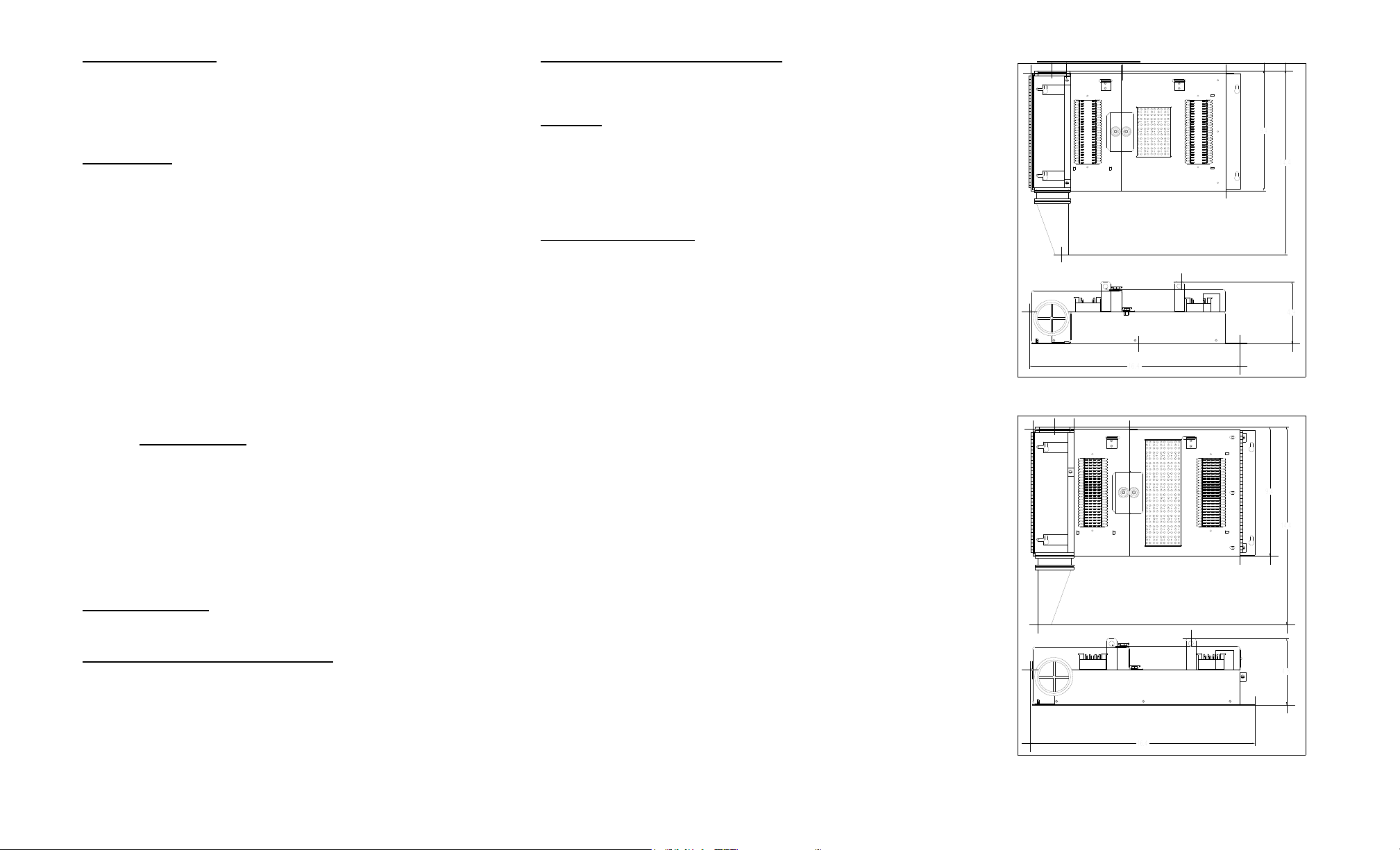
Terminal Diagrams:
1890ECT1-25
1890ECT1-50
Page 2
1890ECT1-100
1890ECT1 SERIES
INSTALLATION
PROCEDURE
(FOR INDOOR USE ONLY)
Building Entrance
Terminal
1890ECT1-25, 50, 100
CONTENTS:
PAGE
1.0
General
1
2.0
Terminal Module Specifications
1
3.0
Fuse Link Specifications
2
4.0
Installation Data
2
5.0
Installation Procedures
2-3
6.0
Grounding
3
7.0
Terminal Installation
3
8.0
Terminal Diagrams
4-5
1.0
General:
The 1890 Series Building Entrance Terminals are double
cross – connect field, indoor protection units designed for
terminating outside plant cables. The 1890 Series BET’s
are available in 25, 50, or 100 pair counts with a Quick Clip
block in / Quick Clip block out configuration.
1.1
Terminal Dimensions:
Model
Height
Width
Depth
1890ECT1-25
9.4in
16.4in
4.9in
1890ECT1-50
9.4in
16.4in
4.8in
1890ECT1-100
11.9in
18.9in
4.5in
1.2
Cable Requirements:
This BET is equipped with a 26 gauge fuse link; therefore it
must only be spliced with 24 gauge or physically larger
gauge C.O. feeder cable. This will ensure the highest
operating conditions for the BET.
2.0
Terminal Module Specifications:
The Terminal will accept any five-pin module of Western
Electric design.
To maintain UL Listing, only UL Listed Terminal
modules are to be used.
Figure 1- Incoming/Outgoing Quick Clip Blocks
Important Note:
All statements, technical information and recommendations related to the
Seller’s products are based on information believed to be reliable, but the
accuracy or completeness thereof is not guaranteed. Before utilizing the
product, the user should determine the suitability of the product for its intended
use. The user assumes all risks and liability whatsoever in connection with
such use. Any statements or recommendations of the Seller, which are not
contained in the Seller’s current publications, shall have no force or effect
unless contained in an agreement signed by an authorized officer of the Seller.
The statements contained herein are made in lieu of all warranties, express or
implied, including but not limited to the implied warranties of merchantability
and fitness for a particular purpose which warranties are hereby expressly
disclaimed.
Seller shall not be liable to the user or any person under any legal theory,
including but not limited to negligence or strict liability, for any injury or any
direct or consequential damages sustained or incurred by reason of the use of
any of the Seller’s product that were defective.
Terminal shall be installed to the applicable requirements of the:
National Electrical Code, ANSI/NFPA 70(Article 800, Section C)
Canadian Electrical Code, Part 1 (Section 60)
TM91-0055
REV.02
CAUTION: Risk of electric shock
Terminal is not be used without the arrester assembly installed.
 Loading...