

Page 1
RS51
Mobile Computer
(Android™ 6.0, Marshmallow)
Version 1.00
Page 2

Preface
PREFACE
COPYRIGHT
DISCLAIMER
TRADEMARK RECOGNITION
CONTACT
Copyright © 2017 CIPHERLAB CO., LTD.
All rights reserved
The information co ntained in this document, including all picture s, illustrations and software,
is the proprietary information of CIPHERLAB CO., LTD. and its respective legal owne rs; it is
protected by copyright laws and international copyr ight treaties, as well as other intellectual
property laws and treaties, with all rights reserved.
In no event and by no part shall this document be reproduced, stored in a retrieval system,
or transmitted in any form or by any means including but not limited to electronic,
mechanical, photocopying, and recording without the prior written consent of CIPHERLAB
CO., LTD. Any reverse engineering of software is also prohibited.
The information herein is subject to change without notice. The information and the
intellectu al property h erein are confi dential between you and CIPHERLAB C O., LTD. and
remain the ex clusive property o f CIPHERLAB CO., LTD. and its respecti ve legal owners.
Should you find any problems in this do cument, please report them to CIPHERL AB in writing.
CIPHERLAB does not warrant this document is error-free.
CipherLab logo is a registered tr ademark of CIPHERLAB CO., LTD. All other brands, products
and services, and trademark names are the property of their registered owners. The
editorial use of these names is for identification as well as to the benefit of the owners, with
no intention of infringement.
Google, Google Play, Android and other marks are trademarks of Google Inc.
For product consultancy and technical support, please contact CIPHERLAB’s sales
representative in your local area. You may also visit CIPHERLAB web site for more
information.
CIPHERLAB CO., LTD.
Website: http://www.CipherLab.com
- 2 -
Page 3

Important Notices
IMPORTANT NOTICES
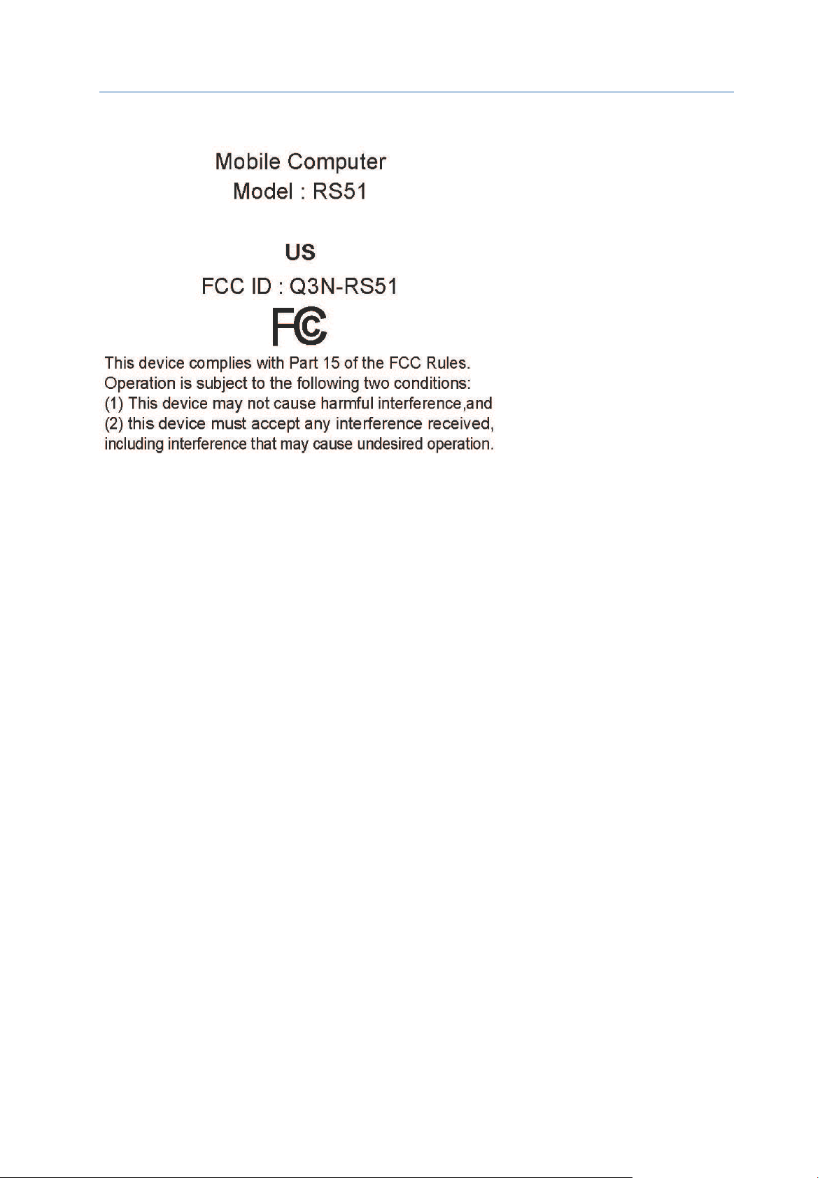
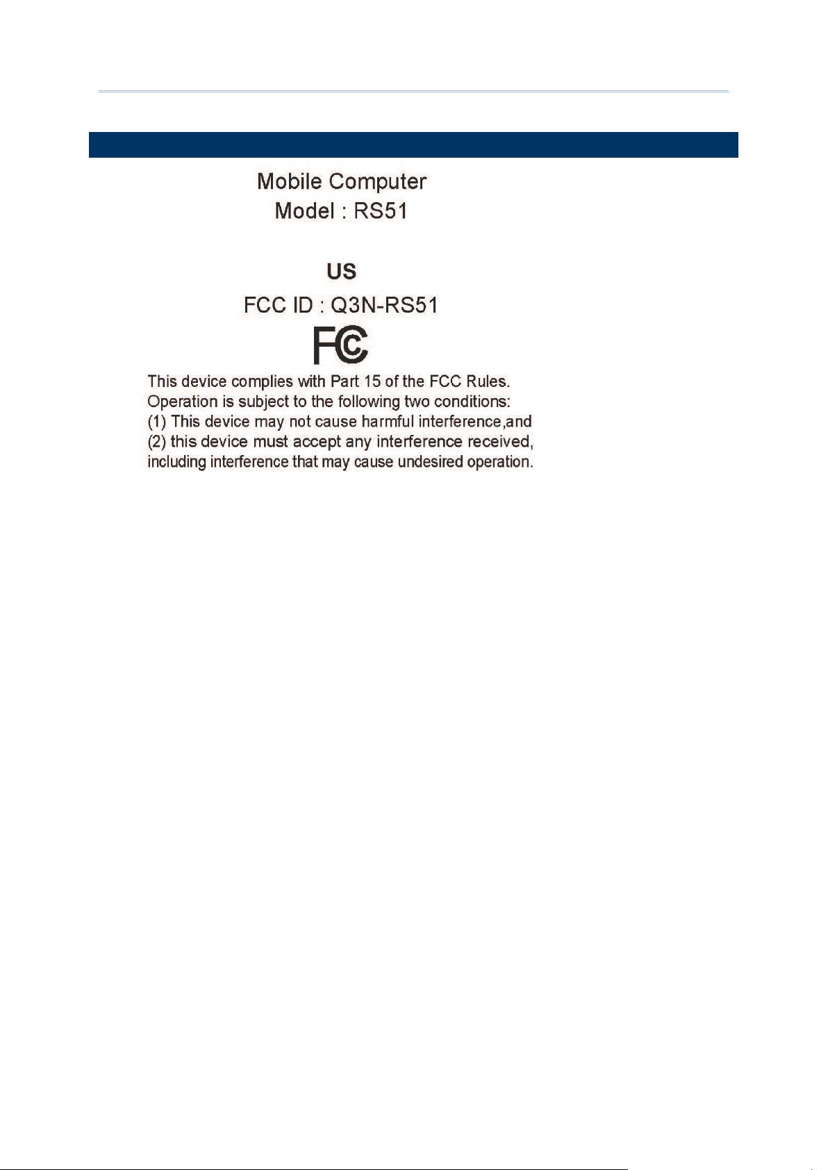
FOR USA
FCC ID : Q3N-RS51
This equipment has been tested and found to comply with the limits for a Class B digital
device, pursuant to Part 15 of the FCC Rules. These limits are designed to provide
reasonable protection against harmful interference in a residential installation. This
equipment generates, uses and can radiate radio frequency energy and, if not installed and
used in accordance with the instructions, may cause harmful interference to radio
communication. However, there is no guarantee that interference will not occur in a
particular installation. If this equipment does cause harmful interference to radio or
television reception, which can be determined by turning the e quipment off and on, the user
is encouraged to try to correct the interference by one or more of the following measures:
Reorient or relocate the receiving antenna.
Increase the separation between the equipment and receiver.
Connect the equipment into an outlet on a circuit different from that to which
the receiver is connected.
Consult the dealer or an experienced radio/TV technician for help.
This devi ce com pli es w ith Part 15 o f th e FC C R ul es. Op erat i on i s su bj ect to th e fol l owi ng
two conditions: (1) This device may not cause harmful interference, and (2) this device
must accept any interferenc e received, including interference that may cause und esired
operation.
FCC Caution:
Any changes or modifications not expressly approved by the party responsible for
compliance could void the user's authority to operate this equipment.
This transmitter must not be co-located or operating in conjunction with any other
antenna or transmitter.
Find the certificate information from :
- 3 -
Page 4
Important Notices
Setup About Phone Certificate
- 4 -
Page 5

Important Notices
FOR PRODUCT WITH LASER
This laser component emits FDA / IEC Class 2 laser light at
the exit port. Do NOT STARE INTO BEAM DIRECTLY.
Do not aim the beam at the eyes.
Any adjustments or performance excluding those specified may
result in hazardous laser light exposure.
ENVIRONMENT
and with humidity range from 10% to 90%.
humidity range from 5% to 95%.
conforms to protection class IP67.
Operate the ha nd y t erm in al at a mbi en t tem pera tu res f rom -20 °C t o 50 °C
Store the dev ice at ambient temperatures fro m -30 °C to 70 °C and with
Charge the device at ambient temperatures from 0°C to 35°C.
This device is built with a dust-proof and splash-proof structure that
SPECIFIC ABSORPTION RATE (SAR) INFORMATION
The product complies with the FCC po rtable RF exposure limit set forth for an uncontr olled
environment and are safe for intended operation as described in this manual. The further RF
exposure reduction can be achieved if the products can be kept as far as possible from the
user body or set the device to lower output power if such function is available.
Body-worn Operation
This device was tested for typical body-worn operations. To comply with RF exposure requirements, a
minimum separation distance of 10 mm must be maintained between the user’s body and the handset,
including the antenna. Third-party belt-clips, holsters, and similar accessories used by this device
should not contain any metallic components. Body-worn accessories that do not meet these
requirements may not comply with RF exposure requirements and should be avoided.
The SAR test distance is Head (0 mm), Body (10 mm) and Hotspot (10 mm).
FCC SAR Value (Standard limit is 1.6 W/Kg)
USA (1g): Max. 1.52 W/Kg
A minimum separation distance of 0.5 cm must b e maintained between the u ser’s body and the
device, including the antenna during body-worn operation to comply with the RF exposure
requirements in Europe.
To compliance w ith RF Exposure r equirements in Euro pe, third-party belt -clips, holsters or similar
accessories used by this de vice should no t contain any metallic components. The use of accessories
that do not satisfy these requirements may not comply with RF exposure requirements, and should be
avoided.
CE SAR Value (Standard limit is 2 W/Kg)
EU (10g): Max. 1.6 W/Kg
SAFETY PRECAUTIONS
- 5 -
Page 6

Important Notices
RISK OF EXPLOSION IF BATTERY IS REPLACED BY AN INCORRECT TYPE.
BATTERY
DISPOSE OF USED BATTERIES ACCORDING TO THE INSTRUCTIONS.
For people’s safety
Do not listen at high volume levels for long periods to prevent possible
hearing damage.
Do not operate this device while walking, cycling or car driving .
For the equipment
Do not use any batteries or charging devices which are not originally sold
Do not replace the battery with an incorrect type, to avoid the risk of heat
generation, fire, or explosion.
Do not disassemble, incinerate or short circuit the battery.
Do not touch the contact pins of the battery pack.
Do not expose the handy terminal or battery to any flammable sources.
Do not exp ose the handy termi nal to extreme tem peratures or soa k it in
water.
Do not use any pointed or sharp objects against the screen surface.
Do not use the styluses which are not supplied, to prevent possible scratches
to the touch screen.
Water residue on the touch screen may cause abnormal behaviors or the fall
of its sensitivity le vels.
On the surface of the terminal and the barcode reading window, the fog or
water drops caused by low temperatures may influence barcode reading.
Do not use blea ches o r cl eaners t o clea n th e devi ce. Use a clean , wet c loth
instead.
The main battery may not be charged to full for shipment. Charge the main
battery to full before using the handy terminal for the first time.
Main battery: The main battery powers the handy terminal to work. It takes
approximat ely 4 hours to charge a n empty main batt ery to full. The charging LED
above the scree n will light up in red w hile char ging and w ill tur n gre en when c harging
is complete.
When the mai n ba ttery i s remov ed, R TC ret enti on wil l be m aint ained for at
least 30 minutes.
Backup battery: The backup battery is mounted on the main board. Its role is
to temporarily keep the handy terminal in suspension when the main battery is drained
out so data in DRAM will be retained. The backup battery takes approximately 3.5
hours to charge to full by the main battery or power adapter.
It is recommended to charge the battery at room temperature (18°C to 25°C)
for optimal performance.
Battery charging stops when ambient temperature drops below 0°C or
exceeds 40°C.
In order to p revent syst em from shutting down after the battery is drained
out, keep a fresh battery for replacement at all t imes, or connect the handy terminal to
an external power.
If there are drippings or dust on the device or batter y pack, wipe them away
with a soft clean cloth before battery replace ment.
Turn off the power before battery replacement.
- 6 -
Page 7

Important Notices
If you want to put away the handy terminal for a period o f time, remove the
SCANNER
battery pack from the handy terminal’s battery compartment. Store the handy
terminal and battery pack separately.
Recycle batteries in a proper way for the green-environment issue.
Scan a 1D barcode
1) Open ReaderConfig and tap Scan Test on the menu bar.
2) Aim the scanning window at the barcode to read. Move the device,
having the barcode located in the center of the scanning area.
3) Press any of the two side triggers. The scanning light bea ms to read the
printed ba rcodes. The b uzz er beeps a fter scanning. The scanning light goes off once
the data is decoded, or when the decode timeout period has passe d.
Scan a 2D barcode
1) Open ReaderConfig and tap Scan Test on the menu bar.
2) Aim the scanning window at the barcode to read. Move the device,
having the barcode located in the center of the scanning area.
3) Press any of the two side triggers. The scanning light bea ms to read the
printed ba rcodes. The b uzz er beeps a fter scanning. The scanning light goes off once
the data is decoded, or when the decode timeout period has passe d.
- 7 -
Page 8

Important Notices
CONNECTION
CARE & MAINTENANCE
Via Bluetooth or WLAN
Connection may fail when the handy terminal is around other wireless
machines or power cables as the radio frequencies of those may cause interferences.
If communication fails, move the devices much closer to each other, and try
to communicate again
After turning on, Bluetooth power is s ustained even when the handy terminal
is suspended. H owever, if th e power mode is swi tched to Airpl ane Mode, Bluetooth
power will be turned off regardless of the settings.
Not Charging could be the result of battery damage, battery’s fa ilure to touch
the connector or AC plug coming off.
Charging error could be due to high battery temperature.
When the body of the handy terminal gets dirty, use a clean, wet cloth to
wipe off dust and debris. DO NOT use bleaches or cleaners.
Use a clean, non-abrasive, lint-free cloth to wipe dust off the LCD touch
screen. DO NOT use any pointed or sharp objects against the sur face. Always keep the
LCD dry.
If you want to put away the handy terminal for a period of time, download the
collected data to a host computer, and then remove the battery pack from the handy
terminal’s battery compartment. Store the handy terminal and battery pack
separately.
If you encounter malfunction o n the handy terminal, wr ite dow n the specific
scenario and consult your local sales representative.
- 8 -
Page 9
Important Notices
USA E-LABEL
- 9 -
Page 10

Release Notes
RELEASE NOTES
Version
Date
Notes
1.00a Mar 23, 2016 2nd release
1.00 Nov 10, 2016 Initial release
- 10 -
Page 11

CONTENTS
PREFACE ........................................................................................................................................ - 2 -
RELEASE NOTES ......................................................................................................................... - 10 -
CONTENTS ...................................................................................................................................... 11
INTRODUCTION ............................................................................................................................... 12
QUICK START .................................................................................................................................. 13
SPECIFICATIONS ............................................................................................................................. 26
Copyright ........................................................................................................................................ - 2 -
Disclaimer ...................................................................................................................................... - 2 -
Trademark Recognition ................................................................................................................. - 2 -
Contact ........................................................................................................................................... - 2 -
Inside the Package .......................................................................................................................... 12
Accessories ...................................................................................................................................... 12
Overview ........................................................................................................................................... 13
Installing Battery ........................................................................................................................ 15
Installing SIM Card, SAM Card and Memory Card .................................................................... 17
1.1.1. Power On/Off Mobile Computer ........................................................................... 18
1.1.2. Homescreen Selection .......................................................................................... 19
1.1.3. Using Hardware Buttons ....................................................................................... 20
1.1.4. Connecting Headset .............................................................................................. 20
1.2. Charging & Communication .................................................................................. 21
1.2.1. Charge Mobile Computer ...................................................................................... 21
1.2.2. Wired Data Transmission ...................................................................................... 25
Platform, Processor & Memory....................................................................................................... 26
Communication & Data Capture .................................................................................................... 27
Electrical Characteristics ................................................................................................................ 28
Physical Characteristics .................................................................................................................. 28
Environmental Characteristics ....................................................................................................... 29
Programming Support ..................................................................................................................... 30
11
Page 12

Introduction
INTRODUCTION
INSIDE THE PACKAGE
ACCESSORIES
The RS51 Mobile Computer, powered by Android™ 6.0, Marshmallow, is light-weight, easy
to use, and provides more powerful and handy tools.
Specifically designed to work as an industrial PDA, it provides rich options of data collection,
voice and data communication, long-lasting working hours, and so on. Its large color
transmissive display guarantees ea se in readi ng i n all ligh ting condi tions. Integra ted w ith
Bluetooth v4.1, v2.1+EDR and 802.11 a/b/g/n/ac technologies, the mobile computer al so
includes a GSM/UMTS/LTE module to gain greater speeds and optimal mobility. In
particular, an integrated GNSS (Global Navigation Satellite System) receiver is made
available for use with third-party location-based applications.
This manual serves to guide yo u thr o ugh ho w to inst a ll, co nfigure , and oper ate the mobile
computer. The Care & Maintenance section is specifically crucial for those who are in charge
of taking care of the mobile computer.
We recommend you to keep one copy of the manual at hand for quick reference or
maintenance purposes. To avoid any improper disposal or operation, please read the
manual thoroughly be fore use.
The following items are included in the kit package. Save the box and packaging material
for future use in case you need to store or ship the mobile computer.
RS51 Mobile Computer
Rechargeable Li-ion battery pack
Wrist Band
Snap-on USB Charging & Communication Cable
AC Power Adaptor
Quick Guide
Single Cradle with USB Communication
4-slot Battery Charger Cradle
Car Charger Cable
12
Page 13

Quick Start
Chapter 1
QUICK START
OVERVIEW
13
Page 14

Quick Start
No. Description No. Description
1 Status LED 2 Proximity+ALS Sensor
3 Phone Receiver 4 Power Button
5 Side Key 6 Microphone
7 Charging & Communication Pins 8 Touchscreen
9 Scan Window 10 Headset Jack
11 Volume Buttons 12 Loudspeaker
13 Wrist Band Hole 14 Battery Latch
15 NFC Detection Area 16 Battery (with Cover)
17 Camera Flash 18 Camera Lens
19 Rear Microphone
14
Page 15

Quick Start
INSTALLING BATTERY
IMPORTANT CHARGING INFORMATION
For shipping and storage purposes, the mobile computer and the main batter y are saved in
separate packages.
Note: Any improper handling may reduce the battery life.
To install the main battery:
1) Insert the main battery with the contact pins facing the lower end. Fix the lower edge of
the battery first.
2) Push the upper end in, the battery latch w ill click into place wit h a “click” sound
Power Supply
Battery Pack
(Optional)
Charging time
Input: AC 100-240V, 50-60Hz; output: 5V/2A
CipherLab approved
3.8V 4000mAH/3.8V 5300mAH (Standard/Extended)
rechargeable Li-ion CipherLab proprietary
Approx. 5 hours/6 hours (Standard/Extended battery) via
adapter
15
Page 16

Quick Start
REMOVE BATTERY
1) Press down the power key and tap “Power off” to shut down this device.
2) Slide the key latch Right, the battery will be unlocked with a “click” sound.
3) Lift the battery up from its upper end.
16
Page 17

Quick Start
INSTALLING SIM CARD, SAM CARD AND MEMORY CARD
REMOVE CARDS
The RS51 Mobile Computer is equipped with two SIM card slots, one SAM car d slot and one
memory card slot.
To insert the cards:
1) Remove the battery.
2) Inser you r fi ngernail in to the notch ab ove the inner lid that protects the card sockets
chamber and lift it up.
3) After the chamber is revealed, insert SIM cards, the SAM card and the microSD card into
their respective sockets. Close and push back the hinged cover till a “click” sounds.
4) Replace the inner lid.
5) Replace the battery.
1) Remove the battery.
2) Remove the inner lid.
3) Unlock the card hinge cover and remove the card.
4) Replace the inner lid and the battery.
17
Page 18

Quick Start
1.1.1. POWER ON/OFF MOBILE COMPUTER
POWER ON
錯誤! 找不到
參照來源。
When powering on this mobile computer, if you
Any system failure, data loss or unexpected consequences arising from your entering the
POWER OFF
To power on the mobile computer, press and hold the power button located on the
upper right side of the device. The mobile computer will turn on and show the
Note:
For the mobile computer to power on, the battery cover must be secured in place.
Warning:
accidentally enter a hidden advanced boot menu,
please use Volume Up key to select and Volume
Down key to confirm [Normal Boot] to return to
the normal booting process.
other two opti ons - [Recovery Mode] and [Factory Mode] is out of CIPHERLAB ’s
warranty coverage.
after splash screen.
To power off the mobile computer, press and hold the power button for more than three
seconds. A menu will appear on-screen which allows you to power off the device. Make sure
all user data and tasks have been stored before tapping on Power off.
18
Page 19

Quick Start
1.1.2. HOMESCREEN SELECTION
Upon the first time you launch the system, a Select Home app window will pop up to
request your i mm edi at e choi ce of h om e scr een . B y sel ect i ng “AppLock”, you will directly
enter AppLock application (please refer to AppLock User Guide for detailed instructions on
AppLock settings) to start configuring the inte rface provided to normal users of this de vice;
by selecting “Launcher”, you will enter the default Android™ 6.0 home screen.
19
Page 20

Quick Start
1.1.3. USING HARDWARE BUTTONS
Button
Function
Description
1.1.4. CONNECTING HEADSET
On the bottom of the mobile computer are three hardware
buttons that deliver the following functions:
Back button
Home button Displays the Home screen.
Recent apps
button
Returns to the prev ious screen or closes
the active window or keyboard.
Opens a list of recently used
applications.
The headset jack is located on the top of the mobile computer. You can use the headset for
audio playback or communication via the phone application, audio instant messa ging, etc.
1) Flip up the rubber cover.
2) Connect the headset to the headset jack.
3) Replace the rubber cover.
20
Page 21

Quick Start
1.2. CHARGING & COMMUNICATION
1.2.1. CHARGE MOBILE COMPUTER
CHARGING TIME
CHARGING TEMPERATURE
OPERATION ON BATTERY POWER
The main ba ttery may n ot be charg ed to fu ll for shi pmen t. When y ou first receive t he kit
package, you will need to charge the main battery to full before using the mobile computer.
You may use the Snap-on Charging Cable or Charging Cradle along with a power adapter to
charge the mobile computer.
Your device can be charged as well when connected to a computer via USB cable; however,
charging from a USB port on a computer is slower than charging using a supplied Snap-on
Charging Cable or Charging Cradle because the voltage and amperage the computer
provides is lower th an in the case of using a normal charging method.
Main battery: The main battery powers the mobile computer to work. It takes
approximately 4 hours to char ge an empty main batte ry to full. The charging LED above
the screen (located on the right) will light up in red while charging and will turn green
when charging is complete.
When the main battery is removed, RTC retention will be maintained for at least 30 minutes.
Backup battery: The backup battery is mounted on the main board. Its role is to temporarily
keep the mobile computer in suspension when the main battery is drained out so data in
DRAM will be retained. The backup battery takes approximately 3.5 hours to charge to full
by the main battery or power adapter.
It is recommended to charge the battery at room temperature (18°C to 25°C) for optimal
performance.
Please note t hat battery charging stops when ambient temperature drops below 0
exceeds 40°C.
°C or
When 802.11a/b/g/n, GSM/GPRS/EDGE/WCDMA/UMTS/HSDPA/HSUPA/HSPA+/LTE,
Bluetooth v4.1 & v2.1+EDR and GPS are all enabled on battery power, the main battery
level will drop down substantially. Prolonged use of the display and continued scanning of
barcodes will also affect battery level.
In order to prevent system from shutting do wn after the battery is drained out, we suggest
that you keep a fresh battery for replacement at all times, or connect the mobile computer
to an external power.
21
Page 22

Quick Start
USE SNAP-ON CHARGING CABLE
LED Indicator
Status
Description
LED Status Indic a tor
The Snap-on Charging Cable provides a co nvenient way to charge your mobile computer.
1) Fasten the Snap-on Charging Cable to the lower end of the mobile co mputer.
2) Connect the other end of the cable to the adapter.
3) Fix the adapter plug onto the adapter, and plug in into an elec trical outlet.
Click!
While the device battery is being charged, the LED on mobile computer will indicate
charging status.
Charging Red, solid Charging the mob ile computer
Red, blink Charging error
Green, solid Charging complete
No light Charging error ( c harging will stop)
Note:
The Snap-on Charging Cable is for charging only. For data communication, use the micro
USB cable to connect the mobile computer to your PC or laptop.
22
Page 23

Quick Start
USE CHARGING CRADLE
Cradle LED Indicator
Status
Description
The Charging Cradle charges your mobile computer and a spare battery at the same time.
Presents charging compartment for mobile computer and spare battery
Provides micro USB socket on the back for charging
Supports USB Host Mode via a USB OTG cable
Completes charging in approximately 5 hours
Two LEDs, one for power connection status and one for battery charging status
Adapter input 100-240V, AC, 50/60Hz; output 5V, DC, 2A.
Note:
The Charging Cradle is for charging only. For data communication, use the micro USB cable
to connect the mobile computer to your PC or laptop.
To charge your mobile computer on the Charging Cradle:
1) Insert the mobile computer o nto the Charging Cr adle. Press the mobile com puter down
till you hear a ‘click’ to make sure it is secured in the charging station. If the hardshell is
installed on the mobile computer, remove the cap on the Cradle’s charging station, and
insert the mobile computer.
2) Connect the adapter to the Cradle, and plug the other end into an electrical outlet.
The status of the mobile computer charging is shown on the device itself, while the LED
indicator on RS51 Charging Cradle shows the status of battery charging a s below:
Charging Red, solid Charging the battery
Red, blink Charging error
Green, solid Charging complete
No light Not charging
23
Page 24

Quick Start
Note:
(1) Not Charging could be the result of battery damage, battery’s failure to touch the
connector, or AC plug coming off.
(2) Charging error could be due to high battery temperature.
24
Page 25

Quick Start
1.2.2. WIRED DATA TRANSMISSION
Use the micro USB cable to connect the mobile computer to your PC for data transmission.
1) Connect your device to the computer with supplied USB cable.
2) Swipe down from the status bar to reveal Notifications Drawer.
3) Tap “USB for Charging” to enter USB options. By default, the device will be in charging
mode, in which you are unable to access the files on this device from the PC client. To
transfer al l types of files betw een your device an d PC, choose “File transfers”. To
transfer videos and photos, you can select “Photo transfer (PTP), in which your
device will share only videos and photos in DCIM and Pictures folders.
25
Page 26

Specifications
PLATFORM, PROCESSOR & MEMORY
Operating System & CPU
CPU
Cortex A53 Octa-core
Expansion Slot
One microSDHC c a rd slot (up to 32GB)
Micro SAM sock etx1
SPECIFICATIONS
OS Version Android™ 6.0 Marshmallow with GMS Certified
Memory
ROM 16GB eMMC
RAM 2GB
SDXC supported (up to 2TB)
Micro SIM socket x2
26
Page 27

Specifications
COMMUNICATION & DATA CAPTURE
Communication
USB Client USB 2.0 OTG
WPAN Bluetooth Class II, v4. 1 a nd v 2.1+EDR (2402~2480 MHz: 3.3dBm)
WLAN IEEE 802.11 a/b/g/n/ac networkin g
WWAN
GPS
(2412~2472 MHz: 18.41d Bm
5180~5240MHz: 21.06dBm,
5260~5320MHz: 21.46dBm,
5500~5700MHz: 21.90dBm,
5745~5825MHz: 14.30dBm(USA only))
Operations in the 5.15-5.35GHz band are restricted to indoor usage only.
Built-in WWAN modem for Quadband GSM, UMTS, LTE functions:
GSM/GPRS/EDGE/WCDMA/UMTS/HSDPA/H
Worldwide
Frequency bands:
GSM/GPRS/EDGE
880~915, 925~960MHz: 29dBm
1710~1785, 1805~1880MHz: 30dBm
WCDMA/UMTS/HSDPA/HSUPA:B1,B8
1922.4~1977, 2112.4~2167.6: 24dBm
880~915, 925~960: 24dBm
LTE: B1,B3,B7,B8,B20,B28,B38,B40
1922.4~1977, 2112.4~2167.6MHz: 23dBm
1710~1785, 1805~1880MHz: 23dBm
2500~2570, 2620~2690MHz: 23dBm
880~915, 925~960MHz: 23dB m
832~862, 791~821MHz: 23dB m
718~748, 758~773MHz: 23dBm
2570~2620MHz: 23dBm
2300~2399.9MHz: 23dBm
Americas
GSM : 850/1900
UMTS : B2,B4,B5
CDMA : BC0, BC1,BC10
LTE : B2,B4,B5,B7,B12,B13,B1
BDS(1561.098MHz),Galileo/GPS (1575.42MHz),GLONASS(1602.000MHz)
7,B25,B26
SUPA/HSPA+/LTE
,B38, B41
Data & Image Capture
Digital Camera Rear: 8 Mega pixels with user-controllable flash
Barcode Reader
HF RFID(13.56MHz)
Reader
2D CCD Imager
SE-4750 )
ISO14443A/B (Mifar e) , ISO15693 (Felica)
Supports NFC (Peer-to-peer, Card reader, Card emulation)
(Zebra
27
Page 28

Specifications
ELECTRICAL CHARACTERISTICS
Batteries
to 35°C. To
or exceeds 40°C, and resume charging after its
Power Adaptor
Working Time
PHYSICAL CHARACTERISTICS
Color Touch Screen Display
optically bonded to
Notifications
Integrated with one speaker, dual array digital microphones with
Dimensions & Weight
Main Battery Pack Rechargeable Li-ion battery: 3.8V, 5300mAh
Charging temperature: 0-35°C
Minimum char g ing time: 5 hours
Please Charge batteries in temperatures from 0°C
ensure that the battery is being ch arged under a safe condition, the
battery may disable charging when ambient temperature drops
below 0°C
temperature falls within the acceptable range.
Backup Battery Rechargeable Li-ion battery: 3.7V, 60 mAh
Data retention f or 3 0 m inutes
Charging time: 4 hours
Power Supply C or d with
Universal Power Adaptor
Supports working time for at least 10 hours at 25 degrees
Input AC 100~240 V, 50/60 Hz
Output DC 5V, 2A
@25°C
Display 4.66”, 16.7M color, HD (outdoor viewable,
Touch Panel), Asahi Dragontrail
Resolution HD (720x 1280 pixels)
Status LED 2 LEDs: one Tri-color LED + one Bi-color LED
Audio
echo and noise cancellation, HD voice support
Dimensions 163 mm (L) x 78mm (W) x 19mm (H)
Weight Under 360 g (2D Reader, in cluding battery)
28
Page 29

Specifications
ENVIRONMENTAL CHARACTERISTICS
Temperature
Humidity
Resistance
Operating -20°C to 50°C
Storage -30°C to 70 °C
Charging 0°C to 35°C
Operating 5% to 85% (non-condensing)
Impact Resistance Multiple drops onto concrete at 1.5 m on all six sides
Tumble Test 1000 times at 1m per applicable IEC tumble specification s
Electrostatic D ischarge ±15 kV air discharge, ±8 kV contact discharge
29
Page 30

Specifications
PROGRAMMING SUPPORT
Development Environment & Tools
Software & Utilities
ADC Client
JAVA Environment Android studio
Software Development Kit: JAR
C# Environment: Visual Studio
Software Development Kit: DLL (Xa m arin Library)
Software Package Reader Configuration
Software Trigger Key
Programmable Keys
WMDS Server
HF RFOD Config
App Lock
30
Page 31

CE Declaration of Conformity
For the following equipment:
Mobile Computer
(Product Name)
RS51
(Model Designation)
is herewith confirmed to comply with the requirements set out in the Council Directive on
the Approximation of the Laws of the Member States relating to Electromagnetic
Compatibility of Radio Equipment Directive (2014/53/EU). For the evaluation regarding the
Directives, the following standards were applied:
EN 300 328 V2.1.1 EN 300330 V2.1.1
EN 301 511 V12.5.1 EN 50566:2013 AC:2014
EN 301 908-2 V11.1.2 EN 303 413 V1.1.1
EN 301 908-13 V11.1.2 EN 301 908-1 V11.1.1
EN 50360 :2001 A1:2012 EN 62479:2010
EN 55024 : 2010 +A1:2015 EN 61000-3-2 :2014
EN 55032: 2015+AC:2016 EN 61000-3-3 :2013
EN 60950-1:2006+A2:2013 EN 301 893 V2.1.1
EN301 489-1 V2.1.1 Draft EN301 489-52 V1.1.0
Final draft EN301 489-3 V2.1.1 Draft EN 301 489-19 V2.1.0
EN301 489-17 V3.1.1
The following importer/manufacturer is responsible for this declaration:
CIPHERLAB CO.
(Company Name, Importer) (Company Name, Manufacturer)
12F, 333 Dunhua S. Rd., Sec.2, Taipei,
Taiwan R.O.C
(Company Address, Importer) (Company Address, Manufacturer)
Person responsible for this declaration: Person responsible for this declaration:
Herbie Jiang
(Name, Surname, Importer) (Name, Surname, Manufacturer)
Manager
(Position/Title) (Position/Title)
(Legal Signature) (Legal Signature)
Taiwan 2017/6/13
(Place) (Date) (Place) (Date)
Page 32

Object of the declaration:
I the undersigned, hereby declare that the equipment specified above conforms to the
above Directive(s) and Standard(s).
The Notified Body Telefication B.V., with Notified Body number 0560
performed: choose applicable Modules: B+C
Where applicable:
The issued EU-type examination certificate: note certificate number
 Loading...