

Page 1

Windows Embedded Handheld 6.5
CP55 Mobile Computer
Version 1.00
(WEH)
Page 2

PREFACE
COPYRIGHT
Copyright © 2014 CIPHERLAB CO., LTD.
All rights reserved
The information contained in this document, including all pictures, illustrations and software,
is the proprietary information of CIPHERLAB CO., LTD. and its respective legal owners; it is
protected by copyright laws and international copyright treaties, as well as other intellectual
property laws and treaties, with all rights reserved.
In no event and by no part shall this document be reproduced, stored in a retrieval system,
or transmitted in any form or by any means including but not limited to electronic,
mechanical, photocopying, and recording without the prior written consent of CIPHERLAB
CO., LTD. Any reverse engineering of software is also prohibited.
DISCLAIMER
The information herein is subject to change without notice. The information and the
intellectual property herein are confidential between you and CIPHERLAB CO., LTD. and
remain the exclusive property of CIPHERLAB CO., LTD. and its respective legal owners.
Should you find any problems in this document, please report them to CIPHERLAB in writing.
CIPHERLAB does not warrant this document is error-free.
TRADEMARK RECOGNITION
CipherLab logo is a registered trademark of CIPHERLAB CO., LTD. Windows Embedded
Handheld is a registered trademark or trademark of Microsoft Corporation in the United
States and/or other countries. All other brands, products and services, and trademark
names are the property of their registered owners. The editorial use of these names is for
identification as well as to the benefit of the owners, with no intention of infringement.
CONTACT
For product consultancy and technical support, please contact CIPHERLAB’s sales
representative in your local area. You may also visit CIPHERLAB web site for more
information.
CIPHERLAB CO., LTD.
Website:
http://www.CipherLab.com
Page 3

SAFETY NOTICES
FOR HAND-HELD PRODUCT WITH RF FUNCTIONS
CP55/CP55 G serial handheld equipment uses wireless radios that have been designed and
manufactured to meet safety requirements for limiting exposure to radio waves. When used
in accordance with the instructions set forth in this manual, the equipment has been
independently verified to not exceed the emission limits for safe exposure to radio
frequency (RF) energy as specified by EN50360 of EEC.
These limits are part of comprehensive guidelines and establish permitted levels of RF
energy for the general population. The guidelines are based on standards that were
developed by independent scientific organization through periodic and thorough evaluation
of scientific studies. The standards include a substantial safety margin designed to assure
the safety of all persons, regardless of age and health.
The exposure standard for all wireless devices employs a unit of measurement known as the
Specific Absorption Rate, or SAR; the SAR limit set by CE is 2.0W/Kg.
For trunk, the SAR value of CP55/CP55 G serial handheld is:
EEC: MAX 0.335W/Kg (CP55 G), 0.013 (CP55)
Page 4

FOR UNITED STATES
THESE PRODUCT MODELS HAVE BEEN CERTIFIED IN COMPLIANCE WITH THE
GOVERNMENT’S REQUIREMENTS FOR EXPOSURE TO RADIO WAVES.
The CP55 series mobile computer has been designed to comply with applicable safety
requirements for exposure to radio waves. Your mobile computer is a radio transmitter and
receiver. It is designed to not exceed the limits* of exposure to radio frequency (RF) energy
set by governmental authorities. These limits establish permitted levels of RF energy for the
general population. The guidelines are based on standards that were developed by
international scientific organizations through periodic and thorough evaluation of scientific
studies. The standards include a safety margin designed to assure the safety of all
individuals, regardless of age and health.
The radio wave exposure guidelines employ a unit of measurement known as the Specific
Absorption Rate (SAR). Tests for SAR are conducted using standardized methods with the
product transmitting at its highest certified power level in all used frequency bands. While
there may be differences between the SAR levels of various product models, they are all
designed to meet the relevant guidelines for exposure to radio waves.
The highest reported SAR values for body-worn accessory and simultaneous transmission
are 0.76W/kg, and 1.27W/kg respectively for CP55G. The highest reported SAR values for
body-worn operation are 1.03W/Kg for CP55. For body-worn operation, the product has
been tested when positioned a minimum of 15 mm from the body without any metal parts
in the vicinity of the product.
Before a WWAN model is available for sale to the public in the US, it must be tested and
certified by the Federal Communications Commission (FCC) that it does not exceed the limit
established by the government-adopted requirement for safe exposure*. The tests are
performed in positions and locations (i.e., by the ear and worn on the body) as required by
the FCC for each model. The FCC has granted an Equipment Authorization for this phone
model with all reported SAR levels evaluated as in compliance with the FCC RF exposure
guidelines. While there may be differences between the SAR levels of various phones, all
mobile phones granted an FCC equipment authorization meet the government requirement
for safe exposure. SAR information on this phone model is on file at the FCC and can be
found under the Display Grant section of
FCC ID Q3N-CP55G. Additional information on SAR can be found on the Cellular
Telecommunications & Internet Association (CTIA) website at
* In the United States and Canada, the SAR limit for mobile phones used by the public is 1.6
watts/kilogram (W/kg) averaged over one gram of tissue. The standard incorporates a
margin of safety to give additional protection for the public and to account for any
variations in measurements.
http://www.fcc.gov/oet/fccid after searching on
http://www.phonefacts.net.
Page 5

FOR PRODUCT WITH LASER
CAUTION
This laser component emits FDA / IEC Class 2 laser light at the exit port. Do not
stare into beam.
SAFETY PRECAUTIONS
RISK OF EXPLOSION: IF BATTERY IS REPLACED BY AN INCORRECT TYPE.
DISPOSE OF USED BATTERIES ACCORDING TO THE INSTRUCTIONS.
The use of any batteries or charging devices which are not originally sold or
manufactured by CipherLab will void your warranty and may cause damage to human
body or the product itself.
DO NOT disassemble, incinerate or short circuit the battery.
DO NOT expose the scanner or the battery to any flammable sources.
For green-environment issue, it's important that batteries should be recycled in a proper
way.
Under no circumstances, internal components are self-serviceable.
The charging and communication cradle uses an AC power adapter. A socket outlet shall
be installed near the equipment and shall be easily accessible. Make sure there is stable
power supply for the mobile computer or its peripherals to operate properly.
CARE & MAINTENANCE
This mobile computer is intended for industrial use. The mobile computer is rated IP65,
however, the mobile computer can get damaged when being exposed to extreme
temperatures or soaked wet.
When the enclosure of the mobile computer gets dirty, use a clean and wet cloth to wipe
off the dust. DO NOT use/mix any bleach or cleaner. Always keep the LCD dry.
For a liquid crystal display (LCD) or touchscreen, use a clean, non-abrasive, lint-free
cloth to wipe dust off the screen. DO NOT contact the surface with any pointed or sharp
object.
If you want to put away the mobile computer for a period of time, download the
collected data to a host computer, and then take out the battery pack. Store the mobile
computer and battery pack separately.
When the mobile computer resumes its work, it takes some time for the main and
backup batteries to become fully charged.
If you shall find the mobile computer malfunctioning, write down the specific scenario
and consult the sales representative in your local area.
Keep the mobile computer away from any magnets and magnetic fields to prevent the
laser engine from malfunctioning.
Page 6

EUROPE – EU DECLARATION OF CONFORMITY
This device complies with the essential requirements of the R&TTE Directive 1999/5/EC.
The following test methods have been applied in order to prove presumption of conformity
with the essential requirements of the R&TTE Directive 1999/5/EC:
EN 60950-1: 2001
EN 60950-1/A1: 2010
EN 60950-1/A11: 2009
EN 60950-1/A12: 2011
Safety of Information Technology Equipment
EN 62479:2010
Assessment of the compliance of low power electronic and electrical equipment with the
basic restrictions related to human exposure to electromagnetic fields (10 MHz to 300
GHz)
EN 62311: 2008 / Article 3(1)(a) and Article 2 2006/95/EC)
Assessment of electronic and electrical equipment related to human exposure
restrictions for electromagnetic fields (0 Hz-300 GHz) (IEC 62311:2007 (Modified))
EN 50360: 2001+A1: 2012
Product standard to demonstrate the compliance of mobile phones with the basic
restrictions related to human exposure to electromagnetic fields (300 MHz - 3 GHz)
EN 62209-1: 2006
Human exposure to radio frequency fields from hand-held and body-mounted wireless
communication devices – Human models, instrumentation, and procedures –
Part 1: Procedure to determine the specific absorption rate (SAR) for hand-held devices
used in close 13 proximity to the ear (frequency range of 300 MHz to 3 GHz).
EN 62209-2: 2010
Human exposure to radio frequency fields from handheld and bodymounted wireless
communication devices — Human models, instrumentation, and procedures
EN 300 330-2 V1.5.1: 2006
Electromagnetic compatibility and Radio spectrum Matters (ERM); Short Range Devices
(SRD); Radio equipment in the frequency range 9 kHz to 25 MHz and inductive loop
systems in the frequency range 9 kHz to 30 MHz; Part 1: Technical characteristics and
test methods.
EN 300 330-1 V1.7.1: 2010
Electromagnetic compatibility and Radio spectrum Matters (ERM); Short Range Devices
(SRD); Radio equipment in the frequency range 9 kHz to 25 MHz and inductive loop
systems in the frequency range 9 kHz to 30 MHz; Part 1: Technical characteristics and
test methods.
EN 300 440-1 V1.6.1: 2010
Electromagnetic compatibility and Radio spectrum Matters (ERM); Short range devices;
Radio equipment to be used in the 1 GHz to 40 GHz frequency range; Part1: Technical
characteristics and test methods.
Page 7

EN 300 440-2 V1.4.1: 2010
Electromagnetic compatibility and Radio spectrum Matters (ERM); Short range devices;
Radio equipment to be used in the 1 GHz to 40 GHz frequency range; Part 2:
Harmonized EN under article 3.2 of the R&TTE Directive.
EN 300 328 V1.7.1: 2006
Electromagnetic compatibility and Radio spectrum Matters (ERM); Wideband
Transmission systems; Data transmission equipment operating in the 2,4 GHz ISM band
and using spread spectrum modulation techniques; Harmonized EN covering essential
requirements under article 3.2 of the R&TTE Directive.
EN 301 893 V1.6.1: 2011
Broadband Radio Access Networks (BRAN); 5 GHz high performance RLAN; Harmonized
EN covering essential requirements of article 3.2 of the R&TTE Directive.
EN 301 908-1 V5.2.1: 2011
Electromagnetic compatibility and Radio spectrum Matters (ERM); Base Stations (BS),
Repeaters and User Equipment (UE) for IMT-2000 Third-Generation cellular networks;
Part 1: Harmonized EN for IMT-2000, introduction and common requirements, covering
essential requirements of article 3.2 of the R&TTE Directive.
EN 301 511 V9.0.2: 2003
Global System for Mobile communications (GSM); Harmonized standard for mobile
stations in the GSM 900 and DCS 1800 bands covering essential requirements under
article 3.2 of the R&TTE directive (1999/5/EC).
EN 301 489-1 V1.9.2: 2008
Electromagnetic compatibility and Radio Spectrum Matters (ERM); ElectroMagnetic
Compatibility (EMC) standard for radio equipment and services; Part 1: Common
technical requirements.
EN 301 489-3 V1.4.1 2002
Electromagnetic compatibility and Radio Spectrum Matters (ERM); ElectroMagnetic
Compatibility (EMC) standard for radio equipment and services; Part 3: Specific
conditions for Short-Range Devices (SRD) operating on frequencies between 9 kHz and
40 GHz.
EN 301 489-7 V1.3.1: 2005
ElectroMagnetic compatibility and Radio spectrum Matters (ERM); ElectroMagnetic
Compatibility (EMC) standard for radio equipment ad services; Part 7: Specific
conditions for mobile and portable radio and ancillary equipment of digital cellular radio
telecommunications systems (GSM and DCS).
EN 301 489-17 V2.2.1: 2012
Electromagnetic compatibility and Radio spectrum Matters (ERM); ElectroMagnetic
Compatibility (EMC) standard for radio equipment and services; Part 17: Specific
conditions for 2,4 GHz wideband transmission systems and 5 GHz high performance
RLAN equipment.
EN 301 489-24 V1.5.1: 2010
Electromagnetic compatibility and Radio Spectrum Matters (ERM); ElectroMagnetic
Compatibility (EMC) standard for radio equipment and services; Part 24: Specific
conditions for IMT-2000 CDMA Direct Spread (UTRA) for Mobile and portable (UE) radio
and ancillary equipment.
Page 8
0700
Page 9

DECLARATION OF CONFORMITY
Page 10

RELEASE NOTES
Version Date Notes
1.00 Nov 7, 2014 Initial release
Page 11

CONTENTS
PREFACE ...............................................................................................- 2 -
Copyright............................................................................................- 2 -
Disclaimer...........................................................................................- 2 -
Trademark Recognition...........................................................................- 2 -
Contact..............................................................................................- 2 -
Safety Notices......................................................................................- 3 -
For Hand-held Product with RF Functions .................................................- 3 -
For United States...............................................................................- 4 -
For Product with Laser........................................................................ - 5 -
Safety Precautions.................................................................................- 5 -
Care & Maintenance............................................................................... - 5 -
Europe – EU Declaration of Conformity ........................................................- 6 -
Declaration of Conformity .......................................................................- 9 -
RELEASE NOTES..................................................................................... - 10 -
INTRODUCTION........................................................................................... 1
About This Document .................................................................................1
Features.................................................................................................2
Inside This Package....................................................................................2
Accessories .............................................................................................2
USE MOBILE COMPUTER................................................................................ 3
1.1. Take a Tour ...........................................................................4
1.1.1. Overview ..............................................................................4
1.1.2. Inside Battery Chamber.............................................................5
1.1.3. Before Initial Use ....................................................................5
1.2. Power On/Off Mobile Computer...................................................6
1.3. Notifications ..........................................................................7
1.4. Battery.................................................................................8
1.4.1. Main Battery Setup ..................................................................8
1.4.2. Charge Batteries ................................................................... 10
1.4.3. Monitor Battery Level ............................................................. 13
1.4.4. Power Management................................................................ 17
1.5. Keypad............................................................................... 18
1.5.1. Physical keypad .................................................................... 18
1.5.2. On-screen Keyboard ............................................................... 23
1.5.3. Edit Text ............................................................................ 28
1.6. Touch Control ...................................................................... 29
1.6.1. Use Touchscreen ................................................................... 29
1.6.2. Screen Orientation................................................................. 29
1.6.3. Adjust Backlight.................................................................... 31
1.6.4. Calibration .......................................................................... 33
1.7. Memory .............................................................................. 34
1.7.1. Data Loss Caution.................................................................. 34
Page 12

1.7.2. Check Storage ...................................................................... 34
1.7.3. Insert SD Card ...................................................................... 36
1.8. Direct Data Communication...................................................... 37
1.8.1. Use Snap-on Cable ................................................................. 37
1.8.2. Use Cradle........................................................................... 38
1.8.3. Syncing Tools ....................................................................... 39
1.8.4. Sync Partnership ................................................................... 39
1.8.5. 1st USB Sync ......................................................................... 40
1.8.6. Disconnect USB ActiveSync....................................................... 41
1.8.7. ActiveSync Actions to Take....................................................... 42
1.9. Volume and Audio.................................................................. 47
1.9.1. Audio Playback ..................................................................... 47
1.9.2. Volume Control..................................................................... 47
DATA CAPTURE .........................................................................................49
2.1. Use Reader Config ................................................................. 50
2.1.1. Launch Reader Config............................................................. 50
2.1.2. General Settings.................................................................... 51
2.1.3. Symbology........................................................................... 58
2.1.4. Miscellaneous....................................................................... 62
2.1.5. Reader Config Option Menu ...................................................... 63
2.1.6. Read Printed Barcodes............................................................ 68
2.2. Use HF RFID Configuration........................................................ 70
2.2.1. Launch HF RFID Configuration ................................................... 70
2.2.2. General Settings.................................................................... 71
2.2.3. HF RFIDConfig Option Menu .................................................76
2.2.4. Read and Write RFID Tags ...................................................81
CAMERA ..................................................................................................85
3.1. Launch Camera..................................................................... 86
3.1.1. Camera Screen ..................................................................... 86
3.2. Take Pictures ....................................................................... 87
3.2.1. Camera Settings.................................................................... 88
3.3. Launch Video Camera ............................................................. 90
3.3.1. Video Camera Screen.............................................................. 90
3.4. Shoot Videos ........................................................................ 91
3.4.1. Video Camera Settings ............................................................ 92
3.5. View Pictures ....................................................................... 93
OPERATING SYSTEM....................................................................................95
4.1. 1st Startup........................................................................... 96
4.2. Today Screen ....................................................................... 97
4.2.1. Customize Today Screen.......................................................... 98
4.2.2. Return to Today Screen........................................................... 98
4.3. Start Screen......................................................................... 99
4.3.1. Return to Start Screen ...........................................................100
4.3.2. Title Bar ............................................................................100
4.3.3. Manage Notofications ............................................................102
4.3.4. Customize Start Screen ..........................................................104
4.3.5. Start Screen Icons.................................................................107
Page 13

4.4. Set Screen Lock ...................................................................109
4.4.1. Unlock Screen .....................................................................109
4.5. Manage Applications..............................................................110
4.5.1. Task Manager ......................................................................110
4.6. Suspend & Reset Mobile Computer.............................................116
4.6.1. Suspend Mobile Computer .......................................................116
4.6.2. Wake Up Mobile Computer ......................................................117
4.6.3. Reset Mobile Comptuer ..........................................................118
4.7. Update OS Image..................................................................119
4.7.1. OS Update via Download Tool...................................................119
4.7.2. OS Update with Memory Card...................................................122
RADIOS.................................................................................................. 123
5.1. Use Wi-Fi ...........................................................................124
5.1.1. Power On/Off Wi-Fi ..............................................................124
5.1.2. Establish Wi-Fi Connection ......................................................126
5.1.3. Configure Wi-Fi Settings .........................................................130
5.2. Use Bluetooth......................................................................133
5.2.1. Bluetooth Profiles Supported ...................................................133
5.2.2. Power On/Off Bluetooth.........................................................133
5.2.3. Change Blutooth Name...........................................................135
5.2.4. Set Bluetooth Visibility...........................................................136
5.2.5. Pair & Connect Bluetooth Devices .............................................137
5.2.6. Edit Bluetooth Features to Use .................................................141
5.2.7. Bluetooth File Exchange .........................................................142
5.2.8. Bluetooth ActiveSync.............................................................143
5.2.9. Bluetooth Internet Sharing ......................................................145
5.2.10. Bluetooth Pass-through Networking............................................146
USING THE PHONE.................................................................................... 147
6.1. Install SIM Card....................................................................148
6.2. Phone Power.......................................................................149
6.2.1. Power On Phone via Wireless Manager ........................................149
6.2.2. SIM Card Missing...................................................................151
6.3. Phone Application.................................................................152
6.3.1. Phone Interface ...................................................................152
6.3.2. Buttons .............................................................................153
6.3.3. Volume..............................................................................153
6.4. Phone Settings.....................................................................155
6.5. Making Phone Calls ...............................................................159
6.5.1. Dial a Number .....................................................................160
6.5.2. Make a Call.........................................................................160
6.5.3. Answer a Call ......................................................................162
6.6. Configuring Cellular Network ...................................................164
6.7. VoIP .................................................................................169
6.7.1. Launch VoIP........................................................................169
6.7.2. Create VoIP Profile ...............................................................170
6.7.3. VoIP Menu ..........................................................................172
6.7.4. Activate VoIP ......................................................................174
6.7.5. Edit Profile List....................................................................176
Page 14

MORE APPLICATIONS................................................................................. 177
7.1. Button Assignment................................................................178
7.1.1. Launch Button Assignment ......................................................178
7.1.2. Redefine Keys .....................................................................179
7.1.3. Main Menu..........................................................................182
7.1.4. Keypad Modes .....................................................................186
7.2. GPS Viewer.........................................................................190
7.3. Signature Utility...................................................................192
7.3.1. Install Signature Utility ..........................................................192
7.3.2. Launch Signature Utility .........................................................196
7.3.3. Capture Signature.................................................................197
7.3.4. View or Edit Existing Signatures ................................................198
7.3.5. Preferences ........................................................................199
7.4. Backup Utility .....................................................................200
7.4.1. Launch Backup Utility............................................................200
7.4.2. Registry Backup and Restoration ...............................................201
7.4.3. Device Data Backup and Restoration ..........................................204
7.5. Push to Talk........................................................................209
7.5.1. Launch Push to Talk ..............................................................209
7.5.2. Communicate With Group Members ...........................................210
MANAGE MOBILE COMPUTER ....................................................................... 217
8.1. System Settings....................................................................218
8.1.1. Connections Folder ...............................................................220
8.1.2. Personal Folder....................................................................224
8.1.3. System Folder .....................................................................225
SPECIFICATIONS....................................................................................... 231
Platform, Processor & Memory...................................................................231
Communications & Data Capture ................................................................231
Electrical Characteristics..........................................................................232
Physical Characteristics ...........................................................................233
Environmental Characteristics....................................................................234
Programming Support..............................................................................234
Accessories ..........................................................................................235
SCAN ENGINE SETTINGS ............................................................................. 237
Symbologies Supported ............................................................................238
RFID Tags Supported ...............................................................................240
CCD (SM1).............................................................................................. 241
Symbology Settings.................................................................................241
LASER (SE955 & SE965HP).......................................................................... 247
Symbology Settings.................................................................................247
Miscellaneous....................................................................................252
AIM Code ID – Code Characters................................................................252
AIM Code ID – Modifier Characters............................................................253
2D IMAGER (SE4500DL).............................................................................. 257
Symbology Settings.................................................................................257
Page 15

1D Symbologies..................................................................................257
2D Symbologies..................................................................................264
Miscellaneous....................................................................................265
HF RFID READER...................................................................................... 267
RFID Tag Default Start Byte.......................................................................267
PHYSICAL KEYPAD REFERENCE TABLE ........................................................... 269
Numeric Keypad ....................................................................................269
Using Alpha, Shift & Fn Keys ..................................................................269
QWERTY Keypad ....................................................................................270
Using Alpha, Shift & Fn Keys ..................................................................270
Page 16

Page 17

INTRODUCTION
Thank you for choosing CipherLab products. CipherLab welcomes another Windows
Embedded by introducing CP55 Series Mobile Computer. Powered by Windows Embedded
Handheld 6.5, the mobile computer delivers better user experience and advances
enterprise mobile computing.
The mobile computer has transflective LCD to hold up the readability in a wide range of light
conditions, courtesy of the supplementary backlight enabled by a built-in ambient light
sensor. Also on board is a G-sensor to save power according to the mobile computer’s
motion and posture. G-sensor also enables screen orientation when the device is posed
sideways or upright. Furthermore, the mobile computer has integrated a built-in e-compass
and gyroscope, both of which provide useful functions in navigation.
The series sports satisfactory data connections by integrating a communication port for
direct data exchange. For wireless data connections it hosts each Bluetooth and 802.11b/g
module while a HSPA (3.75G) module is provided on option.
Dedicated to data capture, the mobile computer has essential 1D (laser) reader or 2D
imager. A high-spec 5 mega-pixel camera also comes inside to take pictures and shoot
videos to deliver better documentation for users.
Rated with IP65, the rugged CP55 is light-weighted and easy to cradle in your hand, and will
be your good help on field works.
ABOUT THIS DOCUMENT
This guide distills the information about CP55 Series Mobile Computer. Subjects discussed
include the mobile computer’s physical features, platform basics, software and applications,
and part of the accessories to boost the mobile computer’s performance.
We recommend that you keep one copy of this manual at hand for the quick reference for
necessary maintenance.
1
Page 18

CP55 Mobile Computer
Reference Manual
FEATURES
Rugged yet smoothened outlined, with hand strap for secure hold
IP65-rated tough form to survive drop, shock, heat, cold, and impervious to
moisture/dust
Windows Embedded Handheld 6.5 OS, TI OMAP4430 1GHz CPU
512MB SDRAM to run application programs
4GB NAND flash to store OS, applications, settings and so on
Storage expansion: Up to 4GB MicroSD or 32GB MicroSDHC
Sunlight-readable screen to enhance the viewability of outdoor use
Ambient light sensor to enable supplementary backlight for LCD and keypad
G-sensor for power management and screen orientation
2 symmetric side-triggers for ambidextrous scanning
Total data solution — supporting Bluetooth, 802.11a/b/g/n and HSPA
Built-in GPS receiver to deliver location discovery information
5 mega-pixel camera for taking pictures and shooting videos
C++ and .Net programming support
INSIDE THIS PACKAGE
The mobile computer ships with the following items. Save the box and packaging material
in case of future need to store or deliver the mobile computer.
Mobile Computer
Rechargeable Li-ion battery pack (standard/high capacity)
Stylus
Screen protector
Hand strap
Product CD
Quick Start Guide
ACCESSORIES
Optional accessories to enhance the mobile computer’s performance are:
Snap-on Charging and Communication Cable (USB or RS-232)
Charging & Communication Cradle
Pistol Grip
Snap-On Car Charger
2
Page 19

Chapter 1
USE MOBILE COMPUTER
Before the mobile computer takes part in your work, get to know it first. This chapter
includes the basic features of the mobile computer including the power supply, memory,
and the units that bridge users with the mobile computer. This chapter helps you set the
mobile computer to work at the earliest.
2. IN THIS CHAPTER
1.1 Take a Tour ................................................................ 4
1.2 Power On.................................................................... 6
1.3 Notifications................................................................ 7
1.4 Battery....................................................................... 7
1.5 Keypad..................................................................... 18
1.6 Touch Control............................................................ 29
1.7 Memory.................................................................... 34
1.8 Direct Data Communication......................................... 37
1.9 Volume and Audio...................................................... 47
3
Page 20
CP55 Mobile Computer
Reference Manual
1.1. TAKE A TOUR
This section shows the major components on the mobile computer and inside battery
chamber. You will also learn how to power on/off the mobile computer and how the mobile
computer gives information about its status.
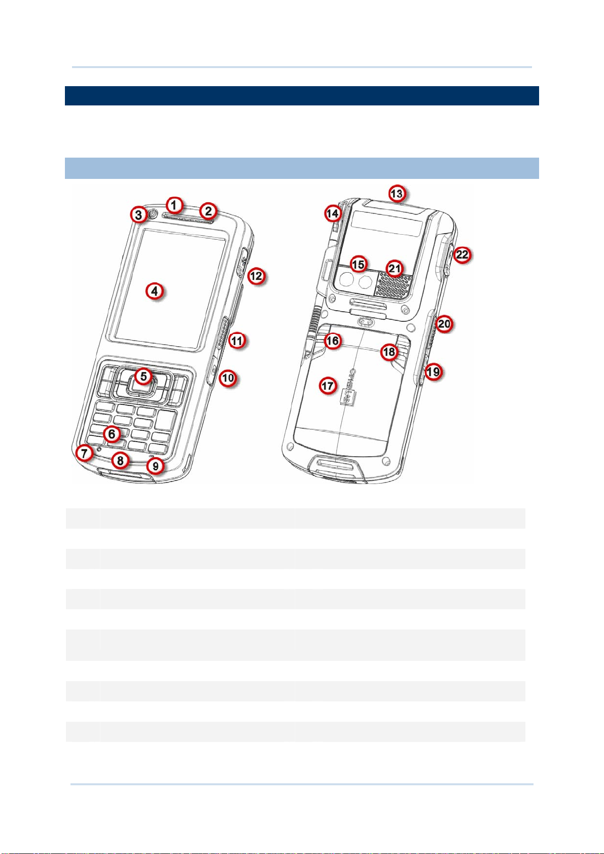
1.1.1. OVERVIEW
Figure 1: Overview
No. Description No. Description
1 Status LED 2 Receiver (Reserved)
3 Power key 4 Touchscreen (QVGA)
5 Scan key 6 Keypad
7 Reset toggle (recessed in keypad) 8 Direct charging- & communication-port
9 Microphone (Reserved) 10 Camera shutter button
11 Side-trigger (user definable) 12 External GPS antenna MMCX connector
(sealed with hinged rubber)
13 Scan window 14 Stylus (with attaching cord)
15 Camera and flash 16 Battery lock
17 Battery door 18 Battery release (spring loaded)
19 Volume rocker 20 Side-trigger (user definable)
21 Speaker 22 Headset jack (sealed with hinged rubber)
4
Page 21
Chapte
r
1
r
Use Mobile Compute
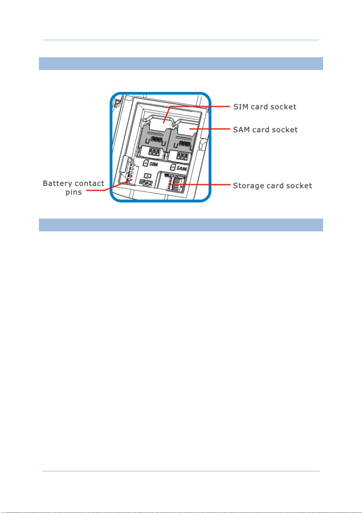
1.1.2. INSIDE BATTERY CHAMBER
Inside the battery chamber of the mobile computer are the sockets for SIM card and storage
card. Each is equipped with a hinged cover.
Figure 2: Inside Battery Chamber
1.1.3. BEFORE INITIAL USE
Prior to using the mobile computer for the first time, we recommend applying the protective
film over the LCD. This will prevent scratching the touchscreen during daily usage, and also
help enhance the durability of the touchscreen.
To apply the LCD protective film:
1) Upon delivery, the touchscreen of the mobile computer is covered with a thin
transparent film. Peel off and discard this film.
2) Wipe the touchscreen with a clean, non-abrasive, lint-free cloth.
3) Carefully apply the LCD protective film to the touchscreen by aligning its edges with the
edges of the touchscreen. Make sure the film adheres tightly to the surface.
The mobile computer is then ready for usage.
5
Page 22
CP55 Mobile Computer
Tap
Tap
Reference Manual
1.2. POWER ON/OFF MOBILE COMPUTER
POWER ON
To power on the mobile computer, press the Power button on the upper left corner.
The mobile computer powers on.
Note: For the mobile computer to power on, the battery cover must be secured in place.
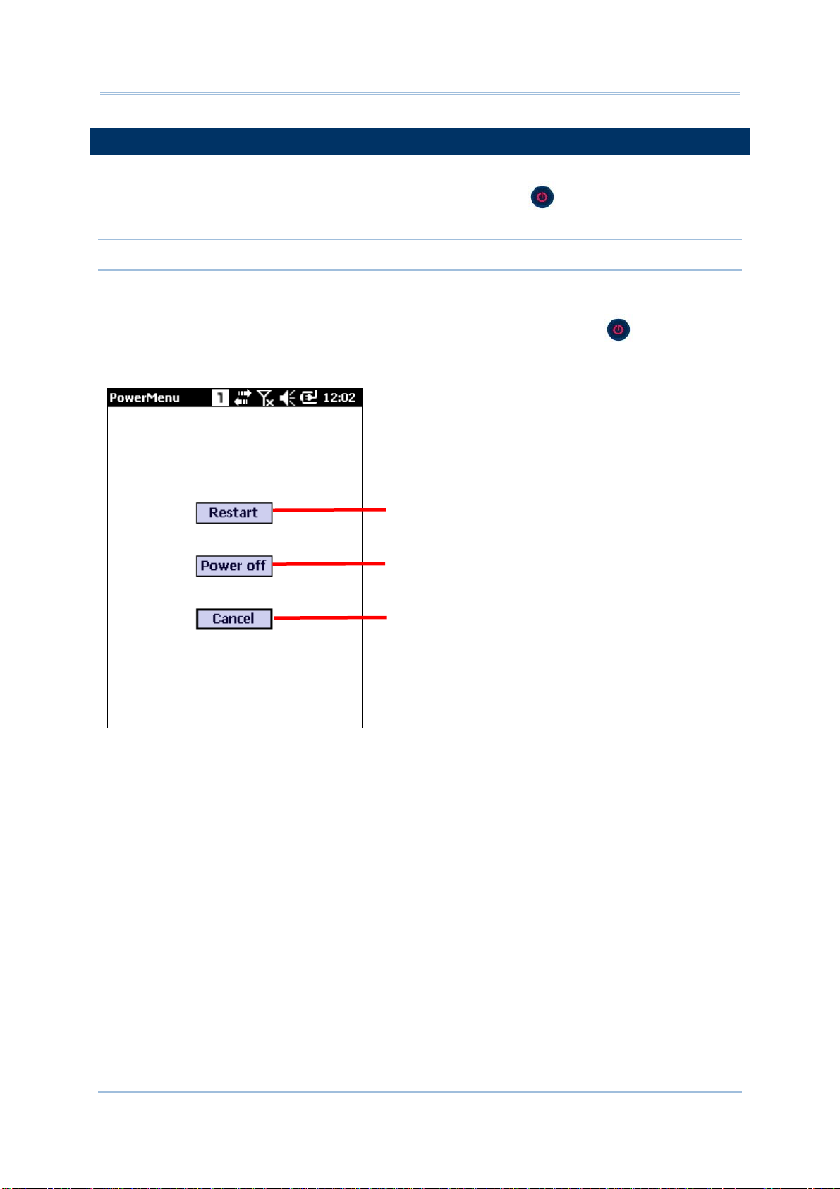
POWER OFF (VIA POWER MENU)
To power off the mobile computer, press and hold the power button for more than
three seconds. A power menu appears with two options for selection between restart and
power off. Make sure all user data and tasks have been stored before tapping Power off.
to restart the mobile computer
to power off the mobile computer
Tap to cancel and return to previous
screen
6
Page 23

Chapte
r
1
r
Use Mobile Compute
1.3. NOTIFICATIONS
The mobile computer features visible, audible, and tactile feedback to draw users’ prompt
awareness of the mobile computer’s contiguous events such as barcode reading,
wireless/mobile data connections, and battery charging.
STATUS LED
Three LED lights are located on the upper-right corner of the mobile computer. Their
functions are:
Matter
Scanning
Good Read
(Left)
Battery
Charging
(Middle)
Radios
(Right)
LED Color Action Description
Indicates good reading of the scanned barcode.
Green
Green, Red
Blue Blinking Wi-Fi, Bluetooth or mobile data in use.
Green, flashes once
Green, solid Battery is fully charged.
Red, solid Battery is charging.
Red, fast blinking
continuously
Enable/Disable this LED light on the Reader
Config
good read LED via API deployment, see the
CP55 Programming Guide for details.
Charging error, such as abnormally high/low
charging temperature, or A/C adaptor plugged
in but battery absent.
Notification Settings page. To set the
SPEAKER
The mobile computer has a speaker on the back for audio signaling and playback.
The speaker sounds for system events, application warnings, on-screen item selection and
physical keypad stroke. In noisy environments, the speaker remains efficacious with the
help of a Bluetooth headset. To control sound volume, see
Volume Control.
The speaker also sounds for successful barcode reading, which can be controlled on the
Reader Config
Notification Settings page.
VIBRATOR
The mobile computer owes its tactile feedback to the vibrator built inside. Vibration
delivered to the mobile computer alerts users of its currents status.
Working based on user’s sense, the vibrator is particularly helpful when the mobile
computer is serving in a noisy environment.
Same as the speaker and LED light, the vibrator also works for good barcode reading.
Enable/disable vibration and set its duration on the Reader Config
page. Alternatively, program the vibrator through API deployment to have it vibrate when
a successful reading occurs. See the CP55 Programming Guide for details.
7
Notification Settings
Page 24
CP55 Mobile Computer
Reference Manual
1.4. BATTERY
The CP55 mobile computer is fed by two batteries, main battery pack and backup battery.
The main battery is removable and replaceable from the battery chamber while the backup
battery is mounted on the main board inside the mobile computer.
When the mobile computer is shipped, the main battery is stored in a package separated
from the mobile computer, which keeps it in good condition for future use.
MAIN BATTERY
The main battery is a Li-ion 3.7V, 3300mAh battery pack, which takes around 4 hours to
charge to full. The working time of the mobile computer varies by its working states. A
battery icon seated on the taskbar will show the remaining
Main Battery Level.
See also
Main Battery Setup for installing the main battery.
BACKUP BATTERY
The backup battery is settled on the main board inside the mobile computer. It is a 15 mAh
rechargeable Lithium battery. When the main battery is absent or depleted, the backup
battery takes over to feed the mobile computer. Without the main battery, a fully charged
backup battery retains the data in the DRAM and holds the system in suspension for 30
minutes (as long as wireless modules are inactive).
The backup battery is rechargeable by the external power (through a power adapter) or
main battery pack. It takes about 8 hours to charge it to full. See
Note: When removing the main battery pack, actual data retention time will depend on the
backup battery level. Check backup battery level before replacing the main battery
to ensure your data is retained.
Backup Battery Level.
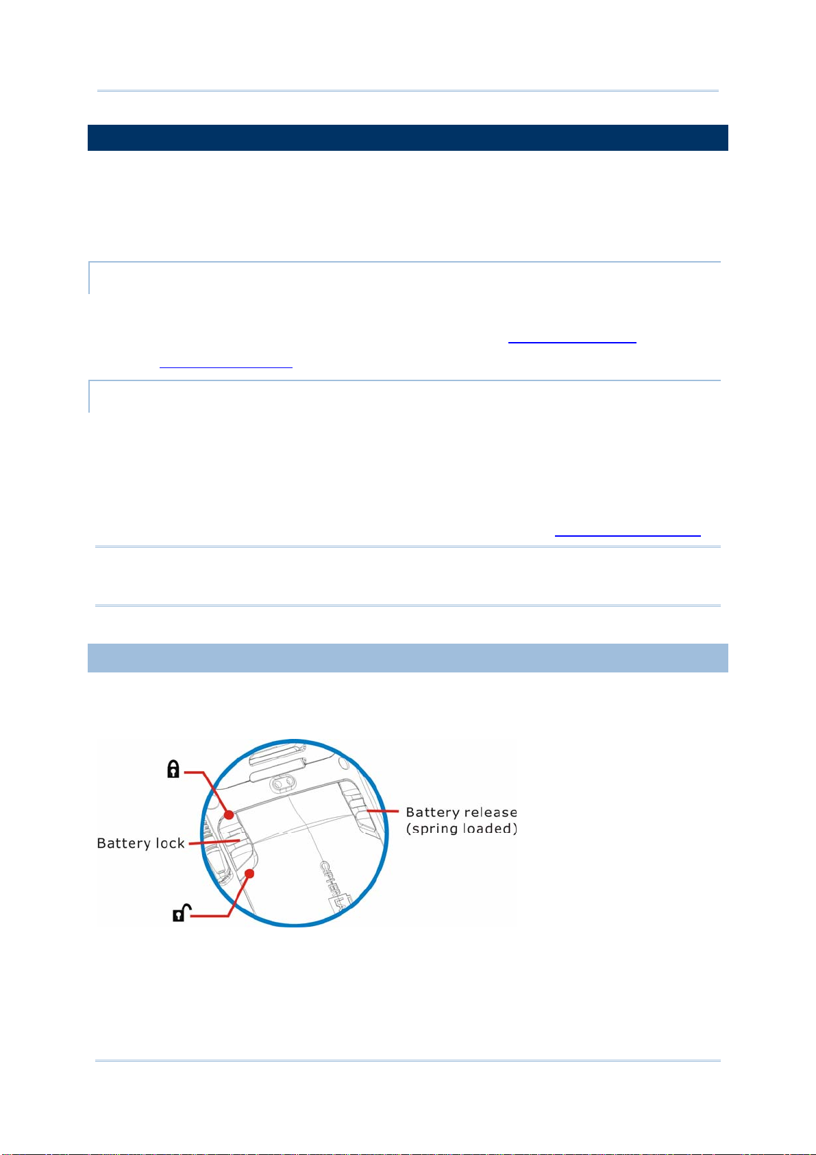
1.4.1. MAIN BATTERY SETUP
To secure the main battery in place, the battery door is equipped with two latches, one for
battery lock and one for battery release. Battery lock door latch has to be manually closed,
while the battery release door latch is spring-loaded and closes automatically.
8
Figure 3: Battery Door Latches
Page 25
Chapte
r
1
r
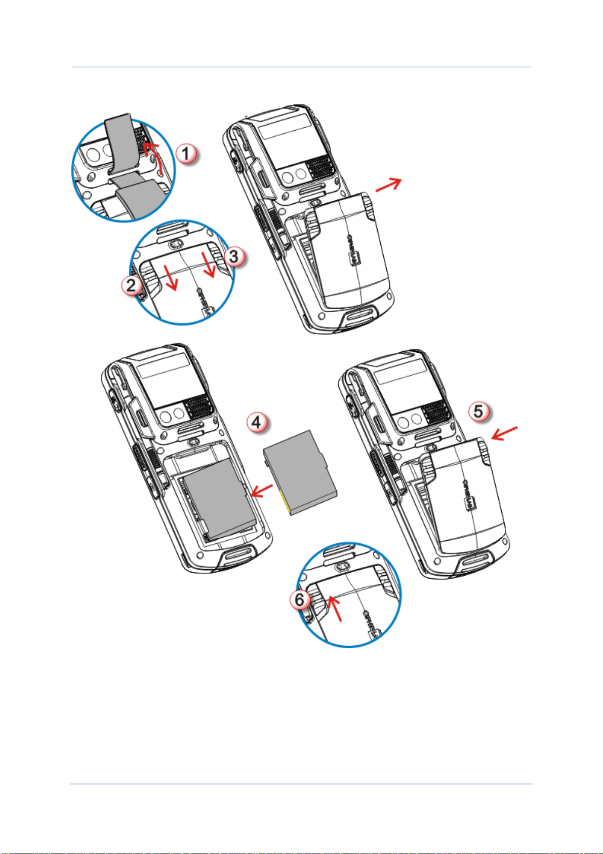
To install the main battery pack, follow through the steps below:
Use Mobile Compute
Figure 4: Main Battery Setup
1) Remove the handstrap.
2) Push the battery door lock (left) to “unlock” position.
3) Push back the battery release button (right). The battery door opens automatically.
Detach the battery door to reveal the battery chamber.
4) Insert the main battery pack into the battery chamber by meeting the connecting points
on the edge with the battery contact pins inside the chamber.
9
Page 26

CP55 Mobile Computer
Reference Manual
5) Replace the battery door by fixing the lower edge first, and pushing the release button.
6) Push the battery lock back to “lock” position.
Note:
(1) When main battery level drops to low level, charge it ASAP or replace it with a
charged battery.
(2) Always turn off the mobile computer to replace the main battery pack.
(3) The battery door must be secured in place for the mobile computer to operate.
(4) Any improper handling may reduce battery life.
1.4.2. CHARGE BATTERIES
Due to shipment, it is likely that the main battery and backup battery won’t be fully charged
when you receive the package. Before setting the mobile computer to work, charge the
main battery to full by direct charging via a power adapter (with the help of a Snap-on
Charging & Communication Cable or Charging & Communication Cradle).
Some key facts about charging batteries:
Charging Time
Main battery: It takes approximately 4 hours to charge the main battery. The battery charging
LED above the touchscreen lights red during charging, and lights green when the mobile
computer is completely charged.
Backup battery: The backup battery is rechargeable by both the main battery and power
adapter. It takes about 8 hours to charge it to full, however it does not need to be fully charged
for the mobile computer to work.
Charging Temperature
It is recommended that batteries be charged at room temperature (18°C~25°C) for optimal
performance.
Charging stops when temperature drops below 0°C or exceeds 40°C. In this case the battery
charging LED will be continuously blinking in red.
Power Consumption
When all radios (802.11 a/b/g/n, Bluetooth, mobile data (HSPA), GPS) are active on battery
power, main battery level drops substantially.
In order to prevent the system from shutting down due to depletion of the main battery, we
suggest that you keep a fully charged battery for replacement or have the mobile computer
access the radios on external power.
The following guides how to charge batteries.
10
Page 27
Chapte
r
1
r
Use Mobile Compute
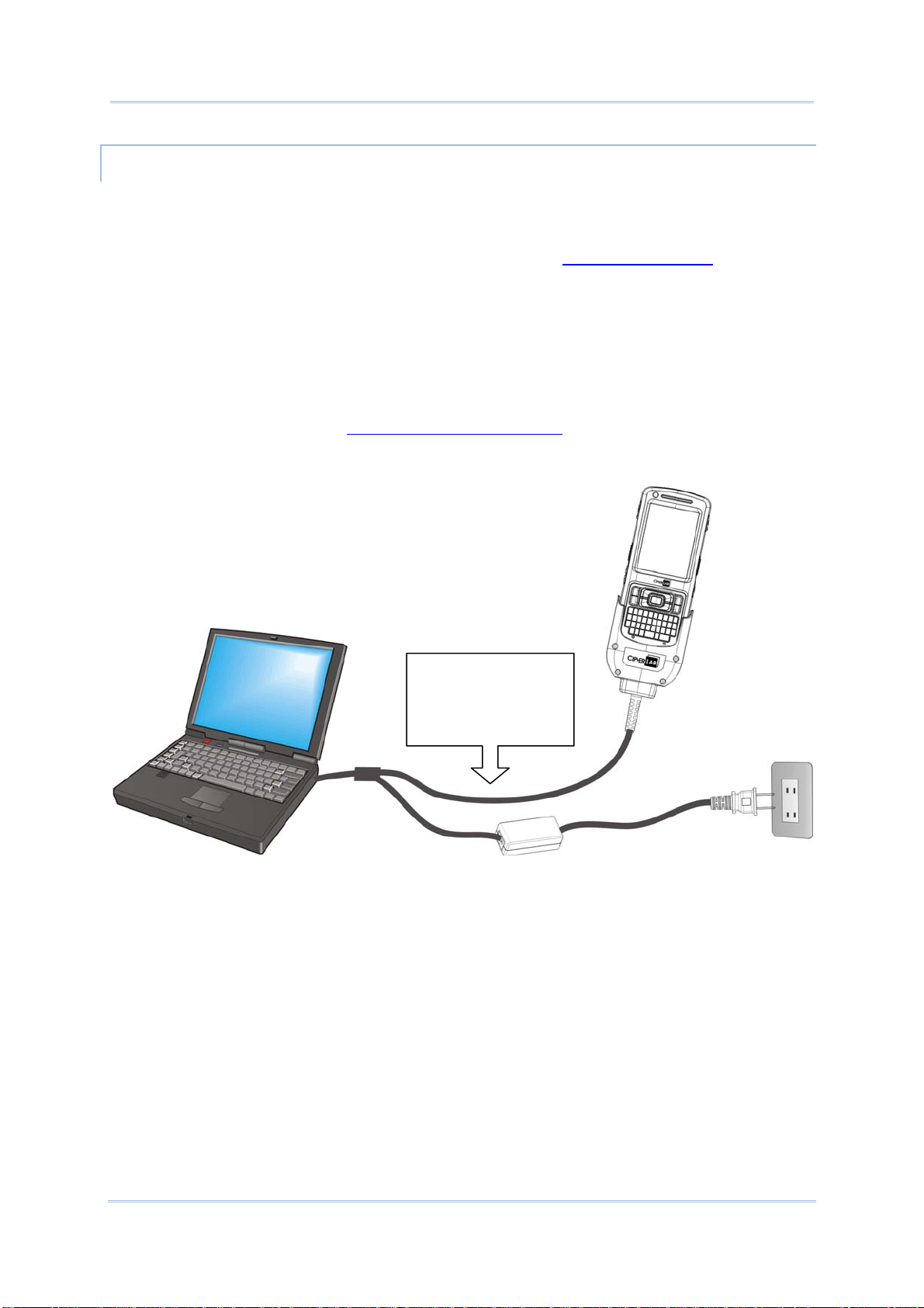
DIRECT CHARGING USING SNAP-ON CABLE
Direct charging of the mobile computer relies on the Snap-on Charging & Communication
Cable (hereinafter “snap-on cable”). There is a power jack on the connector of this cable to
connect external power.
Prior to charging, install the main battery as described in
the steps below:
1) Attach the snap-on cable to the mobile computer.
2) Plug the head of the power adapter cord into the power jack located on snap-on cable’s
connector.
3) Connect the power adapter to a power outlet.
To output data to your PC or laptop, connect the snap-on cable (either through USB or
RS-232 connection) to it. See
Direct Data Communication for follow-ups.
To transmit data,
connect the other end
of the Snap-on Cable
to your PC
Main Battery Setup. Then follow
Figure 5: Direct Charging Using Snap-on Cable
11
Page 28
CP55 Mobile Computer
Reference Manual
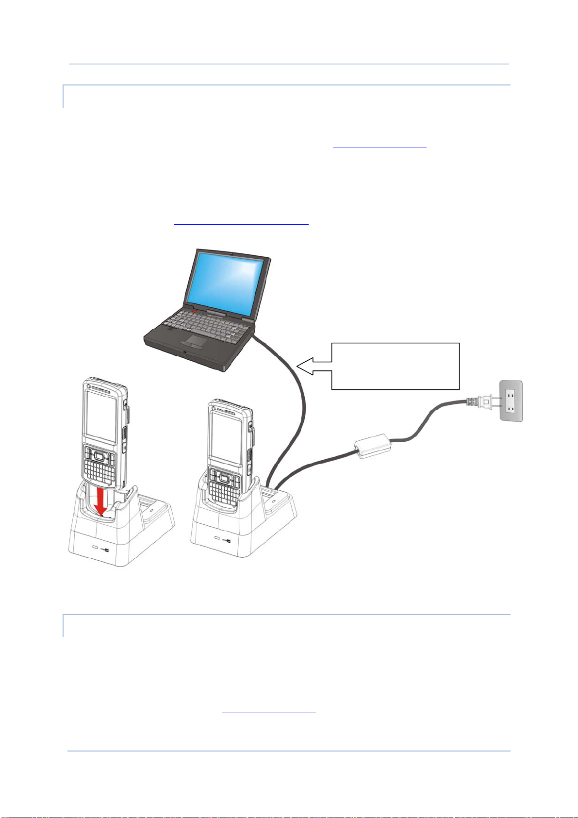
DIRECT CHARGING USING CRADLE
Direct cradle charging makes use of a Charging & Communication Cradle (hereinafter
“cradle”). The cradle is one of the accessories you can opt for.
Prior to charging, install main battery as described in
Main Battery Setup. Then follow the
steps below:
1) Seat the mobile computer into the cradle.
2) Connect the cradle to an external power source using the power adapter.
To output data to your PC or laptop, connect the mobile computer and your PC with a
microUSB cable. See
Direct Data Communication for follow-ups.
To transmit data, use the
microUSB cable to connect
the Cradle to your PC
Figure 6: Direct Charging Using Cradle
REPLACE MAIN BATTERY PACK
The Charging and Communication Cradle holds a separate charging compartment for the
main battery pack. This allows the mobile computer and a separate main battery pack to be
charged either individually or simultaneously. We advise you to keep a fully charged battery
at hand at all times.
Before replacing the main battery pack, turn off the mobile computer. Insert a charged
main battery pack as shown in
12
Main Battery Setup and power on the mobile computer.
Page 29
Chapte
r
1
r
Use Mobile Compute
1.4.3. MONITOR BATTERY LEVEL
The main battery is the only source that feeds the mobile computer to work. It also supplies
the backup battery on main board to retain the data stored in DRAM. Hence when main
battery level gets low, recharge it or change it as soon as possible. Most critically, back up
the important data from time to time to protect your work.
MAIN BATTERY LEVEL
To check the main battery level:
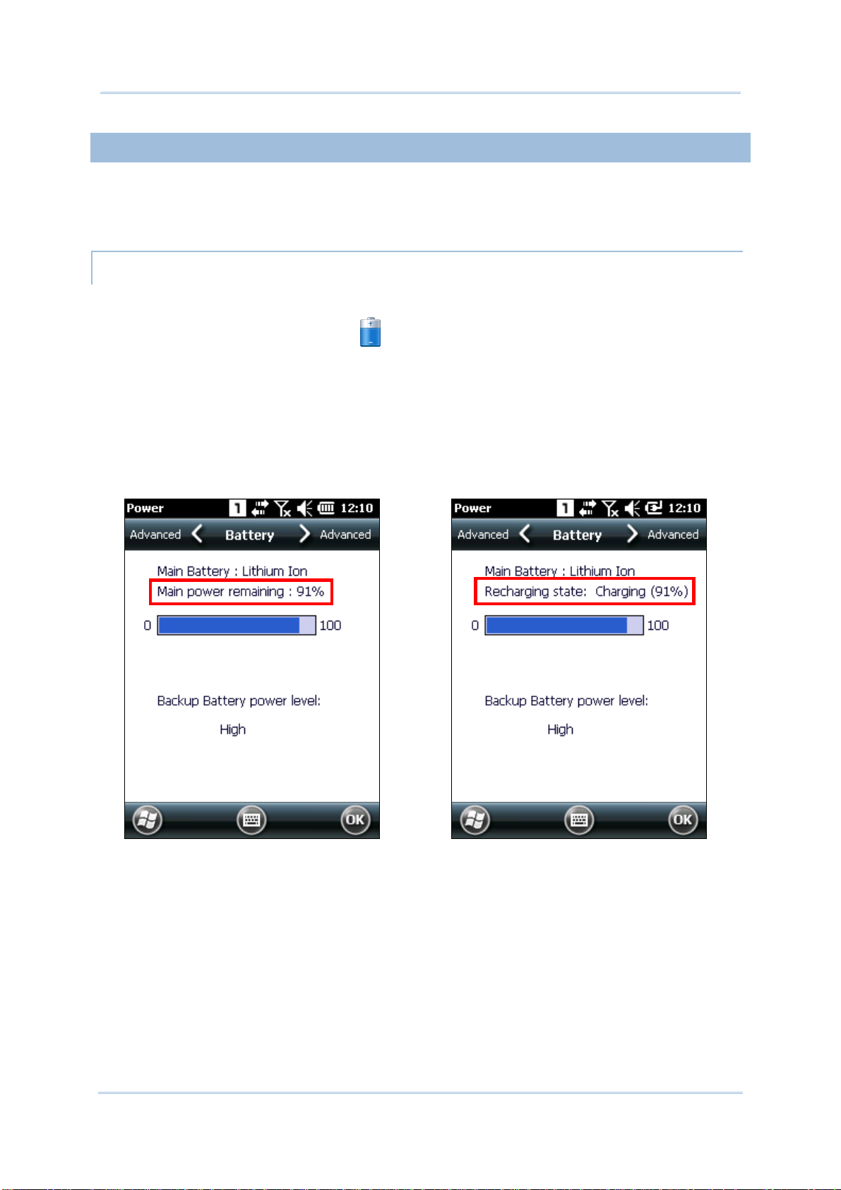
1) Tap Start | Settings | Power
.
Power Properties window opens showing Battery tab page. Precise battery level is
shown in percentage under the Main battery label.
Depending on whether the main battery is being charged, charging status will show
“Main power remaining”, meaning the mobile computer is on battery power, or
“Recharging state: Charging”, meaning that external power is connected.
Main battery isn’t being charged.
Main battery is being charged.
13
Page 30
CP55 Mobile Computer
Reference Manual
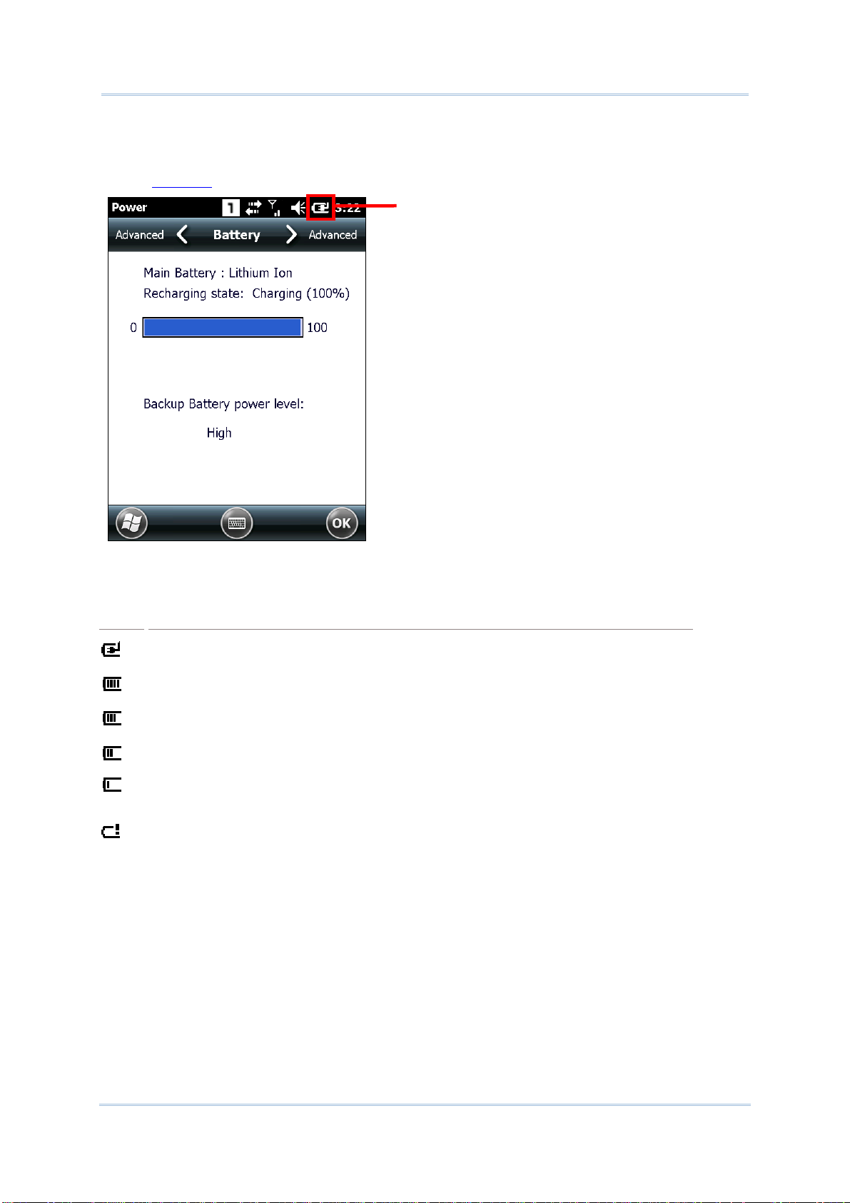
BATTERY STATUS ICONS
The OS features a couple of icons that deliver main battery status. These icons can be found
on the
Title Bar.
Battery status icon
Battery level is illustrated by the following icons:
Icon
Battery Status
Main battery is being charged from external power.
Main battery level is 80% to full.
Main battery level is partially drained between 60%-79%.
Main battery level is between 40%-59%.
Main battery level is between 20%-39%.
Main battery has dropped between 1%-19%. Battery needs charging
immediately.
14
Page 31

Chapte
r
1
r
Use Mobile Compute
LOW BATTERY ALERT
When main battery level drops below 40%, the mobile computer prompts “Main Battery
Low” for a recharge. When further reduced to under 20%, the mobile computer prompts
“Main Battery Very low” to solicit your immediate action.
Low battery may incur shutdown to the mobile computer and cause DRAM data damage.
Always save data before running short of power or keep a fully charged battery at hand for
replacement.
Note: Constant usage of the mobile computer at low battery level can affect battery life. For
maximum performance, recharge the battery periodically to avoid battery drain out
and maintain good battery health.
When main battery drains out, the mobile computer shuts down automatically. Backup
battery takes over to hold DRAM data for 30 minutes if it is fully charged. When this occurs,
replace main battery pack immediately to avoid data loss.
15
Page 32

CP55 Mobile Computer
Reference Manual
BACKUP BATTERY LEVEL
1) To check backup battery level, tap Start | Settings | Power .
On Battery tab page of Power Properties window, backup battery level is
summarized as “High”, “Low” or “Critical” under the Power label.
Backup battery level descriptions are as follows:
Description Battery Status
Backup battery level is good.
Backup battery level is low. Charging is recommended.
Backup battery level is very low and needs to be charged immediately.
High
Low
Critical
16
Page 33

Chapte
r
1
r
Use Mobile Compute
LOW BATTERY ALERT
When backup battery level drops to “Very Low”, the mobile computer prompts a “Backup
Battery Very Low” warning to alert users that backup battery level is almost drained out.
Backup battery is rechargeable by the main battery pack or the power adapter. Low backup
battery puts DRAM data in great danger. Remember to save data from time to time or keep
a fully charged battery at hand for replacement.
Once backup battery drains out completely, the data in DRAM is gone. Any data that has not
been saved will be lost!
1.4.4. POWER MANAGEMENT
Power issues are critical for portable devices. Always turn off the features you don’t need on
the mobile computer in order to save power. To extend battery life as long as possible,
always take the following actions:
Suspend the mobile computer when it isn’t actively in use. See
Computer
Turn down LCD backlight brightness as described in
LCD timeout as described in
Auto Sync the mobile computer with your PC less frequently. See
Communication
If you are using any “push e-mail” or any automatic syncing service on the mobile
computer, change the syncing schedule to manually check updates
When Wi-Fi, Bluetooth, mobile data (HSPA), or GPS isn’t in use, turn it off. See
Adjust Backlight, and set a shorter
Suspend Mobile Computer
Suspend Mobile
Direct Data
Radios
17
Page 34

CP55 Mobile Computer
Reference Manual
1.5. KEYPAD
The mobile computer has a physical keypad and a touchscreen to receive user’s input.
Among the two, the touchscreen provides more intuitiveness in interacting with the device.
This section shows how to input text using physical keypad and on-screen keyboard. To
know how to operate the mobile computer using the touchscreen, see
Touch Control.
1.5.1. PHYSICAL KEYPAD
The physical keypad on the front of the mobile computer bears much resemblance to laptop
or PC keyboards. It is either a numeric type or a QWERTY one, each wedging a set of
“enhanced keys” along the top and a set of character keys at the lower half. Both keypads
support multi-key operation, which normally requires two keys hit simultaneously, one of
which is a modifier key.
As for entering text, the numeric and QWERTY keypad are equally capable of entering
numbers, letters, symbols and punctuation marks. Both also receive supplementary
backlight along with the screen.
Figure 7: Numeric Keypad Figure 8: QWERTY Keypad
ENHANCED KEYS
Enhanced keys are arranged along the top of the physical keypad, separate from the
character keys. Use these “enhanced keys” to launch actions on the mobile computer and
OS, operate the active application, or switch the physical keypad between input modes.
Navigation keys are included also to move the caret in a text input field, and to select
between applications on the desktop.
Figure 9: Enhanced Keys
18
Page 35

Chapte
r
1
r
Use Mobile Compute
Enhanced keys can be categorized into five groups and are explicated as follows:
Key Group
ACTION KEYS
OS KEYS
Description
The Scan key is an action key which delivers the function below:
Key Press
Scan Key
The following tabulates OS keys and their functions. Some of them are engraved
in orange, which means
the keys to function properly.
Reads barcodes
Function Key needs to be pressed beforehand in order for
Key Press
Windows
Opens . (Requires
Confirms input in an input field. (Requires Function Key
pressed beforehand.)
Function Key pressed beforehand.)
Delivers the same function as the “OK” button on the title
bar of the active window. (Requires
beforehand.)
Send Key available for function assignment in CipherLab utility
Button Assignment.
End Key available for function assignment in CipherLab utility
Button Assignment.
Function Key pressed
NAVIGATION KEYS
FUNCTION KEY
[ALPHA] KEY
Opens the previous screen worked on.
Closes a menu of an application, or an opened dialog.
Tab
Navigates among the highlight items in some applications.
Enters Tab character, which means it moves the caret to
The buttons encircling the Scan key are the up/down/right/left navigation keys:
They move the caret in an input field. In certain applications, they navigate
vertically or horizontally among highlighted items.
Function key applies its action when used in conjunction with other keys.
Together they make the OS take actions or produce functions through
and more.
When other text input modes are activated at the moment, pressing the Fn key
will alter the input mode and the icon on the taskbar. See
[Alpha] key switches the keypad input mode between numeric mode and
alphabetic mode.
the next tab stop.
Function Key.
19
Page 36

CP55 Mobile Computer
Reference Manual
NUMERIC KEYPAD
Numeric keypad wedges a set of character keys at the lower half. They are laid out similar
to a telephone keypad, and additionally featured are an Esc key, Tab key, Enter key,
Backspace key, and Shift key that enable more sophisticated text input.
Numeric keypad enters numbers 0 through 9 by default. Symbols * through ) and
alphabetic characters can be entered by combined use of the Alpha key and Shift key.
QWERTY KEYPAD
QWERTY keypad also arranges its character keys in the lower half and features them in a
compact “QWERTY” layout as its name suggests.
QWERTY keypad is a pared down version of an average laptop’s keyboard that bears also an
Esc key, Tab key, Enter key, Backspace key, Shift key, and space key.
20
Page 37

Chapte
r
1
r
Use Mobile Compute
ALPHA KEY
By default, the numeric keypad is set to numeric mode, and the QWERTY keypad is set to
alpha (lowercase alphabetic) mode. The Alpha key [α] serves as a switch key between
numeric and alphabetic input modes.
The status icon on the taskbar delivers the current input mode:
Status Icon
Alpha Key Input Mode
On QWERTY keypad, press [α] once Numbers
On numeric keypad, press [α] once Lowercase alphabetic characters
Note:
(1) The Alpha key [α] can be used to switch between alpha and numeric input
modes
(2) If you are using the on-screen keyboard, tap CAP (Caps Lock) to switch between
uppercase and lowercase alphabetic modes.
SHIFT KEY
The Shift key induces the following changes to input mode:
Status Icon
→
→
Shift Key Input Mode
Press [×] once The Shift key [×] modifies the next key pressed depending
on the input mode.
(1) In numeric mode (
pressed. However, the actual content input is not affected.
(2) In alpha (lowercase alphabetic) mode ( ), it will
show a single uppercase character after pressing Shift key
[×] one time.
For example, input “ABC”, and it will show “Abc.
), it will act on the next key
→
→
Press [×] twice
(enter Shift Lock Mode)
Pressing Shift key [×] two times will lock the present input
mode.
(1) In numeric mode (
However, the actual content input is not affected.
(2) In alpha (lowercase alphabetic) mode (
uppercase alphabetic mode (= Caps Lock).
For example, input “ABC”, and it will show “ABC”.
), it will lock numeric mode.
), it will lock
Note: There is no need to long press the Shift key [×].
21
Page 38

CP55 Mobile Computer
Reference Manual
FUNCTION KEY
The Function key [Fn] serves as a specified key, and the functionality of each key
combination is application-dependent.
1) To enable this special key, press [Fn] on the keypad. Its icon
will appear on the
status bar.
2) Now press another key to get the value of key combination (say, press [1] to get the
value of F1).
3) To get the value of another key combination specified by the function key, repeat step
2.
4) To disable the special key function, press [Fn] again, and the icon
will go off.
Note: There is no need to long press the [Fn] key.
22
Page 39

Chapte
r
1
r
y
Use Mobile Compute
1.5.2. ON-SCREEN KEYBOARD
The OS provides users with an on-screen keyboard. Compared to a physical keypad, the
on-screen keyboard bears likeness to a laptop keyboard as it has modifiers keys arranged
on the left edge and features a “QWERTY” layout. The on-screen keyboard supports
entering a series of diacritics for European languages by tapping a modifier key.
The on-screen keyboard auto-opens in some applications while in others it doesn’t unless
you tap on a field that accepts input.
In case the on-screen keyboard doesn’t open automatically, tap the keyboard icon
on
the softkey bar. When opened, the on-screen keypad is ready to enter lowercase letters,
numbers, and a few frequently used symbols.
On-screen
keyboard opens.
Backspace
Caps Lock
Shift key
Ctrl key
Enter ke
Navigation keys
Input modifier
Opens menu to hide
on-screen keyboard
Space bar
23
Page 40

CP55 Mobile Computer
Reference Manual
MODIFIER KEYS
Although the touchscreen is a resistive single-touch type, use of modifier keys, which
normally involves hitting two keys, are still available on the on-screen keyboard.
On the on-screen keyboard there are four modifier keys, which are seated at the left edge.
These keys work as follows:
1) Press a modifier key on on-screen keyboard.
The on-screen keyboard enters modifier state.
2) Press the second key.
The desired performance will be produced to the active application or screen at the
moment.
Modifier keys are explicated as following
Key
Ctrl key
Shift key
Caps Lock
Input
modifier
Description
Once tapped, it becomes color-inverted
active application when a character key is tapped. It quits once the said action is
triggered or when it is tapped again.
For example: Tap
Windows environment usually selects all content on the active screen. Once “A” is
tapped, the on-screen keyboard quits Ctrl state.
Once tapped, it becomes color-inverted and capitalizes the (one) letter typed. It
quits once a character key is tapped or it is tapped again.
To enter all caps, use Caps Lock
Once tapped, it becomes color-inverted and capitalizes all the alphabetic
characters typed. It doesn’t quit until it is tapped again.
This key does not affect numbers, punctuation marks, or symbols.
Once tapped, it becomes color-inverted
such as ä, æ, ë, ï, ö, ú or letter variants such as ß and ç which are needed for European
languages. It quits once a character key is tapped.
key and then tap key “A” to produce Ctrl+A function, which in
and causes a special action from OS or the
.
and presents a series of accented vowels
24
Page 41

Chapte
r
1
r
2
Use Mobile Compute
Tap key on on-screen keyboard.
1
key becomes color-inverted .
Then tap a character key.
Letter variant “ü” is entered
After the letter variant “ü” is entered,
the on-screen keyboard restores to
normal English alphanumeric layout.
Diacritical letters and letter variants are presented bother lowercase and
uppercase.
25
Page 42

CP55 Mobile Computer
Reference Manual
OTHER KEYS
Lowercase
Uppercase
Key Description
Tab key
Backspace
Enter key
Navigation keys
Spacebar
Navigates among the highlight items in some applications. For text input, it
inserts Tab character, which means it moves caret to the next tab stop.
Erases the characters to the left of caret.
Executes a command or confirms input. When text input, it inserts a break
between paragraphs.
Move caret in an input field. In certain applications, they navigate vertically or
horizontally among highlight items.
Inserts a blank space where caret is.
26
Page 43

Chapte
r
1
r
Use Mobile Compute
CHANGE KEYBOARD ORIENTATION
The mobile computer is built-in with a G-sensor and supports screen orientation, which is
enabled by default. So when the mobile computer turns sideways or upright, the screen
changes its orientation, and on-screen keyboard also readjusts itself to the new orientation.
Upright (Portrait Mode) Sideways (Landscape Mode)
To disable automatic screen rotation, see Screen Orientation.
27
Page 44

CP55 Mobile Computer
Reference Manual
1.5.3. EDIT TEXT
On the mobile computer, cut, copy, and paste text within an application or across
applications by the menu commands. Some applications don’t support editing some or all of
the text they display while others may offer their own way to edit text.
EDIT TEXT IN INPUT FIELDS
To edit text in a text input field:
1) Tap where you want to edit text.
Caret moves to the desired place and manifests itself as a vertical bar that blinks to
indicate where the typed or pasted text will be inserted.
2) Type, paste or delete text.
To paste text, see
Paste Text.
SELECT TEXT
When you see some text on a page you want to copy, select it first by tapping and dragging
the caret so the desired text is highlighted.
CUT OR COPY TEXT
After a text is selected, tap the Edit menu on the title bar of the active window to open an
option menu that includes Copy/Cut commands. Tap them to copy/cut the selected text.
PASTE TEXT
Within the OS, texts can be copied to and from certain applications.
To paste text:
1) Tap the text field where you want to paste the text.
2) Tap the Edit menu on the title bar of the active window and select the Paste command.
28
Page 45

r
1
r
Chapte
Use Mobile Compute
1.6. TOUCH CONTROL
The mobile computer’s LCD is overlaid by a resistive touch panel and thus forms a resistive
touchscreen. Since a resistive touchscreen locates the user’s touch by the force applied on
it, by operating with the stylus one can apply minimum force to trigger actions from the
touchscreen.
Touch control is one of the main ways to interact with the mobile computer. It provides the
ability to manipulate icons, buttons, menu commands, the on-screen keyboard, or any
on-screen items.
1.6.1. USE TOUCHSCREEN
The mobile computer comes with a stylus. Use it to touch-operate the mobile computer.
Apply the gestures below to work on the touchscreen:
Tap – Touch any item on the screen such as an application icon or a setting icon to work
on it, or touch any key on the on-screen keyboard to type it.
Tap and hold – Touch an item on the screen and do not release until an action occurs.
Drag – Touch and hold an item for a moment and then, without release, move the item
on-screen until you reach the target.
Double-tap – Touch quickly twice on certain screens to zoom. For example, double-tap
a section of a webpage in a web browser to zoom that section so it fits the width of the
screen. Some applications such as map-info applications support picture zooming with
double-tap.
Rotate screen – On most screens, the screen rotates as the mobile computer changes
its orientations between upright and sideways.
1.6.2. SCREEN ORIENTATION
The mobile computer has a built-in G-sensor for screen orientation. In order to enable
automatic screen orientation:
1) Tap Start | Settings | System | Screen Rotation
.
29
Page 46

CP55 Mobile Computer
T
Reference Manual
Screen Rotation window opens with three orientation modes to select from and an
option to suspend the mobile computer when the screen is facing down.
Three screen orientation
modes
Allows mobile computer to
enter suspension when
facing down
2) Tap the modes that you wish to enable. The tapped item will light up to indicate it is
currently enabled.
apped items will light up
3) Tap OK on the title bar to apply the changes.
The mobile computer will then automatically switch between the enabled modes
according to its physical orientation. For instance, if Portrait and Landscape modes
are enabled, the touchscreen will switch between upright and sideways view according
to the user’s holding position. However, if only Portrait (upright) mode is enabled, the
touchscreen will stay in upright mode regardless of the mobile computer’s orientation.
30
Page 47

Chapte
r
1
r
Use Mobile Compute
SIGNATURE MODE
The signature mode is for combined usage with the CipherLab application Signature. With
this mode enabled, the screen will immediately rotate 180° when the front of the mobile
computer is tilted outwards, which is convenient for signing by a second party.
Note: If no modes are selected in Screen Rotation, the mobile computer’s touchscreen
will be fixed in portrait mode.
1.6.3. ADJUST BACKLIGHT
Screen backlight can be adjusted manually or automatically. Upon shipping, the mobile
computer is set to automatic adjustment, which helps saves power. Alternatively you can
set the backlight manually according to your preferences.
MANUAL BACKLIGHT ADJUSTMENT
To adjust screen backlight:
1) Tap Start | Settings | System | Backlight .
Brightness tab page opens with a checkbox to enable manual backlight setting, and a
slider bar for setting screen backlight level.
By default, Manual backlight setting is checked, and LCD backlight will stay at the set
level and will not adjust automatically. When Manual backlight setting is unchecked,
the light sensor embedded on the front of the mobile computer will detect current
lighting environments, and LCD backlight will adjust automatically according to the
backlight profiles set under the Profile tab page.
Select whether to enable manual
backlight setting
Slide to set backlight level as desired
2) Tap OK to apply the settings.
31
Page 48

CP55 Mobile Computer
Reference Manual
AUTOMATIC BACKLIGHT PROFILES
The mobile computer stores three backlight profiles to represent backlight level under
different environments. These can be configured according to user’s likings.
To set backlight profiles:
1) Tap Start | Settings | System | Backlight .
2) Uncheck Manual backlight setting to enable profile function.
3) Switch to the Profile tab page.
Three profiles, Dark, Bright, and Brightest are available in the drop-down box. Select
the profile you would like to modify and use the slider bar below to set the backlight
levels to your preferences. The screen backlight will change temporarily to show the
effect.
To restore profile settings to default, tap the Default button at the top right corner.
Tap the drop-down box
to select between
different profiles
4) Tap OK to apply the settings.
Tap to restore the backlight
profile settings to default
Slide to set backlight
level as desired
32
Page 49

Chapte
r
1
r
Use Mobile Compute
1.6.4. CALIBRATION
A resistive touchscreen needs calibration to work accurately after serving for a period of
time. Calibration aligns the coordinates of the touch panel and the LCD underneath to
improve touch accuracy.
To calibrate the touchscreen:
1) Tap Start | Settings | System | Screen
.
2) Tap General tab page. Tap Align Screen button to open the calibration screen.
3) Using the stylus, tap firmly at the center of the cross that appears on-screen. Five
crosses will appear in sequence.
Follow the on-screen instructions to save the new calibration settings or restore the old
settings. Once completed, the screen returns to General tab page.
33
Page 50

CP55 Mobile Computer
Reference Manual
1.7. MEMORY
The mobile computer packs the following memory units to retain data and instructions from
users:
Random-access Memory (RAM)
512 MB SDRAM for temporary storage and fast access of active applications. When the
main battery pack is absent, SDRAM is fed by backup battery to retain data.
Internal Storage
4GB flash memory to store the OS (Windows Embedded Handheld 6.5), application files,
settings, and other data used by applications.
External Storage
Insert a storage card to increase the mobile computer’s storage capacity. Supported are
MicroSD cards from 256MB to 4GB, or MicroSDHC cards from 4GB to 32GB.
1.7.1. DATA LOSS CAUTION
When main battery is absent or used up, backup battery on the main board takes over to
supply power to the mobile computer. A fully charged backup battery retains SDRAM data
and suspends the mobile computer for 30 minutes.
Note if you are leaving the mobile computer to sit for a couple of days, data loss will occur
when both main and backup batteries drain out. Consider backing up data before putting
away the mobile computer.
1.7.2. CHECK STORAGE
INTERNAL STORAGE
To check internal storage size:
1) Tap Start | Settings | System | System
Information
revealing information about the mobile
computer’s assemblage and hardware/firmware
components, including device manufacturer,
device ID, memory size, and firmware/software
version. RAM and Flash size are also listed
among this info.
Expand to view information
on memory size
. The application opens
34
Page 51

Chapte
r
1
r
Use Mobile Compute
EXTERNAL STORAGE
Tap Start | Settings | System | Storage Information . The Storage Card label
shows the available space on the storage card (if no storage card is installed on the mobile
computer, the available size will be displayed as 0).
35
Page 52

CP55 Mobile Computer
Reference Manual
1.7.3. INSERT SD CARD
Day-to-day use of the mobile computer might cause the available internal storage to run
short. Equip the mobile computer with an external memory unit to expand storage capacity.
Follow the steps below to install a SD card:
1) Power off the mobile computer.
2) Place the mobile computer face-down on a flat and soft surface.
3) Remove the battery door and main battery pack as described in
4) Locate the SD card socket inside the battery chamber. (See
Inside Battery Chamber.)
The SD card socket is equipped with a hinged cover.
5) Push the hinged cover to the “open”
position.
6) The hinged cover is unlocked.
7) Swivel up the hinged cover.
8) Insert the SD card into the cover slot
in the direction indicated . The
metal contact pins should face down.
9) Put down the hinged cover and push
it back to the “lock” position.
10) Restore the main battery pack and
battery door.
Figure 10: Inserting SD Card
Main Battery Setup.
36
Page 53

Chapte
r
1
r
Use Mobile Compute
1.8. DIRECT DATA COMMUNICATION
“Direct” data connection means “hardwired” data connection between the mobile computer
and a Windows-based PC as opposed to wireless connection. Direct data connection relies
on a RS-232 cable or a USB cable (sometimes plus an auxiliary cradle) between the two
mentioned devices. Once the mobile computer and PC are “directly” connected with each
other by a RS-232 or USB-cable, they can sync data with each other.
1.8.1. USE SNAP-ON CABLE
Direct data communication using a cable:
1) Connect the mobile computer to your PC with a Snap-on Charging and Communication
Cable (either USB or RS-232 type) .
2) On the mobile computer, tap Start | Settings | System | USB Connection
3) To connect the mobile computer and PC via ActiveSync, select ActiveSync Serial
Mode.
To treat the mobile computer as an external storage device, select Mass Storage – SD
Card.
4) Tap OK on the title bar to apply the settings.
If one of the first two options are selected, ActiveSync will automatically detect
connection between the two and prompt for data synchronization.
See
Syncing Tools and subsequent sections to know how to use ActiveSync.
Note: The CP55 mobile computer uses COM9 for serial transmission via RS-232.
.
Figure 11: Direct Data Communication Using Snap-on Cable
37
Page 54

CP55 Mobile Computer
Reference Manual
1.8.2. USE CRADLE
Direct cradle charging makes use of a Charging & Communication Cradle (hereinafter
“cradle”). The cradle is one of the accessories you can opt for.
Prior to charging, install main battery as described in
Main Battery Setup. Then follow the
steps below:
1) Seat the mobile computer into the cradle. Connect one end of the USB cable to the
Cradle and the other end to the PC.
2) To charge the mobile computer, connect the cradle to an external power source using
the power adapter.
3) Tap Start | Settings | System | USB Connection
.
4) To connect to the PC via ActiveSync, chose ActiveSync Serial Mode.
To treat the mobile computer as an external storage device, chose Mass St orage – SD
Card. Note that Mass Storage is only supported when as SD card is installed on the
mobile computer.
5) Tap OK on the title bar to apply the settings.
If ActiveSync Serial Mode is selected, see
Syncing Tools and subsequent sections to
know how to use ActiveSync.
Note: The cradle supports USB Host Mode via a USB OTG cable.
Figure 12: Direct Data Communication Using Cradle
38
Page 55

Chapte
r
1
r
Use Mobile Compute
1.8.3. SYNCING TOOLS
Microsoft’s syncing tools enables users to update or back up the data on their mobile
computers to desktop computers.
Two syncing tools are featured by Microsoft - ActiveSync and Windows Mobile Device Center
(“WMDC”). Which tool to use depends on which OS is running on your PC. See the rule
below:
OS
Windows Vista or Windows 7
Windows XP SP3 and earlier
ActiveSync and WMDC can be downloaded from Microsoft’s website. Download and install
the right one on your PC.
Hereafter in this manual, we will focus on ActiveSync only. For WMDC usage, see its
documentation or help file.
Syncing Program
WMDC
ActiveSync
1.8.4. SYNC PARTNERSHIP
Once a direct connection is established between the mobile computer and your PC as
described in
Sync Partnership
Synchronization Relationship
Use Snap-on Cable, they are able to form the following ties:
Services
A l lows t h e mobil e c omput e r and PC t o sync d a t a wit h e a ch oth e r .
Allows PC to add and remove programs to/from the mobile
computer.
Allows PC to browse files on the mobile computer.
Allows PC to copy files to/from the mobile computer.
Allows PC to back up the files on the mobile computer.
Temporary Relationship
(Mobile computer works as a
“guest” to PC)
Allows PC to add and remove programs to/from the mobile
computer.
Allows PC to browse files on the mobile computer.
Allows PC to copy files to/from the mobile computer.
Allows PC to back up the files on the mobile computer.
Note that data stored on external storage (the SD card) cannot be synchronized.
See
ActiveSync Actions to Take for details about the mentioned services.
39
Page 56
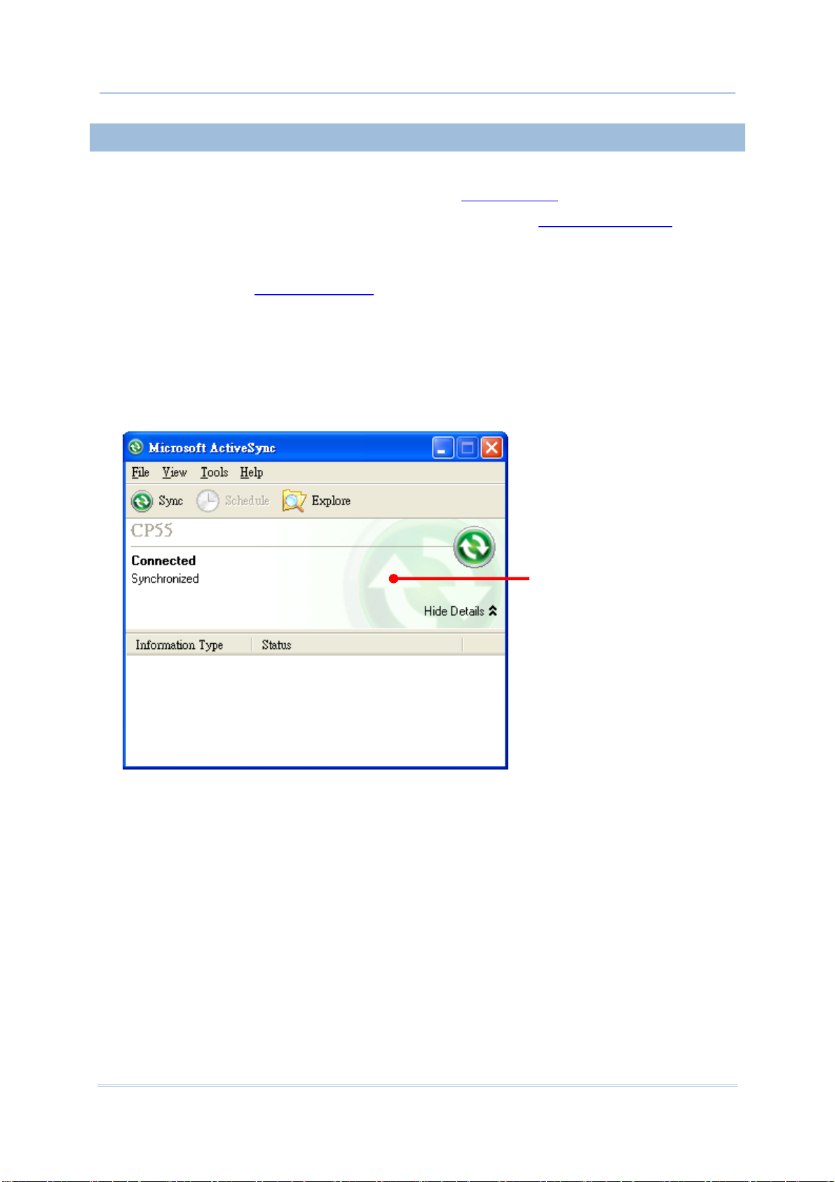
CP55 Mobile Computer
Reference Manual
1.8.5. 1ST USB SYNC
This section will guide you through USB syncing. To connect ActiveSync using USB:
1) Download the right syncing tool as described in
2) Connect the mobile computer and your PC as described in
3) On your PC, run the syncing program.
ActiveSync should detect the mobile computer. Sync Setup Wizard launches and
prompts to set up
4) Press Next for “Synchronization Relationship”, or press Cancel for “Temporary
Relationship” if you don't plan to connect to the PC on a regular basis.
If you have pressed Next, follow the on-screen instructions and select the data
categories you would like to synchronize. Once confirmed, synchronization will begin
shortly, and when the process is finished, ActiveSync window will show “Synchronized”
to indicate that the data on the mobile computer and PC are identical.
Sync Partnership between two computers.
Syncing Tools and install it on your PC.
Use Snap-on Cable.
A “Synchronization Relationship”
is established between the mobile
computer and the PC
OR
If you have pressed Cancel, Microsoft ActiveSync opens showing “Guest” and
“Connected”. The mobile computer and the PC are connected but the data is not
synchronized.
40
Page 57

Chapte
r
1
r
A “Temporary Relationship” is
established between the mobile
computer and the PC
Use Mobile Compute
Note: If you encounter trouble during USB ActiveSync connection, tap Start | Settings |
System | USB Connection and make sure “ActiveSync Serial Mode” is selected.
1.8.6. DISCONNECT USB ACTIVESYNC
To disconnect USB ActiveSync:
1) On your PC, open ActiveSync by double-clicking its icon
ActiveSync opens.
2) From the menu bar, click File | Connection Settings.
[Connection Settings] window opens.
3) Deselect Allow USB connections.
4) Press the OK button to apply the change and quit setting.
This way when you plug your mobile computer the next time, ActiveSync won’t attempt
to connect to it.
in the notification area.
41
Page 58

CP55 Mobile Computer
Reference Manual
1.8.7. ACTIVESYNC ACTIONS TO TAKE
Once “Synchronization Relationship” or “Temporary Relationship” is established between
two computers, a variety of actions can be taken to enhance resource sharing between
them as previously mentioned in
In summary, “Synchronization Relationship” outshines “Temporary Relationship” by being
capable of syncing Microsoft Office Outlook data. However “Temporary Relationship”
provides satisfactory file sharing if you don’t want to synchronize information.
See the following to know what actions to take with ActiveSync:
ADD/REMOVE PROGRAMS
Note basically the applications to be installed to the mobile computer need to be installed on
your PC first. So download the application programs to your PC first and install them on your
PC so they can be installed onto the mobile computer later.
Many application programs are installed in different ways. Read their installation guides or
documentation to know how they are installed. If you are installing an application that
cannot be installed on your PC first, try to install it right from the mobile computer. See
Download & Install Applications for more details.
Sync Partnership.
To install an application on the mobile computer:
1) Connect two computers as described in
2) Sync two computers as described in
Use Snap-on Cable.
1st USB Sync.
3) On the PC, from the menu bar of ActiveSync, select Tools | Add/Remove Programs.
ActiveSync starts to search for the application programs installed on your PC and opens
its [Add/Remove Programs] dialog which lists those found. Each entry comes with a
check box on the left. An unchecked box means the program is yet to install to the
mobile computer while a checked one means an installed program.
42
Page 59

Chapte
r
1
r
Use Mobile Compute
4) Select the application program(s) to install to the mobile computer, and deselect the
application program(s) to uninstall from the mobile computer.
5) Press the OK button.
ActiveSync proceeds to install programs and/or remove programs to/from the mobile
computer.
6) Follow the on-screen instructions on both your PC and the mobile computer to proceed.
Noteworthy facts:
Normally the application program(s) downloaded from external resources are installed
to the mobile computer’s directory at My Device\Program Files. However sometimes
there are exceptions and the actual situation depends on the application.
You can also uninstall applications directly on the mobile computer rather than on the PC.
See
Uninstall Applications for more details.
If you would like to uninstall a program that isn’t listed in the [Add/Remove Programs]
dialog, browse to it on the mobile computer by tapping My Device
on the
desktop. Tap and hold it, and select Delete from the context menu that pops up.
ADD APPLICATION SHORTCUTS TO START SCREEN
ActiveSync features “Explore” to add an application shortcut to Start screen where it is
easier to launch the application.
To add an application shortcut to Start screen:
1) Connect two computers as described in
2) Sync two computers as described in
Use Snap-on Cable.
1st USB Sync.
3) On the PC, from ActiveSync’s menu bar, select Tools | Explore Device, or from its
toolbar, press Explore
button.
43
Page 60

CP55 Mobile Computer
Reference Manual
The mobile computer’s internal storage’s root directory “Mobile Device” opens
presenting a few folders (and files).
4) Double-click My Windows Mobile-Based Device .
My Windows Mobile-Based Device opens.
5) Double-click Program Files.
Program Files folder opens. This is where the downloaded applications are normally
installed on the mobile computer’s local storage.
In the folder, each sub-folder stores an application.
6) Open the folder of the application to create shortcut for.
7) Find the executable file of that application. Right-click on it and select Copy from the
context menu that comes up.
The executable file is copied.
8) Browse to My Windows Mobile-Based Device\Windows\Start Menu\Programs.
Programs folder opens.
9) Right-click any vacant spot in the folder and select Paste shortcut from the context
menu that comes up.
A shortcut to the application is added to Start screen.
Note: You can also copy & paste by the sequence Create Shortcut -> Cut -> Paste.
You can also add an application shortcut to Start screen directly on the mobile computer.
Add Items to Start Screen for more details.
See
44
Page 61

Chapte
r
1
r
ADD FILE SHORTCUTS TO START SCREEN
To add a file shortcut to Start screen:
Use Mobile Compute
1) Connect two computers as described in
2) Sync two computers as described in
Use Snap-on Cable.
1st USB Sync
3) On the PC, from ActiveSync menu bar, select Tools | Explore Pocket PC, or from its
toolbar, press Explore
button.
The mobile computer’s internal storage root directory “Mobile Device” opens
presenting a few folders.
4) Browse to the file to create shortcut for.
5) Right-click on the file and select Copy from the context menu that comes up.
6) Browse to My Windows Mobile-Based Device\Windows\Start Menu\Programs.
Programs folder opens.
7) Right-click any vacant spot in the folder and select Paste shortcut from the context
menu that comes up.
A shortcut to the file is added to Start screen.
Note: You can also copy & paste by the sequence Create Shortcut -> Cut -> Paste.
You can also add a file shortcut to Start screen directly on the mobile computer. See Add
Items to Start Screen
or more details.
REMOVE SHORTCUTS FROM START SCREEN
Note the inherent shortcuts aren’t removable. Only the added shortcuts are removable.
To remove an added shortcut from Start screen, simply use ActiveSync’s Explore
to
delete the shortcut from My Windows Mobile-Based Device\Windows\Start
Menu\Programs folder.
You can also remove an added shortcut from Start screen directly on the mobile computer.
Remove Items from Start Screen for more details.
See
CREATE NEW FOLDERS
To create a new folder on the mobile computer:
1) Connect two computers as described in
2) Sync two computers as described in
On the PC, from ActiveSync menu bar, select Tools | Explore Pocket PC, or from its
toolbar, press Explore
button.
The mobile computer’s internal storage root directory “My Device” opens presenting a
few folders (and some files).
3) Browse where you want to create a folder.
4) Right-click any vacant spot there.
Use Snap-on Cable.
1st USB Sync.
45
Page 62

CP55 Mobile Computer
Reference Manual
Context menu opens
5) Select New Folder.
A new folder is created.
BACKUP DATA
To best protect your work, back up the data on your mobile computer regularly. You may
choose to manually back up using ActiveSync to copy & paste the files to your PC.
USB PASS-THROUGH NETWORKING
ActiveSync supports “Pass-Through Networking” whereby the mobile computer networks
using your PC’s data connection.
For security, disable network bridging on the PC, especially the bridging to a Remote NDIS
adapter. For more information on network bridging, see Windows Help on the PC.
After sync partnership is set up between the mobile computer and your PC:
1) On your PC, from the menu bar of ActiveSync, select File | Connection Settings.
[Connection Settings] window opens.
2) For This computer is connect ed to, select a network which your PC should connect to
when passing through ActiveSync. Options are:
Option
Automatic Auto-detects proxy
Description
This option detects if a proxy should be used when passing connections
through the PC. If yes, configure the proxy on the mobile computer.
This option best suits connecting to a PC (laptop) that may be used at
home (with no proxy), as well as to a corporate network (with proxy).
Work Network Always uses proxy
This option assumes a proxy should be used when passing connections
through the PC, and uses whatever proxy is already configured on the
mobile computer.
This option best suits connecting to a PC that is always on corporate
network.
The Internet Never uses proxy
This option assumes no proxy is necessary when passing connections
through the PC.
This option best suits connecting to a PC connected directly to the
Internet through ISP (at home)
3) Select Open ActiveSync when my device connects.
4) Press OK button to apply the change and quit settings.
46
Page 63

Chapte
r
1
r
Use Mobile Compute
1.9. VOLUME AND AUDIO
1.9.1. AUDIO PLAYBACK
Use a headset for audio playback and hands-free telephone communication.
The headset jack (3.5 mm DIA) is built up on one side of the mobile computer and sealed
with a hinged rubber. Open the rubber to reveal the headset jack. Plug the connector of
your headset to the jack.
Bluetooth headsets are also supported to deliver better mobility. See
Headset jack is
sealed with a hinged
rubber.
Use Bluetooth.
Figure 13: Audio Playback
1.9.2. VOLUME CONTROL
The mobile computer has two volume control facilities – the physical volume rocker perched
on the left side of the mobile computer and the on-screen volume gauge featured by the OS.
Both the physical rocker and the on-screen gauge can be used to control the system volume,
including event sounds, notifications and media playback.
PHYSICAL VOLUME ROCKER
Use the physical volume rocker to turn up and down system volume.
Volume changes made with the physical volume rocker will also be
reflected on the
47
On-screen Volume Gauge.
Turns up and down
system volume
Figure 14:
Physical Volume Rocker
Page 64

CP55 Mobile Computer
Reference Manual
ON-SCREEN VOLUME GAUGE
The mobile computer features an on-screen volume gauge to control the system volume,
including event sounds, notifications and media playback.
1) Tap the volume notification icon
bar.
2) In the drop-down bar that opens, tap the volume
icon
Volume window opens showing a slider to adjust
system volume and radio buttons to switch on or
off the system volume, or set to vibrate.
.
Slider bar and buttons to
adjust system volume
on the title
3) Adjust the settings to meet your needs.
When finished, tap OK to apply the settings.
48
Page 65

Chapter 2
DATA CAPTURE
Although highly converged, the mobile computer is a dedicated barcode/RFID reader. The
mobile computer ships with either a CCD reader, laser 1D reader or 2D imager, and
sometimes plus an RFID reader. A number of symbologies and RFID tags are supported and
data about them can be decoded and collected.
A high-spec 5.0 mega-pixel camera is also recessed on the rear of the mobile computer to
capture images to better meet your field applications.
Done with the data collection, the mobile computer outputs the collected data to the host
computer so data storage, advanced data analysis and more special services can be
performed.
You will learn how to collect data with reader modules in this chapter, while collecting
images with camera is detailed in the following chapter.
2. IN THIS CHAPTER
2.1 Use Reader Config ..................................................... 50
2.2 Use HF RFID Configuration .......................................... 70
49
Page 66

CP55 Mobile Computer
Reference Manual
2.1. USE READER CONFIG
The mobile computer is capable of reading printed barcodes. The reader module can be a
either a (laser) 1D reader or a 2D imager. The mobile computer is installed with a CipherLab
utility Reader Config to configure the scan engine built inside. Use it to create a profile of
settings that best suits your needs.
2.1.1. LAUNCH READER CONFIG
To launch Reader Config:
1) Tap Start | Settings | System | Reader Configuration
Reader Config launches in context with the reader module(s) on board the mobile
computer. On the main settings page are three sections: General Settings,
Symbology and Miscellaneous.
Click to open
Start Screen
.
Reader Config opens
showing a main menu
with three sections
Click to open option
menu
Click to exit the
application
Note: Reader Config will automatically detect the type of reader module integrated on the
mobile computer and adjust its settings accordingly.
The following will guide to settings provided in each of the three sections.
50
Page 67

Chapter 2 Data Capture
2.1.2. GENERAL SETTINGS
General Settings is where all reader settings are accessed from except for symbologies
settings. Tap the green arrow next to each item to enter the sub-menu for that given item.
Tap to enter each
General Settings
sub-menu
The functions under General Settings include:
Scanner Preferences
Data Output
Enable Reader - enabled by default
Notification Settings
SCANNER PREFERENCES
Scanner Preferences page can be entered by tapping the given item on the Reader
Config main settings page. The options provided in this page differ according to the type of
scan engine (either 1D or 2D) built within the mobile computer.
To open Scanner Preferences page:
1) Open Reader Config as described in
Reader Config settings page opens.
2) Tap the arrow next to Scanner Preferences.
Launch Reader Config.
51
Page 68
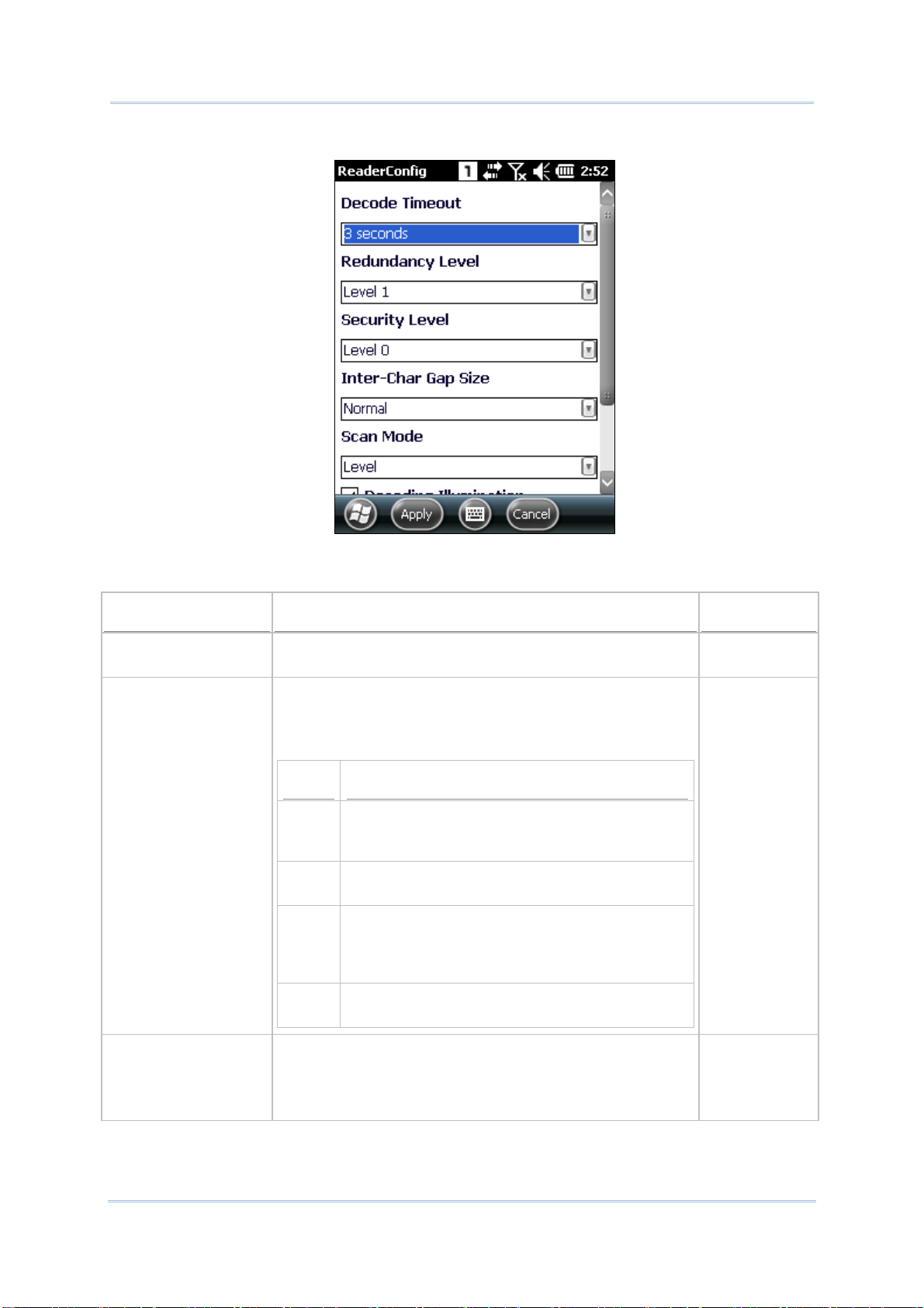
CP55 Mobile Computer
Scanner Preferences settings page opens.
Featured settings are different for each type of reader:
Reference Manual
CCD READER SETTINGS
Setting Description Default
Decode Timeout Sets the maximum time (configurable from 1 to 9 sec) for
the decoding process during a scan attempt.
Redundancy Level Sets how many successful readings should be done before
linear barcodes such as Codabar, MSI, and Interleaved 2 of
5 can be decoded. Levels 1 to 4 available.
The readings needed for each level are as follows:
3 sec
Level 1
Level Description
1 The following barcodes must be successfully
read twice before being decoded: Codabar, MSI,
Industrial 25 (Discrete 25), Interleaved 25.
2 All barcodes must be successfully read twice
before being decoded.
3 All barcodes must be successfully read twice
before being decoded, except for the following
which must be read three times: MSI, Industrial
25 (Discrete 25), Interleaved 25.
4 All barcodes must be successfully read three
Scan Mode Sets the reader’s scanning behavior.
times before being decoded.
Level
“Continuous” to decode the same barcode repeatedly or
decode different barcodes in a continuous motion.
“Level” for scanning by pressing the scan trigger.
52
Page 69

Chapter 2 Data Capture
Timeout Between
Symbols
Sets the time for the barcode reader to resurrect its ability to
once more decode a barcode it just decoded.
1 sec
Only applied in Continuous mode
1D (LASER) READER SETTINGS
Setting Description Default
Decode Timeout Sets the maximum time for the decoding process during a
scan. Configurable between 1 sec to 9 sec.
Redundancy Level Sets how many successful readings should be done before
linear barcodes such as Codabar, MSI, and Interleaved 2 of
5 can be decoded. Levels 1 to 4 available.
The readings needed for each level are as follows:
Level Description
1 The following barcodes must be successfully
read twice before being decoded: Codabar,
MSI, Industrial 25 (Discrete 25), Interleaved
25.
2 All barcodes must be successfully read twice
before being decoded.
3 sec
Level 1
3 All barcodes must be successfully read twice
before being decoded, except for the following
which must be read three times: MSI, Industrial
25 (Discrete 25), Interleaved 25.
4 All barcodes must be successfully read three
Scan Angle Sets the scan angle for laser scan engine. Options to
choose between are Wide Angle and Narrow Angle.
Scan Mode Sets the reader’s scanning behavior.
times before being decoded.
Continuous: Decode the same barcode repeatedly or
decode different barcodes in a continuous motion.
Level: Scanning by pressing the scan trigger.
Timeout Between
Symbols
Sets the time for the barcode reader to resurrect its ability
to once more decode a barcode it just decoded.
Only applied in Continuous mode
Wide Angle
Level
1 sec
53
Page 70

CP55 Mobile Computer
Reference Manual
2D IMAGER SETTINGS
Setting Description Default
Decode Timeout Sets the maximum time for the decoding process during a
scan. Configurable between 1 sec to 9 sec.
Redundancy Level Sets how many successful readings should be done before
linear barcodes such as Codabar, MSI, and Interleaved 2 of
5 can be decoded. Levels 1 to 4 available.
Security Level Sets the security level to ensure decoding accuracy
considering the printed quality of barcodes such as Code
128, Code 93, and UPC/EAN. The higher the level is, the
more security is ensured. Options are:
Level Description
0 With this default, the scan engine is aggressive
enough to decode most “in-spec” barcodes.
1 Select this level if misdecodes have occurred. It
fixes most misdecodes.
2 Select this level if Level 1 should fail to
eliminate misdecodes.
3 Select this level if Security Level 2 should fail to
prevent misdecodes. However, as this level
actually impairs the decoding ability of the
decoder, a safer solution would be to improve
Inter-Char Gap Size Sets the intercharacter gap size for Code 39 and Codabar.
Switch between Normal and Large.
the quality of the bar codes to read.
3 sec.
Level 1
Level 0
Normal
Scan Mode Sets the reader’s scanning behavior. Options available are
Level, Presentation Mode and Auto Aim.
Level
Level: Decoding process is activated by trigger event
and continues until trigger event ends, a valid decode
happens or decode session time-out is reached.
Presentation Mode: The imager engine attempts to
decode when an object appears in its field of view.
Sleeping state is not entered when this mode is
activated.
Auto Aim: Red aiming pattern is turned on when the
imager engine detects motion. A trigger event will then
activate decoding. If 2 seconds go by without any
activity, the aiming pattern goes off.
Decoding Illumination Enables an LED light beam to aid barcode reading. Selected
(Enabled)
Decode Aiming
Pattern
Picklist Mode When selected, only barcodes aligned at the crosshair of
Display Mode Enable improved performance for reading barcodes on
Projects a crosshair at the center of the laser light beam to
facilitate barcode reading.
the laser light beam will be decoded.
electronic displays and mobile phones.
Selected
(Enabled)
Deselected
(Disabled)
Deselected
(Disabled)
54
Page 71

Chapter 2 Data Capture
DATA OUTPUT
Data Output allows users to set the way to output decoded data.
To open Data Output settings page:
1) Open Reader Config as described in
Reader Config main menu opens.
2) Tap the arrow next to Data Output.
Data Output settings page opens.
Launch Reader Config.
Data Output settings
WHERE TO OUTPUT
Keyboard Emulation setting controls where the decoded data is to be output.
Setting
Keyboard Emulation Treats decoded data as typed text and outputs it to the active
Descriptions Default
application locally on the mobile computer or remotely on a
computer. Options are:
Disable – Disables Keyboard emulation whereby decoded
data won’t be output.
Input on local machine – Passes decoded data locally to the
active application on the mobile computer. Simply run an
application such as Wordpad to collect decoded data.
Input on remote PC – Passes decoded data to the active
application on the remote computer connected. Set up a
remote PC connection to collect data. (Note this option is
unable to pass double-byte characters such as Big-5 or
Unicode characters.)
Input on
local
machine
55
Page 72

CP55 Mobile Computer
Reference Manual
HOW TO OUTPUT
After the output destination is set, configure how to output decoded data, i.e. the “format”
to present decoded data.
Setting
Auto Enter Adds an ENTER character before or after each scanning act.
Description Default
Decoded
This function saves the trouble pressing [Enter] key to
confirm each scan. Options are:
data +
Enter
Disable
Decoded data + Enter
Enter + Decoded data
Auto Enter character Adds a key code before or after the decoded data. This
setting is available only when [Auto Enter] is enabled.
Options are:
Carriage
Return
None
Carriage Return
Tab
Space
Comma
Semicolon
Display Code Type Prefixes the output data with code type information. Deselected
(Disabled)
Show Code Length Suffixes the output data with code length information. Deselected
(Disabled)
Prefix Affixes 0 to 10 characters to the left of the output data. Tap
the keyboard icon
character table for entering the prefix.
next to the input field to open a
--
Prefixes containing invisible characters are supported.
Suffix Affixes 0 to 10 characters to the right of the output data. Tap
the keyboard icon
character table for entering the suffix.
next to the input field to open a
--
Suffixes containing invisible characters are supported.
Field delimiter Sets the delimiter to separate the output barcode data to the
following pieces: code type, decoded barcode data, and code
length (if applicable). Options are:
Comma
Comma
Semicolon
ENABLE READER
Features a checkbox to enable or disable reader scanning ability. When enabled, light beam
will be sent out each time the trigger (scan key) is pressed.
Full stop
56
Page 73

Chapter 2 Data Capture
NOTIFICATION SETTINGS
Notification Settings enables audible, visible and tactile feedback for scanning good read,
which helps notify the user of a successful decoding.
To open Notification Settings page:
1) Open Reader Config as described in
Launch Reader Config.
Reader Config main menu opens.
2) Tap the arrow next to Notification Settings.
Notification Settings page opens.
Notification Settings
Setting
LED
Vibrator
Beeper
Enable LED when
good read
Vibrator when good
read
Beep when good
read
Description Default
Selects to enable/disable LED light (left) for
scanning good read. See
Enables/disables tactile feedback (vibration) for
good read and sets the vibration duration.
Sets the beeper sound for scanning good read.
Users can choose to mute the beeper sound, or
configure the beeper between sounds 1 to 9.
Status LED for details.
Deselected
(Disabled)
0 second
Sound 1
57
Page 74

CP55 Mobile Computer
Reference Manual
2.1.3. SYMBOLOGY
Symbology section sets the symbologies to read, and also enables/disables some
feature(s) for a symbology to read, such as:
Customize and transmit start/stop characters
Verify/transmit check digits
Enable/disable addon digits
Convert to another symbology
Transmit symbology ID
Symbology
To open Symbology settings page:
1) Open Reader Config as described in
Reader Config main menu opens.
2) Tap the arrow next to 1D Symbologies (or 2D Symbologies in the case of a 2D
imager).
Launch Reader Config.
58
Page 75

T
Chapter 2 Data Capture
Symbology settings page opens listing all symbologies which can be decoded.
1D Symbologies 2D Symbologies
ENABLE/DISABLE SYMBOLOGY
The icon in the Enable column indicates whether the specific symbology is enabled. A
check
indicates decoding of the symbology is disabled. Tap the icon to switch between
enable/disable modes.
indicates that decoding of the symbology is enabled, while a short bar
Tap to disable symbology
ap to enable symbology
59
Page 76

CP55 Mobile Computer
Reference Manual
SYMBOLOGY SETTINGS
Tap the arrow next to each symbology checkbox to access detailed settings for that
symbology.
60
Page 77
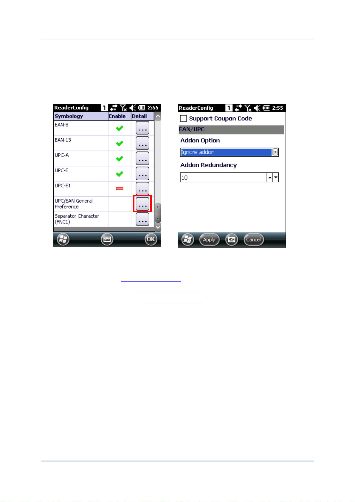
Chapter 2 Data Capture
GENERAL PREFERENCES
For certain symbologies, common settings are grouped together and displayed in a detailed
settings page for that barcode family. To open the general settings page for a set of
symbologies, tap the arrow next to General Preference.
General settings are provided for Composite Code, Postal Code, and UPC/EAN families.
For details about the featured settings:
See Appendix II: CCD
See Appendix III: 1D Laser
See Appendix IV: 2D Imager
Symbology Settings.
Symbology Settings.
Symbology Settings.
61
Page 78

CP55 Mobile Computer
Reference Manual
2.1.4. MISCELLANEOUS
This section allows enabling code ID transmission for easy identification of the scanned
barcode.
Miscellaneous
Setting
Transmit AIM Code ID Sets whether to include AIM code ID character in the
Description Default
decoded data. For AIM code ID, see the following:
Appendix II: CCD Symbology Settings
Appendix III: 1D Laser Symbology Settings
Appendix III: 2D Imager Symbology Settings
Deselected
(Disabled)
62
Page 79

Chapter 2 Data Capture
2.1.5. READER CONFIG OPTION MENU
Reader Config provides an option menu which is accessible on the menu bar of the main
settings page. This menu allows you to import/export all settings in a re-usable format,
reset all settings back to factory default, view copyright and version information, and exit
the application.
63
Page 80

CP55 Mobile Computer
Reference Manual
RESET TO FACTORY DEFAULT
This function restores all settings in the Reader Config application to default.
To enable Factory Reset:
1) Open Reader Config as described in
Launch Reader Config.
Reader Config main view opens.
2) Tap Menu button on the menu bar to open the option menu.
3) Tap Reset to Factory default.
4) A warning dialog appears confirming whether to restore all application settings back to
default. Tap Yes to reset or No to close the dialog.
A warning dialog pops up
to confirm if reset should
be performed
64
Page 81

Chapter 2 Data Capture
IMPORT AND EXPORT
Reader Config supports saving the settings and exporting them as an .xml file.
Previously exported symbology and scanner settings can be imported again on the mobile
computer. This can also be used to implement identical Reader Config settings on two or
more devices.
To import settings:
1) Open Reader Config as described in
Launch Reader Config.
Reader Config main view opens.
2) Tap Menu button on the menu bar to open the option menu.
3) Tap Import in the option menu.
A page opens allowing you to select a previously saved profile.
“All Folders” refers to all folders under
My Device\My Documents
directory
Select a previously
exported profile
4) Select the profile you would like to apply and tap OK. In a few seconds a prompt will
appear on the mobile computer to indicate settings have been imported successfully.
65
Page 82

CP55 Mobile Computer
To export settings:
Reference Manual
1) Open Reader Config as described in
Reader Config main view opens.
2) Tap Menu button on the menu bar to open the option menu.
3) Tap Export.
An export page opens allowing you to enter and select information about the profile to
be saved.
Launch Reader Config.
Enter information about
the profile to save
4) Enter file name, storage folder and location. Tap OK to export. A prompt will appear
on-screen to notify that settings have been exported.
66
Page 83

Chapter 2 Data Capture
ABOUT
Tap About in the Reader Config option menu to display software version and copyright
information.
Information about the
software
67
Page 84

CP55 Mobile Computer
Reference Manual
2.1.6. READ PRINTED BARCODES
Aside from output to destinations as per Keyboard Emulation settings, Reader Config
provides a Scan Test feature for quick viewing of decoded data.
To perform test scanning of barcodes:
1) Open Reader Config as described in
2) Tap Scan Test on the menu bar.
A Test Scan Form opens for displaying the scanned data.
3) Aim the scanning window at the printed barcode to read and press the scan key (or any
of the two side triggers).
Launch Reader Config.
The scanning light beams to read the printed barcodes.
The scanning light goes off once data is decoded, or decoding timeout is reached.
Figure 15: Read printed barcodes
68
Page 85

Chapter 2 Data Capture
The decoded data will appear on the page. When finished viewing, tap OK on the softkey
bar to leave the test scan page.
Tap to exit the test scan
page
To display more information such as barcode type and length, configure the reader as in
Data Output.
You may also configure the reader module before starting to collect data.
TEST SCAN MENU
Tap the Menu button to save the decoded data as a .txt file, clear all data shown on the
screen, or exit the Test Scan page.
Tap to save the decoded
data as a .txt file
Tap to clear all the
data on-screen
Tap to exit Test Scan
69
Page 86

CP55 Mobile Computer
Reference Manual
2.2. USE HF RFID CONFIGURATION
2.2.1. LAUNCH HF RFID CONFIGURATION
If the mobile computer is equipped with an RFID reader, you may use HF RFID
Configuration to configure the RFID reader and test scan RFID tags.
1) Tap Start | Settings | System | HF RFID Configuration.
HF RFID Configuration main view opens showing two sections, RFID Test and
General Settings.
Open Option
Menu
.
Exit HF RFID
Configuration
70
Page 87

Chapter 2 Data Capture
2.2.2. GENERAL SETTINGS
General Settings can set the data output format, notification of successful reading/writing
of RFID tags, and check or change ISO14443A Key A and Key B values. The following items
are available.
Enable RFID Reader (Enabled by default)
Data Output
Notification Settings
ISO14443A Login Key
ISO14443A Change Key
DATA OUTPUT
Data Output chooses a location to export the decoded data, and the output format.
To open Data Output settings page:
1) Launch the RFID reader as described in
2) Tap the green arrow next to Data Output.
Launch HF RFID Configuration.
71
Page 88

CP55 Mobile Computer
Reference Manual
Setting Description Default
Keyboard
Emulation
Treats decoded data as typed text and outputs it to the active
application locally on the mobile computer or remotely on a
connected computer. Options are:
None: Disables Keyboard emulation whereby decoded data
won’t be output.
Input on local machine: Passes decoded data to the active
application on the mobile computer (for instance, Wordpad).
Input on remote PC: Passes decoded data to the active
application on the remote computer connected. (Note this
option is unable to pass double-byte characters such as Big-5
or Unicode characters.)
Auto Enter Adds an Enter character before or after each scanning act. This
function saves the trouble pressing [Enter] key to confirm each
scan. Options are:
Disable
Decoded data + Enter
Enter + Decoded data
Auto Enter
Char
Adds a key code before or after the decoded data. This setting is
available only when Auto Enter is enabled. Options are:
None
Carriage return
Input on local
machine
Scan + Enter
Char
Carriage
Return
Tab
Space
Comma
Semicolon
Prefix String Affixes 0 to 10 characters to the left of the output data. Tap the
keypad icon to open a table for entering invisible characters.
Suffix String Affixes 0 to 10 characters to the right of the output data. Tap the
keypad icon to open a table for entering invisible characters.
Display the UID Outputs the UID of the RFID tag to read. Selected
Display the
user data
Start byte Defines the position to start reading/writing data. Available for
Data length Sets how many bytes of data to collect. Available for setting
Field delimiter Sets the delimiter to separate the output RFID data to the following
Outputs the user data of the RFID tag to read. Deselected
setting between -1 to 64. See Appendix V:
between 1 to 128.
pieces: UID and user data (if applicable). Options are:
RFID Tag Default .
NULL
NULL
(Enabled)
(Disabled)
-1 (default
block, byte 0)
10
Comma
Comma
Semicolon
Full stop
72
Page 89
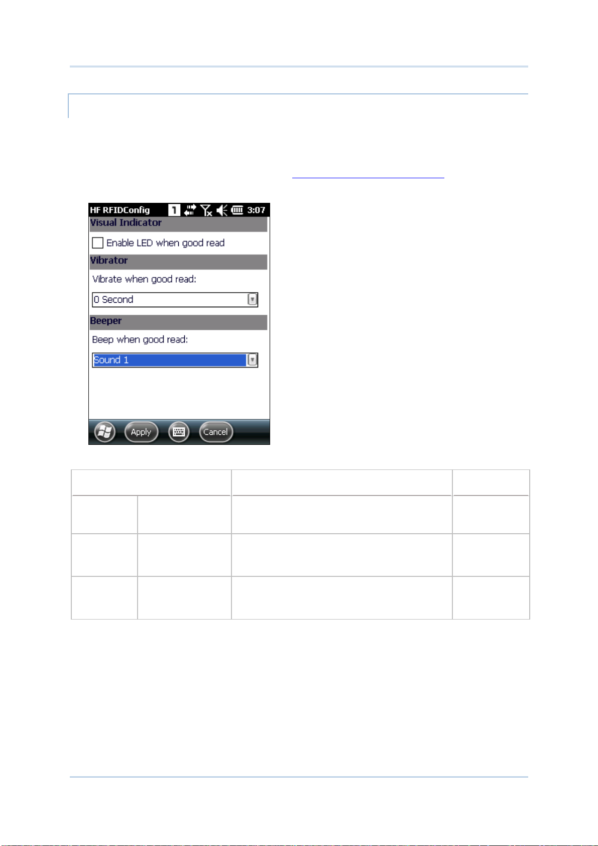
Chapter 2 Data Capture
NOTIFICATION SETTINGS
Notification Settings control if a successful decoding is made recognizable through
audible, visible and/or tactile feedback.
To open Notification Settings page:
1) Launch the RFID reader as described in
Launch HF RFID Configuration.
2) Tap the green arrow next to Notification Settings.
Setting
Visual
Indicator
Vibrator Vibrate when good
Beeper Beep when good
Enable LED when
good read
read:
read:
Description Default
Enables/disables the speaker to sound for good
read. Sounds 1 to 9 are configurable.
Enables/disables tactile feedback (vibration) for
good read and sets its duration. Configurable
duration is 0 to 9 seconds.
Enables/disables speaker to sound for good
read. Either set the beeper to mute, or
configure between sounds 1 to 9.
Deselected
(= disabled)
0 (= disabled)
Sound 1
73
Page 90

CP55 Mobile Computer
Reference Manual
ISO14443A LOGIN KEY
Some RFID tags support authentication for security concerns, such as Mifare Standard
1K/4K and SLE66R35 tags. The security keys, Keys A and Key B, are two keys that enable
the RFID reader to access (read or write) data blocks on a Mifare tag. Enter the keys before
proceeding to
Read and Write RFID Tags.
1) Launch the RFID reader as described in
Launch HF RFID Configuration.
2) Tap the green arrow next to ISO14443A Login Key.
3) Select Key A or Key B in the drop-down box. The field below displays the key value.
Setting
Login Key Use the Login key drop-down box to select Key A or
Description Default
Key B, and enter its current value in the field below.
Keys A and B are what the RFID reader module
relies on to access (read or write) an RFID tag. By
default, both keys are a sequence of twelve “F”
characters, which is the factory default for Mifare
tags. If the login key has been changed, enter its
new value in the field below.
If necessary, modify the key values under
ISO14443A Change Key.
Key A and
FFFFFFFFFFFF
74
Page 91

Chapter 2 Data Capture
ISO14443A CHANGE KEY
You may change the Keys A and/or B used to access an RFID tag. To change the value of key
A or key B:
1) Launch the RFID reader as described in
Launch HF RFID Configuration.
2) Tap the green arrow next to ISO14443A Change Key.
3) Enter the original value of key A or key B, the new assigned value, and the sector to
implement the change.
4) Place the RFID tag in proximity to the mobile computer’s back cover, where the RFID
reader module is installed.
5) Tap Apply in the upper left corner to implement the change.
Setting
Sector index Sets the sector to apply the change. 0
Origin key type Select to change either key A or key B. Key A
Origin key value Enter the original value of the key. FFFFFFFFFFFF
New key A Assign the new value of key A, which must be a hex
New key B Assign the new value of key B, which must be a hex
Description Default
FFFFFFFFFFFF
string of 12 bytes. The value of key A must be filled
whether or not you would like to change its value.
FFFFFFFFFFFF
string of 12 bytes. The value of key B must be filled
whether or not you would like to change its value.
75
Page 92

CP55 Mobile Computer
Reference Manual
2.2.3. HF RFIDCONFIG OPTION MENU
On the HF RFIDConfig main view is a menu button which allows you to import and export
the settings, reset all settings back to default, check software version and developer
information, or exit the application.
76
Page 93

Chapter 2 Data Capture
RESET TO FACTORY DEFAULT
This function restores all settings in HF RFIDConfiguration to default.
To reset the settings to default:
1) Launch the RFID reader as described in
Launch HF RFID Configuration.
2) Tap Menu button on the menu bar to open the option menu.
3) Tap Reset to Factory default.
A warning dialog appears confirming whether to restore all application settings back to
default. Tap Yes to reset or No to close the dialog.
A warning dialog pops up
to confirm if reset should
be performed
77
Page 94

CP55 Mobile Computer
Reference Manual
IMPORT AND EXPORT
HF RFID Configuration supports saving the settings and exporting them as an .xml file.
Previously exported symbology and scanner settings can be imported again on the mobile
computer. This can also be used to implement identical HF RFID Configuration settings
on two or more devices.
To import settings:
1) Launch the RFID reader as described in
2) Tap Menu button on the menu bar to open the option menu.
3) Tap Import in the option menu.
A page opens allowing you to select a previously saved profile.
Launch HF RFID Configuration.
Select a previously exported profile
4) Select the profile you would like to apply and tap OK. An alert sound will play to indicate
the settings have been imported successfully.
78
Page 95
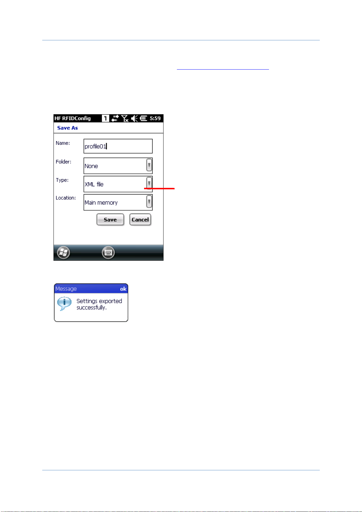
Chapter 2 Data Capture
To export settings:
1) Launch the RFID reader as described in
2) Tap Menu button on the menu bar to open the option menu.
3) Tap Export.
An export page opens allowing you to enter and select information about the profile to
be saved.
Launch HF RFID Configuration.
Enter a name for the
profile to save
4) Enter file name, storage folder and location. Tap OK to export. A prompt will appear
on-screen to notify that settings have been exported.
79
Page 96

CP55 Mobile Computer
Reference Manual
ABOUT
Tap About in the HF RFID Configuration option menu to display software version and
copyright information.
Information about the
software
80
Page 97

Chapter 2 Data Capture
2.2.4. READ AND WRIT E RFID TAGS
To read an RFID tag:
1) Adjust the RFID reader settings first. For instance, specify how many bytes you would
like to read from the tag, the start position to collect data, where and how to output data
Data Output. If security keys are needed to access the data on the RFID tag, specify
in
Key A and/or Key B in
2) Tap the green arrow next to Read / Write Block.
Read tab page opens with a blank test scan page to display the decoded data.
ISO14443A Login Key.
3) Place the RFID tag in proximity to the mobile computer’s back cover, where the RFID
reader module is installed.
4) Press the scan key (or side trigger) on the mobile computer. The RFID reader will scan
for RFID tags within reading range.
81
Page 98

CP55 Mobile Computer
Reference Manual
The decoded data will display in the test scan field below. Tap Back in the upper left
corner to leave the test scan page.
Set the block to
start reading data
from
Shows the
decoded data
Tap to leave the
test scan page
Note: Refer to the specifications of the RFID tag to read for its memory organization.
82
Page 99

Chapter 2 Data Capture
To write data into an RFID tag:
1) Tap Write tab page.
2) Input the data you would like to write in the blank field below.
3) Press the scan key (or side trigger) on the mobile computer.
If data failed to write into the RFID tag, an error message will display in the Response
field below.
Set the block to
Check to write
the data in
hexadecimal
format
write data to
Input the data to
write to the RFID
tag
If failure occurs
during data writing,
an error message will
be displayed in the
Response field
Tap to leave the
test scan page
Note:
(1) Generally the readable RFID data lies in user block. If the data to collect confides in a
non-user block such as the lock block, select Display hex values lest the data to collect
involves any invisible character.
(2) Different RFID tags may have different default blocks (also “pages”), and different
amount of bytes and number of blocks. The data written will be truncated to fit inside
the blocks of the targeted RFID tag. Therefore part of the data may be discarded when
it comes to the end of a block. Refer to
RFID Tag Default .
(3) You may set the start byte to read/write data and the length of the data to read/write on
the
Data Output page.
83
Page 100

CP55 Mobile Computer
Reference Manual
84
 Loading...