

Page 1
Windows Embedded Handheld 6.5
CP50/CP50 G
Version 1.00
Page 2

COPYRIGHT
PREFACE
Copyright © 2012 CIPHERLAB CO., LTD.
All rights reserved
The information contained in this document, including all pictures, illustrations and software,
is the proprietary information of CIPHERLAB CO., LTD. and its respective legal owners; it is
protected by copyright laws and international copyright treaties, as well as other intellectual
property laws and treaties, with all rights reserved.
In no event and by no part shall this document be reproduced, stored in a retrieval system,
or transmitted in any form or by any means including but not limited to electronic,
mechanical, photocopying, and recording without the prior written consent of CIPHERLAB
CO., LTD. Any reverse engineering of software is also prohibited.
DISCLAIMER
The information herein is subject to change without notice. The information and the
intellectual property herein are confidential between you and CIPHERLAB CO., LTD. and
remain the exclusive property of CIPHERLAB CO., LTD. and its respective legal owners.
Should you find any problems in this document, please report them to CIPHERLAB in writing.
CIPHERLAB does not warrant this document is error-free.
TRADEMARK RECOGNITION
CipherLab logo is a registered trademark of CIPHERLAB CO., LTD. Windows Embedded
Handheld is a registered trademark or trademark of Microsoft Corporation in the United
States and/or other countries. All other brands, products and services, and trademark
names are the property of their registered owners. The editorial use of these names is for
identification as well as to the benefit of the owners, with no intention of infringement.
CONTACT
For product consultancy and technical support, please contact CIPHERLAB’s sales
representative in your local area. You may also visit CIPHERLAB web site for more
information.
CIPHERLAB CO., LTD.
Website: http://www.cipherlab.com
Page 3

SAFETY NOTICES
FOR HAND-HELD PRODUCT WITH RF FUNCTIONS
CP50/CP50 G serial handheld equipment uses wireless radios that have been designed and
manufactured to meet safety requirements for limiting exposure to radio waves. When used
in accordance with the instructions set forth in this manual, the equipment has been
independently verified to not exceed the emission limits for safe exposure to radio
frequency (RF) energy as specified by EN50360 of EEC.
These limits are part of comprehensive guidelines and establish permitted levels of RF
energy for the general population. The guidelines are based on standards that were
developed by independent scientific organization through periodic and thorough evaluation
of scientific studies. The standards include a substantial safety margin designed to assure
the safety of all persons, regardless of age and health.
The exposure standard for all wireless devices employs a unit of measurement known as the
Specific Absorption Rate, or SAR; the SAR limit set by CE is 2.0W/Kg.
For trunk, the SAR value of CP50/CP50 G serial handheld is:
EEC: MAX 0.335W/Kg (CP50 G), 0.013 (CP50)
FOR PRODUCT WITH LASER
CAUTION
This laser component emits FDA / IEC Class 2 laser light at the exit port. Do not
stare into beam.
Page 4

SAFETY PRECAUTIONS
RISK OF EXPLOSION IF BATTERY IS REPLACED BY AN INCORRECT TYPE. DISPOSE
OF USED BATTERIES ACCORDING TO THE INSTRUCTIONS.
The use of any batteries or charging devices, which are not originally sold or
manufactured by CipherLab, will void your warranty and may cause damage to human
body or the product itself.
DO NOT disassemble, incinerate or short circuit the battery.
DO NOT expose the scanner or the battery to any flammable sources.
For green-environment issue, it's important that batteries should be recycled in a proper
way.
Under no circumstances, internal components are self-serviceable.
The charging and communication cradle uses an AC power adapter. A socket outlet shall
be installed near the equipment and shall be easily accessible. Make sure there is stable
power supply for the mobile computer or its peripherals to operate properly.
CARE & MAINTENANCE
This mobile computer is intended for industrial use. The mobile computer is rated IP65,
however, the mobile computer can get damaged when being exposed to extreme
temperatures or soaked wet.
When the enclosure of the mobile computer gets dirty, use a clean and wet cloth to wipe
off the dust. DO NOT use/mix any bleach or cleaner. Always keep the LCD dry.
For a liquid crystal display (LCD) or touchscreen, use a clean, non-abrasive, lint-free
cloth to wipe dust off the screen. DO NOT contact the surface with any pointed or sharp
object.
If you want to put away the mobile computer for a period of time, download the
collected data to a host computer, and then take out the battery pack. Store the mobile
computer and battery pack separately.
When the mobile computer resumes its work, it takes some time for the main and
backup batteries to become fully charged.
If you shall find the mobile computer malfunctioning, write down the specific scenario
and consult the sales representative in your local area.
Page 5

DECLARATION OF CONFORMITY - EU
This device complies with the essential requirements of R&TTE Directive 1999/5/EC. The
following test methods have been applied in order to prove presumption of conformity with
the essential requirements of R&TTE Directive 1999/5/EC:
EN 60950-1: 2006 + A11: 2009
Safety of Information Technology Equipment
EN 300 330-1 V1.7.1: 2006
Electromagnetic compatibility and Radio spectrum Matters (ERM); Short Range Devices
(SRD); Radio equipment in the frequency range 9 kHz to 25 MHz and inductive loop systems
in the frequency range 9 kHz to 30 MHz; Part 1: Technical characteristics and test methods.
EN 300 330-2 V1.5.1: 2006
Electromagnetic compatibility and Radio spectrum Matters (ERM); Short Range Devices
(SRD); Radio equipment in the frequency range 9 kHz to 25 MHz and inductive loop systems
in the frequency range 9 kHz to 30 MHz; Part 2: Harmonized EN under article 3.2 of the
R&TTE Directive.
EN 300 440-1 V1.6.1: 2010
Electromagnetic compatibility and Radio spectrum Matters (ERM); Short range devices;
Radio equipment to be used in the 1 GHz to 40 GHz frequency range; Part1: Technical
characteristics and test methods.
EN 300 440-2 V1.4.1: 2010
Electromagnetic compatibility and Radio spectrum Matters (ERM); Short range devices;
Radio equipment to be used in the 1 GHz to 40 GHz frequency range; Part 2: Harmonized EN
under article 3.2 of R&TTE Directive.
EN 300 328-V1.7.1: 2006
Electromagnetic compatibility and Radio spectrum Matters (ERM); Wideband Transmission
systems; Data transmission equipment operating in the 2,4 GHz ISM band and using spread
spectrum modulation techniques; Harmonized EN covering essential requirements under
article 3.2 of the R&TTE Directive.
EN 301 908-1 V5.2.1: 2011
Electromagnetic compatibility and Radio spectrum Matters (ERM); Base Stations (BS),
Repeaters and User Equipment (UE) for IMT-2000 Third-Generation cellular networks; Part
1: Harmonized EN for IMT-2000, introduction and common requirements, covering
essential requirements of article 3.2 of the R&TTE Directive.
EN 301 511-V9.0.2: 2003
Global System for Mobile communications (GSM); Harmonized standard for mobile stations
in the GSM 900 and DCS 1800 bands covering essential requirements under article 3.2 of
the R&TTE directive (1999/5/EC).
EN 301 489-1 V1.8.1: 2008
Electromagnetic compatibility and Radio Spectrum Matters (ERM); ElectroMagnetic
Compatibility (EMC) standard for radio equipment and services; Part 1: Common technical
requirements.
EN 301 489-3 V1.4.1 2002
Page 6

Electromagnetic compatibility and Radio Spectrum Matters (ERM); ElectroMagnetic
Compatibility (EMC) standard for radio equipment and services; Part 3: Specific conditions
for Short-Range Devices (SRD) operating on frequencies between 9 kHz and 40 GHz.
EN 301 489-7 V1.3.1: 2005
ElectroMagnetic compatibility and Radio spectrum Matters (ERM); ElectroMagnetic
Compatibility (EMC) standard for radio equipment ad services; Part 7: Specific conditions
for mobile and portable radio and ancillary equipment of digital cellular radio
telecommunications systems (GSM and DCS).
EN 301 489-17 V2.1.1 2009
Electromagnetic compatibility and Radio spectrum Matters (ERM); ElectroMagnetic
Compatibility (EMC) standard for radio equipment and services; Part 17: Specific conditions
for 2,4 GHz wideband transmission systems and 5 GHz high performance RLAN equipment.
EN 301 489-24 V1.5.1: 2010
Electromagnetic compatibility and Radio Spectrum Matters (ERM); ElectroMagnetic
Compatibility (EMC) standard for radio equipment and services; Part 24: Specific conditions
for IMT-2000 CDMA Direct Spread (UTRA) for Mobile and portable (UE) radio and ancillary
equipment.
Page 7

Version
Date
Notes
1.00
6th July 2012
Initial
RELEASE NOTES
Page 8

Page 9

CONTENTS
PREFACE .................................................................................................. II
Copyright .............................................................................................. ii
Disclaimer ............................................................................................. ii
Trademark Recognition .............................................................................. ii
Contact ................................................................................................ ii
Safety Notices ....................................................................................... iii
For Hand-held Product with RF Functions .................................................... iii
For Product with Laser .......................................................................... iii
Safety Precautions .................................................................................. iv
Care & Maintenance ................................................................................ iv
Declaration of Conformity - EU .................................................................... v
RELEASE NOTES ....................................................................................... VII
INTRODUCTION ......................................................................................... 1
About This Document ................................................................................ 1
Features ............................................................................................... 2
Inside the Package ................................................................................... 2
Accessories ............................................................................................ 2
USE MOBILE COMPUTER ............................................................................... 3
Take A Tour ........................................................................................... 4
Overview ........................................................................................... 4
Inside Battery Chamber .......................................................................... 5
Power On/Off ......................................................................................... 6
Notifications .......................................................................................... 7
Battery ................................................................................................. 9
Main Battery Setup ............................................................................... 9
Charge Batteries ................................................................................ 11
Monitor Battery Level .......................................................................... 14
Power Management ............................................................................. 17
Optimize Battery Life .......................................................................... 18
Text Input ........................................................................................... 19
Physical Keypad ................................................................................. 19
Onscreen Keyboard ............................................................................. 25
Handwriting Recognition ....................................................................... 30
Edit Text ......................................................................................... 32
Touch Control ....................................................................................... 34
Use Touchscreen ................................................................................ 34
Screen Orientation ............................................................................. 34
Adjust Backlight ................................................................................. 34
Calibration ....................................................................................... 35
Memory .............................................................................................. 37
Data Loss Caution ............................................................................... 37
Check Storage ................................................................................... 37
Insert SD Card ................................................................................... 39
Page 10

Direct Data Connection ............................................................................ 40
Use Cable ........................................................................................ 40
Use Cradle ....................................................................................... 40
Syncing Tools .................................................................................... 42
Sync Partnership ................................................................................ 42
1st USB Sync ...................................................................................... 43
Disconnect USB ActiveSync .................................................................... 45
ActiveSync Actions to Take .................................................................... 46
Charging & Communication Cradle .............................................................. 52
Use Converter ................................................................................... 52
Overview ......................................................................................... 53
Pistol Grip ........................................................................................... 54
Install Pistol Grip ............................................................................... 54
Scan ............................................................................................... 54
Uninstall Pistol Grip ............................................................................ 54
Audio Playback ..................................................................................... 55
Volume Control ................................................................................. 55
DATA CAPTURE ........................................................................................ 57
Launch Reader Module(s) ......................................................................... 58
Read Printed Barcodes & RFID Tags ............................................................. 59
Configure Reader(s) ................................................................................ 60
General tabbed page ........................................................................... 60
Symbologies Tabbed Page ..................................................................... 72
About tabbed page ............................................................................. 73
CAMERA ................................................................................................. 75
Launch Camera ..................................................................................... 76
Camera Screen .................................................................................. 76
Take Pictures ....................................................................................... 77
Camera Settings ................................................................................. 78
Launch Camcorder ................................................................................. 80
Camcorder Screen .............................................................................. 80
Shoot Videos ........................................................................................ 81
Camcorder Settings ............................................................................. 82
Pictures & Videos................................................................................... 84
OPERATING SYSTEM .................................................................................. 87
1st Startup ........................................................................................... 88
Today Screen ....................................................................................... 89
Customize Toady Screen ....................................................................... 91
Return to Today Screen ........................................................................ 91
Start Screen ......................................................................................... 92
Return to Start screen ......................................................................... 93
Title Bar .......................................................................................... 93
Manage Notifications ........................................................................... 95
Customize Start Screen ........................................................................ 96
Start Screen Icons .............................................................................. 99
Suspend & Reset Mobile Computer ............................................................. 102
Page 11

Suspend Mobile Computer .................................................................... 102
Wake up Mobile Computer ................................................................... 103
Reset Mobile Computer ....................................................................... 103
Set Screen Lock .................................................................................... 105
Unlock Screen .................................................................................. 105
Work with Menus .................................................................................. 106
Option MenuS ................................................................................... 106
Context MenuS ................................................................................. 107
Manage Applications .............................................................................. 108
Task Manager ................................................................................... 108
RADIOS ................................................................................................ 115
Access Cellular WAN .............................................................................. 116
Status Icons ..................................................................................... 116
Check What Network You’re Using .......................................................... 116
Enable/Disalbe Mobile Data .................................................................. 117
Use Only 2G Networks ......................................................................... 117
Cellular Data Setup ............................................................................ 118
Edit & Add Access Points ..................................................................... 119
USB Internet Sharing .......................................................................... 120
Use Wi-Fi ........................................................................................... 121
Status Icons ..................................................................................... 121
Enable/Disable Wi-Fi .......................................................................... 121
Wi-Fi Connection Setup ....................................................................... 122
Connect Another Wi-Fi network ............................................................. 126
Edit Wi-Fi Networks ........................................................................... 126
Forget Wi-Fi Netowrks ........................................................................ 126
Receive notifications of Available networks ............................................... 126
Add Wi-Fi Networks............................................................................ 127
Connect by Static IP ........................................................................... 128
Advanced Wi-Fi Settings ...................................................................... 128
Use Bluetooth ...................................................................................... 130
Status Icons ..................................................................................... 130
ChangE Bluetooth name ...................................................................... 130
Expose Mobile computer ...................................................................... 131
Turn on/off Bluetooth ........................................................................ 132
Pair & Connect Bluetooth devices ........................................................... 132
Disconnect Bluetooth Devices ................................................................ 134
Unpair Bluetooth Devices ..................................................................... 135
ReConnect Bluetooth devices ................................................................ 135
Edit Bluetooth Features to Use .............................................................. 135
Bluetooth File Exchange ...................................................................... 136
Bluetooth ActiveSync .......................................................................... 138
Bluetooth Internet Sharing ................................................................... 139
Bluetooth Pass-through Networking ......................................................... 140
Connect to Virtual Private Networks ........................................................... 142
VPN Connection Setup ........................................................................ 142
Connect VPN .................................................................................... 144
Disconnect VPN ................................................................................ 145
Edit a VPN ....................................................................................... 145
Page 12

Delete a VPN ................................................................................... 146
Install Secure Certificates ....................................................................... 147
Supported Certificate Formats............................................................... 147
View Secure Certificates...................................................................... 147
Install secure CertificateS .................................................................... 148
Location Discovery ................................................................................ 149
Launch GPS & AGPS ........................................................................... 149
Use GPS & AGPS ................................................................................ 150
Use External GPS Receiver with Bluetooth ................................................. 150
Use Secure Access Module ....................................................................... 158
Assemble SAM Card ............................................................................ 158
Collect Payments .............................................................................. 159
PHONE ................................................................................................ 161
About Phone ....................................................................................... 162
SIM Card ............................................................................................ 162
Assemble SIM Card ............................................................................. 162
Status Icons ........................................................................................ 163
Phone Ringtone & Vibrate ....................................................................... 164
Phone Ringtone ................................................................................ 165
Phone Vibrate .................................................................................. 166
Phone Ringer Volume.......................................................................... 166
Place & End Calls .................................................................................. 167
Open Phone ..................................................................................... 167
Call History ..................................................................................... 171
Speed Dial....................................................................................... 172
Back to Phone Application .................................................................... 173
Disable Phone Calls ............................................................................ 174
Answer or Decline Calls .......................................................................... 175
Manage Call History ............................................................................... 176
Open Call History .............................................................................. 176
Add A Caller to Contacts ...................................................................... 176
View Caller Screen............................................................................. 177
Take Other Actions to A Call Log Entry ..................................................... 178
Clear Call History .............................................................................. 178
Call Contacts ....................................................................................... 179
Launch Contacts ............................................................................... 179
Take Other Actions to A Contact Entry ..................................................... 179
Check Voicemails .................................................................................. 180
Options during A Call ............................................................................. 181
Adjust in-call volume .......................................................................... 181
Put A Call on/off Hold ........................................................................ 182
Mute/Unmute Microphone .................................................................... 182
Turn on/off Speakerphone ................................................................... 182
Add A Call ....................................................................................... 183
Other Options .................................................................................. 183
Manage Multiple Calls ......................................................................... 183
Switch between Two Callers ................................................................. 185
Switch between Bluetooth Headset and Speakerphone .................................. 186
Page 13

Make An Emergency Call ......................................................................... 187
MORE APPLICATIONS ............................................................................... 189
Backup Utility ...................................................................................... 190
Launch Backup Utility ......................................................................... 190
Registry Backup and Restoration ............................................................ 191
System Files Backup ........................................................................... 193
System Files Restoration ...................................................................... 196
Clone ............................................................................................ 198
Button Assignment ................................................................................ 199
Launch Button Assignment ................................................................... 199
Redefine ........................................................................................ 199
Recover Defaults ............................................................................... 201
GPS Viewer ......................................................................................... 202
Launch GPS Viewer ............................................................................ 202
View NMEA-based Data ........................................................................ 204
Signature Utility ................................................................................... 205
Launch Signature Utility ...................................................................... 205
Capture Signatures ............................................................................ 206
View OR Edit Existing Signatures ............................................................ 206
Preferences ..................................................................................... 207
MANAGE MOBILE COMPUTER ...................................................................... 209
Update O.S. Image ................................................................................ 210
USB Upgrade .................................................................................... 210
SD Card Auto Update .......................................................................... 212
SD Card Manual Update ....................................................................... 214
System Settings .................................................................................... 216
Connections Folder ............................................................................ 219
Personal Folder ................................................................................ 225
System Folder .................................................................................. 226
SPECIFICATIONS ..................................................................................... 231
Platform, Processor & Memory .................................................................. 231
Communications & Data Capture ............................................................... 231
Electrical Characteristics ........................................................................ 232
Physical Characteristics .......................................................................... 232
Environmental Characteristics .................................................................. 233
Programming Support ............................................................................. 233
Accessories ......................................................................................... 234
SCAN ENGINE SETTINGS ............................................................................ 235
Symbologies Supported ........................................................................... 236
RFID Tags Supported .............................................................................. 238
LASER (SE955) ....................................................................................... 239
Symbology Settings................................................................................ 239
Miscellaneous ................................................................................... 242
AIM Code ID – Code Characters .............................................................. 242
AIM Code ID – Modifier Characters ........................................................... 243
Page 14

2D IMAGER (SE4500DL) ............................................................................ 247
Symbology Settings................................................................................ 247
1D Symbologies ................................................................................. 247
2D Symbologies ................................................................................. 253
Miscellaneous ................................................................................... 255
HF RFID READER ..................................................................................... 257
RFID Tag Default Block ........................................................................... 257
PHYSICAL KEYPAD REFERENCE TABLE .......................................................... 259
Numeric Keypad ................................................................................... 259
Use Alpha (α), Shift () & Fn Keys .......................................................... 259
QWERTY Keypad ................................................................................... 261
Use Alpha (α), Shift () & fN kEYS .......................................................... 261
Page 15

INTRODUCTION
Thank you for choosing CipherLab products. CipherLab welcomes another Windows
Embedded by introducing CP50 Series Mobile Computer. Powered by Windows Embedded
Handheld 6.5, the mobile computer delivers better user experience and promises enterprise
mobile computing.
The mobile computer has transflective LCD to hold up the readability in a wide range of light
conditions, courtesy of the supplementary backlight enabled by a built-in ambient light
sensor. Also on board is a G-sensor to save power according to the mobile computer’s
motion and posture. G-sensor also enables screen orientation when the device poses
sideways or upright. Security Access Modules (SAM) on the other hand favors the mobile
computer with payment applications.
The series sports satisfactory data connections by integrating a communication port for
direct data exchange. For wireless data connections it hosts each Bluetooth and 802.11b/g
module while a 3.75G module is provided on option.
Due to the built-in GPS receiver, Assisted-GPS is possible if 3.75G data is available on the
mobile computer. AGPS accelerates positioning even without a clear view of the sky given
a location-aware application to work with.
Dedicated to data capture, the mobile computer has essential 1D (laser) reader or 2D
imager plus RFID scan engine. A high-specced 5 mega-pixel camera also comes inside to
take pictures and shoot videos to deliver better documentation for users.
Rated with IP65, the rugged CP50 is light-weighted and easy to cradle in your hand, and will
be your good help on field works.
ABOUT THIS DOCUMENT
This guide distills the information about CP50 Series Mobile Computer. Subjects discussed
include the mobile computer’s physical features, platform basics, software and applications,
and part of the accessories to boost the mobile computer’s performance.
We recommend that you keep one copy of this manual at hand for the quick reference for
necessary maintenance.
1
Page 16

CP50 Mobile Computer Reference Manual
FEATURES
Rugged yet smoothened outlined, with hand strap for secure hold
IP65-rated tough form to survive drop, shock, heat, cold, and impervious to
moisture/dust.
Windows Embedded Handheld 6.5 OS, 800 MHz SAMSUNG S3C6410 CPU
256MB SDRAM to run application programs
2GB NAND flash to store OS, applications, settings and so on.
Storage expansion: 256MB to 4GB MicroSD and 4GB to 32GB MicroSDHC.
OS upgradable with external SD card
Sunlight-readable screen to enhance the viewability of outdoor use.
Ambient light sensor to enable supplementary backlight for LCD and keypad.
G-sensor for power management and screen orientation.
2 symmetric side-triggers for ambidextrous scanning
Total data solution — supporting Bluetooth, 802.11b/g and HSPA+
Security Access Module for payment-related applications
Built-in GPS receiver to deliver location discovery
A-GPS and E911 (CP50 G only)
5 mega-pixel camera for taking pictures and shooting videos.
C++ and .Net programming support
INSIDE THE PACKAGE
The mobile computer ships with the following items. Save the box and packaging material
in case of future need to store or deliver the mobile computer.
Mobile Computer
Rechargeable Li-ion battery pack
Universal power adapter
USB Charging & Communication Cable
Stylus
Product CD
LCD protective film
Quick Start Guide
Hand strap
ACCESSORIES
Optional accessories to enhance the mobile computer’s performance:
Pistol Grip
USB Cable
Hand Strap
Belt Holster with Shoulder Strap
Protective Cover
Charging & Communication Cradle with a spare battery
Vehicle Mount
Vehicle Charger
4-slot Gang Charger
2
Page 17

IN THIS CHAPTER
Take A Tour ....................................................................... 4
Power On/Off ..................................................................... 6
Battery .............................................................................. 9
Text Input ....................................................................... 19
Touch Control .................................................................. 34
Memory ........................................................................... 37
Direct Data Connection ..................................................... 40
Charging & Communication Cradle ...................................... 52
Audio Playback ................................................................. 55
USE MOBILE COMPUTER
Before the mobile computer takes part in your work, get to know it first. This chapter combs
the basic features of the mobile computer including the power supply, memory, and the
units that bridge users with the mobile computer. This chapter helps you set the mobile
computer to work at the earliest.
3
Page 18
CP50 Mobile Computer Reference Manual
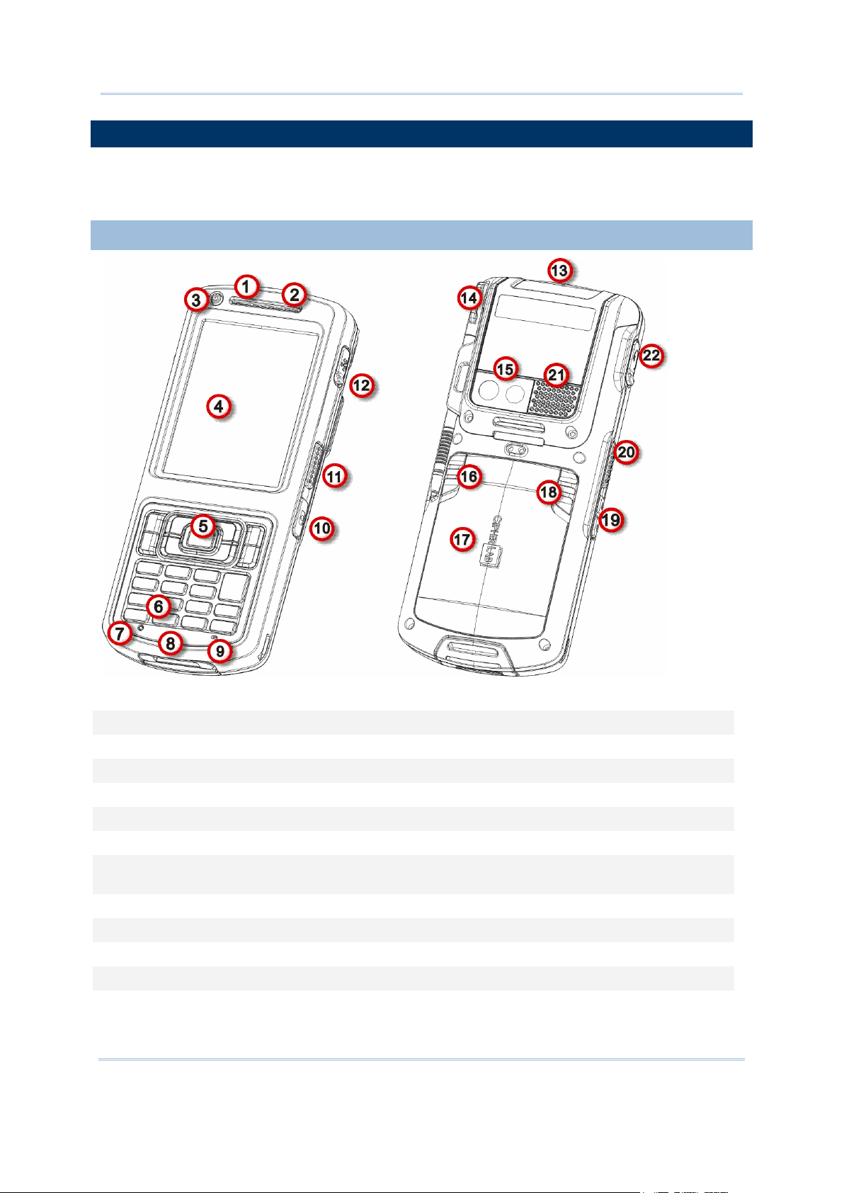
TAKE A TOUR
No.
Description
No.
Description
1
Status LED
2
Receiver
3
Power key
4
Touchscreen (QVGA)
5
Scan key
6
Keypad
7
Reset toggle (recessed in a cutout)
8
Direct charging- & communication-port
9
Microphone
10
Camera shutter button
11
Side-trigger (user definable)
12
External GPS antenna MMCX connector
(sealed with an attached & hinged rubber)
13
Scan window
14
Stylus
15
Camera
16
Battery lock
17
Battery door
18
Battery release (spring loaded)
19
Volume rocker
20
Side-trigger (user definable)
21
Speaker
22
Headset jack (sealed with an attached
and hinged rubber)
This section shows the major components on the mobile computer and inside battery
chamber. You will also learn how to power on/off the mobile computer and how the mobile
computer gives information about its status.
OVERVIEW
Figure 1: Overview
4
Page 19
Use Mobile Computer
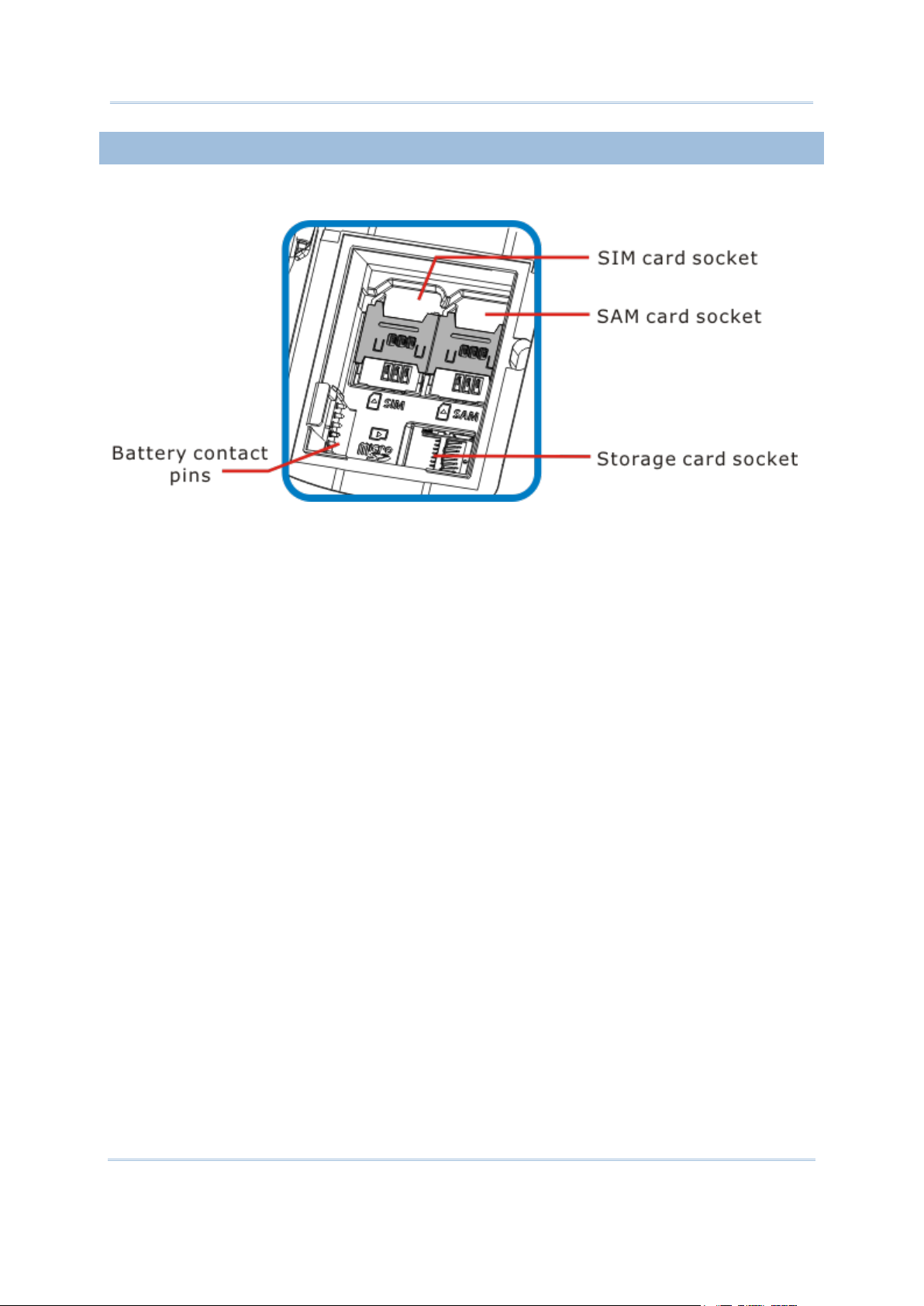
INSIDE BATTERY CHAMBER
Inside battery chamber are the sockets for SIM card, SAM card and storage card. Each is
equipped with a hinged cover.
Figure 2: Inside Battery Chamber
5
Page 20
CP50 Mobile Computer Reference Manual
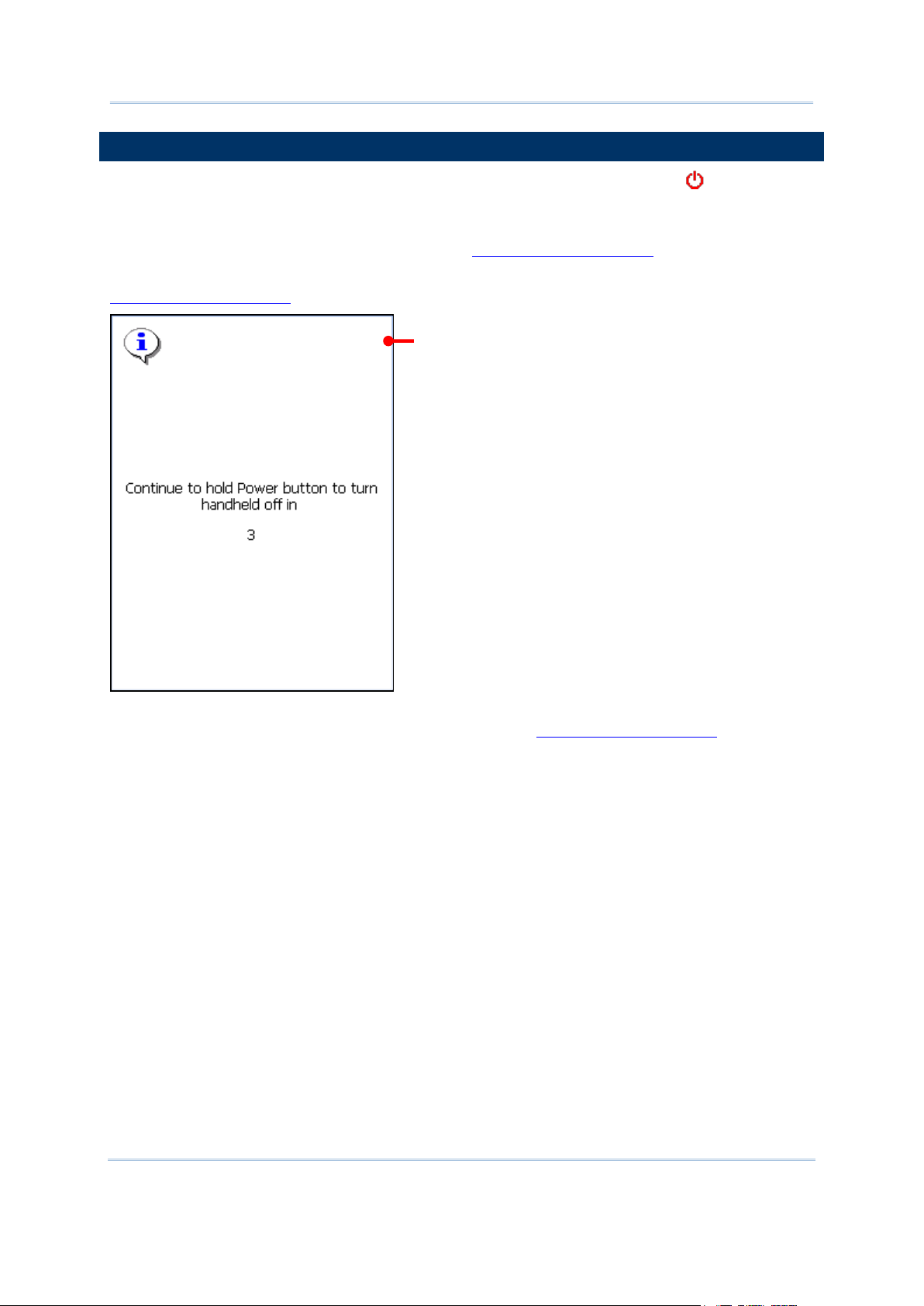
POWER ON/OFF
Powering-off screen
To power on/off the mobile computer, press and hold the Power button sitting above
the upper-left of touchscreen.
When powering off, the O.S. shows a screen that prompts to keep holding the Power button
until the mobile computer turns off. (See also Reset Mobile Computer.)
The power-off here is a “hard-off” by turning off the power supply to hardware. See also
Reset Mobile Computer.
This Power button is also a suspend button, press without holding it to suspend the mobile
computer when you are not actively using it. See also Reset Mobile Computer.
6
Page 21

Use Mobile Computer
NOTIFICATIONS
Matter
LED Color
Action
Description
Battery
Red & Green
Green on
Battery is fully charged.
Red. Slow blinking
Charging ongoing.
Red. Fast blinking
Charging error that may be caused by
temperature dropping below 0°C or
exceeding 40°C. See also Charge
Batteries.
Red. Fast blinking twice,
then off
Power-on error. The mobile computer
cannot power on when either of the
following happens:
Main battery drops under 7% and
over 1%.
Battery is absent but external power
is connected (by power adapter).
Battery is present (with power more
than 1%) but battery door isn’t in
place. See also Main Battery Setup.
Scanning
Good Read
Green
On for 2 seconds, then off
Enable/disable this notification by the
bundled utility ReaderConfigMobile.exe.
See the setting at Notifications.
Radios
Blue
Aptly blinking
Wi-Fi, Bluetooth or mobile data in use
The mobile computer features visible, audible, and tactile feedback to draw users’ prompt
awareness of the mobile computer’s contiguous events such as barcode reading,
wireless/mobile data connections, and battery charging.
STATUS LED
A triple-color LED light is recessed up front the mobile computer to communicate the mobile
computer’s statuses as below:
LED light is also programmable. See the API library that is readied for your reference.
SPEAKER
The mobile computer has a speaker on the rear for audio signaling, audio playback, and
phone ringtones.
The speaker sounds for system events, application warnings, onscreen items selections and
stroke on physical keypad as per Sounds & Notifications setting. In noisy environment, the
speaker remains efficacious with the help of a headset. To control sound volume, see
Volume Control.
The speaker also sounds for good barcode reading, which can be enabled/disabled by
CipherLab’s ReaderConfigMobile.exe. See Notifications for setting.
VIBRATOR
The mobile computer owes the tactile feedback to the vibrator built inside. The vibrator
applies vibration to users to alert them of the mobile computer’s status.
7
Page 22

CP50 Mobile Computer Reference Manual
Working based on user’s sense, the vibrator is particularly helpful when the mobile
computer is serving in noisy environment.
Same as the speaker and LED light, the vibrator works for good barcode reading.
CipherLab’s utility ReaderConfigMobile.exe enables users to turn the vibration on/off and
decides the duration. See Notifications.
The vibrator is also programmable. See the API library that is provided for your reference.
8
Page 23
Use Mobile Computer
BATTERY
The mobile computer is fed by two batteries, main battery pack and backup battery. Main
battery is removable and replaceable from battery chamber while backup battery is
mounted on the main board inside the mobile computer.
When the mobile computer ships, main battery isn’t installed but stored in a separate
package, which keeps it in good condition for future use.
MAIN BATTERY
Main battery is a 3.7V / 3300 mAh Li-ion battery pack to be put inside battery chamber.
Typically it takes about 4 hours to charge the main battery to full. The working time of the
mobile computer varies by its working states. Under normally operation, it works for up to
10 hours. An icon on Title Bar helps monitor main battery level. See Main Battery .
See also Main Battery Setup for the assembly.
BACKUP BATTERY
Backup battery settles on the main board inside the mobile computer. It is a 25 mAh
rechargeable Lithium type. When main battery is absent or depleted, backup battery takes
over to feed the mobile computer. Without main battery, a fully charged backup battery
retains the data in the DRAM and holds the system in suspension for 30 minutes.
Backup battery is rechargeable by the external power (through power adapter) or main
battery pack. It takes about 8 hours to charge it to full. An icon on the Title Bar makes
it observant that backup battery gets low. See also Backup Battery Level.
Note: To power on the mobile computer, the battery door must be installed in place. If not,
the status LED will blink red twice and go off to alert to failure to power on the mobile
computer. See also Status LED.
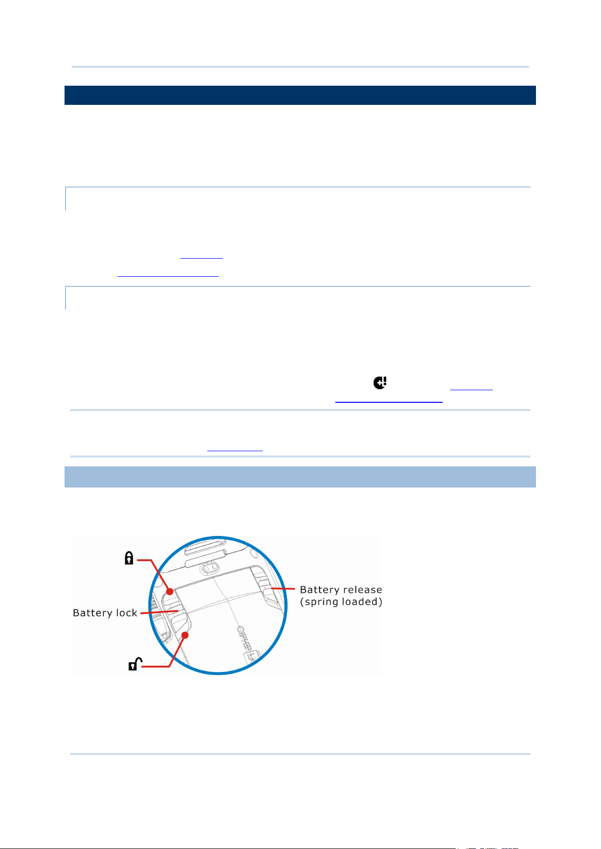
MAIN BATTERY SETUP
To secure main battery in place, the battery door is equipped with two latches, battery lock
and battery release. Battery lock needs to be manually closed while battery release is
spring-loaded and closes automatically.
Figure 3: Battery Door Latches
9
Page 24
CP50 Mobile Computer Reference Manual
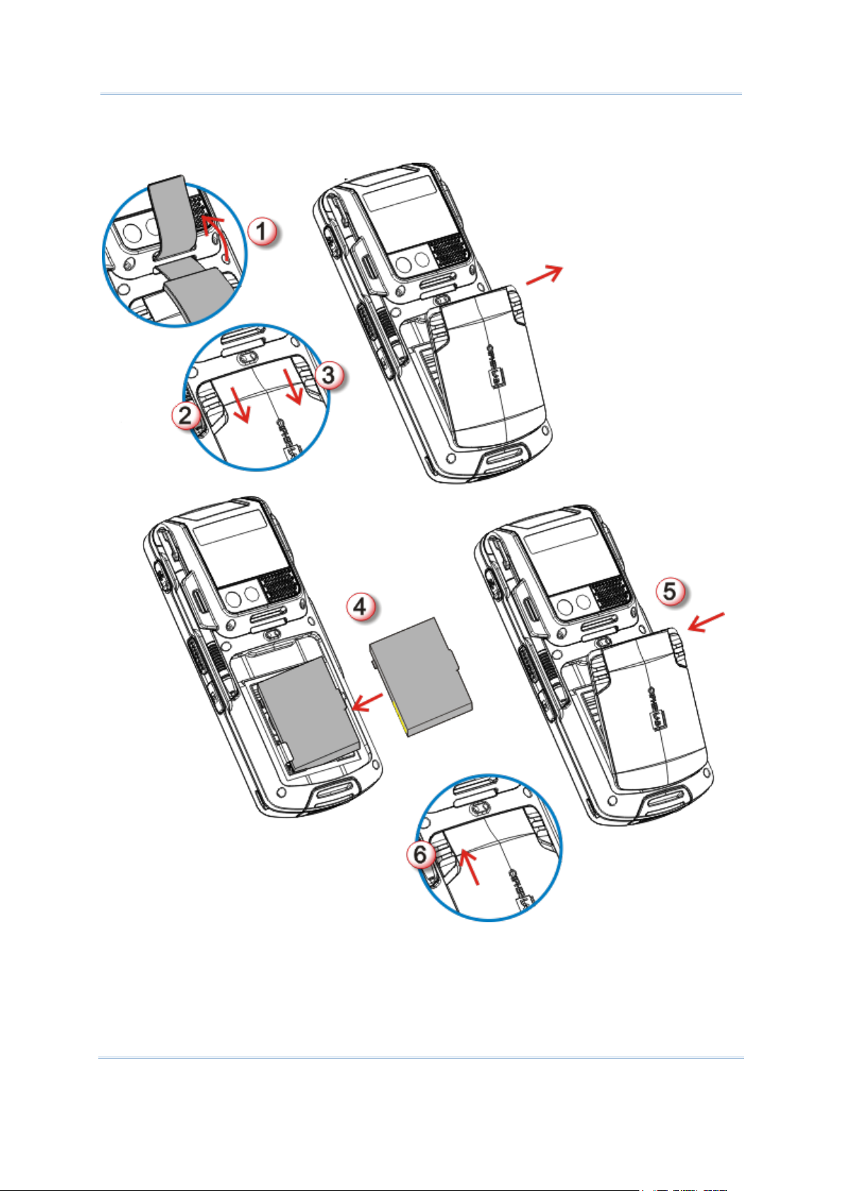
To install main battery pack, follow through the steps below by referencing to the
illustration:
Figure 4: Main Battery Setup
10
Page 25

Use Mobile Computer
1) Remove hand strap.
Charging Time
Main battery: It takes circa 4 hours to charge main battery to full (direct charging with power
adapter). The status LED above the touchscreen slowly blinks red during charging, and lights
green and stays on when fully charged.
Backup battery: Backup battery is rechargeable by both main battery and power adapter. It
takes about 8 hours to charge it to full. Besides it needs not to be fully charged for the mobile
computer to work.
Charging Temperature
It is recommended that batteries be charged at room temperature (18°C~25°C) for optimal
performance.
Charging stops when temperature drops below 0°C or exceeds 40°C.
Power Consumption
When all radios (802.11b/g, Bluetooth, mobile data (HSPA+), GPS) are active on battery power,
main battery drops substantially.
In order to prevent system from shutting down due to depleted main battery, we suggest that
you keep a fresh battery for replacement or have the mobile computer access the radios on
external power.
2) Push battery lock to unlock position.
3) Push back battery release, which is spring-loaded.
Battery door opens automatically. Detach battery door to reveal battery chamber.
4) Have main battery pack. Position and fit it into battery chamber by meeting its edge
connectors with the contact pins inside chamber.
5) Click battery door back in place.
6) Push battery lock to lock position.
Note: (1) Any improper handling may reduce battery life.
(2) When main battery level drops to low level, charge it ASAP or replace it with a
charged one.
(3) Always turn off the mobile computer to replace main battery pack.
CHARGE BATTERIES
Due to shipment, it is likely main battery and backup battery aren’t fully charged when you
receive the package. Before setting the mobile computer to work, charge main battery to
full by direct charging using power adapter (with the help of a USB Charging &
Communication Cable or Cradle).
Since main battery is the only source backup battery taps power from, be sure to install
main battery for the 1st charge so both main battery and backup battery get charged.
Some key facts about charging batteries:
The following guides how to charge batteries.
11
Page 26
CP50 Mobile Computer Reference Manual
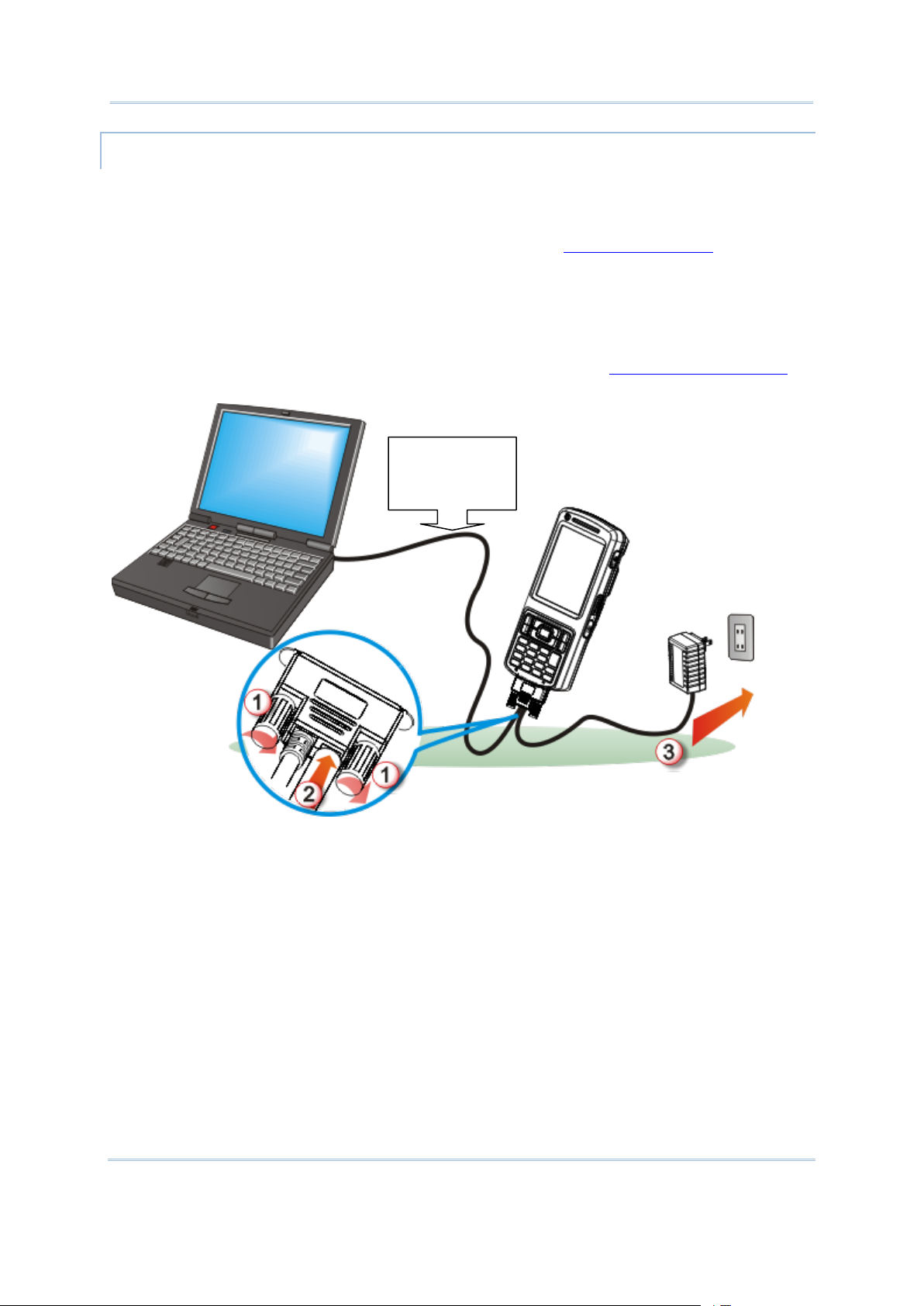
DIRECT CHARGING USING CABLE
When data
transmission is
required.
Direct charging the mobile computer relies on the USB Charging & Communication Cable
(hereinafter “USB cable”) included in the package. There is a power jack on the connector
of this USB cable to tap external power.
Before start charging, install main battery as described in Main Battery Setup. Then follow
through the steps below:
1) Lock up USB cable to the mobile computer.
2) Have the power adapter. Plug its power cord to the power jack on USB cable’s connector.
3) Connect power adapter’s wall-wart plug to a power outlet.
To output data to your PC or laptop, connect USB cable to it. See Direct Data Connection for
follow-ups.
Figure 5: Direct Charging Using Cable
12
Page 27
Use Mobile Computer
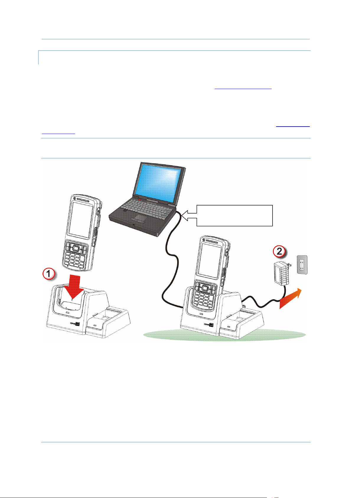
DIRECT CHARGING USING CRADLE
Only when data
transmission is required.
Direct cradle charging makes use of a Charging & Communication Cradle (hereinafter
“cradle”). Cradle is one of the accessories you can opt for.
Before start charging, install main battery as described in Main Battery Setup. Then follow
through the steps below:
1) Seat the mobile computer into cradle.
2) Connect cradle to an external power source using power adapter.
To output data to your PC or laptop, connect two devices with USB cable. See Direct Data
Connection for follow-ups.
Note: When the mobile computer is charged through cradle, and USB cable is also
connected for data, the power jack on USB cable’s connector is inefficacious.
Figure 6: Direct Charging Using Cradle
13
Page 28

CP50 Mobile Computer Reference Manual
MONITOR BATTERY LEVEL
Icon
Battery Status
Main battery is getting charged from external power.
Main battery reaches 80% to full.
Main battery partially drains between 60%-79%.
Main battery drops between 40%-59%.
Main battery drops between 20%-39%. O.S. prompts for recharge.
Main battery drops under 7%. Battery needs charging immediately.
Main battery is the only source that feeds the mobile computer to work. It also supplies the
backup battery on main board to hold the data stored in DRAM. Hence when main battery
gets low, recharge it or change it as soon as possible. But foremost, back up the important
data from time to time to protect your work.
MAIN BATTERY LEVEL
The O.S. features a few icons for user’s immediate awareness of main battery level. These
icons avail themselves of Title Bar to show. Title Bar settles at the top of almost every
screen.
STATUS ICONS
Main battery icons communicate the following statuses:
MORE CHARGE INFO
To know more about main battery level:
1) Tap Windows icon on Softkey bar or hit physical Windows key .
Start screen opens.
2) Tap Settings | System | Power .
Power application opens showing Battery tabbed page. The page shows a horizontal bar
to enable user’s quick grasp of battery’s contiguous power amount with a glance.
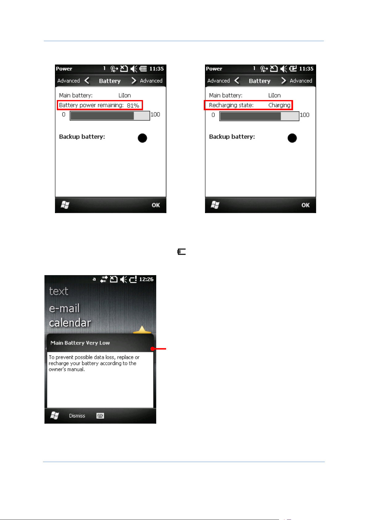
When main battery isn’t being charged, the page auto-rates the remaining power with
percentage. However when main battery is being charged, the page doesn’t show
percentage-amount but “charging” state only. However the horizontal graphic bar
encapsulates the remaining power amount whether main battery is being charged or
not.
14
Page 29
Use Mobile Computer
Main battery isn’t being charged.
Main battery is being charged.
Power amount delivered in percentage
enables more accuracy.
The horizontal graphic bar shows coarse
power amount.
LOW BATTERY ALERTS
Main Battery Very Low prompt
When main battery level drops below 40% , the mobile computer prompts “Main Battery
Low” for a recharge. When further sucked under 20%, the mobile computer prompts “Main
Battery Very low” to solicit your immediate transaction.
Low battery may incur shutdown to the mobile computer and threats DRAM data. Always
save data before running short of power or keep a fresh battery at hand for replacement.
15
Page 30

CP50 Mobile Computer Reference Manual
Once battery level drops under 7% (no more than 6.9%), the mobile computer enters
Icon
Battery Status
Battery level drops low and needs charging.
Full
Partially drained
Low
suspension and cannot be awoken unless 7% is regained. If you try to wake up the mobile
computer by pressing Power button under such circumstances, it doesn’t at all and LED light
blinks to alert.
Note: There are other cases when the mobile computer cannot be awoken:
(1) When battery door isn’t installed in place.
(2) Imperfect contact between main battery and battery chamber contact pins.
When main battery further drops down to 1%, the mobile computer shuts down
automatically. Backup battery takes over to hold DRAM data, for 30 minutes if it is fully
charged. Replace main battery pack immediately.
BACKUP BATTERY LEVEL
For user’s immediate awareness of backup battery level, O.S. shows an icon on Title Bar
when battery level drops low.
STATUS ICONS
Backup battery icon delivers the following statuses:
MORE CHARGE INFO
To learn more about backup battery level:
1) Tap Windows icon on Softkey bar or hit physical Windows key .
Start screen opens.
2) Tap Settings | System | Power.
Power application opens showing Battery tabbed page. Backup battery level displays by
a pie graph, which roughly sketches backup battery level:
16
Page 31

Use Mobile Computer
LOW BATTERY ALERT
Backup Battery Low prompt
An alert icon
When backup battery drops low, the mobile computer prompts for recharge with a dialog.
And Title Bar shows an icon.
Backup battery is rechargeable by external power (through power adapter) or main battery
pack.
Low backup battery puts DRAM data in great danger. Always save data from time to time or
keep a fresh battery at hand for replacement.
Once backup battery drains out completely, the data in DRAM is gone. Any data yet to be
saved is lost!
POWER MANAGEMENT
The mobile computer features “suspension”, a “soft-off” state allowing the mobile computer
to consume less power and quickly to wake up.
The mobile computer auto-enters “suspension” when one of the following happens:
When main battery drops under 7%.
When placed face-down, which suggests the mobile computer isn’t actively used.
When battery door isn’t in place.
And it wakes up from the following events:
Power/Scan buttons being pressed
WWAN ringing signal
USB cable plugging
Note the mobile computer is also manually suspensible through Power button. See Suspend
Mobile Computer.
17
Page 32

CP50 Mobile Computer Reference Manual
OPTIMIZE BATTERY LIFE
Power issues are critical for portable devices. Always turn off the features you don’t need on
the mobile computer to save power. To extend battery life as long as possible, always take
the following actions:
Suspend the mobile computer when it isn’t actively used. (See Suspend Mobile
Computer.)
Turn down LCD backlight brightness as described in Adjust Backlight, and set a shorter
LCD timeout as described in Auto.
Sync the mobile computer with your PC less frequently. See Direct Data Connection.
If you are using any “push e-mail” or any automatic syncing service on the mobile
computer, change the syncing schedule to manually checking updates.
When Wi-Fi, Bluetooth, mobile data (HSPA+), or GPS isn’t used, turn it off. See Radios.
18
Page 33

Use Mobile Computer
TEXT INPUT
Figure 7: Numeric Keypad
Figure 8: QWERTY Keypad
The mobile computer has a physical keypad and a touchscreen to receive user’s input.
Among the two, the touchscreen provides more intuitiveness than the physical keypad can
offer to interact with the device.
This section shows how to input text using physical keypad and onscreen keyboard. To
know how to touch-control the mobile computer, see Touch Control.
PHYSICAL KEYPAD
The physical keypad sitting front the mobile computer is quite an advanced one with one
step closer to laptop or PC keyboards. It supports multi-key operation, which normally
requires two keys hit simultaneously, one of which a modifier key,
The physical keypad is either a numeric type or a QWERTY one. Each wedges a set of
“enhanced keys” along the top and a set of character keys at the lower half.
Speaking of entering text, the numeric and QWERTY keypad are equally capable of entering
numbers, letters, symbols and a few punctuations. And both get supplementary backlight
as the screen does. (See Keypad Backlight.)
“ENHANCED KEYS”
“Enhanced keys” are arranged along the top of physical keypad and separated from
character keys. Use these “enhanced keys” to launch actions from the mobile computer and
O.S., cause the active application to work, or switch physical keypad between input modes.
Navigation keys are included herein to move caret in a text input field.
Figure 9: Enhanced Keys
19
Page 34

CP50 Mobile Computer Reference Manual
Enhanced keys can be categorized to five groups and explicated as follows:
Key Group
Description
Action Keys
“Action keys” are Scan key and Backlight key. They cause the mobile computer
to deliver functions as below:
Key
Press
Scan Key
Beams scanning light.
Backlight Key
Turns on/off screen/keypad backlight.
O.S. Keys
The following tabulates O.S. keys and their functions. Some of them are engraved
in orange color and need key pressed beforehand to function while others
don’t.
Key
Press
Windows
Opens Start Screen. (Requires key pressed beforehand.)
Confirms input in an input field. (Requires key pressed
beforehand.)
Delivers the same function as the “OK” command on
Softkey bar does. (Requires key pressed beforehand.)
See Today Screen and Start Screen for more details about
Softkey bar.
Changes what the next key pressed delivers so together they
make O.S. take actions or produce functions through .
Call
Launches phone or places a call.
End
Closes phone or ends a call.
Home
Opens Today Screen, the “home” screen of Windows
Embedded Handheld 6.5.
Opens the previous screen worked on.
Closes a menu of an application, or an opened dialog.
Navigates among the highlight items in some applications.
Enters Tab character, which means it moves the caret to
the next tab stop.
Navigation Keys
The buttons skirting Scan key are the up/down/right/left navigation keys.
They move the caret in an input field. In certain applications, they navigate
vertically or horizontally among highlight items.
Function Keys
through are known as the functions keys on physical keypad. They are all
application-dependent and they all team up with key to cause actions from
the active application. They produce nothing when pressed alone.
[Alpha] Key
key changes keypad input mode. Continuously press key to freely switch
between literal input and numeric/symbol input.
key enables maximum six input states for physical keypad. However state
availability depends on keypad type, numeric or QWERTY. The icons , ,
, , , or on Title Bar signify current input state.
Physical keypad input states:
20
Page 35

Use Mobile Computer
State
Description
Physical keypad enters alphabetic characters, i.e. letters.
Physical keypad enters numbers and symbols.
For details about shift key, see numeric keypad’s Shift and QWERTY keypad’s
Shift key .
NUMERIC KEYPAD CHARACTER KEYS
Key
Description
Key
Executes a command or confirms input. For text input, it inserts a break
between paragraphs.
Backspace
Erases the characters to the left of caret.
Space
Inserts a blank space where caret is.
Shift
Changes numeric keypad between numbers and symbols inputs.
Teamed up with key, shift key changes numeric keypad between six
input states. The icons , , , , or on Title Bar signify
current input state.
Numeric keypad input states:
State
Description
Withdrawal
Keypad enters all lowercase
letters.
This state doesn’t quit unless
key or shift key is pressed.
Numeric keypad wedges a set of character keys at the lower half. They are laid out
analogously to a telephone keypad plus all the key, backspace , and shift key
that enable more sophisticated text input.
Numeric keypad enters numbers 0 through 9 (and symbols * and #) by default. To enter
alphabetic characters, use key. See [Alpha] Key for more details.
For all the characters the numeric keypad enters, see Appendix V: Numeric Keypad.
21
Page 36

CP50 Mobile Computer Reference Manual
Keypad capitalizes the (one)
letter typed.
This state quits once a letter is
entered, and numeric keypad
restores to state.
Keypad capitalizes all the
letters typed.
This state doesn’t quit unless
key or shift key is pressed.
Keypad enters numbers 0
through 9 (and symbols *
and #).
This state doesn’t quit unless
key or shift key is pressed.
Keypad enters the (one)
symbol typed.
This state quits once a character is
entered, and numeric keypad
restores to state.
Keypad enters all the
symbols typed.
This state doesn’t quit unless
key or shift key is pressed.
For details about key, see [Alpha] Key.
TEXT INPUT
1)
Press key continuously until seeing an , or on Title Bar.
Numeric keypad readies to enter one lowercase letter ( ), one uppercase letter
( ) or all caps ( ).
2)
Continuously press a key engraved with blue-color character until the character
you desire is entered.
If you need to change the case, use shift key .
1)
Continuously press key and/or shift key until seeing an on Title Bar.
Numeric keypad readies to enter numbers 0 through 9 (and symbols * and #).
2)
Press one or more key(s) engraved with white-color characters to enter it/them.
To enter text by numeric keypad:
Literal Input
Numbers (and symbols * and #) Input
Symbols Input
Press key and/or shift key continuously until seeing an or on Title Bar.
means numeric keypad readies to enter one symbol while means numeric
keypad readies to continuously enter more symbols.
Note there are cases when a typed letter is capitalized automatically:
The letter succeeds a period mark and a blank space (because it is reckoned as starting
a new sentence).
The letter is typed after a paragraph break (because it is reckoned as starting a new
paragraph).
22
Page 37

Use Mobile Computer
QWERTY KEYPAD CHARACTER KEYS
Key
Descrption
key
Performs a special operation from O.S. or the active application when pressed in
conjunction with another key.
key
Changes the function of the key pressed together with. The launched function
depends on applications.
Shift key
This shift key doubles as “Caps Lock”. Press it once to capitalize the (one) letter
typed. Press it twice to enter all caps.
Teamed up with key, shift key changes QWERTY keypad between four input
states. The icons , , or on Title Bar signify current input state. They
communicate the following states:
State
Description
Withdrawal
Keypad enters all lowercase letters.
This state doesn’t quit unless key
or shift key is pressed.
Keypad capitalizes the (one) letter
typed.
This state quits once a key is
pressed. QWERTY keypad restores to
state.
QWERTY keypad also arranges its character keys in the lower half and features them in a
compact “QWERTY” layout as its name suggests.
QWERTY keypad is a pared down version of an average laptop’s keyboard that bears each
and key in addition to , backspace , and shift keys .
QWERTY keypad enters alphabetic characters by default. To enter numbers and some
symbols, press key. See [Alpha] Key for more details.
For all the characters the QWERTY keypad enters, see Appendix V — QWERTY Keypad.
MODIFIER KEYS
key, key and shift key are the modifier keys. / key is pressed with
another key to launch particular actions from O.S. or the active application while shift key
capitalizes the letter(s) typed.
23
Page 38

CP50 Mobile Computer Reference Manual
Keypad capitalizes all the letters
typed.
This state doesn’t quit unless key
or shift key is pressed.
Keypad enters numbers and
symbols.
This state doesn’t quit unless key
is pressed.
OTHER KEYS
Key
Descrption
key
Executes a command or confirms input. When text input, it inserts a break between
paragraphs.
Backspace
Erases the characters to the left of caret.
Space
Inserts a blank space where caret is.
1)
Press key continuously until seeing an , or on Title Bar.
QWERTY keypad readies to enter one lowercase letter ( ), one uppercase letter
( ) or all caps ( ).
2)
Press a key engraved with a white color character to enter it.
To capitalize one or more letter(s) to enter, use shift key .
1)
Press key continuously until seeing an icon on Title Bar.
QWERTY keypad readies to enter numbers and symbols.
2)
Press a key printed with a blue-color character to enter it.
TEXT INPUT
To enter text using QWERTY keypad:
Literal Input
Numbers & Symbols Input
Note there are cases when a letter typed is auto-capitalized:
The letter succeeds a period mark and a blank space (because it is reckoned as starting
a new sentence).
The letter is typed after a paragraph break (because it is reckoned as starting a new
paragraph).
CHANGE INPUT TEXT SIZE
Set the size to show typed text:
1) On Start screen, tap Settings | System | Screen | Text Size.
2) Tap Text Size tab.
3) Adjust the text size by moving the slider.
4) Tap the “OK” command on Softkey bar to apply the change and quit setting.
24
Page 39

Use Mobile Computer
ONSCREEN KEYBOARD
Shift key
Ctrl key
Input modifier
Caps Lock
Input modifier
Softkey bar
Backspace
Enter key
Space bar
Navigation keys
Opens/closes
onscreen keyboard
Onscreen
keyboard opens.
The O.S. provides users with an onscreen keyboard. Compared to physical keypads, the
onscreen keyboard bears more likeness to a conventional laptop’s keyboard by all the
modifiers keys arranged on the left edge and the “QWERTY” layout. The onscreen keyboard
isn’t overshadowed by physical keypads at all but outdoing them by being able to enter a
series of diacritics for European languages.
Onscreen keyboard auto-opens in some applications while in others it doesn’t unless you
tap on a field that accepts input.
In case the onscreen keyboard doesn’t open, tap the keyboard icon on Softkey bar to
open it.
Onscreen keyboard opens and readies to enter lowercase letters, numbers, and a few
frequently used symbols.
MODIFIER KEYS
Although the touchscreen is a resistive single-touch type, use of modifier key, which
normally involves hitting two keys, are still available on onscreen keyboard.
On onscreen keyboard there are five modifier keys. They all sit at the left edge. This is how
they basically work:
1) Hit a modifier key on onscreen keyboard.
The onscreen keyboard enters modifier state.
2) Hit the second key.
25
Page 40

CP50 Mobile Computer Reference Manual
The desired performance will be produced to the active application or screen at the
Key
Description
Ctrl key
Once tapped, it becomes color-inverted and causes a special action from O.S. or
the active application when a character key is tapped. It quits once said action is
triggered or when it is tapped again.
For example: Tap key and then tap key “A” to produce Ctrl+A function, which in
Windows environment mostly selects all content on the active screen. And once “A” is
tapped, the onscreen keyboard quits Ctrl state.
Shift key
Once tapped, it becomes color-inverted and capitalizes the (one) letter typed. It
quits once a character key is tapped or it is tapped again.
To enter all caps, use Caps Lock .
Caps Lock
Once tapped, it becomes color-inverted and capitalizes all the alphabetic
characters typed. It doesn’t quit until it is tapped again.
This key does not affect numbers, punctuation marks, or symbols.
Input
modifier
Once tapped, it becomes color-inverted and presents more symbols and a set of
digits and enters them. It won’t quit until it is tapped again.
Tap input modifier .
And have more symbols with a set of
digits.
When tapped it
becomes
color-inverted.
moment.
Modifier keys are explicated as following
26
Page 41
Use Mobile Computer
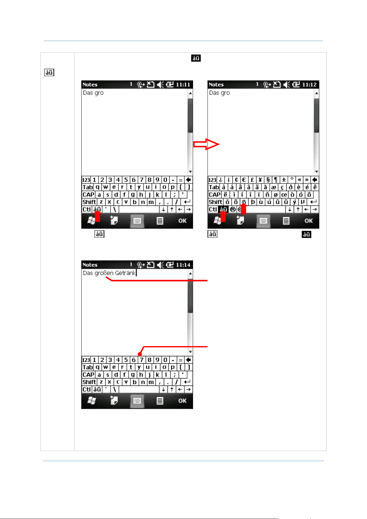
Input
modifier
Once tapped, it becomes color-inverted and presents a series of accented vowels
such as ä, æ , ë, ï, ö , ú or letter variants such as ß and ç which are needed for European
languages. It quits once a character key is tapped.
Tap key on onscreen keyboard.
key becomes color-inverted .
Then tap a character key.
After the letter variant “ß” is entered, the
onscreen keyboard restores to normal
English alphanumeric layout.
Letter variant “ß” is entered.
Once an accented vowel or
letter variant is entered, the
onscreen keyboard restores
to English keyboard.
27
Page 42

CP50 Mobile Computer Reference Manual
Diacritical letters and letter variants are presented bother lowercase and
uppercase.
Lowercase
Uppercase
OTHER KEYS
Key
Description
Tab key
Navigates among the highlight items in some applications. For text input, it
inserts Tab character, which means it moves caret to the next tab stop.
Backspace
Erases the characters to the left of caret.
Enter key
Executes a command or confirms input. When text input, it inserts a break
between paragraphs.
Navigation keys
Move caret in an input field. In certain applications, they navigate vertically or
horizontally among highlight items.
Spacebar
Inserts a blank space where caret is.
DICTIONARY
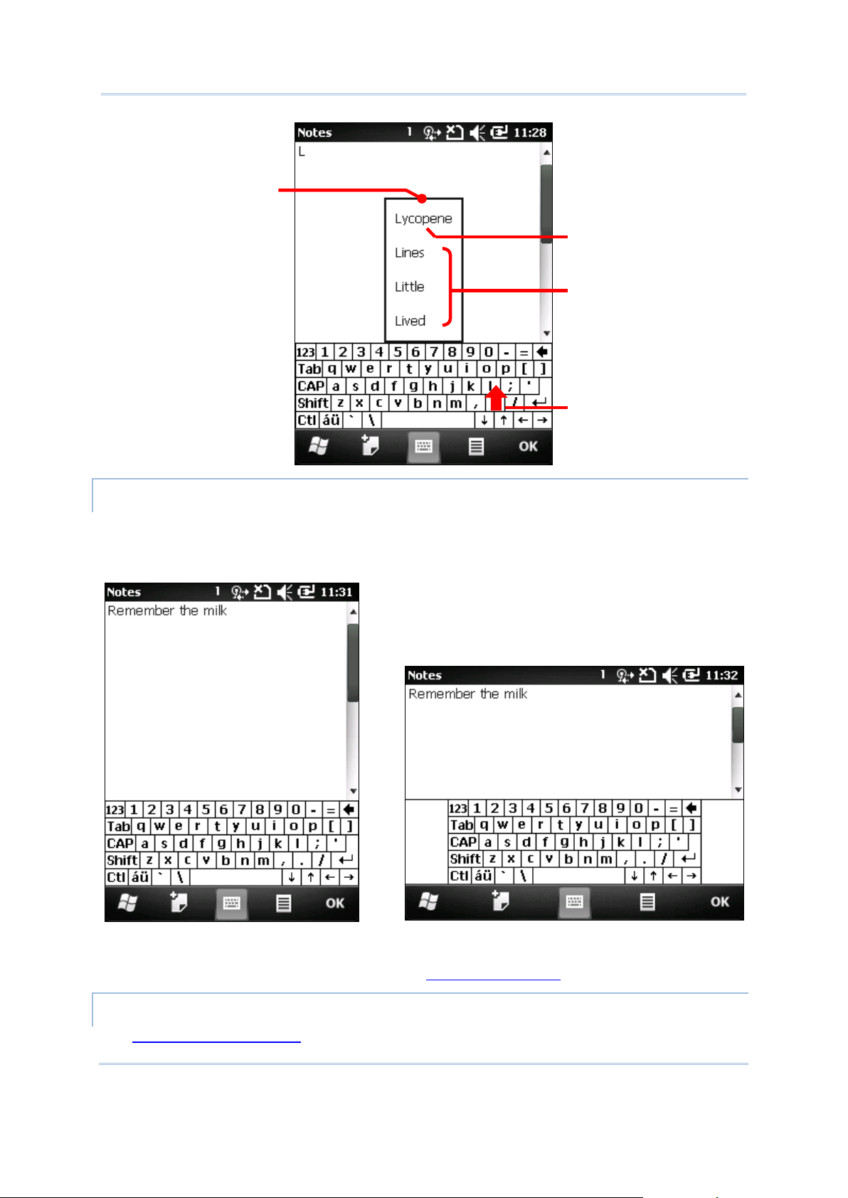
Onscreen keyboard comes with an English dictionary. When onscreen keyboard is opened,
the dictionary is enabled and lets you quick-enter the words you’re typing.
When you tap a letter key on the onscreen keyboard, a list of suggested words displays
shortly over the keyboard. Tap a suggested word from the list to enter it. When you have
entered a word that is not in the dictionary, it is added to the dictionary and becomes a
suggestible word next time.
The screenshot below shows an example when “L” is entered on onscreen keyboard:
28
Page 43
Use Mobile Computer
Upright (Portrait Mode)
Sideways (Landscape Mode)
A word previously added to
dictionary and became
suggestible
Dictionary’s inherent
suggestions
A list of suggested
words briefly display
over the keyboard
“L” is entered.
CHANGE KEYBOARD ORIENTATION
The mobile computer is built-in with a G-sensor and supports screen orientation, which is
enabled by default. So when the mobile computer turns sideways or upright, the screen
changes its orientation, and onscreen keyboard readjusts itself to the new orientation.
To disable Automatic screen rotation, see Screen Orientation.
CHANGE TEXT INPUT SIZE
See Change Input Text Size.
29
Page 44
CP50 Mobile Computer Reference Manual
HANDWRITING RECOGNITION
Onscreen text input doesn’t necessarily rely on onscreen keyboard. “Handwriting
Recognition” can also get the job done. “Handwriting Recognition” is an input method that
interprets and converts user’s handwriting received through touchscreen to text.
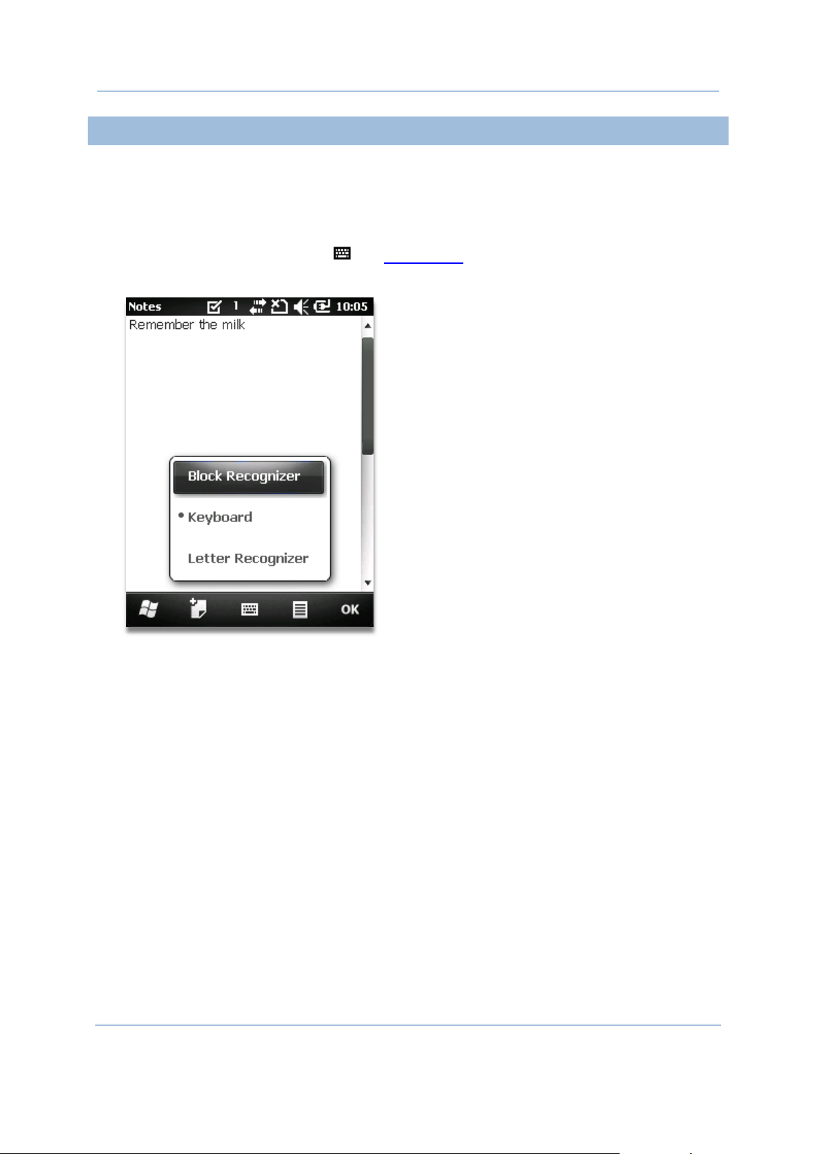
A few handwriting “input methods” are bundled with the O.S. To launch them:
1) Tap & hold the keyboard icon on Softkey bar
A context menu pops up.
2) Select between Block Recognizer and Letter Recognizer for handwriting recognition.
30
Page 45

Use Mobile Computer
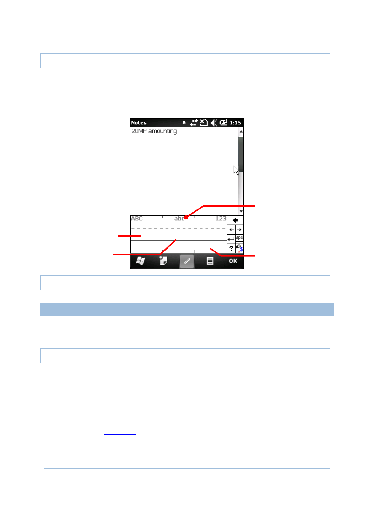
BLOCK RECOGNIZER
Block Recognizer
Draw individual letters here.
Draw individual numbers here.
Also known as “Graffiti”, a writing system used on Palm O.S.-based PDAs. It recognizes
handwriting by the particular “neography” that relies on user drawing an uppercase letter
with a single stroke. The name comes from the feature of its drawing area divided to two
blocks to admit each letters-drawing and numbers-drawing.
To enter text:
Write any letter, number, and punctuation with a single stroke. Block Recognizer then
converts it into typed text.
31
Page 46
CP50 Mobile Computer Reference Manual
LETTER RECOGNIZER
Letter Recognizer
Draw individual
uppercase letters here.
Draw individual lowercase
letters here.
Draw individual numbers here.
“Letter Recognizer” presents a writing pad divided in three areas. Each respectively detects
uppercase letters, lowercase letters, and numbers/symbols/punctuations.
To enter text:
Write individual letters, numbers, and numbers/symbols in respective area. Letter
Recognizer then converts them to typed text.
CHANGE TEXT INPUT SIZE
See Change Input Text Size..
EDIT TEXT
On the mobile computer, cut, copy, and paste text within an application or across
applications by the menu commands. Some applications don’t support editing some or all of
the text they display while others may offer their own way to edit text.
EDIT TEXT IN INPUT FIELDS
To edit text in a text input field:
1) Tap where you want to edit text.
Caret moves there and manifests itself as a vertical bar that blinks to indicate where the
typed or pasted text will be inserted.
2) Type, paste or delete text.
To paste text, see Paste Text.
32
Page 47

Use Mobile Computer
SELECT TEXT
When you see some text on a page you want to copy, select it first. Selecting texts varies
from application to application. But primarily it takes you to tap & hold somewhere on the
text to open a context menu or open the applications’ option menu which provide
commands to select a text.
To select a text:
1) Tap & hold somewhere on the text.
A context menu comes up.
2) Tap the command that makes selection.
3) Select the desired text.
It relies on defining the start and end to make selection of a text. Some applications
support tapping and dragging along the text to select it while others require you to mark
the start and end of the desired text with the onscreen facility featured by the
application.
CUT OR COPY TEXT
After a text is selected, system then presents Copy/Cut commands on “Softkey bar” or a
context menu shows up featuring Copy/Cut commands. Tap them to copy/cut the selected
text.
PASTE TEXT
Within the O.S., texts can be copied to and from between applications.
To paste a text:
1) Tap & hold the text field where you want to paste the text.
Context menu opens.
2) Tap the “Paste” command from the context menu.
The copied/cut text is pasted.
33
Page 48

CP50 Mobile Computer Reference Manual
TOUCH CONTROL
The mobile computer’s LCD is overlaid by a resistive touch panel and thus forms a resistive
touchscreen. Since a resistive touchscreen locates user’s touch by the force applied on it, it
needs your operation with a pointed object such as a pen, your fingertip (fingernail) or
stylus so it takes you the easiest minimum force to trigger actions from the touchscreen.
Touch control is one of the main ways to interact with the mobile computer. Users are able
to manipulate icons, buttons, menu commands, the onscreen keyboard, or any onscreen
items with touch control.
USE TOUCHSCREEN
The mobile computer comes with a stylus. Touch-operate the mobile computer with the
stylus or simply your fingertip. Take the gestures below to work on the touchscreen:
Tap – Touch any item on the screen such as an application icon or a setting icon to work
on them, or touch any key on the onscreen keyboard to type it.
Tap & hold – Touch an item on the screen and do not release until an action occurs.
Drag – Touch and hold an item for a moment and then, without release, move the item
onscreen until you reach the target.
Flick – Quickly move your finger or stylus across the surface of the screen. Note when
the stylus contacts the screen, do not pause so you don’t drag an item instead. Flick is
helpful, for example, for scrolling up or down a list.
Double-tap – Touch quickly twice on a webpage or other screen to zoom. For example,
double-tap a section of a webpage in a web browser to zoom that section to fit the width
of the screen. Some applications such as map-info applications support picture zooming
with double-tap.
Rotate screen – On most screens, the screen rotates as the mobile computer changes
its orientations between upright and sideways. To enable/disable automatic screen
orientation, see Screen Orientation.
SCREEN ORIENTATION
The mobile computer has a built-in G-sensor for screen orientation, which is enabled by
default. To disable it:
1) Tap Windows icon on Softkey bar or hit physical Windows key .
Start screen opens.
2) Tap Settings | System | G-sensor .
G-Sensor setting opens.
3) Deselect Automatic screen rotation.
4) Tap the “OK” command on Softkey bar to apply the change and quit setting.
ADJUST BACKLIGHT
To adjust LCD backlight
1) Tap Windows icon on Softkey bar or hit physical Windows key .
Start screen opens.
34
Page 49

Use Mobile Computer
2) Tap Settings | System | Backlight .
Backlight’s Battery Power
tabbed page
Backlight settings open.
3) Select between Battery Power and External Power tabbed pages.
4) Select Manual brightness control and manually adjust the brightness level, or
deselect Manual brightness control and leave the brightness on automatic.
CALIBRATION
A resistive touchscreen needs calibration to work accurately after serving for a period of
time. Calibration aligns the coordinates of touch panel and the LCD underneath to improve
touch accuracy.
To calibrate touchscreen:
1) Tap Windows icon on Softkey bar or hit physical Windows key .
Start screen opens.
2) Tap Settings | System | Screen .
Screen settings open showing Alignment tabbed page.
35
Page 50

CP50 Mobile Computer Reference Manual
3) Tap Align Screen button.
Screen alignment application opens.
4) Accurately tap on the centers of each cross mark to show consecutively onscreen, 5 in
total.
5) Follow through the calibration.
36
Page 51

Use Mobile Computer
MEMORY
Device Information
The mobile computer packs the following memory units to retain data and instructions from
users:
Random-access Memory (RAM)
256 MB SDRAM for temporary storage and fast access of active applications. SDRAM is
fed by backup battery to hold data.
Internal Storage
2GB flash memory to store O.S. (Windows Embedded Handheld 6.5), application files,
settings, and other data used by applications.
External Storage
Insert a storage card to increase the mobile computer’s storage capacity. Supported are
MicroSD cards from 256MB to 4GB and MicroSDHC cards from 4GB to 32GB.
DATA LOSS CAUTION
When main battery is absent or used up, backup battery on the main board takes over to
supply power to the mobile computer. A fully charged backup battery retains SDRAM data
and suspends the mobile computer for 30 minutes.
Note if you are leaving the mobile computer to sit for a couple of days, data loss is to occur
when both main and backup batteries drain out. Consider backing up data before putting
away the mobile computer.
CHECK STORAGE
RAM SIZE
To check RAM size:
From Start screen, tap Settings | System | Device
Information to open Device Information. It
opens retrieving the information about the mobile
computer, including device manufacturer, device ID,
memory size, and firmware/software version. Find
RAM size among the listed.
37
Page 52

CP50 Mobile Computer Reference Manual
INTERNAL STORAGE
Memory
Internal storage
Main tabbed page
Memory’s Storage
Card tabbed page
External storage usage
RAM usage for running applications
On Start screen, tap Settings | System | Memory . Memory screen opens showing
Main tabbed page. This page gives the information about the mobile computer’s use of RAM
and internal storage.
Main tabbed page delivers two labels – Storage and Program:
Storage - Internal memory for files storage, such as O.S., applications and the files
needed for applications.
Program - RAM usage for running applications.
EXTERNAL STORAGE
When Memory screen opens, tap Storage Card tab.
Storage Card tabbed page then opens and shows
the info about external storage (when a storage card
is inserted).
38
Page 53

Use Mobile Computer
INSERT SD CARD
5) Push the hinged cover to the open
position.
6) The hinged cover unlocks.
7) Swivel up the cover.
8) Have the SD card. Position it with the
metal contacts face-down as the
signage besides the socket
illustrates. Fit the SD card into the
socket.
9) Put down the hinged cover. Push-lock
the cover.
10) Restore main battery pack and the
battery door.
By your day-to-day use of the mobile computer, available internal storage may run short.
Invest the mobile computer with an external memory unit to expand storage capacity.
Follow through the steps below to install a SD card:
1) Power off the mobile computer.
2) Place the mobile computer face-down on a flat and soft surface.
3) Remove the battery door and main battery pack as described in Main Battery Setup.
Battery chamber is opened.
4) Find SD card socket inside battery chamber. (See Inside Battery Chamber.) The SD card
socket is equipped with a hinged cover.
Figure 10: Inserting SD Card
39
Page 54

CP50 Mobile Computer Reference Manual
DIRECT DATA CONNECTION
“Direct” data connection means “hardwired” data connection between the mobile computer
and a Windows-based PC as opposed to wireless connection. Direct data connection relies
on a serial cable or a USB cable (sometimes plus an auxiliary cradle) between two devices.
Once two devices are “directly” connected with each other by a serial- or USB-cable, they
can sync data with each other, and the mobile computer, more precisely the SD card in it,
can mount the PC as mass storage.
USE CABLE
Direct data connection using a cable:
1) Connect the mobile computer to your PC with a USB- or serial-cable. Fix the cable to
both sides.
2) Power on the mobile computer if you haven’t.
3) On the mobile computer, open Start screen, tap Settings | Connections | USB
Connection .
USB Connection opens.
4) Select ActiveSync or Mass Storage.
Note: (1) RS232 serial cable doesn’t support ActiveSync.
(2) Mass Storage only mounts the external SD card.
5) Tap the “OK” command on Softkey bar to apply the change and quit setting.
See Syncing Tools and subsequent sections to know how to use ActiveSync.
Figure 11: Direct Data Connection Using Cable
USE CRADLE
Direct data connection using a cradle:
1) Seat the mobile computer in a Charging and Communication Cradle (hereinafter
“cradle”).
40
Page 55
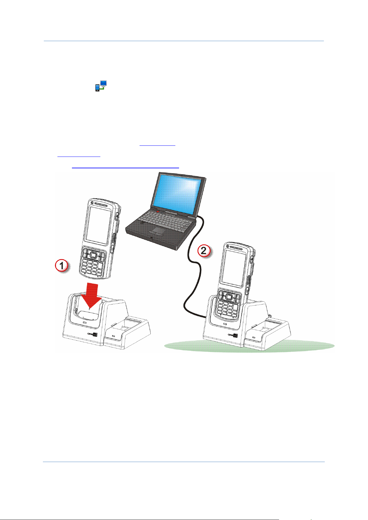
Use Mobile Computer
2) Connect the cradle to your PC with a serial- or USB cable. Fix the cable to both sides.
3) Power on the mobile computer if you haven’t.
4) On the mobile computer, open Start screen, tap Settings | Connections | USB
Connection .
USB Connection opens.
5) Select ActiveSync or Mass Storage.
Note: (1) RS232 serial cable doesn’t support ActiveSync.
(2) Mass Storage only mounts the external SD card.
6) Tap the “OK” command on Softkey bar to apply the change and quit setting.
See Syncing Tools and subsequent sections to know how to use ActiveSync.
See also Charging & Communication Cradle.
Figure 12: Direct Data Connection Using Cradle
41
Page 56

CP50 Mobile Computer Reference Manual
SYNCING TOOLS
O.S.
Syncing Program
Windows Vista or Windows 7
WMDC
Windows XP SP3 and earlier
ActiveSync
Sync Partnership
Services
Synchronization Relationship
Two computers to sync Microsoft Office Outlook data with each
other.
PC to add and remove programs to/from the mobile computer.
PC to browse files on the mobile computer.
PC to copy files to/from the mobile computer.
PC to back up the files on the mobile computer.
Temporary Relationship
(Mobile computer works as a
“guest” for PC.)
PC to add and remove programs to/from the mobile computer.
PC to browse files on the mobile computer.
PC to copy files to/from the mobile computer.
PC to back up the files on the mobile computer.
Microsoft’s syncing tools enables users to update or back up the data on their handheld
computers to desktop computers.
Two syncing tools are featured by Microsoft - ActiveSync and Windows Mobile Device Center
(hereinafter “WMDC”). Which tool to use depends on which OS is running on your PC. See
the rule below:
ActiveSync and WMDC are downloadable from Microsoft’s website. Download and install the
right one on your PC.
Hereafter in this manual, we will focus on ActiveSync only. For WMDC usage, see its
documentation or help file.
SYNC PARTNERSHIP
Once a USB direct connection is established between the mobile computer and your PC as
described in Use Cable or Use Cradle, they are able to form the following ties:
Note ActiveSync isn’t available with serial cable but USB cable only, and data stored on
external storage (the SD card) cannot be synchronized.
See ActiveSync Actions to Take that details each aforesaid service.
42
Page 57

Use Mobile Computer
1ST USB SYNC
ActiveSync Sync
Setup Wizard
opens.
Press Cancel to create
“Temporary Relationship” by
which the mobile computer
works as a “guest” to the PC.
Press Next to set up
“Synchronization
Relationship”.
This section will guide you to USB syncing. For Bluetooth syncing, see Bluetooth ActiveSync.
To connect ActiveSync using USB:
1) Download the right syncing tool as described in Syncing Tools and install it on your PC.
2) Connect the mobile computer and your PC as described in Use Cable or Use Cradle.
3) On the mobile computer, make sure ActiveSync is enabled. Check by Start screen |
Settings | Connections | USB connections .
4) On your PC, run the syncing program.
ActiveSync should detect the mobile computer. Sync Setup Wizard launches and
prompts to set up “Sync Partnership” between two computers
43
Page 58

CP50 Mobile Computer Reference Manual
5) Press Next button for “Synchronization Relationship”, or press Cancel button for
The mobile computer
connected as a “guest” to the
PC.
Two computer are
“Temporary Relationship” if you don't plan to connect to the PC on a regular basis.
If you have pressed Next, follow the onscreen instructions to go through the setup of
“Synchronization Relationship”. Once setup finishes, ActiveSync opens showing
“Synchronizing”. Two computers are synchronized.
OR
If you have pressed Cancel, Microsoft ActiveSync opens showing “Guest” and
“Connected”. Two computers are connected.
44
Page 59

Use Mobile Computer
DISCONNECT USB ACTIVESYNC
To disconnect USB ActiveSync:
1) On your PC, open ActiveSync by double-clicking its icon in the notification area.
ActiveSync opens.
2) From the menu bar, click File | Connection Settings.
[Connection Settings] window opens.
3) Deselect Allow USB connections.
4) Press the OK button to apply the change and quit setting.
So when you plug your mobile computer the next time, it still gets charged but
ActiveSync won’t attempt to synchronize with it.
To disconnect Bluetooth syncing, see Disconnect Bluetooth ActiveSync.
45
Page 60

CP50 Mobile Computer Reference Manual
ACTIVESYNC ACTIONS TO TAKE
Once “Synchronization Relationship” or “Temporary Relationship” is up between two
computers, a variety of actions can be taken to enhance the resources sharing between
them as previously mentioned in Sync Partnership.
In summary, “Synchronization Relationship” outshines “Temporary Relationship” by being
capable of syncing Microsoft Office Outlook data. However “Temporary Relationship”
provides satisfactory file sharing if you don’t want to synchronize information.
See the following to know what actions to take with ActiveSync:
CHANGE MICROSOFT OFFICE OUTLOOK DATA TO SYNCHRONIZE
Note this is for “Synchronization Relationship” only.
In default state, “Synchronization Relationship” doesn’t synchronize all Microsoft Office
Outlook data but only a limited amount between two computers in order to save storage on
the mobile computer. You can change the amount of information to synchronize:
1) On your PC, from the menu bar of ActiveSync, select Tool | Options.
ActiveSync’s [Settings] window opens showing Options tabbed page.
2) Select an information type to synchronize, and deselect an information type to stop
synchronizing.
3) Press OK button to save the change and quit setting.
Note you can also change the information to synchronize on the mobile computer in that
you have to disconnect ActiveSync first as mentioned in Disconnect USB ActiveSync or
Disconnect Bluetooth ActiveSync and then tap ActiveSync’s “Menu” command on
Softkey bar and tap Options.
46
Page 61
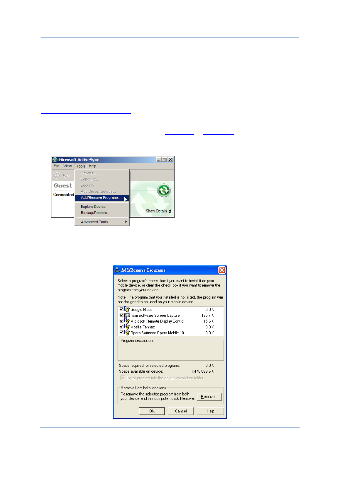
Use Mobile Computer
ADD/REMOVE PROGRAMS
Note basically the applications to be installed to the mobile computer need to be installed on
your PC first. So download the application programs to your PC first and install them on your
PC so they can be installed onto the mobile computer later.
Many application programs are installed in different ways. Read their installation guides or
documentation to know how they are installed. If you are installing an application that
cannot be installed on your PC first, try to install it right from the mobile computer, see
Download & Install Applications for more details.
To install an application on the mobile computer:
1) Connect two computers as described in Use Cable or Use Cradle.
2) Sync two computers as described in 1st USB Sync.
3) On the PC, from the menu bar of ActiveSync, select Tools | Add/Remove Programs.
ActiveSync starts to search for the application programs installed on your PC and opens
its [Add/Remove Programs] dialog which lists those found. Each entry comes with a
check box on the left. An unchecked box means the program is yet to install to the
mobile computer while a checked one means an installed program.
47
Page 62

CP50 Mobile Computer Reference Manual
4) Select the application program(s) to install to the mobile computer, and deselect the
application program(s) to uninstall from the mobile computer.
5) Hit the OK button.
ActiveSync proceeds to install programs and/or remove programs to/from the mobile
computer.
6) Follow the onscreen instructions on both your PC and the mobile computer to proceed.
Noteworthy facts:
Normally the application program(s) downloaded from external resources are installed
to the mobile computer’s directory at Mobile Device\Program Files. However
sometimes there are exceptions and it depends on the application.
You can uninstall application(s) right by the mobile computer rather than by the PC. See
Uninstall Applications for more details.
If an installed application program isn’t listed among the installed ones, browse for it
using File Explorer . Tap & hold it, and select Delete from the context menu that
pops up.
ADD APPLICATION SHORTCUTS TO START SCREEN
ActiveSync features “Explore” to add an application shortcut to Start screen where it is
easier to launch the application.
To add an application shortcut to Start screen:
1) Connect two computers as described in Use Cable or Use Cradle.
2) Sync two computers as described in 1st USB Sync.
3) On the PC, from ActiveSync’s menu bar, select Tools | Explore Pocket PC, or from its
toolbar, press Explore button.
The mobile computer’s internal storage’s root directory “Mobile Device” opens
presenting a few folders (and files).
48
Page 63

Use Mobile Computer
4) Double-click My Windows Mobile-Based Device .
My Windows Mobile-Based Device opens.
5) Double-click Program Files.
Program Files folder opens. This is where the downloaded applications are normally
installed on the mobile computer’s local storage.
In the folder, each sub-folder stores an application.
6) Open the folder of the application to create shortcut for.
7) Find the executable file of that application. Right-click on it and select Copy from the
context menu that comes up.
The executable file is copied.
8) Browse for My Windows Mobile-Based Device\Windows\Start Menu\Programs.
Programs folder opens.
9) Right-click any vacancy in the folder and select Paste shortcut from the context menu
that comes up.
A shortcut to the application is added to Start screen.
Note: You can also copy & paste by the sequence Create Shortcut -> Cut -> Paste.
You can also add an application shortcut to Start screen right by the mobile computer. See
Add Items to Start Screen for more details.
ADD FILE SHORTCUTS TO START SCREEN
ActiveSync features “Explore” to add to Start screen a shortcut to some local file so it is
accessible more easily.
To add a file shortcut to Start screen:
1) Connect two computers as described in Use Cable or Use Cradle.
2) Sync two computers as described in 1st USB Sync.
3) On the PC, from ActiveSync menu bar, select Tools | Explore Pocket PC, or from its
toolbar, press Explore button.
The mobile computer’s internal storage root directory “Mobile Device” opens
presenting a few folders.
4) Browser for the file to create shortcut for.
5) Right-click on the file and select Copy from the context menu that comes up.
6) Browse for My Windows Mobile-Based Device\Windows\Start Menu\Programs.
Programs folder opens.
7) Right-click any vacancy in the folder and select Paste shortcut from the context menu
that comes up.
A shortcut to the file is added to Start screen.
Note: You can also copy & paste by the sequence Create Shortcut -> Cut -> Paste.
49
Page 64

CP50 Mobile Computer Reference Manual
You can also add a file shortcut to Start screen right by the mobile computer. See Add Items
to Start Screen for more details.
REMOVE SHORTCUTS FROM START SCREEN
Note the inherent shortcuts aren’t removable. Only the added shortcuts are removable.
To remove an added shortcut from Start screen, simply use ActiveSync’s Explore to
delete the shortcut from My Windows Mobile-Based Device\Windows\Start
Menu\Programs folder.
You can also remove an added shortcut from Start screen right by the mobile computer. See
Remove Items from Start Screen for more details.
CREATE NEW FOLDERS
To create a new folder on the mobile computer:
1) Connect two computers as described in Use Cable or Use Cradle.
2) Sync two computers as described in 1st USB Sync.
On the PC, from ActiveSync menu bar, select Tools | Explore Pocket PC, or from its
toolbar, press Explore button.
The mobile computer’s internal storage root directory “Mobile Device” opens
presenting a few folders (and some files).
3) Browse where you want to create a folder.
4) Right-click any vacancy there.
Context menu opens
5) Select New Folder.
A new folder is created.
BACKUP DATA
To best protect your work, back up regularly the data on your mobile computer. Manually
back up using ActiveSync by either “Synchronization Relationship” or “Temporary
Relationship” with simple copy & paste to back up files to your PC.
USB PASS-THROUGH NETWORKING
ActiveSync supports “Pass-Through Networking” whereby the mobile computer networks
using your PC’s data connection.
For security, disable the network bridging on the PC, especially the bridging to a Remote
NDIS adapter. For more information on network bridging, see Windows Help on the PC.
After sync partnership is up between the mobile computer and your PC:
1) On your PC, from the menu bar of ActiveSync, select File | Connection Settings.
[Connection Settings] window opens.
2) For This computer is connected to, select a network which your PC should connect to
when passing through ActiveSync. Options are:
50
Page 65

Use Mobile Computer
Option
Description
Automatic
Auto-detects proxy
This option detects if a proxy should be used when passing connections
through the PC. If yes, configure the proxy on the mobile computer.
This option best suits connecting to a PC (laptop) that may be used at
home (with no proxy), as well as to a corporate network (with proxy).
Work Network
Always uses proxy
This option assumes a proxy should be used when passing connections
through the PC, and uses whatever proxy is already configured on the
mobile computer.
This option best suits connecting to a PC that is always on corporate
network.
The Internet
Never uses proxy
This option assumes no proxy is necessary when passing connections
through the PC.
This option best suits connecting to a PC connected directly to the
Internet through ISP (at home)
3) Select Open ActiveSync when my device connects.
4) Hit OK button to apply the change and quit setting.
To pass-through network using Bluetooth, see Bluetooth Pass-through Networking.
Compare USB Internet Sharing.
51
Page 66

CP50 Mobile Computer Reference Manual
CHARGING & COMMUNICATION CRADLE
Press bolt to
release
converter
The direct Charging & Communication Cradle is developed for what its name announces. It
isn’t provided bundled but an accessory to opt for. This cradle saves you from the trouble of
perpetual plugging and unplugging USB/serial cable.
This cradle comes with an additional station for charging a spare battery. It also features
an USB host connector to expand the connectivity to hardware peripherals.
USE CONVERTER
The cradle features a converter to dock the mobile computer whether gripped or ungripped.
Installed with converter, the cradle seats a ungripped mobile computer.
To use converter:
1) Place converter onto cradle.
2) Click the converter carefully in place.
3) Check the rear of cradle. Make sure converter is bolt-locked.
Figure 13: Use Cradle Converter
52
Page 67

Use Mobile Computer
OVERVIEW
Number
Description
1
Main charging station
2
Spare battery charging station
3
Main charging station status LED.
This status LED lights on green when external power is connected.
4
Spare battery charging station status LED.
This status LED delivers the following conditions:
Status
Description
Green on
Spare battery fully charged.
Red slow blinking
Spare battery being charged.
Red fast blinking
Charging error. Spare battery is defective or out of charging
temperature range, or spare battery’s contact with charging
station is imperfect.
5
USB Host connector (Standard A Host)
6
USB Client connector (Micro-B)
7
Power jack
8
Converter lock bolt.
To release converter, press this bolt.
9
Converter (for ungripped mobile computer)
Figure 14: Cradle Overview
Note: For the mobile computer’s charging status, check the status LED on the mobile
computer.
53
Page 68

CP50 Mobile Computer Reference Manual
PISTOL GRIP
As an accessory to opt for, the Pistol Grip is a snap-on handle that gives the mobile
computer not only gun form factor but also trigger capability for intensive scanning.
INSTALL PISTOL GRIP
Slide the terminal into pistol grip until it clips in place.
SCAN
To scan using Pistol Grip:
1) Launch scan engine(s) by running one of the reader utilities on the mobile computer.
2) Aim the mobile computer’s scan window at the barcode to read.
OR
Tap (slightly contact) the mobile computer’s scan window with the RFID tag to read.
3) Pull the trigger on Pistol Grip.
UNINSTALL PISTOL GRIP
Pull back the clip while at the same time withdraw Pistol Grip.
54
Page 69

Use Mobile Computer
AUDIO PLAYBACK
Volume Control
System volume
Ringer volume
In-call volume
Physical Volume Rocker
Yes
No
Yes
Onscreen Volume Gauge
Yes
Yes
Yes
Title bar Volume Icons
Yes
Yes
No
Headset jack is
sealed with a hinged
rubber.
Use a headset for audio playback and hands-free telephone communication.
The headset jack (3.5 mm DIA) is built up on one side of the mobile computer and sealed
with a hinged rubber. Open the rubber to reveal the headset jack. Plug the connector of
your headset to the jack.
Bluetooth headsets are supported to deliver better mobility. See Use Bluetooth.
Figure 15: Audio Playback
VOLUME CONTROL
The mobile computer has two volume control facilities – the physical volume rocker
perching on the waist of the mobile computer and the onscreen volume gauges featured by
the O.S.
The physical rocker controls the system volume (media playback and event/notification
sounds) and in-call volume. The onscreen gauge bests the physical rocker by adjusting
phone ringer volume additionally.
When either the system volume or phone ringer volume is enabled, the O.S. shows an
icon on Title Bar; otherwise it shows an . See the table after the break for a summary.
PHYSICAL VOLUME ROCKER
Use physical volume rocker to turn up and down system volume and in-call volume. Note
this volume rocker doesn’t adjust phone ringer volume, which is only controllable by an
onscreen volume gauge. And in-call volume is only adjustable when a call is ongoing. See
also Options during A Call.
55
Page 70
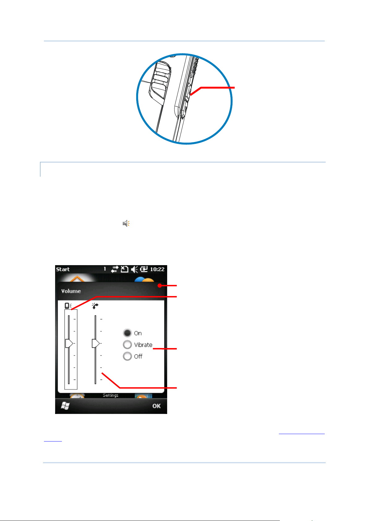
CP50 Mobile Computer Reference Manual
Turns up and down
system and in-call
volumes.
Adjusts system volume
Adjusts phone ringer volume
[Off] mutes both system and
phone ringer volumes while
[Vibrate] mutes the phone
ringer and enables phone
Onscreen volume facility
Figure 16: Physical Volume Rocker
ONSCREEN VOLUME GAUGES
The onscreen volume gauges adjust all three of system, phone ringer and in-call volumes.
To adjust any of them:
1) Tap Title bar at the top of the screen.
A horizontal drop-down bar opens.
2) Tap the volume icon .
[Volume] dialog opens presenting the gauges for system volume and phone ringer
volume. Three radio buttons [On], [Off] and [Vibrate] are featured on the right. Select
[On] or [Off] to enable or mute both volumes while selecting [Vibrate] mutes the phone
ringer and enables phone vibrate.
3) Make the setting that meets your needs.
Note the in-call volume gauge is only available when a call is ongoing. See Options during
A Call for more details.
56
Page 71

IN THIS CHAPTER
Launch Reader Module(s) .................................................. 58
Read Printed Barcodes & RFID Tags .................................... 59
Configure Reader(s) .......................................................... 60
DATA CAPTURE
Although highly converged, the mobile comptuer is a dedicated barcode/RFID reader. The
mobile computer ships with either a (laser) 1D reader or 2D imager and sometimes plus an
RFID reader. A number of symbologies and RFID tags are supported and data about them
can be decoded and collected.
A high-specced 5.0 mega-pixel camera is also recessed on the rear of the mobile computer
to capture images to better meet your field applications.
Done with the data collection, the mobile computer outputs the collected data to the host
computer so data storage, advanced data analysis and more special services can be
performed.
You will learn how to collect data with reader modules in this chapter while collecting images
with camera is detailed in the following chapter Camera.
57
Page 72

CP50 Mobile Computer Reference Manual
LAUNCH READER MODULE(S)
ReaderConfigMobile.exe opens.
The mobile computer reads printed barcodes and RFID tags. The reader modules can be a
(laser) 1D reader or a 2D imager plus an RFID reader, and never be a (laser) 1D reader plus
a 2D imager. The two don’t coexist on the mobile computer. They rule out each other since
they both read barcodes.
It relies on CipherLab’s ReaderConfigMobile.exe to launch the reader module(s).
ReaderConfigMobile.exe is provided bundled with the mobile computer. Run it to launch
reader module(s).
To launch reader module(s):
1) Open Start screen, tap CipherLabUtilities .
CipherLabUtilities opens.
2) Tap Reader Configuration .
ReaderConfigMobile.exe opens in context with the available reader module(s) on board
the mobile computer.
The mobile computer readies to read printed barcodes (and RFID tags).
3) Proceed to collect data as described in Read Printed Barcodes & RFID Tags.
OR
If you want to, configure the reader module(s) first as described in Configure Reader(s)
before starting collecting data.
58
Page 73

Data Capture
READ PRINTED BARCODES & RFID TAGS
Before you start out collecting data, configure the reader module(s) using
ReaderConfigMobile.exe as described in Configure Reader(s), or skip the configuration and
go straight to collect data.
To collect data:
1) Launch the reader module(s) as described in Launch Reader Module(s).
2) Configure the reader module(s) if you want to.
3) Run a text editor on the mobile computer or connect the mobile computer to a remote
computer so there is somewhere to admit the decoded data.
4) Find the scanning window on the top of the mobile computer. Point it at the printed
barcode to read while holding the mobile computer steady a few inches from the
barcode.
OR
Find the scanning window on the top of the mobile computer. Tap (slightly contact) the
scanning window with the RFID tag.
5) Press the physical SCAN key (or either side trigger) on the mobile computer.
The scanning light beams to read the printed barcodes, or RFID tags are read.
The scanning light goes off upon data decoding or decoding timeout.
Figure 17: Reading Printed Barcodes
59
Page 74

CP50 Mobile Computer Reference Manual
CONFIGURE READER(S)
ReaderConfigMobile.exe opens
General tabbed page
displays by default.
Symbologies and About
tabbed pages are hidden.
ReaderConfigMobile.exe is meant to launch and configure reader modules. Use it to create
the application that best suits your needs.
To open ReaderConfigMobile.exe:
1) On Start screen, tap CipherLabUtilities .
CipherLabUtilities opens.
2) Tap Reader Configuration .
ReaderConfigMobile.exe launches in context with the reader module(s) on board the
mobile computer. The software opens showing General tabbed page while hiding
Symbologies and About tabbed pages.
The following will guide to all aforesaid tabbed pages.
GENERAL TABBED PAGE
General tabbed page is where all reader settings are accessed from except for symbologies
settings. General tabbed page presents settings by rectangle GUI buttons and check boxes.
Each GUI buttons can be tapped to open a setting page. General tabbed page also features
a field to deliver the result of test-scan.
To open General tabbed page:
1) Launch ReaderConfigMobile.exe as described in Configure Reader(s).
The software launches showing General tabbed page.
60
Page 75
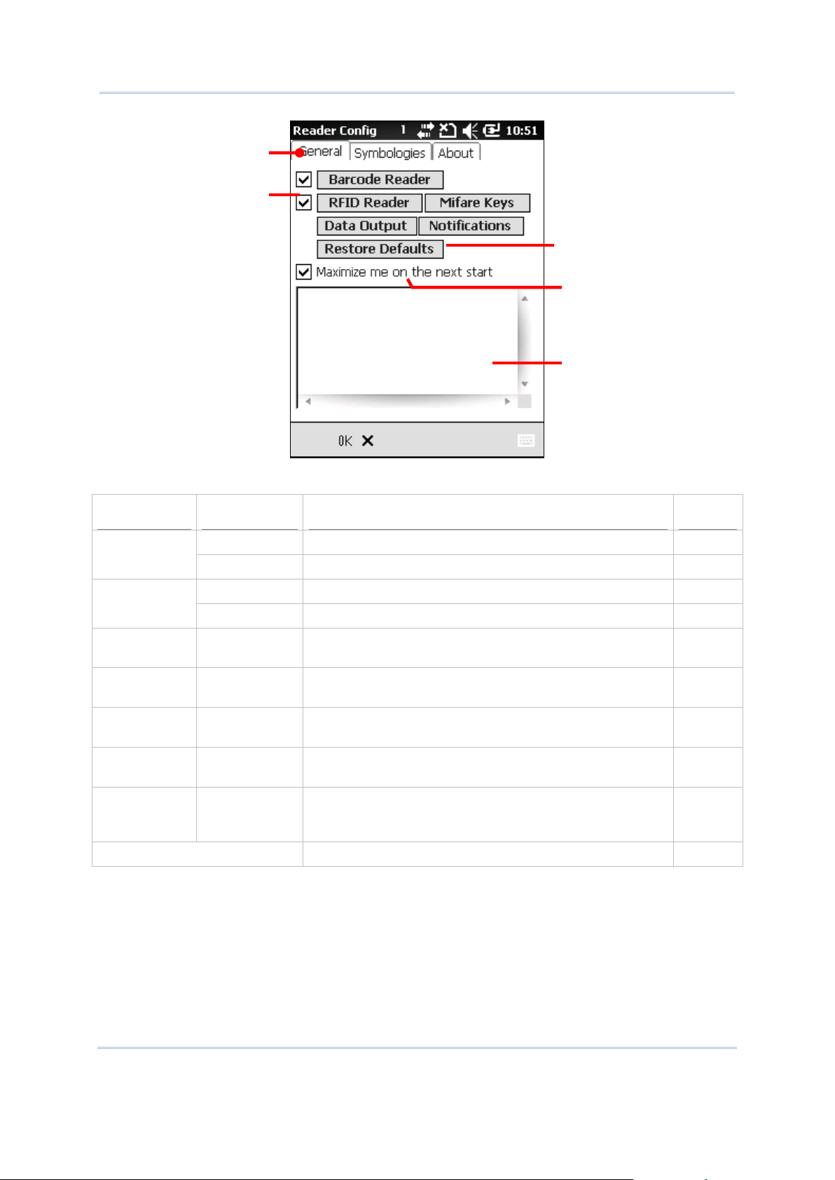
Data Capture
The facilities on General tabbed page are tabulated as follows:
Setting
Facility
Description
Default
Barcode
Reader
Check box
Enables/disables 1D (laser) reader or 2D imager
Selected
GUI button
Opens barcode reader setting page
--
RFID Reader
Check box
Enables/disables RFID scan engine
Selected
GUI button
Opens a page that sets RFID reading.
--
Mifare Keys
GUI button
Opens a page that changes key A and B to read/write
RFID-tags.
--
Data Output
GUI button
Opens a page that sets where and how to output
decoded data.
--
Notifications
GUI button
Opens a page that sets how to notices users of good
read.
--
Restore
Defaults
GUI button
Recovers default settings.
--
Maximize me
on the next
start
Check box
Enlarges the window to full-screen size when the
software relaunches.
Selected
Input Field
Delivers user’s test-scanned data.
--
General tabbed page
Delivers test-scan result
[RFID Reader] & [Mifare
Keys] are only available
when the mobile computer
includes an RFID reader
Recovers default settings.
Maximizes the utility’s
window when relaunch
61
Page 76

CP50 Mobile Computer Reference Manual
BARCODE READER
Setting
Description
Default
Decode Session Timeout
Defines the maximum time for a decoding act. 1 through 9
sec configurable.
3 sec
Redundancy level
Sets how many successful readings should be done before
a barcode can be decoded.
1
Scan angle
Sets the scan angle for laser scan engine.
Wide
Scan mode
Sets the reader’s scanning behaviour. Options available
are Continuous and Laser modes.
Laser
Barcode Reader features a check box and a GUI button on General tabbed page. The
check box is selected by default. Deselect it to disable the 1D (laser) reader or 2D imager,
which is occasionally needed when an RFID reader coexists on the mobile computer and you
only want the RFID tags to be read, lest printed barcodes should be read and decoded.
The Barcode Reader GUI button can be tapped to open a setting page that configures your
barcode reading.
To open Barcode Reader setting page:
1) Open General tabbed page as described in General tabbed page.
General tabbed page opens.
2) Tap Barcode Reader button.
Barcode Reader setting page opens.
Featured settings are different for 1D (laser) reader and 2D imager:
1D (laser) reader settings 2D imager settings
1D (LASER) READER SETTING
62
Page 77

Data Capture
Timeout between
symbologies
Sets the time for the barcode reader to resurrect its ability
to once more decode a barcode it just decoded.
Only available for Continuous mode.
1 sec
Caps Lock
Capitalizes the literal-characters among decoded data.
None
Inter Character Delay
Sets the delay time between each output character (by
millisecond).
0
2D IMAGER SETTING
Setting
Description
Default
Decode Session Time-out
Defines the maximum time for a decoding act. 1 through 9
sec are configurable.
3 sec.
Enable decoding
Illumination
Enables beaming a flash of light (internal LED) to aid
reading a printed barcode.
Selected
(Enabled)
Enable decoding aiming
pattern
Enables projecting a crosshair to aim at the printed
barcode to read.
Selected
(Enabled)
Redundancy level
Sets how many successful readings should be done before
a barcode can be decoded.
Level 1
Security Level
Sets the security level to ensure decoding accuracy
considering the printed quality of the barcodes such as
Code 128, Code 93, and UPC/EAN. The higher the level is,
the more security is ensured. Options are:
Level
Description
0
With this default, the scan engine is aggressive
enough to decode most “in-spec” barcodes.
1
Select this level if misdecodes have occurred.
It fixes most misdecodes.
2
Select this level if Level 1 should fail to
eliminate misdecodes.
3
Select this level if Security Level 2 should fail
to prevent misdecodes. However, as this level
actually impairs the decoding ability of scan
engine, it’d be better to improve barcode’s
print quality if this level should be needed.
Level 0
Caps Lock
Capitalizes the literal-character among the decoded data.
None
Inter Character Delay
Sets the delay time between each output character (by
millisecond).
0
63
Page 78

CP50 Mobile Computer Reference Manual
RFID READER
1)
Open General tabbed page as
described in General tabbed page.
General tabbed page opens.
2)
Tap RFID Reader button.
RFID Reader setting page opens. It
features two check boxes - Read
blocks and Write blocks atop other
settings.
3)
Select Read blocks to read data
from an RFID tag; or select Write
blocks to write data to an RFID tag.
Selecting Read blocks or Write
blocks renders different settings:
RFID Reader
settings page
(for read
operation)
Read block setting Write block setting
When an RFID reader is detected, RFID Reader becomes available on General tabbed
page.
RFID Reader comes with a check box selected by default. Deselect it to disable the RFID
reader on the mobile computer. This is occasionally needed when you only want to read
printed barcodes, lest RFID tags should be read and decoded.
The RFID Reader GUI button can be tapped to open a setting page that tunes your RFID
reading.
To open RFID Reader setting page:
64
Page 79

Data Capture
Featured settings are enumerated as follows:
Setting
Descriptions
Default
Read blocks
Reads data from an RFID tag
Selected
Login Key
Shows what key A and key B currently is.
Keys A and B are what the RFID reader module
relies on to access (read or write) an RFID tag. In
default state, both keys are a sequence of twelve
“F” characters because they are Mifare tag’s
factory default.
If necessary, modify these default keys by Mifare
Keys setting. (See
Mifare Keys.)
Key A &
FFFFFFFFFFFF
Start Position
Defines where to start reading data from.
-1 (default block,
byte 0)
See Appendix
IV: RFID Tag
Default Block.
Reading length
(byte)
Defines how many bytes of data to read.
10
Display hex value
Displays decoded data in hex values.
Generally the readable RFID data lies in user
block. If the data to collect confides in a non-user
block such as the lock block, select Display hex
values lest the data to collect involves any
invisible character.
Deselected
Setting
Descriptions
Default
Write blocks
Writes data to an RFID tag
Deselected
Login Key
Shows what key A and key B currently is.
Keys A and B are what the RFID reader module
relies on to access (read or write) an RFID tag. In
default state, both keys are a sequence of twelve
“F” characters because they are Mifare tag’s
factory default.
If necessary, modify these default keys by Mifare
Keys setting. (See
Mifare Keys.)
Key A &
FFFFFFFFFFFF
Start byte to write
Defines where to start writing data to.
-1 (default block,
byte 0)
See Appendix
IV: RFID Tag
Default Block.
Use hex values
Writes data in hex values.
Generally a RFID tag’s writeable block is the user
block. However, if the block to write is a non-user
block such as the lock block, select Use hex
Deselected
READ BLOCKS SETTINGS
WRITE BLOCKS SETTINGS
65
Page 80

CP50 Mobile Computer Reference Manual
values to write data in hex values lest the block to
write involves any invisible character.
Input string to
write
Defines what to write.
Note as different RFID tags may have different
default blocks (also “pages”), and different
amount of bytes and number of blocks. The data
written is truncated to fit the blocks of the targeted
RFID tag. Therefore part of the data may be
discarded when it comes to the end of a block end.
See Appendix IV: HF RFID Reader to know RFID
Tag Default Block.
--
Note: Refer to the specifications of the RFID tag to read for its memory organization.
66
Page 81

Data Capture
MIFARE KEYS
Settings
Descriptions
Default
Key A
Assigns new key A, which must be a hex string of 12
bytes.
If it is the other key (key B) that you want to
change, you still need to assign the current key A
here to be able to enact the change.
--
Key B
Assigns new key B, which must be a hex string of 12
bytes.
If it is the other key (key A) that you want to
change, you still need to assign the current key B
here to be able to enact the change.
--
Sector
Sets the blocks to apply the change.
1
(blocks 4, 5,
& 6)
[Mifare Keys] setting
Shows what each key A
and B currently is.
Assigns the blocks
to apply change
Tap this button to enact the
change.
Mifare Keys setting changes the security keys A and/or B for a Mifare tag’s data block.
Keys A and B are two keys that enable the RFID reader to access (read or write) a Mifare
tag’s data block.
To open Mifare Keys setting page:
1) Open General tabbed page as described in General tabbed page.
General tabbed page opens.
2) Tap Mifare Keys button.
Mifare Keys setting page opens.
To perform change to key A and/or B:
1) Launch RFID reader as described in Launch Reader Module(s).
67
Page 82

CP50 Mobile Computer Reference Manual
2) Open Mifare Keys setting page as mentioned in Mifare Keys.
3) Configure which key to change, how it is changed to, and the block to apply the change
as described in Mifare Keys.
4) Tap (slightly contact) the mobile computer’s scanning window with the RFID tag to write
change to.
5) Tap Write button on Mifare Keys settings page.
Change is written to the RFID tag.
68
Page 83

Data Capture
DATA OUTPUT
Setting
Descriptions
Default
Keyboard emulation
Treats decoded data as typed text and outputs it to the active
application locally on the mobile computer or remotely on a
computer afar. Options are:
None – Disables Keyboard emulation whereby decoded
data won’t be output.
Local machine – Passes decoded data to the active
application locally on the mobile computer.
RDP server – Passes decoded data to the active application
on the remote computer connected. (Note this option is
unable to pass double-byte characters such as Big-5 or
Unicode characters.)
Local
machine
Windows Message
Outputs decoded data via Windows Message.
Intercept the decode message in your application.
Call Windows API (ReadMsgQueue) in your application to
retrieve decoded data.
Deselected
[Data Output] settings
Data Output setting tweaks where and how to output decoded data.
To open Data Output setting page:
1) Open General tabbed page as described in General tabbed page.
General tabbed page opens.
2) Tap Data Output button.
Data Output setting page opens.
WHERE TO OUTPUT
The very first three settings featured are - Keyboard emulation, Windows Message and
Windows Event. They control where the decoded data is output to.
69
Page 84

CP50 Mobile Computer Reference Manual
Windows Event
Outputs decoded data via Windows Event.
Intercept the decode event in your application.
Call Windows API (ReadMsgQueue) in your application to
retrieve decoded data.
Deselected
Note: (1) To know more about Windows Message and Windows Event, see CP50
Setting
Description
Default
Auto ENTER
Adds an ENTER character before or after each scanning act.
This function saves the trouble pressing [Enter] key to
confirm each scan. Options are:
No
Scan + ENTER
ENTER + Scan
Scan +
ENTER
Auto ENTER Character
Adds a key code before or after the decoded data. This
setting is available only when [Auto ENTER] is enabled.
Options are:
None
Carriage Return
Tab
Space
Comma
Semicolon
Carriage
Return
Prefix string
Affixes 0 to 10 characters to the left of the output data.
--
Suffix string
Affixes 0 to 10 characters to the right of the output data.
--
Display code type
Prefixes the output data with code type data.
Deselected
(Disabled)
Display code length
Suffixes the output data with code length data.
Deselected
(Disabled)
Display RFID UID
Outputs the UID of the RFID tag to read.
setting available only when RFID reader is available
Selected
(Enabled)
Display RFID user data
Outputs the user data of the RFID tag to read.
setting available only when RFID reader is available
Deselected
(Disabled)
Field delimiter
Sets the delimiter to separates a output data to pieces —
For printed barcodes: This delimiter separates code type,
decoded barcode data, and code length (if they are
applicable.)
For RFID tags: This delimiter separates UID and user
data if both are applicable.
‘ , ’
(comma)
programming guides. Sample programs are provided on request.
(2) If you don’t want to use ReaderConfigMobile.exe, a dynamic-link library (DLL)
file is at your command.
HOW TO OUTPUT
After where to output is set, configure how to output decoded data, i.e. the “format” to
present decoded data.
70
Page 85

Data Capture
NOTIFICATIONS
Setting
Descriptions
Default
Good read via speaker
Enables/disables speaker to sound for good read.
Sounds 1 to 9 are configurable.
Enabled &
Sound 1
Vibration duration
Enables/disables tactile feedback (vibration) for good
read and sets duration. Configurable duration is 0 to 5
seconds.
0 sec
(=disabled)
Enable LED when good
read
Enables/disables the mobile computer’s Green LED to
light for good read. See also Status LED.
Deselected
(= disabled)
[Notification] settings
Notification setting controls if a successful decoding is made known through audible,
visible and/or tactile feedback.
To open Notification setting page:
1) Open General tabbed page as described in General tabbed page.
General tabbed page opens.
2) Tap Notification button.
Notification setting page opens.
Featured settings are:
RESTORE DEFAULTS
Tap Restore Defaults button to restore all settings to defaults.
71
Page 86

CP50 Mobile Computer Reference Manual
SYMBOLOGIES TABBED PAGE
Symbologies tabbed page
Symbologies tabbed page sets the symbologies to read, and enables/disables some
feature(s) for a symbology to read such as:
customize/transmit start/stop characters
verify/transmit check digits,
enable/disable addon digits
convert to another symbology
transmit symbology ID
To open Symbologies tabbed page:
1) Launch ReaderConfigMobile.exe as described in Configure Reader(s).
The software launches showing General tabbed page.
2) Tap Symbologies tab.
Symbologies tabbed page opens.
For the details about the featured settings, hit the links below:
See Appendix II: 1D Laser Symbology Settings.
See Appendix III: 2D Imager Symbology Settings.
See Appendix IV: HF RFID Reader - RFID Tag Default Block.
72
Page 87

Data Capture
ABOUT TABBED PAGE
About tabbed page
This tabbed page delivers the software version, developer info, and decoder hardware
version
To open About tabbed page:
1) Launch ReaderConfigMobile.exe as described in Configure Reader(s).
The software launches showing General tabbed page.
2) Tap About tab.
About tabbed page opens.
73
Page 88

CP50 Mobile Computer Reference Manual
74
Page 89

IN THIS CHAPTER
Launch Camera ................................................................ 76
Take Pictures ................................................................... 77
Launch Camcorder ............................................................ 80
Shoot Video ..................................................................... 81
Pictures & Videos .............................................................. 84
CAMERA
The mobile computer is adorned with a 5.0 mega-pixel camera that doubles as a camcorder.
The O.S. provides a camera/camcorder application, which launches the camera, takes
pictures, shoots videos and stores the works on the mobile computer’s storage where they
can be viewed, edited and output.
The camera/camcorder application provides users with satisfactory customization that is
helpful for users’ image capture for better documentation.
This chapter will guide you to use the camera.
75
Page 90
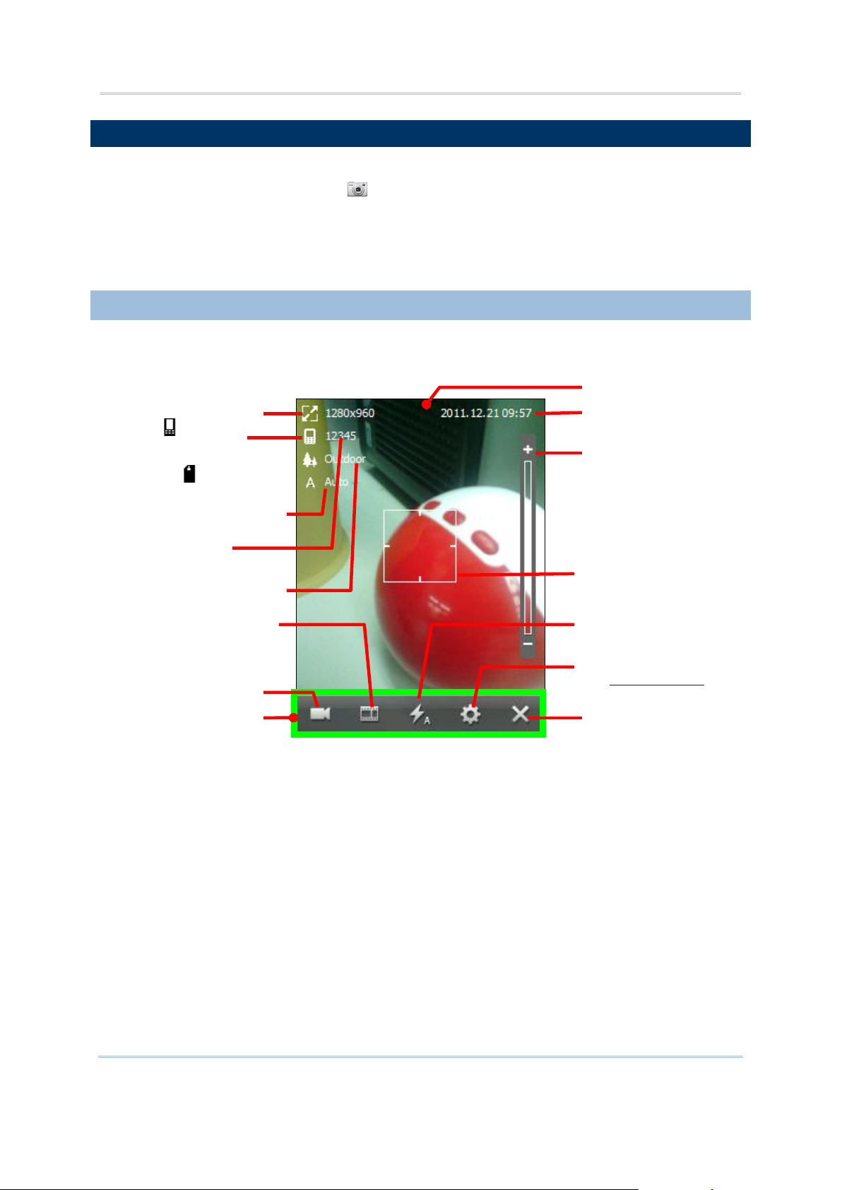
CP50 Mobile Computer Reference Manual
LAUNCH CAMERA
Focus area
Camera’s date & time
Zoom Control:
Tap +/- to zoom out/in on the
subject.
Closes camera
Switches to Camcorder
Image size of the picture to take
Remaining capacity: Amount of
pictures to be taken
Current scene mode
Current white balance
Camera application
Opens Pictures & Videos
Turns on/off flash or leaves it
on automatic
Accesses camera settings.
See Camera Settings
“Save-to” icon. means the
picture to take is to save to the
mobile computer’s internal storage;
or an SD card icon displays
here.
Menu bar
To launch the camera:
1) On Start screen, tap Camera .
OR
1) Simply press the physical camera shutter button.
Camera opens in landscape mode and readies to take pictures.
CAMERA SCREEN
Camera opens showing subject area on the screen with a few pieces of status info at the
upper-left and date/time info at the upper-right.
76
Page 91

Camera
TAKE PICTURES
Camera application is working
on the picture
When the framed subject gets
in focus, the focus indicator
changes color.
By default, pictures are taken with JPEG format and saves to the mobile computer’s internal
storage at My Device\My Documents\My Pictures. To change the default, see Camera
Settings.
To take a picture:
1) Turn on camera as described in Launch Camera.
Camera opens in landscape mode and readies to take pictures.
In case menu bar doesn’t show an icon but an icon, tap icon to switch to
camera.
2) Adjust the flash, picture quality and any other settings if you want to, or leave them on
automatic. Tap icon on menu bar to configure camera. See Camera Settings.
3) Frame your object on the screen.
4) Press physical shutter button. (See Overview.)
Camera proceeds to bring the subject into focus. Once it gets in focus, the focus
indicator changes color and the camera takes a picture. A rotating icon shows
onscreen indicating the application is working on the picture.
77
Page 92

CP50 Mobile Computer Reference Manual
If preview screen is enabled, the picture you just took displays for a moment for preview.
Icon
Description
Closes camera.
Opens camera settings:
Sets where to store the picture to take. Options are:
: the mobile computer’s internal storage (at My Device\My
Documents\My Pictures by default)
: the external storage i.e. the SD card (at My Device\Storage
Card\DCIM\100CIPHR by default).
Sets image size (pixels) for the picture to take. Options are:
320 x 240
640 x 480
1280 x 960
Goes back to camera screen
Picture preview
Emails currently previewed
picture
Discards currently
previewed picture
Currently previewed picture size
Remaining capacity: Amount of
pictures to be taken
“Save-to” icon. means
currently previewed picture is to
save to the mobile computer’s
internal storage; or a SD card icon
displays here.
Tap to email the picture by the mobile computer’s data connections or tap to
discard it.
CAMERA SETTINGS
Although the camera is a point-and-shoot type with automatic settings for quick shooting of
photographs, it supports changing sharpness, contrast, white balance and so on, and it
supports shooting negatives and pictures with other special effects. It even supports GPS
tags.
At the bottom of camera screen is camera’s menu bar . It bears a few
icons that tweak the camera. Tap icon to access camera settings.
The table below details this menu bar:
78
Page 93

Camera
1600 x 1200
2048 x 1536
2592 x 1944
Sets quality for the picture to take. Options are:
High
Medium
Affixes date/time stamps to the picture to take. Date/time stamps are fixed at the
upper-right of pictures.
Enables/disables previewing the picture to take, and sets how long to preview it.
Options are:
3 sec
5 sec
10 sec
Enables/Disables GPS tag for a picture to take.
Enables/disables taking a picture some time after shutter button is pressed. Helpful
for cases like self-portraits. Options are:
3 sec
5 sec
10 sec
Applies a special effect to the picture to take. Options are:
Monochrome
Sepia
Negative
Sets White Balance for the picture to take. Options are:
Auto: Leaves White Balance on automatic
Fluorescent
Tungsten
Daylight
Cloudy
Sets a scene mode for the picture to take. Options are:
Outdoor
Indoor lowlight
Adjusts brightness, contrast and sharpness for the pictures to take.
Sets if camera discharges a flash of light for the picture to take. Options are:
Auto:
The default, which leaves the flash up to camera’s decision according to its
light meter.
On:
The flash is on for all shots.
Off:
The flash is off for all shots.
Opens Pictures & Videos folder where pictures and videos can be viewed, edited and
output.
Switches camera to camcorder.
79
Page 94

CP50 Mobile Computer Reference Manual
LAUNCH CAMCORDER
Closes camcorder
Enables/mutes audio
Image size of the video to shoot
Remaining capacity (duration
of the video to be shot)
Camcorder launches and
shows subject area
onscreen
Switches to camera
Opens Pictures & Videos
“Save-to” icon. means the video
to shoot is to save to the mobile
computer’s internal storage; or a SD
card icon displays.
Date/time info
Menu bar
1) Launch camera as described in Launch Camera.
Normally camera opens in landscape mode and readies to take pictures rather than
shooting video so when it opens you have an icon on menu bar.
2) Tap icon to switch the application to camcorder.
If menu bar shows an icon, the application is camcorder already and you can skip
this step.
Camcorder launches.
CAMCORDER SCREEN
Camcorder launches showing subject area onscreen with a few status info at the upper-left
and date/time info at the upper-right.
80
Page 95

Camera
SHOOT VIDEOS
Date/time info
Closes camcorder
Enables/mutes audio
Image size of currently shot
video
Remaining capacity: Duration
of the video to be shot
In-shoot screen
Switches to camera
Opens Pictures & Videos
By default, videos are shot in WMV format and saves to the mobile computer’s internal
storage at My Device\My Documents\My Pictures. To change the default, see Camera
Settings.
To shoot a video:
1) Launch camcorder as described in Launch Camcorder.
Camcorder launches and shows subject area onscreen.
2) Point the lens and frame the scene where you want to start.
3) Hit physical shutter button. (See also Overview.)
Camcorder starts to shoot the video. It displays a screen such as below:
4) Hit physical shutter button again to stop shooting.
A rotating icon shows onscreen indicating the application is working on the video.
81
Page 96

CP50 Mobile Computer Reference Manual
If preview is enabled, once the video is worked out, a preview screen shows the very first
Icon
Description
Closes camcorder.
Enables/mutes audio.
Opens Pictures & Videos where pictures and videos can be viewed, edited and output.
Switches to camera.
Video preview
Emails currently
previewed video
Discards currently
previewed video
Currently previewed video’s image size
Remaining capacity: Duration
of videos to be shot
“Save-to” icon. means currently
previewed video is to save to the
mobile computer’s internal storage;
or a SD card graphic displays.
Goes back to camcorder screen
Enables/mutes audio
image of the video for a moment. Tap to email the video by the mobile computer’s
data connections or tap to discard it.
CAMCORDER SETTINGS
Camcorder shoots negative videos and videos with other special effects. Audio is also
supported.
Launch camcorder as described in Launch Camcorder. Tweak camcorder by the menu bar it
featured - .
Camcorder’s menu bar:
82
Page 97

Camera
Camcorder is supported by some camera settings. These settings should be made on
Menu Icon
Description
Sets where to store the video to shoot. Options are:
: the mobile computer’s internal storage (at My Device\My
Documents\My Pictures by default)
: the external storage i.e. the SD card (at My Device\Storage
Card\DCIM\100CIPHR by default).
Enables/disables previewing the video to shoot, and sets how long to preview it.
Options are:
3 sec
5 sec
10 sec
Applies a special effect to the video to shoot. Options are:
Monochrome
Sepia
Negative
camera’s menu bar.
83
Page 98

CP50 Mobile Computer Reference Manual
PICTURES & VIDEOS
Minimizes the application
Opens application’s option
menu
Pictures & Videos
Opens camera
The application opens
folder My Device\My
Documents\My
Pictures by default
Sorts files by other orders
Tap a picture to view it. Tap &
hold it to edit it, manage it or
take other actions to it.
Tap a video to play it. Tap &
hold it to edit it, manage it or
take other actions to it.
Opens onscreen keyboard
Browses for other files on the
mobile computer
Pictures & Videos is an application that views and edits the pictures taken and videos shoot,
or those copied or downloaded. It also sets background for Today Screen and Start Screen,
and sets avatars for your contacts. It also emails pictures and videos.
LAUNCH PICTURES & VIDEOS
To launch Pictures & Videos:
1) On Start screen, tap Pictures & Videos icon .
OR
Tap icon on camera or camcorder menu bar if it is active at the moment.
Pictures & Videos opens unfolding My Device\My Documents\My Pictures, the
default folder that stores the pictures and videos copied/downloaded from external
resources or took/shot on the mobile computer. Each picture and video therein displays
in thumbnail.
VIEW A PICTURE OR VIDEO
To view a picture or video:
1) Open Pictures & Video as described in Launch Pictures & Videos.
Pictures & Videos opens.
2) Tap the thumbnail of the picture or video to view.
84
Page 99

Camera
The picture displays or the video starts to play onscreen.
TAKE OTHER ACTIONS TO A VIDEO OR A PICTURE
To edit, manage or take other actions to a video or picture:
1) Open Pictures & Video as described in Launch Pictures & Videos.
Pictures & Videos opens.
2) Tap & hold the thumbnail of the picture or video to edit, manage or take other actions to.
A context menu comes up.
3) Tap a menu item to perform the desired action.
OR
2) Tap the thumbnail of the prospective picture or video.
It becomes selected with highlight.
3) Tap the command button that comes up on Softkey bar.
85
Page 100

CP50 Mobile Computer Reference Manual
86
 Loading...