

Page 1

1504B Barcode Scanner
Setup barcodes included.
Version 1.00
Page 2

Copyright © 2017 CIPHERLAB CO., LTD.
All rights reserved
The software contains proprietary information of CIPHERLAB CO., LTD.; it is provided
under a license agreement containing restrictions on use and disclosure and is also
protected by copyright law. Reverse engineering of the software is prohibited.
Due to continued product development this information may change without notice. Th e
information and intellectual property contained herein is confidential between CIPHERLAB
and the client and rem ains the exclusive property of CIPHERLAB CO., LTD. If finding any
problems i n the documentation, please rep ort them to us in writing. CIPHERLAB d oes
not warrant that this document is error-free.
No part of this publication may be reproduced, stored in a retrieval system, or
transmitted in any form or by any means, electronic, mechanical, photocopying,
recording or otherwise without the prior written permission of CIPHERLAB CO., LTD.
For product consultancy and technical support, please contact the local sales
representative. Alternatively, visit our web site for more information.
The CipherLab logo is a registered trademark of CIPHERLAB CO., LTD.
All brand, product and service, and trademark names are the property of their registered
owners.
The editorial use of these names is for identification as well as to the benefit of the
owners, with no intent io n of infringement.
CIPHERLAB CO., LTD.
Website: http://www.cipherlab.com
Page 3

FOR USA
FOR CANADA
IMPORTANT NOTICES
This equipment has been tested and found to comply with the limits for a Class B digital
device, pursuant to Part 15 of the FCC Rules. These limits are designed to provide
reasonable protection against harmful interference in a residential installation. This
equipment generates, uses and c an radiate radio freq uency energy and , if not installed
and used in accordance with the instructions, may cause harmful interference to radio
communications. However, there is no guarantee that interference will not occur in a
particular installation. If this equipment does cause harmful interference to radio or
television reception, which can be determined by turning the equipment off and on, the
user is encouraged to try to correct the interference by one or more of the following
measures:
Reorient or relocate the receiving antenna.
Increase the separation between the equipment and receiver.
Connect the equipment into an outlet on a circuit different from that to which the
receiver is connected.
Consult the dealer or an experienced radio/TV technician for help.
This device complies with Part 15 of the FCC Rules. Operation is subject to the following
two conditions: (1) This device may not cause harmful interference, and (2) this device
must accept any interferenc e received, incl uding interferenc e that may caus e undesired
operation.
This digital apparatus does not exceed the Class B limits for radio noise emissions from
digital apparatus as set out in the interference-causing equipment standard entitled
"Digital Apparatus," ICES-003 of Industry Canada.
This device complies with Part 15 of the FCC Rules. Operation is subject to the following
two conditions: (1) This device may not cause harmful interference, and (2) this device
must accept any interferenc e received, incl uding interferenc e that may caus e undesired
operation.
Cet appareil numerique respecte les limites de bruits radioelectriques applicables aux
appareils numeriques de Classe B prescrites dans la norme sur le material brouilleur:
"Appareils Numeriques," NMB-003 edictee par l'Industrie.
Page 4

FOR PRODUCT WITH LASER
SAFETY PRECAUTIONS
CARE & MAINTENANCE
CAUTION
This laser c omp one nt em its FD A / IEC C las s 2 la ser lig ht at the exit port . Do not
stare into beam.
DO NOT expose the scanner to any flammable sources.
Under no circumstances, internal components are self-serviceable.
For AC power adaptor, a socket outlet shall be installed near the equipment and shall
be easily accessible. Make sure there is stable power supply for the scanner or its
peripherals to operate properly.
Use a clean cloth to wipe dust off the scanning window and the body of the scanner.
DO NOT use/mix any bleach or cleaner.
K eep the scanner awa y from any magnet s and magnetic fi elds to prevent th e laser
engine from malfunctioning.
If finding the scanner malfunctioning, write down the specific scenario and consult the
local sales representative.
Page 5

Version
Date
Notes
same 1D symbologies as
(GS1 DataBar security level) to
RELEASE NOTES
1.00 Mar. 13, 2017
Modified: 1504B models added (bas ed on 1504 Series User Guide)
Modified: Symbologies Supported –
1500P
Modified: Symbology Supported – Code 11 added
Removed: 1.6.1 Test Mode s
Modified: 1.9 – Three times redundancy read barcode added
Modified: 1.10 – Addon Security level 2~30; defa ult 2
Modified: 1.11 – behavior of 1504B same as 1504A
Removed: 1.12 Negati v e Barcodes
Removed: 1.16 Illumination Brightness
Modified: 3.1 ~ 3.19 – same 1D symbologies as 1500P
Modified: 3.1.1 – set “Normal” (Codebar security level) to defa ult
New: 3.1.5 Code Length Qualification – (Codebar)
Modified: 3.5.5 – set “Normal” (Code 39 security level) to default
New: 3.5.6 Asterisks as Data Characters
New: 3.5.7 Code Length Qualification – (Code 39)
New: 3.6.1 Code Length Qualification – (Code 93)
Modified: 3.7.1 – set “Normal” (Code 128 security level) to default
New: 3.9.1 EAN-13 Addon Modes
Modified: 3.9.4 – set “Normal” (EAN-13 security level) to default
Modified: 3.11.1 – ISBT concatenation default is disabled
Modified: 3.16.8 – set “Normal”
default
New: 3.20 Code 11
Modified: 3.21 – Maxicode, Aztec removed
Modified: 3.21.3 – GS1 formatting removed
Modified: 3.21.3 – Data Matrix Inverse added
Modified: 3.21.4 – GS1 formatting removed
Modified: 3.21.4 – QR Code Mirror/Inverse added
Modified: 3.21.5 – MicroQR default is disabled
Removed: 3.22 Macro PDF
Modified: 4.2.2 – same 1D symbologies as 1500P
Modified: 4.2.2 – Code 11 added
Modified: 4.4.1 – same 1D symbologies as 1500P
Modified: 4.4.1 Select Pre-defined Code ID – AIM Code ID added
Modified: 4.4.2 – same 1D symbologies as 1500P
Modified: 4.4.2 Change Code ID – Code 11 added
Page 6

Modified: 4.5 Length Code – Code 11 added
Modified: 4.5 – same 1D symbologies as 1500P
Modified: 4.6.1 – same 1D symbologies as 1500P
Modified: 4.6.1 – Code 11 added
Modified: 5.3 – same 1D symbologies as 1500P
Modified: 5.3.1 Appli c a ble Code Type – Code 11 added
New: Appendix VI Keyboard Type One-Scan Barcode
Page 7

CONTENTS
........................................................................................................ - 3 -
.................................................................................................................... - 5 -
........................................................................................................................ 1
............................................................................................................................. 5
............................................................ 17
IMPORTANT NOTICES
For USA........................................................................................................................................ - 3 -
For Canada ................................................................................................................................. - 3 -
For Product with Laser ........................................................................................................... - 4 -
Safety Precautions .................................................................................................................. - 4 -
Care & Maintenance................................................................................................................ - 4 -
RELEASE NOTES
INTRODUCTION
Inside the Package ...................................................................................................................... 2
Product Highlights ....................................................................................................................... 2
Symbologies Supported ............................................................................................................ 3
QUICK START
Enter Configuration Mode ......................................................................................................... 6
Exit Configuration Mode ............................................................................................................ 6
Default Settings ........................................................................................................................... 7
Save User Settings as Defaults ......................................................................................... 7
Restore User Defaults ........................................................................................................... 7
Restore System Defau lts ..................................................................................................... 7
Read a Setup Barcode ............................................................................................................... 8
Configure Parameters ........................................................................................................... 8
List the Current Settings ................................................................................................... 12
Create One-Scan Setup Barcodes ....................................................................................... 14
1D One-Scan Barcode ........................................................................................................ 14
2D One-Scan Barcode ........................................................................................................ 15
UNDERSTANDING THE BARCODE SCANNER
1.1 Power-On .............................................................................................................................. 18
1.2 Transmit Buffer................................................................................................................... 18
1.3 LED Indicator ....................................................................................................................... 19
1.3.1 Good Read LED .......................................................................................................... 19
1.3.2 Good Read LED Duration ....................................................................................... 19
1.4 Beeper .................................................................................................................................... 20
1.4.1 Beeper Volume .......................................................................................................... 20
1.4.2 Good Read Beep ....................................................................................................... 21
1.5 Send “NR” to Host ............................................................................................................. 22
1.6 Scan Modes .......................................................................................................................... 23
1.6.1 Laser Mode .................................................................................................................. 24
Page 8

1504B Barcode Scanner User Guide
1.6.2 Auto Off Mode ............................................................................................................ 24
................................................................................... 35
1.6.3 Auto Power Off Mode .............................................................................................. 24
1.6.4 Aiming Mode ............................................................................................................... 25
1.6.5 Multi-Barcode Mode ................................................................................................. 25
1.6.6 Presentation Mode .................................................................................................... 26
1.7 Scanning Timeout .............................................................................................................. 27
1.8 Delay between Re-read ................................................................................................... 28
1.9 Read Redundancy (1D) ................................................................................................... 29
1.10 Addon Security for UPC/EAN Barcodes ................................................................... 30
1.11 Auto-Sense Mode ............................................................................................................ 31
1.12 Cable Auto-Detection ..................................................................................................... 32
1.13 Picklist Mode ..................................................................................................................... 33
1.14 Mobile Phone/Display Mode ........................................................................................ 34
SELECTING OUTPUT INTERFACE
2.1 Keyboard Wedge ................................................................................................................ 36
2.1.1 Activate Keyboard Wedge & Select Keyboard Type .................................... 37
2.1.2 Keyboard Settings .................................................................................................... 38
2.1.3 Inter-Character Delay ............................................................................................. 44
2.1.4 Inter-Function Delay ............................................................................................... 45
2.1.5 Special Keyboard Feature ..................................................................................... 45
2.2 RS-232 ................................................................................................................................... 46
2.2.1 Activate RS-232 Interface ..................................................................................... 46
2.2.2 Baud Rate .................................................................................................................... 46
2.2.3 Data Bits ...................................................................................................................... 47
2.2.4 Parity ............................................................................................................................. 47
2.2.5 Stop Bit ......................................................................................................................... 47
2.2.6 Flow Control ................................................................................................................ 48
2.2.7 Inter-Character Delay ............................................................................................. 49
2.2.8 Inter-Function Delay ............................................................................................... 49
2.2.9 ACK/NAK Timeout .................................................................................................... 50
2.3 Direct USB HID ................................................................................................................... 51
2.3.1 Activate USB HID & Select Keyboard Type .................................................... 51
2.3.2 Keyboard Settings .................................................................................................... 52
2.3.3 Inter-Character Delay ............................................................................................. 58
2.3.4 Inter-Function Delay ............................................................................................... 58
2.3.5 HID Character Transmit Mode ............................................................................. 59
2.3.6 Special Keyboard Feature ..................................................................................... 59
2.4 Direct USB VCOM ............................................................................................................... 60
2.4.1 Activate USB Virtual COM...................................................................................... 60
2.4.2 Inter-Function Delay ............................................................................................... 60
2.4.3 ACK/NAK Timeout .................................................................................................... 61
2.5 Direct USB VCOM_CDC.................................................................................................... 62
2.5.1 Activate USB VCOM_CDC ...................................................................................... 62
2.5.2 Inter-Function Delay ............................................................................................... 62
2.5.3 ACK/NAK Timeout .................................................................................................... 63
Page 9

1504B Barcode Scanner User Guide
CHANGING SYMBOLOGY SETTINGS
............................................................................. 65
3.1 Codabar ................................................................................................................................. 66
3.1.1 Security Level ............................................................................................................ 66
3.1.2 Start/Stop Transmission ........................................................................................ 66
3.1.3 Start/Stop Character Selection ........................................................................... 67
3.1.4 CLSI Conversion ........................................................................................................ 67
3.1.5 Code Length Qualification ..................................................................................... 68
3.2 Code 25 – Industrial 25 .................................................................................................. 69
3.2.1 Select Start/Stop Pattern ...................................................................................... 69
3.2.2 Verify Check Digit ..................................................................................................... 69
3.2.3 Transmit Check Digit ............................................................................................... 70
3.2.4 Code Length Qualification ..................................................................................... 70
3.3 Code 25 – Interleaved 25 .............................................................................................. 72
3.3.1 Select Start/Stop Pattern ...................................................................................... 72
3.3.2 Verify Check Digit ..................................................................................................... 72
3.3.3 Transmit Check Digit ............................................................................................... 73
3.3.4 Code Length Qualification ..................................................................................... 73
3.4 Code 25 – Matrix 25 ......................................................................................................... 75
3.4.1 Select Start/Stop Pattern ...................................................................................... 75
3.4.2 Verify Check Digit ..................................................................................................... 75
3.4.3 Transmit Check Digit ............................................................................................... 76
3.4.4 Code Length Qualification ..................................................................................... 77
3.5 Code 39 ................................................................................................................................. 78
3.5.1 Transmit Start/Stop Characters .......................................................................... 78
3.5.2 Verify Check Digit ..................................................................................................... 78
3.5.3 Transmit Check Digit ............................................................................................... 79
3.5.4 Standard/Full ASCII Code 39 ............................................................................... 79
3.5.5 Security Level ............................................................................................................ 79
3.5.6 Asterisks (*) as data Characters ........................................................................ 80
3.5.7 Code Length Qualification ..................................................................................... 80
3.6 Code 93 ................................................................................................................................. 81
3.6.1 Code Length Qualification ..................................................................................... 81
3.7 Code 128 ............................................................................................................................... 83
3.7.1 Security Level ............................................................................................................ 83
3.8 EAN-8 ..................................................................................................................................... 84
3.8.1 Convert to EAN-13 ................................................................................................... 84
3.8.2 Transmit Check Digit ............................................................................................... 85
3.8.3 Conversion Format ................................................................................................... 85
3.9 EAN-13 ................................................................................................................................... 86
3.9.1 EAN-13 Addon Modes ............................................................................................. 87
3.9.2 Convert to ISBN ........................................................................................................ 89
3.9.3 Convert to ISSN ........................................................................................................ 89
3.9.4 Transmit Check Digit ............................................................................................... 90
3.9.5 Security Level ............................................................................................................ 90
3.10 GS1-128 (EAN-128) ....................................................................................................... 91
3.10.1 Transmit Code ID ................................................................................................... 91
Page 10

1504B Barcode Scanner User Guide
3.10.2 Field Separator (GS Character) ........................................................................ 91
3.10.3 GS1 Formatting ...................................................................................................... 92
3.10.4 Application ID Mark ............................................................................................... 92
3.11 ISBT 128 ............................................................................................................................. 93
3.11.1 ISBT Concatenation .............................................................................................. 93
3.12 MSI ....................................................................................................................................... 94
3.12.1 Verify Check Digit .................................................................................................. 94
3.12.2 Transmit Check Digit ............................................................................................ 94
3.12.3 Code Length Qualification ................................................................................... 95
3.13 French Pharmacode ........................................................................................................ 96
3.13.1 Transmit Check Digit ............................................................................................ 96
3.14 Italian Pharmacode ........................................................................................................ 96
3.14.1 Transmit Check Digit ............................................................................................ 96
3.15 Plessey ................................................................................................................................ 97
3.15.1 Convert to UK Plessey .......................................................................................... 97
3.15.2 Transmit Check Digit ............................................................................................ 97
3.16 GS1 DataBar (RSS Family) ......................................................................................... 98
3.16.1 Select Code ID ........................................................................................................ 98
3.16.2 GS1 DataBar Omnidirectional (RSS-14) ....................................................... 99
3.16.3 GS1 DataBar Expanded (RSS Expanded) ................................................... 100
3.16.4 GS1 DataBar Limited (RSS Limited) ............................................................. 101
3.16.5 Field Separator (GS Character) ...................................................................... 102
3.16.6 GS1 Formatting .................................................................................................... 102
3.16.7 Application ID Mark ............................................................................................. 102
3.16.8 GS1 DataBar Security Level ............................................................................ 103
3.17 Telepen .............................................................................................................................. 103
3.17.1 Telepen Output ASCII/Numeric ...................................................................... 104
3.18 UPC-A ................................................................................................................................. 105
3.18.1 Convert to EAN-13 .............................................................................................. 106
3.18.2 Transmit System Number ................................................................................. 106
3.18.3 Transmit Check Digit .......................................................................................... 106
3.19 UPC-E ................................................................................................................................. 107
3.19.1 Select System Number ...................................................................................... 108
3.19.2 Convert to UPC-A ................................................................................................. 108
3.19.3 Transmit System Number ................................................................................. 109
3.19.4 Transmit Check Digit .......................................................................................... 109
3.20 Code 11 ............................................................................................................................. 109
3.20.1 Verify Check Digit ................................................................................................ 109
3.20.2 Transmit Check Digit .......................................................................................... 110
3.20.3 Security Level ........................................................................................................ 110
3.20.4 Code Length Qualification ................................................................................. 111
3.21 2D Symbologies ............................................................................................................. 112
3.21.1 PDF417 ..................................................................................................................... 112
3.21.2 MicroPDF417 .......................................................................................................... 112
3.21.3 Data Matrix ............................................................................................................. 112
3.21.4 QR Code ................................................................................................................... 113
Page 11

1504B Barcode Scanner User Guide
3.21.5 MicroQR .................................................................................................................... 114
.......................................................................................... 115
.............................................................. 143
................................................................................................................. 171
........................................................................................................ 173
DEFINING OUTPUT FORMAT
4.1 Letter Case ......................................................................................................................... 115
4.2 Character Substitution ................................................................................................... 116
4.2.1 Select a Set for Character Substituion ........................................................... 117
4.2.2 Symbologies for Character Substitution (All 3 Sets) ................................ 118
4.3 Prefix/Suffix Code ............................................................................................................ 125
4.4 Code ID ................................................................................................................................ 126
4.4.1 Select Pre-defined Code ID ................................................................................ 126
4.4.2 Change Code ID ...................................................................................................... 130
4.4.3 Clear Code ID Settings ......................................................................................... 132
4.5 Length Code ....................................................................................................................... 133
4.6 Multi-Barcode Editor ....................................................................................................... 138
4.6.1 Edit a Concatenation of Barcodes .................................................................... 139
4.6.2 Activate the Concatenation of Barcodes ........................................................ 141
4.7 Removal of Special Character ..................................................................................... 142
APPLYING FORMATS FOR DATA EDITING
5.1 Activating Editing Formats ........................................................................................... 144
5.1.1 Activate Editing Formats ...................................................................................... 144
5.1.2 Exclusive Data Editing .......................................................................................... 145
5.2 How to Configure Editing Formats ............................................................................ 146
5.2.1 Select Format to Configure ................................................................................. 147
5.2.2 Restore Default Format ........................................................................................ 148
5.3 Configuring Format — Define Data Criteria .......................................................... 149
5.3.1 Applicable Code Type ............................................................................................ 149
5.3.2 Data Length .............................................................................................................. 156
5.3.3 Matching String & Location ................................................................................. 157
5.4 Configuring Format — Define Data Field ................................................................ 158
5.4.1 Start Position ............................................................................................................ 158
5.4.2 Field Adjustment ..................................................................................................... 158
5.4.3 Total Number of Fields ......................................................................................... 159
5.4.4 Field Settings............................................................................................................ 160
5.4.5 Pause Field Setting ................................................................................................ 166
5.5 Configuring Format — Define Transmission Sequence ..................................... 167
5.6 Programming Examples ................................................................................................ 169
5.6.1 Example I .................................................................................................................. 169
5.6.2 Example II ................................................................................................................. 170
SPECIFICATIONS
FIRMWARE UPGRADE
Using RS-232 ............................................................................................................................ 173
Using USB Virtual COM .......................................................................................................... 175
Page 12

1504B Barcode Scanner User Guide
HOST SERIAL COMMANDS
.............................................................................................. 177
.............................................................................................. 179
............................................................................................................ 183
......................................................................................... 187
.................................................................... 197
Serial Commands .................................................................................................................... 177
Example ....................................................................................................................................... 178
KEYBOARD WEDGE TABLE
Key Type & Status ................................................................................................................... 181
Key Type ................................................................................................................................ 181
Key Status ............................................................................................................................. 181
Example ....................................................................................................................................... 182
NUMERAL SYSTEMS
Decimal System ....................................................................................................................... 183
Hexadecimal System .............................................................................................................. 184
ASCII Table ................................................................................................................................ 185
READING DRIVER LICENSES
License Parsing Setup ............................................................................................................ 187
File Type ................................................................................................................................. 187
Output Sequence Setup ........................................................................................................ 188
Separators and Fields ............................................................................................................ 194
Edit Separators .................................................................................................................... 195
Edit Fields .............................................................................................................................. 196
KEYBOARD TYPE ONE-SCAN BARCODE
Keyboard Wedge ...................................................................................................................... 197
Direct USB HID ......................................................................................................................... 201
Page 13

The small-form-factor Barcode Scanners are capable of reading 2D barcodes. The
INTRODUCTION
tethered han dheld scanners are designed to help accelerate producti vity while loweri ng
the total cost of ownership. Intensive data collection jobs are made easier with fast,
accurate barcode scanning in various working environments, especially in small
businesses. A new ordering option is provided for adapting a 2D scan engine to read both
1D and 2D barcodes.
Owing to th e slim, ergonomic design, extremely low power consumption, and powerful
decoding capability, CipherLab Barcode Scanners are the best choice for the following
applications –
Receiving in Retail
Product labeling & Tracking
Shelf Product Replenishment
Mobile Point of Sale (POS)
Mobile Inventory Management
Order Picking & Staging
Work-In-Process Tracking
Material Flow Control
Transportation & Distribution
Warehousing
Asset Management
This manual contains information on operating the scanner and using its features. It is
better to keep one copy of the manual at hand for quick reference or maintenance
purposes. To avoid any improper disposal or operation, please read the manual
thoroughly before use.
Thank you for choos ing C ipherLab products!
1
Update
Page 14

1504B Barcode Scanner User Guide
INSIDE THE PACKAGE
PRODUCT HIGHLIGHTS
The items included in the package may be di fferent , dep endin g on order . Rich choice s of
output interfaces are available to enhance the total performance of the scanner. Refer to
product specifi ca ti on s.
Save the box and packaging material for future use in case it is need to store or ship the
scanner.
Barcode Scanner: 1504B
Small-form-factor and built tough to survive drop test
Extremely low power consumption
Firmware upgradeable
Supports most popular barcode symbologies, including GS1-128 (EAN-128), GS1
DataBar (RSS), etc.
Supports a variety of 2D symbologies
Supports different scan modes, including Aiming Mode and Multi-Barcode Mode
Note
User feedback via LED indicator and beeper
Beeping tone and duration programmable for Good Read
Provides choices of output interfaces, including RS-232, Keyboard Wedge, and USB.
Programmable parameters include data output format, editing format, symbologies,
etc.
Note: In any scan mode other than Multi-Barcode Mode, a barcode acceptable to the
scanner can only contain data of 7 KB at most.
2
Enter Setup
Page 15

Introduction
SYMBOLOGIES SUPPORTED
Symbologies Supported: Enable/Disable
Default
S1 DataBar
Most of the popular barcode symbologies are supported, as listed below. Each can be
individually enabled or disabled. The scanner will automatically discriminate and
recognize a ll the symbo logies tha t are enabl ed. Refer to Chapter 3
Settings for details of each symbology.
Codabar Enabled
Code 93 Enabled
MSI Disabled
Plessey Disabled
Telepen Disabled
Code 128 Code 128 Enabled
GS1-128 (EAN-128) Enabled
ISBT 128 Enabled
Code 2 of 5 Industrial 25 Enabled
Interleaved 25 Enabled
Matrix 25 Disabled
Changing Symbology
Code 3 of 9 Code 39 Enabled
Italian Pharmacode Disabled
French Pharmacode Disabled
EAN/UPC EAN-8 Enabled
EAN-8 Addon 2 Disabled
EAN-8 Addon 5 Disabled
EAN-13 Enabled
EAN-13 & UPC-A Addon 2 Disabled
EAN-13 & UPC-A Addon 5 Disabled
ISBN Disabled
UPC-E0 Enabled
UPC-E1 Disabled
UPC-E Addon 2 Disabled
UPC-E Addon 5 Disabled
UPC-A Enabled
Code 11 Disabled
G
(RSS)
GS1 DataBar Omnidirectional (RSS-14) Disabled
GS1 DataBar Truncated Disabled
3
Update
Page 16

1504B Barcode Scanner User Guide
GS1 DataBar Limited ( RSS Limited) Disabled
GS1 DataBar Expanded (RSS Ex pa nded) Disabled
2D
Symbologies
PDF417 Enabled
MicroPDF417 Disabled
Data Matrix Enabled
QR Code Enabled
MicroQR Disabled
4
Enter Setup
Page 17
The configuration of the scanner can be done by reading the setup barcodes contained in
QUICK START
this manual or via the ScanMaster software.
This section describes the procedure of configuring the scanner by reading the setup
barcodes and provides some examples for demonstration.
Note: If RS-232 or USB Virtual COM is selected f o r ou t p u t interface, the h ost can di rect ly
send serial commands to configure the scanner.
For example, run Hyp erTe rmin al.exe and t ype t he 6-digit command located under
each setup barcode. Refer to
Appendix II Host Serial Commands.
5
Update
Page 18

1504B Barcode Scanner User Guide
ENTER CONFIGURATION MODE
EXIT CONFIGURATION MODE
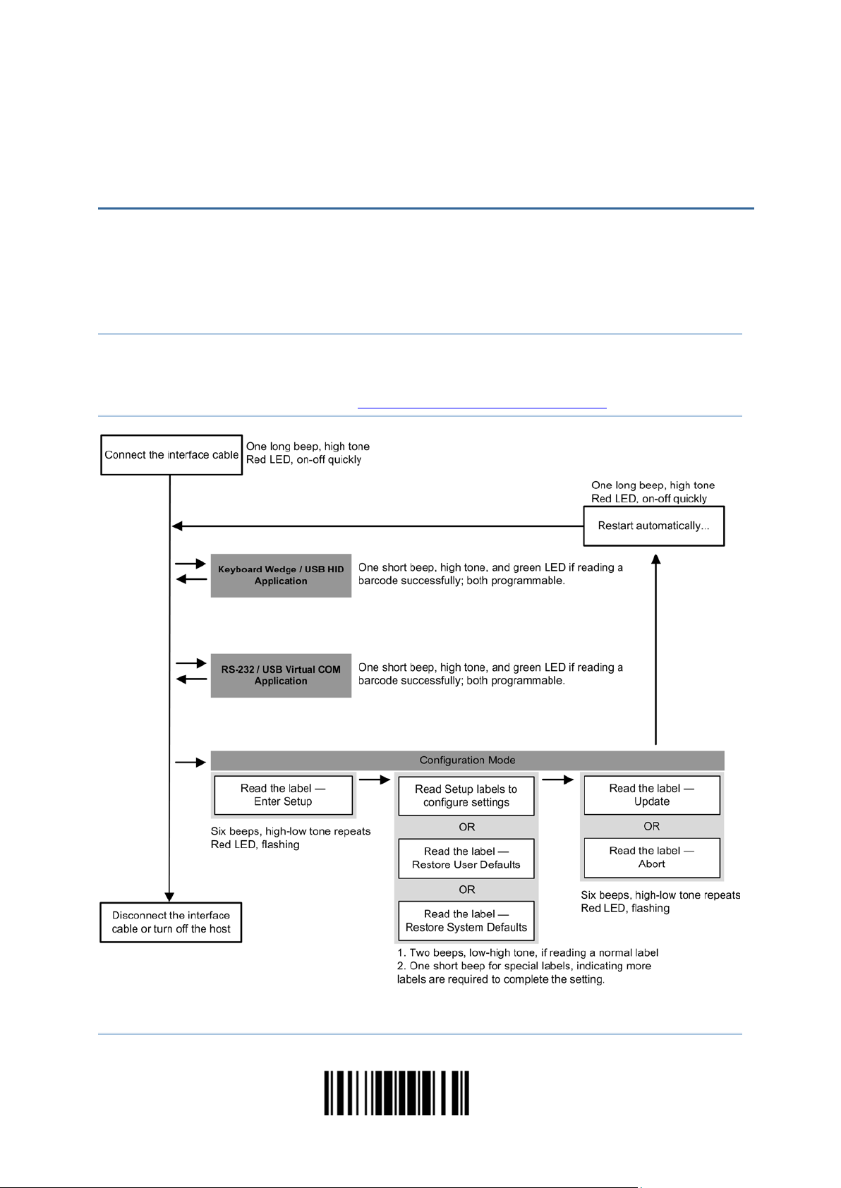
For the scann er to ente r the confi gurati on mode, have it read t he "Enter S etup" barcode
located at the bottom of almost every even page of this manual.
The scanner will respond with six beeps and its LED indicator will become flash ing red
after reading the barcode.
Enter Setup
For configuring scanner parameters, see “Read a Setup Barcode” below.
For the scanner to save settings and exit the configuration mode, have it read the
“Update” barcode located at the bottom of almost every odd page of this manual. To exi t
the configuration mode without saving any changes, have the scanner read the “Abort”
barcode instead.
Just li ke reading the “Enter Setup” barcode, the scann er will respon d with six beep s
and its LED indicator will become flashing red after reading the barcode. Wait for a
few seconds for the scanner to restart itself.
Update
Abort
6
Enter Setup
Page 19

Quick Start
DEFAULT SETTINGS
SAVE USER SETTINGS AS DEFAULTS
Save as User
RESTORE USER DEFAULTS
Restore User
RESTORE SYSTEM DEFAULTS
Restore System
For the scan ner to keep the customized settings as use r defau lts, have it read the “Save
as User Defaul ts” barcode. This is a normal setup ba rcode, and the scanner will respond
with two beeps (low-high tone).
After reading the “Update” barcode, the current settings will be saved as user
defaults.
Defaults
For the scan ner t o rest ore the user defaults saved ea rlier, have i t read the “Restore User
Defaults” barcode. This i s a normal setup barcode, and t he sca nn er wi ll r esp ond w it h t wo
beeps (low-high tone).
After reading the “Update” barcode, all the parameters o f the scanner will return to
their customized values.
Defaults
For the scanner to restore the factory defaults, have it read the “Restore System
Defaults” barcode. This i s a normal setup barcode, and the sca nn er wi ll resp on d wi t h t wo
beeps (low-high tone).
After reading the “Update” barcode, all the paramet ers of the scanner w ill return to
their default values.
Defaults
Note: The system default value (if there is) for each settin g is indicated by an asterisk
“*”.
7
Update
Page 20
1504B Barcode Scanner User Guide
READ A SETUP BARCODE
CONFIGURE PARAMETERS
For most of the scanner parameters, only one read is required to set them to new values.
The scanner will respond with two beeps (low-high tone) when each parameter is set
successfully.
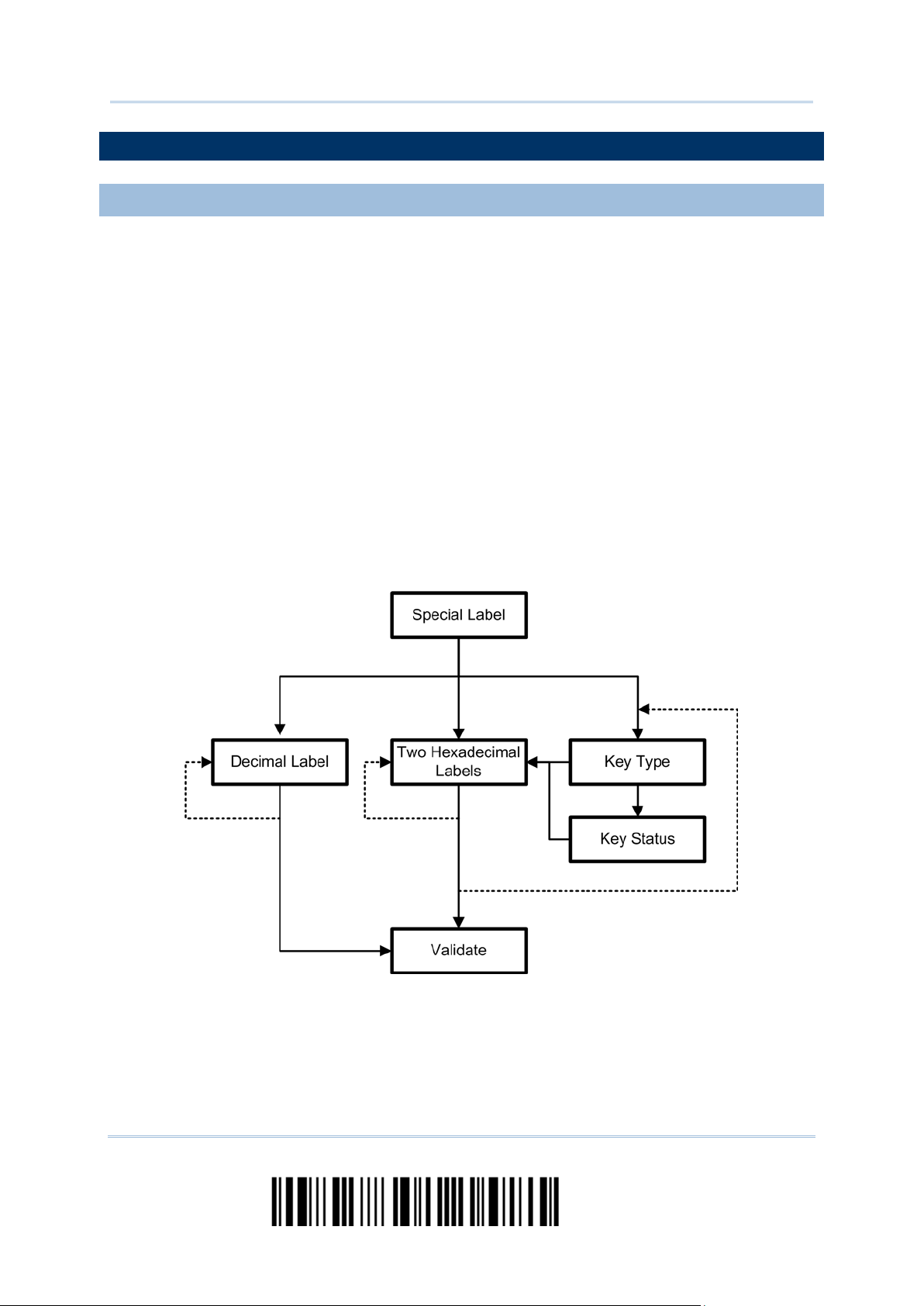
But for a number of special parameters, multiple reads are required to complete the
setting. In this case, the scanner will respond with a short beep to indicate it needs to
read more setu p barcodes. These special pa rameters may require re ading one or more
setup barcodes, such as
Numeric barcodes, say, for keyboard type, inter-character delay , lengt h qualification
Hexadecimal barcodes, say, for character strings as prefix, suffix, etc.
W hen “Keyboa rd Wedg e” or “USB HID” is con figu red for int erface, Key Type and Key
Status will then become applicable. Decide whether or n ot t o change key status when
“Normal Key” is selected for Key Type.
To complete the configuration of these special parameters, it requires reading the
“Validate” barcode, and the scanner will respond with two beeps (low-high tone) to
indicate the input values a re validated.
8
Enter Setup
Page 21
Quick Start
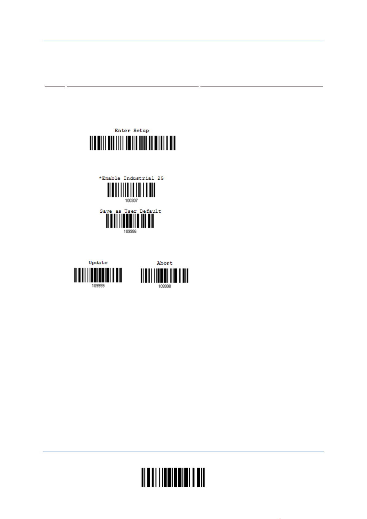
The example below shows how to save settings as “User Default” so that to restore u ser
Steps
Action
User Feedback if Successful
The scanner will respond with a long beep
and its LED indicator will
The scanner will respond with six beeps
, and
The scanner will respond with two beeps
normal setup
The scanner will respond with one long
defaults later:
1 Power on the scanner…
(high tone)
become solid red and go off qu ickly.
2 Enter the Conf ig uration Mode…
3 Read a Setup barcode…
For example,
(high-low tone repeats three times)
its LED indicator will be flashing red.
(low-high tone) if reading a
barcode.
4 Exit the Configuration Mode…
Same as for Enter the Configuration Mode.
OR
5 The scanner will automatically restart itself… Same as for Power on the scanner.
* When any configuration error occurs...
beep (low tone).
9
Update
Page 22
1504B Barcode Scanner User Guide
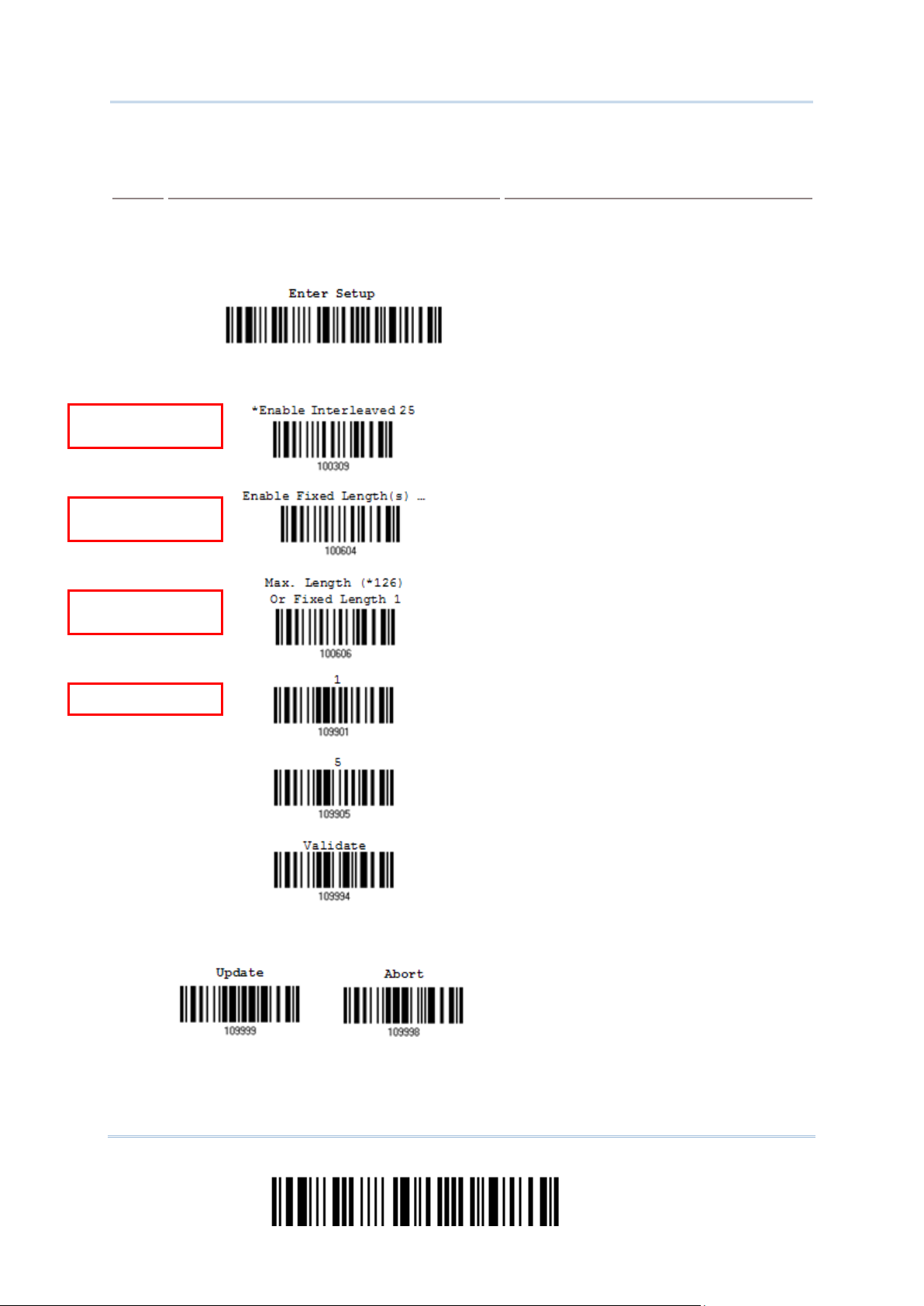
The example below shows how to set numeric parameters:
Steps
Action
User Feedback if Successful
The scanner will respond with a long beep
and its LED indicator will
The scanner will respond with six beeps
ow tone repeats three times), and
The scanner will respond with two beeps
normal setup
d with one short
, indicating the
“Decimal
The scanner will respond with two beeps
when the input val ues are
Normal setup
barcode
Normal setup
barcode
Special setup
barcode
Decimal barcodes
1 Power on the scanner...
(high tone)
become solid red and go off qu ickly.
2 Enter the Conf ig uration Mode…
(high-l
its LED indicator will become flashing red.
3 Read a Setup barcode...
For example,
(low-high tone) if reading a
barcode.
4 Exit the Configuration Mode…
The scanner will respon
beep if reading a special setup barcode
such as “Max. Length”
setup requires reading more barcodes.
Read the “Decimal Value” barcode(s).
Refer to Appendix IV
System”
(low-high tone)
validated.
Same as for Enter the Configuration Mode.
OR
5 The scanner will automatically restart itself… Same as for Power on the scanner.
10
Enter Setup
Page 23
Quick Start
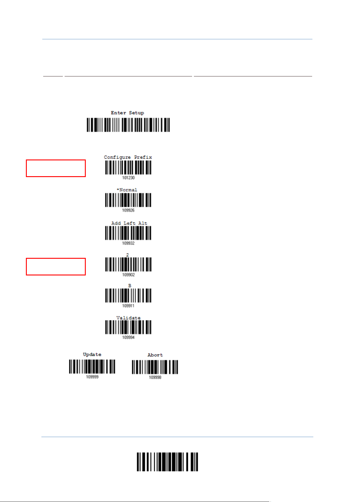
The example below shows how to set string parameters:
Steps
Action
User Feedback if Successful
The scanner will respond with a long beep
and its LED indicator will
l respond with six beeps
low tone repeats three times), and
The scanner will respond with one short
, indicating the setup
is
face, Key Type and Key
ecide
when
s
for the desired character string. For
example, read “2” and “B” for the scanner
Refer to Appendix IV “Hexadecimal
spond with two beeps
when the input val ues are
Special setup
barcodes
Hexadecimal
barcodes
1 Power on the scanner...
(high tone)
become solid red and go off qu ickly.
2 Enter the Conf ig uration Mode…
3 Read a Setup barcode...
For example,
The scanner wil
(highits LED indicator will become flashing red.
beep if reading a special setup barcode
such as “Prefix Code”
requires reading more barcodes.
When “Keyboar d Wedge” or “U SB HID”
configured for inter
Status will then become applicable. D
whether or not to change key status
“Normal Key” is selected for Key Type.
Refer to Appendix III
Read the “Hexadecimal Value” barcode
to prefix the char acter “+”.
System”
4 Exit the Configuration Mode…
OR
5 The scanner will automatically restart itself… Same as for Power on the scanner.
The scanner will re
(low-high tone)
validated.
Same as for Enter the Configuration Mode.
Update
11
Page 24

1504B Barcode Scanner User Guide
LIST THE CURRENT SETTINGS
Interface, Buzzer, and Other
settings regarding Prefix, Suffix, and
settings regarding: Readable Symbologies
settings regarding: Readable Symbologies
settings regarding Symbology Parameters
settings regarding Symbology Parameters
settings regarding Symbology Parameters
The current settings of all scan ner p aramet ers can be sent to the host computer for user
inspection. The listing includes pages as shown below. Select the page of interest by
having the scanner read the “List Page x” barcode. The scanner will respond with two
beeps (low-high tone) and send the selected page to the host immediately.
Lists settings regarding Firmware Version,
Serial Number,
Scanner Parameters
Lists settings regarding Prefix, Suffix, and
Length Code Setting (1/2)
Lists
Length Code Setting (2/2)
Lists settings regarding Code ID
List Page 1
List Page 2
List Page 3
List Page 4
Lists
(1/2)
Lists
(2/2)
Lists
(1/3)
Lists
(2/3)
Lists
(3/3)
Reserved
List Page 5
List Page 6
List Page 7
List Page 8
List Page 9
List Page 10
12
Enter Setup
Page 25

Quick Start
Lists settings regarding Editing Form a t 1
List Page 22
(1/2)
Lists settings regarding Editing Form a t 1
(2/2)
Lists settings regarding Editing Form a t 2
(1/2)
Lists settings regarding Editing Format 2
(2/2)
Lists settings regarding Editing Format 3
(1/2)
Lists settings regarding Editing Format 3
(2/2)
List Page 11
List Page 12
List Page 13
List Page 14
List Page 15
List Page 16
Lists settings regarding Editing Form a t 4
(1/2)
Lists settings regarding Editing Format 4
(2/2)
Lists settings regarding Editing Format 5
(1/2)
Lists settings regarding Editing Format 5
(2/2)
Lists settings of Driver License parsing
List Page 17
List Page 18
List Page 19
List Page 20
13
Update
Page 26

1504B Barcode Scanner User Guide
CREATE ONE-SCAN SETUP BARCODES
1D ONE-SCAN BARCODE
Scan Setup Barcode
The fact is mo st of t he scanne r para mete rs require only on e re ad for setting new valu es.
To facilitate configuring the scanner, create One-Scan setup barcodes for use.
The requirem en t s of a On e -Scan setup barcode are:
a prefix of the “#@” characters
the six digits of command parameters
a suffix of the “#”character
For example, the scanner needs reading three setup barcodes for the command
parameter “109952” to take effect:
Enter Setup
List Page 3
Update
Now, it requires only one read:
One-
for 109952
Note: The scanner will restart automatically upon reading the One-Scan setup barcode
for changing the interface. It will respond with a long beep and its LED will come
on-off shortly.
14
Enter Setup
Page 27
Quick Start
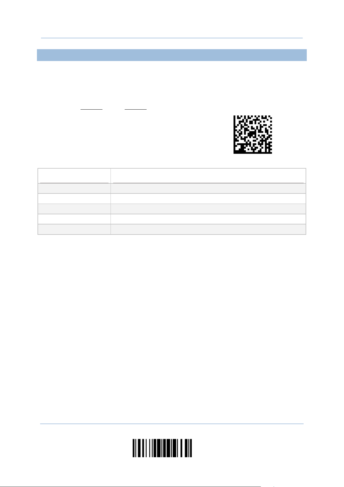
2D ONE-SCAN BARCODE
Command
Purpose
Users can also sc an a single 2D barcod e combining with a series of serial comman ds to
configure th e sca n n e r. For example, if you want t o ch a n g e the suffix ch a rac ter to ‘#’, you
will need to input the serial commands in sequence as follows (underlining the digits is to
make them more readable):
#@CipherLab101231109902109903109994
2D One-Scan Setup Barcode for configuring suffix
#@CipherLab Enter Setup
101231
109902 Give the first hexadecimal digi t of 0x23
109903
Configure suffix
Give the second hexadecimal digit of 0x23 for takin g ‘#’ as the suffix
109994 Validate the settings
15
Update
Page 28

1504B Barcode Scanner User Guide
16
Enter Setup
Page 29

This chapter explains the features and usage of the barcode scanner.
IN THIS CHAPTER
Chapter 1
UNDERSTANDING THE BARCODE SCANNER
1.1 Power-On ................................................................... 18
1.2 Transmit Buffer........................................................... 18
1.3 LED Indicator ............................................................. 19
1.4 Beeper....................................................................... 20
1.5 Send “NR” to Host ....................................................... 22
1.6 Scan Modes ................................................................ 23
1.7 Scanning Timeout ....................................................... 27
1.8 Delay between Re-read ................................................ 28
1.9 Read Redundancy (1D) ................................................ 29
1.10 Addon Security for UPC/EAN Barcodes ......................... 30
1.11 Auto-Sense Mode ...................................................... 31
1.12 Cable Auto-Detect ..................................................... 32
1.13 Picklist Mode ............................................................. 33
1.14 Mobile Phone/Display Mode ........................................ 34
17
Update
Page 30

1504B Barcode Scanner User Guide
1.1 POWER-ON
1.2 TRANSMIT BUFFER
Connect the interface cable between the scanner and computer.
If using the RS-232 cable, it must join the power supply cord to power up the
scanner.
The scanner will respond with one long beep (high tone) and its LED indicator will
become solid red and go off quickly.
The scanner is designed to send any collected data to a host computer one by one via
the transmit buffer (SRAM). Upon reading a barcode successfully, the scanner responds
with one short beep (high tone) and its LED indicator becomes solid green and goes off
quickly. H owever, the host compu t er m ay not rec eive the data immediatel y if using a l ow
baud rate or waiting for handshake signal (flow control). With the 10 KB tran smit buffer ,
the scanner can ignore the transmission status and keep on reading barcodes until the
buffer is full. A warning is given when the transmit buffer is full — the scanner will
respond with one long beep (low tone) and its LED indicator will become solid red and go
off quickly.
Note: The 10 KB transmit buffer on t he scanner can hold as many as 640 scans based on
EAN-13 barcodes. Data will be cleared out once the power adaptor to the RS-232
cable is removed or other interface cable is disconnected!
By default t he transmit bu ffer is enabled. Users can deci de whether to use th e transmit
buffer function by reading the Enable/Disable barcode belowe.
*Enable
Disable
18
Enter Setup
Page 31

Chapter 1 Understanding the Barcode Scanner
1.3 LED INDICATOR
Scanner LED
Meaning
high tone, LED on for 1
connection fails, with two beeps
1.3.1 GOOD READ LED
*Enable
Disable
1.3.2 GOOD READ LED DURATION
Good Read LED
out after
0.01~2.54 sec.
(*40 ms)
The dual-color LED on top of th e scann er is u sed to pr ovide u ser feedb ack. F or exam ple,
the LED becomes solid red and goes off quickly upon powering on or running out of
transmit buffer. Tell the d if ferenc e by th e b eep s – for example, it will hear a l ong be ep of
high tone when powering on the scanner, and a long beep of low tone when the transmit
buffer becomes full.
Red, on-off ---
Power on, with one long beep (
second)
Transmit buffer full, with one long beep (low tone)
RS-232/USB Virtual COM
(high-low tone)
--- Green , on-off Good Read, with one short beep (high ton e) and beeper pitch and
duration programm able
Red, flashing --- Configuration Mode (On/Off ratio 0.5 s: 0.5 s)
Good Read LED
Good Read LED
By default, the Good Read LED stays on for 40 milliseconds. Specify a value, ranging
from 1 to 254 in units of 10 milliseconds.
Time-
1) Read the barcode above to specify the time interval before the Good Read LED goes
off.
2) Read the “Decimal Value” barcode on page 183
LED to go off after 150 milliseconds.
. For example, read “1” and “5” for the
3) Read the “Validate” barcode on the same page to complete this setting.
19
Update
Page 32

1504B Barcode Scanner User Guide
1.4 BEEPER
Beeping
Meaning
More barcodes required to complete the “output
Barcode Editor, with
y (Upon completion, same as
1.4.1 BEEPER VOLUME
The scanner has a buzzer to provide user feedback in various operating conditions.
One long beep, high tone Power on, with r e d L ED on (1 second) and off quickly
One short beep, high tone
Programmable, default to 4 KH z
Six short beeps
High-low tone repeats three times
Two beeps, low-high tone
Two beeps, high-low tone RS-232/USB Virtual COM connection fails (data saved in
One short beep, high tone More s etup barcode required
One short beep, low tone
One long beep, low tone
Two long beeps, high-low tone Multi-Barcode Mode – Buffer full
Good Read, with green LED on-off quickly
Enter Configu ration Mode, with red LED flashing
Exit Configuration Mode
Setup barcode read successfully
Transmit Buffer), with red LED on-off quickly
sequence” requirements of Multigreen LED on-off quickl
Good Read.)
Transmit buffer full, with red LED on-off quickly
Configuration e r r or (Wrong barcode…)
Mute
20
Minimum Volume
Medium Volume
*Maximum Volume
Enter Setup
Page 33

Chapter 1 Understanding the Barcode Scanner
1.4.2 GOOD READ BEEP
Frequency
Duration
8 kHz
*4 kHz
2 kHz
1 kHz
*Shortest
Shorter
Longer
Longest
21
Update
Page 34

1504B Barcode Scanner User Guide
1.5 SEND “NR” TO HOST
This feature on ly works when K eyb o a rd Wedge or RS-23 2 is selected for ou t p u t interface.
Have the scanner send the “NR” string to the host to notify the No Read event.
Enable
*Disable
22
Enter Setup
Page 35

Chapter 1 Understanding the Barcode Scanner
1.6 SCAN MODES
Scan Mode
Start to Scan
Stop Scanning
Auto Power Off
Different scan modes are supported – select the scan mode that best suits the
requirements of a specific application. Refer to the comparison table below.
In any scan mode other than Multi-Barcode Mode, a barcode acceptable to the
scanner can only contain data of 7 KB at most.
Always Press
trigger
once
Laser mode
Hold
trigger
Press
trigger
twice
Auto Off mode
mode
Aiming mode
Multi-Barcode
mode
Presentation
mode
Note: By default, the scan mode is set to Laser mode.
Release
trigger
Press
trigger
once
Barcode
Timeout
being
read
23
Update
Page 36

1504B Barcode Scanner User Guide
1.6.1 LASER MODE
1.6.2 AUTO OFF MODE
1.6.3 AUTO POWER OFF MODE
The scanner will start scanning once the trigger is held down.
The scanning won't stop until (1) a barcode is decoded, (2) the pre-set timeout
expires, or (3) release the trigger.
Note: Refer to “Scanning Timeout”.
*Laser Mode
The scanner will start scanning once the trigger is pressed.
The scanning won't stop until (1) a barcode is decoded, and (2) the pre-set timeout
expires.
Note: Refer to “Scanning Timeout”.
Auto Off Mode
The scanner will start scanning once the trigger is pressed.
The scanning won't stop until the pre-set timeout expires, and, the pre-set timeout
period re-counts after each successful decoding.
Note: Refer to “Delay between Re-read” and “Scanning Timeout”.
Auto Power Off Mode
24
Enter Setup
Page 37

Chapter 1 Understanding the Barcode Scanner
1.6.4 AIMING MODE
Aiming Timeout
out
after 1~15 sec.
(*1)
Read the barcode above to specify the time interval before aiming ends. (It is set to 1 by
. For example, read “1” and “0” for the scanner
1.6.5 MULTI-BARCODE MODE
The scann er will aim a t a barcode on ce the trig ger is pressed , and start scanni ng when
the trigger is pressed again within one second.
The scanning won't stop until (1) a barcode is decoded, and (2) the pre-set timeout
expires.
Aiming Mode
Limit the aiming tim e interval (1~15) . By default, the sca nner time-out is set to 1 second.
Aiming Time-
1.
default.)
2. Read the “Decimal Value” barcode on page 183
to automatically s hut down after being idle for 10 seconds.
3. Read the “Validate” barcod e on the same page to complete this setting.
The scanner will be scanning as long as the trigger is held down, capable of decoding one
single barcode, as well as multiple unique barcodes one at a time. While decoding a
bunch of uni que barc odes, i f a barcode is decoded twice, its subsequent decoding will be
ignored and the scanner is expecting another unique barcode.
For multiple unique barcodes, the maximum output data length of all the barcodes is 10
KB after configuration. When the output length exceeds 10 KB, Multi-Ba rcode Mode will
not take effect.
T h e scanning won't stop until you release the trigger.
Multi-Barcode Mode
Note: (1) A barcode is considered unique when its Code Type or data is different from
others.
(2) Multi-Barcode Mode has nothing to do with the
Multi-Barcode Editor.
25
Update
Page 38

1504B Barcode Scanner User Guide
1.6.6 PRESENTATION MODE
Low Light Enhancement
Enable Low Light Enhancement will cause the illumination to remain on at a low power in low
The scanner will be exp ect ing barcodes . Wh enever a barcode is broug h t within range, the
scanner wi ll be able to dec ode it. It is suggested to seat the scanner in the Auto-Sense
Stand for hands-free operation.
Presentation Mode
lighting condit ions.
Enable
*Disable
26
Enter Setup
Page 39

Chapter 1 Understanding the Barcode Scanner
1.7 SCANNING TIMEOUT
out
after 0~254 sec.
(*10)
Specify the scanning time interval (1~254 sec.; 0= Disable) when the scan mod e is set
to any of the following –
Laser mode
Auto Off mode
Auto Power Off mode
Aiming mode
Scanner Time-
1) Read the barcode above to specify the time interval before the scan engine times out.
2) Read the “Decimal Value” barcode on page 183
. For example, read “1” and “5” for the
scanner to automatically shut down after being id le for 15 seconds.
3) Read the “Validate” barcode on the same page to complete this setting.
27
Update
Page 40

1504B Barcode Scanner User Guide
1.8 DELAY BETWEEN RE-READ
This is al so refer red to a s th e “Bl ocki n g Ti me”, whi ch is u sed to p rev ent th e scann er f rom
accidentally reading the same barcode twice when the scan mode is set to any of the
following –
Auto Power Off mode
Presentation mode
100 ms
200 ms
*400 ms
800 ms
1 sec
2 sec
3 sec
5 sec
28
Enter Setup
Page 41

Chapter 1 Understanding the Barcode Scanner
1.9 READ REDUNDANCY (1D)
Select the level of reading security. For exampl e,
If "No Redundancy" is selected, one succes sful decoding wi ll make the readi ng valid
and induce the "READER Event".
If "Two Times" is selected, it will take a total of three consecutive su c c es sfu l decoding
of the same barcode to make the reading valid. The higher the reading security is
(that is, the more redundancy the user selects), the slower the reading speed gets.
It is obvi ous that the m ore redundanc y selected, the h igher the r eading securi ty is, and
thus, the slower the reading speed becomes. It will have to compromise between rea di ng
security and decoding speed.
*No Redundancy
One Time
Two Times
Three Times
29
Update
Page 42

1504B Barcode Scanner User Guide
1.10 ADDON SECURITY FOR UPC/EAN BARCODES
The scanner is capable of decoding a mix of UPC/EAN barcodes with or without addons.
The read redundancy (2~30 times; default is set to 2) allows changing the number of
times to decod e a UP C/ EAN b a rcod e be fo re tra n smi ssi on . The m or e re dun da ncy sel ected,
the high er the reading securi ty is, and thus, the slower the reading speed becomes. It
will have to compromise between reading security and decoding speed.
Note: UPC/EAN Addon 2 and Addon 5 must be enabled individually for this setting to
take effect.
Addon Security Level
(*2~30)
1) Read the barcode above to specify th e read redundancy for UPC/EAN barcodes. (It is
set to 2 by default.)
2) Read the “Decimal Value” barcode on page 183
. For example, read “1” and “2” for the
scanner to re-read the barcode for 12 times.
3) Read the “Validate” barcode on the same page to complete this setting.
30
Enter Setup
Page 43

Chapter 1 Understanding the Barcode Scanner
1.11 AUTO-SENSE MODE
Auto-sense is only available when the scanner is working in Laser Mode
. The scanner will
be expecting barcodes as long as it is seated in the Auto-sense stand. Whenever a
barcode is brought within range, the scanner will be able to decode it.
To stop this mode, just remove the scanner from the stand.
*Enable Auto-sense
Disable Auto-sense
31
Update
Page 44

1504B Barcode Scanner User Guide
1.12 CABLE AUTO-DETECTION
Cable Auto-Detect
Defaults
Find the interface cable provided inside the package. Connect it to the scanner. The
scanner will detect the interface automatically. Refer to Chapter 2 —
Interface.
Keyboard Wedge PCAT (US) for keyboard type
RS-232 115200 bps, 8 bits, No parity, 1 s top bit
USB USB HID and PCAT (US) for keyboard type
Note: If “USB Virtual COM” is desired, have the scanner read the setup barcodes.
*Enable
Disable
Selecting Output
32
Enter Setup
Page 45

Chapter 1 Understanding the Barcode Scanner
1.13 PICKLIST MODE
Picklist mode enables the decoder to decode only the barcodes aligned at the center
under the laser aiming pattern.
Enable
*Disable
33
Update
Page 46

1504B Barcode Scanner User Guide
1.14 MOBILE PHONE/DISPLAY MODE
By default this mode is disabled. There is a big improvement in reading barcodes
displayed on mobile phones and electro nic displays when this mode is enabled.
*Disable
Enable
34
Enter Setup
Page 47

In orde r to establish a proper connection between computer and the scanner, we suggest
Cable Auto-Detect
Defaults
IN THIS CHAPTER
2.5 Direct USB VCOM_CDC ................................................ 62
Chapter 2
SELECTING OUTPUT INTERFACE
Insert a pin and press it hard to release
following these instructions –
1) Connect the scanner and computer with the provided interface cable. The scanner is
capable of detecting the interface.
If using the RS-232 cable, join the power supply cord.
If using the USB cable, it is set to USB HID by default.
If “USB Virtual COM” is desired, have the scanner read the setup barcodes.
Keyboard Wedge PCAT (US) for keyboard type
RS-232 115200 bps, 8 bits, No parity, 1 stop bi t
USB USB HID and PCAT (US) for keyboard type
Note: Pl ease ma ke su re th e wired cable supports auto-detecti on. C heck w he ther th ere i s
a sticker on the cable, stating “Cable Detection Supported”.
2) Have the scanner read the “Enter Setup” barcode to enter the configuration mode.
3) Have the scanner read the associated barcodes to activate the desired interface.
See the following sections for output interfaces supported.
4) Have the scanner read the barcodes for related settings.
5) Have the scanner read the “Update” barcode to apply the settings and quit the
configuration mode.
the interface cable.
2.1 Keyboard Wedge ......................................................... 36
2.2 RS-232 ...................................................................... 46
2.3 Direct USB HID ........................................................... 51
2.4 Direct USB VCOM ........................................................ 60
35
Update
Page 48

1504B Barcode Scanner User Guide
2.1 KEYBOARD WEDGE
Keyboard Wedge Settings
Defaults
The Y cable allows connecting the scanner to the keyboard input port of PC and joining
the keyboard as well. The scanned data will be transmitted to the host keyboard port as
if it is manually entered via the keyboard.
Keyboard Type PCAT (US)
Alphabets Layout Normal
Digits Layout Normal
Capital Lock Type Normal
Capital Lock State Off
Alphabets Transmission Case-sensitive
Digits Transmission Alphanumeric keypa d
Kanji Transmission Disable
Alternate Composing No
Laptop Support Disable
Inter-Character Delay 0 (ms)
Inter-Function Delay 0 (ms)
36
Enter Setup
Page 49

Chapter 2 Selecting Output Interface
2.1.1 ACTIVATE KEYBOARD WEDGE & SELECT KEYBOARD TYPE
Activate Keyboard
Wedge & Select
Keyboard Type…
Keyboard Type
No.
Keyboard Type
No.
Keyboard Type
When Keyboard Wedge interface is activated, it will have to select a keyboard type to
complete this setting.
1) Read this barcode above to activate Keyboard Wedge and select a keyboard type.
2) Read the “Decimal Value” barcode on page 183
. Refer to the table below for the
number of desired keyboard type.
3) Read the “Validate” barcode on the same page to complete this setting.
By default, the k e yboard type is set to PCAT (US). The followin g keyboard types a r e s upported –
1 PCAT (US) 18 PS55 001-3
2 PCAT (French) 19 PS55 001-8A
3 PCAT (German) 20 PS55 002-1, 003-1
4 PCAT (Italian) 21 PS55 002-81, 003-81
5 PCAT (Swedish) 22 PS55 002-2, 003-2
6 PCAT (Norwegian) 23 PS55 002-82, 003-82
7 PCAT (UK) 24 PS55 002-3, 003-3
8 PCAT (Belgium) 25 PS55 002-8A, 003-8A
9 PCAT (Spanish) 26 IBM 3477 Type 4 (Japanese)
10 PCAT (Portug uese ) 27 PS2-30
11 PS55 A01-1 28 IBM 34XX/319X, Memorex Telex 122 Keys
12 PS55 A01-2 (Japanese) 29 User-defined table
13 PS55 A01-3 30 PCAT (Turkish)
14 PS55 001-1 31 PCAT (Hungarian)
15 PS55 001-81 32 PCAT (Swiss German)
16 PS55 001-2 33 PCAT (Danish)
17 PS55 001-82
37
Update
Page 50

1504B Barcode Scanner User Guide
2.1.2 KEYBOARD SETTINGS
Alphabets Layout
By default, the alphabets layout is set to normal mode, also known as the standard English layout.
Alphabets Layout
Digits Layout
Capital Lock Type
Capital Lock Setting
Alphabets Transmission
Digits Transmission
Kanji Transmission
Alternate Composing
Laptop Support
Select French or German keyboard layout if necessary. The scanner will make ad justments when
sending the "A", "Q", "W", "Z", "Y", and "M" characters according to this setting.
*Normal
AZERTY
QWERTZ
Note: Th is settin g only works w hen the keyb oard typ e selected i s US keyboa rd, such as
PCAT (US). The Alphabets Layout and Digits Layout setting must match the
keyboard.
38
Enter Setup
Page 51

Chapter 2 Selecting Output Interface
US Keyboard Style – Normal
QWERTY layout, which is normally used in western countries.
French Keyboard Style – AZERTY
German Keyboard Layout – QWERTZ
Select “Lower Row” for the “Digits Layout” setting for the u pper row is for special characters.
French layout; see below for French Keyboard Style.
Select “Upper Row” for the “Digits Layout” setting for the lower row is for special characters.
German layout; see below for German Keyboard Style.
Select “Lower Row” for the “Digits Layout” setting for the upper row is for special characters.
39
Update
Page 52

1504B Barcode Scanner User Guide
Digits Layout
Select a proper layout that matches t
he alphabets layout. The scanner will make adjustments
Options
Description
according to this setting.
Normal Depends on the [Shift] key or [Shift Loc k] setting
Lower Row For QWERTY or QWERTZ keyboard
Upper Row For AZERTY keyboard
*Normal
Upper Row
Lower Row
Note: This setting is meant to be used with the Alphabets Layout; and perhaps with the
Character Substitution setting when support to certain keyboard types (languages)
is unavailable but required.
40
Enter Setup
Page 53

Chapter 2 Selecting Output Interface
Capital Lock Type & Setting
In order to send the alphabets with correct case, the scanner needs to know the status of Caps
Lock on the keyboard. Incorrect settings may result in reversed case of the alphabets being
transmitted.
Cap Lock Type
Description
When enabled, the keys of alphabetic characters will be interpreted as
capital letters. However, this does not affect the number or punctuation
When enabled, the keys of alphabetic characters will be interpreted as
Capital Lock State
Description
Assuming that the status of Caps Lock on the keyboard is OFF,
exactly the same as in the barcode (when
tive"
The scanner will automatically detect the status of Caps Lock on the
keyboard before data is transmitted; transmitted characters are exactly
sensitive" is selected for
Normal Normal type
Capital Lock
keys.
Shift Lock
capital letters. In addition, this affects the number or punctuation keys.
*Normal
Shift Lock
Capital Lock
Capital Lock OFF
transmitted characters are
"case-sensitive" is selected for Alphabets Transmission).
Capital Lock ON Assuming that the status of Caps Lock on the keyboard is ON, transmitted
characters are exactly the same as in the barcode ( when "case-sensi
is selected for Alphabets Transmission).
Refer to the Capital Lock Type abov e.
Auto Detection
the same as in the barcode (when "caseAlphabets Transmission).
Auto Detect
Capital Lock ON
41
Update
Page 54

1504B Barcode Scanner User Guide
*Capital Lock OFF
Alphabets Transmission
l be
Select [Ignore Case] to have alphabets transmitted according to the status of
Refer to 4.1 Letter Case.
By default, the alphabets transmission is case-sensitive, meaning that the alphabets wil
transmitted acc or ding to their original c a se, the status of Caps Lock on the keyboard, as well as the
Capital Lock setting.
Caps Lock on the keyboard only.
Ignore Case
*Case-sensitive
42
Enter Setup
Page 55

Chapter 2 Selecting Output Interface
Digits Transmission
By default, the alphanumeric keypad is used for transmitting digits. Select “Numeric Keypad” if
Kanji Transmission
Kanji Transmission is supported by the scanner when either Keyboard Wedge or Direct USB HID is
wishing to use the keys on the numeric keypad.
Numeric Key
*Alphanumeric Key
Note: If selecting “Numeric Keypad”, the Num Lock status of the physical keyboard
should be “ON”.
selected for the output interface. By Kanji Transmission, when the host computer is running on
Japanese Windows O.S., the scanner is able to transmit Japanese characters including the Chinese
characters used in modern Japanese writing system.
Kanji Transmission is disabled by de fault. Enable/disable scanner’s Kanji Transmission by readi ng
the following barcodes:
Enable
*Disable
43
Update
Page 56

1504B Barcode Scanner User Guide
ALT Composing
By default, Alternate key composing is disabled. Select [Yes] to allow emulating Alternate key code
will be sent to host for the character
Laptop Support
2.1.3 INTER-CHARACTER DELAY
Character
of a specific keyboard character. Fo r example, [Alt] + [065]
“A” regardless the keyboard ty pe using.
Yes
*No
By default, laptop support value is disabled. It suggests enabling this feature if connecting the
wedge cable to a laptop withou t an external key board being inter-connected.
Enable
*Disable
By default, the inter-character delay is set to zero. Specify a value, ranging from 0 to
254 in units of millisecond, to match the computer response time of the keyboard
interface. Such delay time is inserted between every character being transmitted. The
longer the delay time is, the slower the transmission speed will be.
InterDelay… (*0~254)
1) Read the barcode above to specify the inter-character delay.
2) Read the “Decimal Value” barcode on page 183
(millisecond).
3) Read the “Validate” barcode on the same page to complete this setting.
for the d esired int er-character d elay
44
Enter Setup
Page 57

Chapter 2 Selecting Output Interface
2.1.4 INTER-FUNCTION DELAY
Function
2.1.5 SPECIAL KEYBOARD FEATURE
By default, the i nt er-function delay is set to zero. Specify a value, ranging from 0 to 254
in units of millisecond, to match the computer response time of the keyboard interface.
Such delay time is inserted between every function code (0x01 ~ 0x1F) being
transmitted. The longer the delay time is, the slower the transmission speed will be.
Inter-
Delay… (*0~254)
1) Read the barcode above to specify the inter-function delay.
2) Read the “Decimal Value” barcode on page 183
for the desir ed inter-function delay
(millisecond).
3) Read the “Validate” barcode on the same page to complete this setting.
By default, the special keyboard feature is based on the factory definition. You can decide
whether to apply the special keyboard feature. Refer to Keyboard Wedge Table
*Apply
Bypass
.
45
Update
Page 58

1504B Barcode Scanner User Guide
2.2 RS-232
RS-232 Settings
Defaults
2.2.1 ACTIVATE RS-232 INTERFACE
232
2.2.2 BAUD RATE
Use the RS-232 cable to connect the scann er to the serial port of PC and join the power
adaptor to the RS-232 connector. The associated RS-232 pa rameters must match those
configured on the computer. The scanned data will be transmitted to the serial port.
Baud Rate, Data Bit, Parity, Stop Bit 115200 bps, 8 bits, No parity, 1 stop bit
Flow Control None
Inter-Character Delay 0 (ms)
Inter-Function Delay 0 (ms)
ACK/NAK Timeout 0
ACK/NAK Beep Disable
Activate RS-
Interface
*115200 bps
57600 bps
38400 bps
19200 bps
9600 bps
4800 bps
46
Enter Setup
Page 59

Chapter 2 Selecting Output Interface
2.2.3 DATA BITS
2.2.4 PARITY
2.2.5 STOP BIT
2400 bps
1200 bps
600 bps
*8 bits
7 bits
*No parity
Even
Odd
2 stop bits
*1 stop bit
47
Update
Page 60

1504B Barcode Scanner User Guide
2.2.6 FLOW CONTROL
Options
Description
read, the scanner will then wait for the CTS signal to become active. Data
The RTS signal will be activated after each good read. The scanner will
S signal to become active. Data will not be sent until
It works the same as the Data Ready flow control except that the RTS
By default, there is no flow control in use. Select the flow control (handshake) method.
No No flow control
Scanner Ready The scanner will a c tivate the RTS signal upon powering on. After each good
will not be sent until the CTS signal bec om es active.
Data Ready
then wait for the CT
the CTS signal becomes active.
Inverted Data Ready
signal level is inve r ted.
*None
Scanner Ready
Data Ready
Invert Data Ready
48
Enter Setup
Page 61

Chapter 2 Selecting Output Interface
2.2.7 INTER-CHARACTER DELAY
Character
2.2.8 INTER-FUNCTION DELAY
Function
By default, the inter-character delay i s zero. Speci fy a value, ranging from 0 to 254 in
units of millisecond, to match the computer response time. Such delay time is inserted
between eve ry characte r being tran smitted. Th e longer the d elay time i s, the slower t he
transmission speed will be.
InterDelay… (*0~254)
1) Read the barcode above to specify the inter-character delay.
2) Read the “Decimal Value” barcode on page 183
for the d esired int er-character d elay
(millisecond).
3) Read the “Validate” barcode on the same page to complete this setting.
By default, the i nt er-function delay is set to zero. Specify a value, ranging from 0 to 254
in units of millisecond, to match the computer response time of the keyboard interface.
Such delay time is inserted between every function code (0x01 ~ 0x1F) being
transmitted. The longer the delay time is, the slower the transmission speed will be.
Inter-
Delay… (*0~254)
1) Read this barcode above to specify the inter-function delay.
2) Read the “Decimal Value” barcode on page 183
(millisecond).
3) Read the “Validate” barcode on the same page to complete this setting.
for the desir ed inter-function delay
49
Update
Page 62

1504B Barcode Scanner User Guide
2.2.9 ACK/NAK TIMEOUT
out
ACK/NAK Error Beep
By default, the scanner sends data to the host without waiting for an ACK/NAK response
before sending more data. Specify a value, ranging from 1 to 99 in units of 0.1 second. If
no response within the specified period of time, the scanner will attempt to send the
same data two mo re times. If all three attempts fail without any notification, data loss
will occur.
ACK/NAK Time-
after … (*0~99)
1) Read the barcode above to specify the time interval for the scanner to send data and
wait for a response from the host.
2) Read the “Decimal Value” barcode on page 183
. For example, read “1” and “0” for the
scanner to automatically shut down after being id le for 1 second.
3) Read the “Validate” barcode on the same page to complete this setting.
Enable Error Beep
*Disable Error Beep
Note: We suggest enabling the error beep to notice of such data loss and have the
scanner re-read data.
50
Enter Setup
Page 63

Chapter 2 Selecting Output Interface
2.3 DIRECT USB HID
HID Settings
Defaults
2.3.1 ACTIVATE USB HID & SELECT KEYBOARD TYPE
Activate
Direct USB HID &
Select Keyboard
USB HID
No.
Keyboard Type
No.
Keyboard Type
For USB HID, connect the scanner to the USB port of PC. Run any text editor on the
computer, and the scanned data will be transmitted to the computer.
Keyboard Type PCAT (US)
Digits Layout Normal
Capital Lock Type Normal
Capital Lock State Off
Alphabets Transmission Case-sensitive
Digits Transmission Alphanumeric keypa d
Kanji Transmission Disable
Inter-Character Delay 0 (ms)
Inter-Function Delay 0 (ms)
When USB HID in terface is acti vated, it will h ave to select a keyb oard type to compl ete
this setting.
Type…
1) Read the barcode above to activate USB HID and select a keyboard type.
2) Read the “Decimal Value” barcode on page 183
. Refer to the table below for the
number of desired keyboard type.
3) Read the “Validate” barcode on the same page to complete this setting.
By default, the keyboard type is s et to PCAT (US). The following keyboa rd types are supported —
64 PCAT (US) 72 PCAT (Spanish)
65 PCAT (French) 73 PCAT (Portuguese)
66 PCAT (German) 74 PS55 A01-2 (Japanese)
67 PCAT (Italy) 75 User-defined table
68 PCAT (Swed i s h) 76 PCAT (Turkish)
69 PCAT (Norwegian) 77 PCAT (Hungarian)
70 PCAT (UK) 78 PCAT (Swiss German)
51
Update
Page 64

1504B Barcode Scanner User Guide
71 PCAT (Belg i um) 79 PCAT (Danish)
2.3.2 KEYBOARD SETTINGS
Alphabets Layout
Alphabets Layout
Digits Layout
Capital Lock Type
Capital Lock Setting
Alphabets Transmission
Digits Transmission
Kanji Transmission
By default, the alphabets layout is set to normal mode, also known as the standard English layout.
Select French or German keyboard layout if necessary. The scanner will make ad justments when
sending the "A", "Q", "W", "Z", "Y", and "M" characters according to this setting.
*Normal
AZERTY
QWERTZ
Note: Thi s setting only works wh en the keyb oard type s elected is U S keyboard , such as
PCAT (US). The Alphabets Layout and Digits Layout setting must match the
keyboard.
52
Enter Setup
Page 65

Chapter 2 Selecting Output Interface
US Keyboard Style – Normal
QWERTY layout, which is normally used in western countries.
French Keyboard Style – AZERTY
German Keyboard Layout – QWERTZ
Select “Lower Row” for the “Digits Layout” setting for the upper row is for special characters.
French layout; see below for French Keyboard Style.
Select “Upper Row” for the “Digits Layout” setting for the lower row is for special characters.
German layout; see below for German Keyboard Style.
Select “Lower Row” for the “Digits Layout” setting for the upper row is for special characters.
53
Update
Page 66

1504B Barcode Scanner User Guide
Digits Layout
Select a proper layout that matches the alphabets layout. The scanner will make adjustments
according to this setting.
Options
Description
Normal Depends on the [Shift] key or [Shift Loc k] setting
Lower Row For QWERTY or QWERTZ keyboard
Upper Row For AZERTY keyboard
*Normal
Upper Row
Lower Row
Note: This setting is to be used with the Character Substitution setting when support to
certain keyboard types (languages) is unavailable but required.
54
Enter Setup
Page 67

Chapter 2 Selecting Output Interface
Capital Lock Type & Setting
In order to send the alphabets with correct case, the scanner needs to know the status of Caps
Lock on the keyboard. Incorrect settings may result in reversed case of the alphabets being
transmitted.
Cap Lock Type
Description
When enabled, the keys of alphabetic characters will be interpreted as
capital letters. However, this does not affect the number or punctuation
eted as
Capital Lock State
Description
Assuming that the status of Caps Lock on the keyboard is OFF,
ed characters are exactly the same as in the barcode (when
sensitive"
The scanner will automatically detect the status of Caps Lock on the
tly
sensitive" is selected for
Normal Normal type
Capital Lock
keys.
Shift Lock When enabled, the keys of alphabetic characters will be interpr
capital letters. In addition, this a ffects the number or pu nctuation keys.
*Normal
Shift Lock
Capital Lock
Capital Lock OFF
transmitt
"case-sensitive" is selected for Alphabets Transmission).
Capital Lock ON Assuming that the status of Caps Lock on the keyboard is ON, transmitted
characters are exactly the same as in the barcode (when "cas eis selected for Alphabets Transmission).
Refer to the Capital Lock Type abov e.
Auto Detection
keyboard before data is transmitted; transmitted characters are exac
the same as in the barcode (when "caseAlphabets Transmission).
Auto Detect
Capital Lock ON
55
Update
Page 68

1504B Barcode Scanner User Guide
*Capital Lock OFF
Alphabets Transmission
the alphabets will be
Select [Ignore Case] to have alphabets transmitted according to the status of
Refer to 4.1 Letter Case.
By default, the alphabets transmission is case-sensitive, meaning that
transmitted acc or ding to their original c a se, the status of Caps Lock on the keyboard, as well as the
Capital Lock setting.
Caps Lock on the keyboard only.
Ignore Case
*Case-sensitive
56
Enter Setup
Page 69

Chapter 2 Selecting Output Interface
Digits Transmission
By default, the alphanumeric keypad is used for transmitting digits. Select “Numeric Keypad” to
Kanji Transmission
Kanji Transmission is supported by the scanner when either Keyboard Wedge or Direct USB HID is
use the keys on the numeric keypa d.
Numeric Key
*Alphanumeric Key
Note: If selecting “Numeric Keypad”, the Num Lock status of the physical keyboard
should be "ON".
selected for the output interface. By Kanji Transmission, when the host computer is running on
Japanese Windows O.S., the scanner is able to transmit Jap anese characters incl uding the Chinese
characters used in modern Japanese writing system.
Kanji Transmission is disabled by de fault. Enable/disable scanner’s Kanji Transmission by readi ng
the following barcodes:
Enable
*Disable
57
Update
Page 70

1504B Barcode Scanner User Guide
2.3.3 INTER-CHARACTER DELAY
Character
2.3.4 INTER-FUNCTION DELAY
Function
By default, the inter-character delay is set to zero. Specify a value, ranging from 0 to
254 in units of millisecond, to match the computer response time of the keyboard
interface. Such delay time is inserted between every character being transmitted. The
longer the delay time is, the slower the transmission speed will be.
InterDelay… (*0~254)
1) Read the barcode above to specify the inter-character delay.
2) Read the “Decimal Value” barcode on page 183
for the d esired int er-character d elay
(millisecond).
3) Read the “Validate” barcode on the same page to complete this setting.
By default, the i nt er-function delay is set to zero. Specify a value, ranging from 0 to 254
in units of millisecond, to match the computer response time of the keyboard interface.
Such delay time is inserted between every function code (0x01 ~ 0x1F) being
transmitted. The longer the delay time is, the slower the transmission speed will be.
Inter-
Delay… (*0~254)
1) Read the barcode above to specify the inter-function delay.
2) Read the “Decimal Value” barcode on page 183
(millisecond).
3) Read the “Validate” barcode on the same page to complete this setting.
for the desir ed inter-function delay
58
Enter Setup
Page 71

Chapter 2 Selecting Output Interface
2.3.5 HID CHARACTER TRANSMIT MODE
2.3.6 SPECIAL KEYBOARD FEATURE
By default, USB H ID interface sends data to th e host in batch. Have the scanner read the
“By Character” barcode to process data one character at a time.
*Batch Processing
By Character
By default, the special keyboard feature is based on the factory definition. You can decide
whether to apply the special keyboard feature. Refer to Keyboard Wedge Table
*Apply
.
Bypass
59
Update
Page 72

1504B Barcode Scanner User Guide
2.4 DIRECT USB VCOM
2.4.1 ACTIVATE USB VIRTUAL COM
Activate Direct USB
2.4.2 INTER-FUNCTION DELAY
Function
For USB Virtual COM, connect the scanner to the USB port of PC. Run Hyp erTerm inal .exe
on the computer, and the scanned data will be transmitted to the computer.
Note: If using USB Virtual COM for the first time, you must install the accompanying
driver beforehand. Driver version 5.4 or later is required. Please remove older
versions! Instead, users can also decide to use the USB communication device
class (CDC) driver by selecting Direct USB VCOM_CDC. Refer to
2.5 Direct USB
VCOM_CDC.
Virtual COM
By default, the i nt er-function delay is set to zero. Specify a value, ranging from 0 to 254
in units of millisecond, to match the computer response time of the keyboard interface.
Such delay time is inserted between every function code (0x01 ~ 0x1F) being
transmitted. The longer the delay time is, the slower the transmission speed will be.
Inter-
Delay… (*0~254)
1) Read the barcode above to specify the inter-function delay.
2) Read the “Decimal Value” barcode on page 183
for the desir ed inter-function delay
(millisecond).
3) Read the “Validate” barcode on the same page to complete this setting.
60
Enter Setup
Page 73

Chapter 2 Selecting Output Interface
2.4.3 ACK/NAK TIMEOUT
out
ACK/NAK Error Beep
By default, the scanner sends data to the host without waiting for an ACK/NAK response
before sending more data. Specify a value, ranging from 1 to 99 in units of 0.1 second. If
no response within the specified period of time, the scanner will attempt to send the
same data two mo re times. If all three attempts fail without any notification, data loss
will occur.
ACK/NAK Time-
after … (*0~99)
1) Read the barcode above to specify the time interval for the scanner to send data and
wait for a response from the host.
2) Read the “Decimal Value” barcode on page 183
. For example, read “1” and “0” for the
scanner to automatically shut down after being id le for 1 second.
3) Read the “Validate” barcode on the same page to complete this setting.
Enable Error Beep
*Disable Error Beep
Note: We suggest enabling the error beep to notice of such data loss and have the
scanner re-read data.
61
Update
Page 74

1504B Barcode Scanner User Guide
2.5 DIRECT USB VCOM_CDC
2.5.1 ACTIVATE USB VCOM_CDC
Activate
2.5.2 INTER-FUNCTION DELAY
Function
For USB Virtual COM, connect the scanner to the USB port of PC. Run Hy perT ermi nal.ex e
on the computer, and the scanned data will be transmitted to the computer.
Note: If using USB Virtual COM for the first time, you must install the accompanying
VCOM_CDC driver beforehand.
Direct USB VCOM_CDC
By default, the i nt er-function delay is set to zero. Specify a value, ranging from 0 to 254
in units of mil lisecond, to match the computer resp onse time of t he keyboard i nterface.
Such delay time is inserted between every function code (0x01 ~ 0x1F) being
transmitted. The longer the delay time is, the slower the transmission speed will be.
Inter-
Delay… (*0~254)
1) Read the barcode above to specify the inter-function delay.
2) Read the “Decimal Value” barcode on page 183
for the desir ed inter-function delay
(millisecond).
3) Read the “Validate” barcode on the same page to complete this setting.
62
Enter Setup
Page 75

Chapter 2 Selecting Output Interface
2.5.3 ACK/NAK TIMEOUT
out
ACK/NAK Error Beep
By default, the scanner sends data to the host without waiting for an ACK/NAK response
before sending more data. Specify a value, ranging from 1 to 99 in units of 0.1 second. If
no response within the specified period of time, the scanner will attempt to send the
same data two mo re times. If all three attempts fail without any notification, data loss
will occur.
ACK/NAK Time-
after … (*0~99)
1) Read the barcode above to specify the time interval for the scanner to send data and
wait for a response from the host.
2) Read the “Decimal Value” barcode on page 183
. For example, read “1” and “0” for the
scanner to automatically shut down after being idle for 1 second.
3) Read the “Validate” barcode on the same page to complete this setting.
Enable Error Beep
*Disable Error Beep
Note: We suggest enabling the error beep to notice of such data loss and have the
scanner re-read data.
63
Update
Page 76

1504B Barcode Scanner User Guide
64
Enter Setup
Page 77

In this chapter, a brief on the symbology settings is provided for reference.
IN THIS CHAPTER
Chapter 3
CHANGING SYMBOLOGY SETTINGS
3.1 Codabar ..................................................................... 66
3.2 Code 25 – Industrial 25 ............................................... 69
3.3 Code 25 – Interleaved 25 ............................................. 72
3.4 Code 25 – Matrix 25 .................................................... 75
3.5 Code 39 ..................................................................... 78
3.6 Code 93 ................................................................... 81
3.7 Code 128 ................................................................... 83
3.8 EAN-8........................................................................ 84
3.9 EAN-13 ...................................................................... 86
3.10 GS1-128 (EAN-128) .................................................. 91
3.11 ISBT 128 .................................................................. 93
3.12 MSI ......................................................................... 94
3.13 French Pharmacode ................................................... 96
3.14 Italian Pharmacode ................................................... 96
3.15 Plessey .................................................................... 97
3.16 GS1 DataBar (RSS Family) ......................................... 98
3.17 Telepen .................................................................. 103
3.18 UPC-A .................................................................... 105
3.19 UPC-E .................................................................... 107
3.20 Code 11 ................................................................. 109
3.21 2D Symbologies
...................................................... 112
65
Update
Page 78

1504B Barcode Scanner User Guide
3.1 CODABAR
3.1.1 SECURITY LEVEL
3.1.2 START/STOP TRANSMISSION
Transmit Start/Stop
*Enable
Disable
Security Level renders more decoding accuracy giving consideration to barcodes’ print
quality. The scan ner allows you to change th e CODABAR securi ty level between h igh or
normal level.
*Normal
High
Decide whether to include the start/stop characters in the data being transmitted.
Characters
*Do Not Transmit
66
Enter Setup
Page 79

Chapter 3 Changing Symbology Settings
3.1.3 START/STOP CHARACTER SELECTION
3.1.4 CLSI CONVERSION
Select one of the four different start/stop character pairs –
* abcd/abcd
abcd/tn*e
ABCD/ABCD
ABCD/TN*E
When enabled, the CLSI editing strips the start/stop character s and inse rts a space a fter
the first, fifth, and tenth characters o f a 14-character Codabar barcode.
Apply CLSI Editing
*Do Not Apply
Note: The 14-character barcode length does not include start/stop characters.
67
Update
Page 80

1504B Barcode Scanner User Guide
3.1.5 CODE LENGTH QUALIFICATION
*Enable Max./Min.
Enable Fixed
Min. Length (*4) or
To prevent the "short scan" error, define the "Length Qualification" settings to ensure
that the correct barcode is read by qualifying the a llowable code length.
If "Max/Min Length" is selected, the maximum length and the minimum length must
be specified. It only accepts those barcodes with lengths that fall between max/min
lengths specified.
If “Fixed Length” is selected, up to 2 fixed lengths can be specified.
Note: The specified length(s) must include the check digit(s) the b a rcode contains.
1) Read the barcode to enabl e either Max. /Min. Length qualification or Fixed Length(s)
qualification.
Length (1~127)…
Length(s)…
2) Read the barcode for Max. Length or Fixed Length 1, and follow steps 3~4.
Repeat steps 2~4 for Min. Length or Fixed Length 2.
Max. Length (*55) or
Fixed Length 1
Fixed Length 2
3) Read the “Decimal Value” barcode on page 183
for the desired length.
4) Read the “Validate” barcode on the same page to complete this setting.
68
Enter Setup
Page 81

Chapter 3 Changing Symbology Settings
3.2 CODE 25 – INDUSTRIAL 25
3.2.1 SELECT START/STOP PATTERN
*Industrial 25
Interleaved 25
Matrix 25
3.2.2 VERIFY CHECK DIGIT
*Enable
Disable
This decides the readability of all 2 of 5 symbology variants. For example, flight tickets
actually use an Industrial 2 of 5 barcode but with Interleaved 2 of 5 start/stop pattern. In
order to read this barcode, the start/stop pattern selection parameter of Industrial 2 of 5
should set to "Interleaved 25".
Start/Stop Pattern
Start/Stop Pattern
Start/Stop Pattern
Decide whether to verify the check digit. If incorrect, the barcode will not be accepted.
Verify Industrial 25
Check Digit
*Do Not Verify
69
Update
Page 82

1504B Barcode Scanner User Guide
3.2.3 TRANSMIT CHECK DIGIT
*Transmit
Industrial 25
Check Digit
3.2.4 CODE LENGTH QUALIFICATION
*Enable Max./Min.
Enable Fixed
Decide whether to include the check digit in the da ta being transmitted.
Do Not Transmit
To prevent the "short scan" error, define the "Length Qualification" settings to ensure
that the correct barcode is read by qualifying the a llowable code length.
If "Max/Min Length" is selected, the maximum length and the minimum length must
be specified. It only accepts those barcodes with lengths that fall between max/min
lengths specified.
If “Fixed Length” is selected, up to 2 fixed lengths can be specified.
Note: The specified length(s) must include the check digit(s) the barcode contains.
1) Read the barcode to en able eit her Max. /Min. Length qualification or Fixed Length(s)
qualification.
Length (1~127)…
Length(s)…
2) Read the barcode for Max. Length or Fixed Length 1, and follow steps 3~4.
Repeat steps 2~4 for Min. Length or Fixed Length 2.
70
Enter Setup
Page 83

Chapter 3 Changing Symbology Settings
Min. Length (*4) or
Max. Length (*127) or
Fixed Length 1
Fixed Length 2
3) Read the “Decimal Value” barcode on page 183
for the desired length.
4) Read the “Validate” barcode on the same page to complete this setting.
71
Update
Page 84

1504B Barcode Scanner User Guide
3.3 CODE 25 – INTERLEAVED 25
3.3.1 SELECT START/STOP PATTERN
Industrial 25
*Interleaved 25
rix 25
3.3.2 VERIFY CHECK DIGIT
Verify
Interleaved 25
Check Digit
*Enable
Disable
This decides the readability of all 2 of 5 symbology variants. For example, flight tickets
actually use an Industrial 2 of 5 barcode but with Interleaved 2 of 5 start/stop pattern. In
order to read this barcode, the start/stop pattern selection parameter of Industrial 2 of 5
should set to "Interleaved 25".
Start/Stop Pattern
Start/Stop Pattern
Mat
Start/Stop Pattern
Decide whether to verify the check digit. If incorrect, the barcode will not be accepted.
*Do Not Verify
72
Enter Setup
Page 85

Chapter 3 Changing Symbology Settings
3.3.3 TRANSMIT CHECK DIGIT
*Transmit
Interleaved 25
Check Digit
3.3.4 CODE LENGTH QUALIFICATION
le Max./Min.
Enable Fixed
Decide whether to include the check digit in the data being transmitted.
Do Not Transmit
To prevent the "short scan" error, define the "Length Qualification" settings to ensure
that the correct barcode is read by qualifying the allowable code length.
If "Max/Min Length" is selected, the maximum length and the minimum length must
be specified. It only accepts those barcodes with lengths that fall between max/min
lengths specified.
If “Fixed Length” is selected, up to 2 fixed lengths can be specified.
Note: The specified length(s) must include the check digit(s) the barcode contains.
1) Read the barcode to en able eit her Max. /Min. Length qualification or Fixed Length(s)
qualification.
*Enab
Length (1~127)…
Length(s)…
2) Read the barcode for Max. Length or Fixed Length 1, and follow steps 3~4.
Repeat steps 2~4 for Min. Length or Fixed Length 2.
73
Update
Page 86

1504B Barcode Scanner User Guide
Min. Length (*4) or
Max. Length (*126) or
Fixed Length 1
Fixed Length 2
3) Read the “Decimal Value” barcode on page 183
for the desired length.
4) Read the “Validate” barcode on the same page to complete this setting.
74
Enter Setup
Page 87

Chapter 3 Changing Symbology Settings
3.4 CODE 25 – MATRIX 25
3.4.1 SELECT START/STOP PATTERN
Industrial 25
Interleaved 25
*Matrix 25
3.4.2 VERIFY CHECK DIGIT
Verify Matrix 25
Enable
*Disable
This decides the readability of all 2 of 5 symbology variants. For example, flight tickets
actually use an Industrial 2 of 5 barcode but with Interleaved 2 of 5 start/stop pattern. In
order to read this barcode, the start/stop pattern selection parameter of Industrial 2 of 5
should set to "Interleaved 25".
Start/Stop Pattern
Start/Stop Pattern
Start/Stop Pattern
Decide whether to verify the check digit. If incorrect, the barcode will not be accepted.
Check Digit
*Do Not Verify
75
Update
Page 88

1504B Barcode Scanner User Guide
3.4.3 TRANSMIT CHECK DIGIT
mit Matrix 25
Decide whether to include the check digit in the data being transmitted.
*Trans
Check Digit
Do Not Transmit
76
Enter Setup
Page 89

Chapter 3 Changing Symbology Settings
3.4.4 CODE LENGTH QUALIFICATION
*Enable Max./Min.
Enable Fixed
Min. Length (*4) or
To prevent the "short scan" error, define the "Length Qualification" settings to ensure
that the correct barcode is read by qualifying the a llowable code length.
If "Max/Min Length" is selected, the maximum length and the minimum length must
be specified. It only accepts those barcodes with lengths that fall between max/min
lengths specified.
If “Fixed Length” is selected, up to 2 fixed lengths can be specified.
Note: The specified length(s) must include the check digit(s) the barcode contains.
1) Read the barcode to en able eit her Max. /Min. Length qualification or Fixed Length(s)
qualification.
Length (1~127)…
Length(s)…
2) Read the barcode for Max. Length or Fixed Length 1, and follow steps 3~4.
Repeat steps 2~4 for Min. Length or Fixed Length 2.
Max. Length (*127) or
Fixed Length 1
Fixed Length 2
3) Read the “Decimal Value” barcode on page 183
for the desired length.
4) Read the “Validate” barcode on the same page to complete this setting.
77
Update
Page 90

1504B Barcode Scanner User Guide
3.5 CODE 39
3.5.1 TRANSMIT START/STOP CHARACTERS
Transmit Code 39
Start/Stop
Characters
3.5.2 VERIFY CHECK DIGIT
Verify Code 39
*Enable
Disable
Decide whether to verify the check digit. If incorrect, the barcode will not be accepted.
*Do Not Transmit
Decide whether to verify the check digit. If incorrect, the barcode will not be accepted.
Check Digit
*Do Not Verify
78
Enter Setup
Page 91

Chapter 3 Changing Symbology Settings
3.5.3 TRANSMIT CHECK DIGIT
*Transmit Code 39
3.5.4 STANDARD/FULL ASCII CODE 39
3.5.5 SECURITY LEVEL
Decide whether to include the check digit in the data being transmitted.
Check Digit
Do Not Transmit
Decide whether to support Code 39 Full ASCII that includes all the alphanumeric and
special characters.
Code 39 Full ASCII
*Standard Code 39
Security Level renders more decoding accuracy giving consideration to barcodes’ print
quality. Decide the security level for reading Code 39 barcodes.
*Normal
High
79
Update
Page 92

1504B Barcode Scanner User Guide
3.5.6 ASTERISKS (*) AS DATA CHARACTERS
3.5.7 CODE LENGTH QUALIFICATION
*Enable Max./Min.
Enable Fixed
Decide whether to take asterisk (*) as part of the data.
Enable
*Disable
To prevent the "short scan" error, define the "Length Qualification" settings to ensure
that the correct barcode is read by qualifying the a llowable code length.
If "Max/Min Length" is selected, the maximum length and the minimum length must
be specified. It only accepts those barcodes with lengths that fall between max/min
lengths specified.
If “Fixed Length” is selected, up to 2 fixed lengths can be specified.
Note: The specified length(s) must include the check digit(s) the b a rcode contains.
1) Read the barcode to enable either Max. /Min. Length qualification or Fixed Length(s)
qualification.
Length (1~127)…
Length(s)…
2) Read the barcode for Max. Length or Fixed Length 1, and follow steps 3~4.
Repeat steps 2~4 for Min. Length or Fixed Length 2.
80
Enter Setup
Page 93

Chapter 3 Changing Symbology Settings
Max. Length (*55) or
Min. Length (*4) or
3.6 CODE 93
3.6.1 CODE LENGTH QUALIFICATION
Fixed Length 1
Fixed Length 2
3) Read the “Decimal Value” barcode on page 183
for the desired length.
4) Read the “Validate” barcode on the same page to complete this setting.
*Enable
Disable
To prevent the "short scan" error, define the "Length Qualification" settings to ensure
that the correct barc ode is read by q ualifying the allowable co de lengt h.
If "Max/Min Length" is selected, the maximum length and the minimum length must
be specified. It only accepts those barcodes with lengths that fall between max/min
lengths specified.
If “Fixed Length” is selected, up to 2 fixed lengths can be specified.
Note: The specified length(s) must include the check digit(s) the b a rcode contains.
1) Read the barcode to enabl e either Max. /Min. Length qualification or Fixed Length(s)
qualification.
81
Update
Page 94

1504B Barcode Scanner User Guide
*Enable Max./M
in.
Enable Fixed
Min. Length (*4) or
Length (1~127)…
Length(s)…
2) Read the barcode for Max. Length or Fixed Length 1, and follow steps 3~4.
Repeat steps 2~4 for Min. Length or Fixed Length 2.
Max. Length (*55) or
Fixed Length 1
Fixed Length 2
3) Read the “Decimal Value” barcode on page 183
for the desired length.
4) Read the “Validate” barcode on the same page to complete this setting.
82
Enter Setup
Page 95

Chapter 3 Changing Symbology Settings
3.7 CODE 128
3.7.1 SECURITY LEVEL
*Enable
Disable
Security Level renders more decoding accuracy giving consideration to barcodes’ print
quality. Decide the security level for reading Code 128 barcodes.
*Normal
High
83
Update
Page 96

1504B Barcode Scanner User Guide
3.8 EAN-8
EAN-8
8
EAN-8 Addon 2
EAN-8 Addon 5
3.8.1 CONVERT TO EAN-13
8 to
*Enable EAN-
(No Addon)
Disable
Enable EAN-8 Addon 2
*Disable
Enable EAN-8 Addon 5
*Disable
Decide whether to expand the read EAN-8 barcode, as well as its addons , into EAN-13.
After conversion, the data follows EAN-13 format and is affected by EAN-13
programming selections (e.g. Check Digit).
Convert EAN-
EAN-13
*Do Not Convert
84
Enter Setup
Page 97

Chapter 3 Changing Symbology Settings
3.8.2 TRANSMIT CHECK DIGIT
3.8.3 CONVERSION FORMAT
Decide whether to include the check digit in the data being transmitted.
*Transmit EAN-8
Check Digit
Do Not Transmit
When converting EAN-8 to EAN-13, you can scan the barcode below to decide conversion
in default or GTIN-13 format.
*Default Format
GTIN-13 Format
85
Update
Page 98

1504B Barcode Scanner User Guide
3.9 EAN-13
EAN-13
13
EAN-13 Addon 2
EAN-13 Addon 5
*Enable EAN-
(No Addon)
Disable
Enable EAN-13 Addon 2
*Disable
Enable EAN-13 Addon 5
*Disable
86
Enter Setup
Page 99

Chapter 3 Changing Symbology Settings
3.9.1 EAN-13 ADDON MODES
EAN-13 414/419/434/439 Addon Mode
EAN-13 378/379 Addon Mode
EAN-13 977 Addon Mode
Decide whether to enable EAN-13 414/419/434/439 Addon Mode. When enabled,
barcodes starting with 414/419/434/439 won’t be decoded if the scanned barcodes do
not have the Addon 2 or Addon 5 suffix.
Enable
*Disable
Decide whether to enable EAN-13 378/379 Addon Mode. When enabled, barcodes
starting with
2 or Addon 5 suffix.
378/379 won’t be decoded if the scanned barcodes do not have the Addon
Enable
*Disable
Decide whether to enable EAN-13 977 Addon Mode. When enabled, barcodes starting
with
977 won’t be decoded if the scanned barcodes do not have the Addon 2 or Addon 5
suffix.
Enable
*Disable
87
Update
Page 100

1504B Barcode Scanner User Guide
Decide whether to enable EAN-13 978 Addon Mode. When enabled, barcodes starting
EAN-13 978 Addon Mode
EAN-13 979 Addon Mode
EAN-13 491 Addon Mode
with
978 won’t be decoded if the scanned barcodes do not have the Addon 2 or Addon 5
suffix.
Enable
*Disable
Decide whether to enable EAN-13 979 Addon Mode. When enabled, barcodes starting
with
979 won’t be decoded if the scanned barcodes do not have the Addon 2 or Addon 5
suffix.
Enable
*Disable
Decide whether to enable EAN-13 491 Addon Mode. When enabled, barcodes starting
with
491 won’t be decoded if the scanned barcodes do not have the Addon 2 or Addon 5
suffix.
Enable
*Disable
88
Enter Setup
 Loading...