

Page 1
8700 Series Mobile Computer
8700/8770/8790
Version 1.00
Page 2

Copyright © 2011 CIPHERLAB CO., LTD.
All rights reserved
The software contains proprietary information of CIPHERLAB CO., LTD.; it is provided
under a license agreement containing restrictions on use and disclosure and is also
protected by copyright law. Reverse engineering of the software is prohibited.
Due to continued product development this information may change without notice. The
information and intellectual property contained herein is confidential between CIPHERLAB
and the client and remains the exclusive property of CIPHERLAB CO., LTD. If you find
any problems in the documentation, please report them to us in writing. CIPHERLAB
does not warrant that this document is error-free.
No part of this publication may be reproduced, stored in a retrieval system, or
transmitted in any form or by any means, electronic, mechanical, photocopying,
recording or otherwise without the prior written permission of CIPHERLAB CO., LTD.
For product consultancy and technical support, please contact your local sales
representative. Also, you may visit our web site for more information.
The CipherLab logo is a registered trademark of CIPHERLAB CO., LTD.
All brand, product and service, and trademark names are the property of their registered
owners.
The editorial use of these names is for identification as well as to the benefit of the
owners, with no intention of infringement.
CIPHERLAB CO., LTD.
Website:
http://www.cipherlab.com
Page 3

IMPORTANT NOTICES
FOR USA
This equipment has been tested and found to comply with the limits for a Class B digital
device, pursuant to Part 15 of the FCC Rules. These limits are designed to provide
reasonable protection against harmful interference in a residential installation. This
equipment generates, uses and can radiate radio frequency energy and, if not installed
and used in accordance with the instructions, may cause harmful interference to radio
communications. However, there is no guarantee that interference will not occur in a
particular installation. If this equipment does cause harmful interference to radio or
television reception, which can be determined by turning the equipment off and on, the
user is encouraged to try to correct the interference by one or more of the following
measures:
Reorient or relocate the receiving antenna.
Increase the separation between the equipment and receiver.
Connect the equipment into an outlet on a circuit different from that to which the
receiver is connected.
Consult the dealer or an experienced radio/TV technician for help.
This device complies with Part 15 of the FCC Rules. Operation is subject to the following
two conditions: (1) This device may not cause harmful interference, and (2) this device
must accept any interference received, including interference that may cause undesired
operation.
FOR CANADA
This digital apparatus does not exceed the Class B limits for radio noise emissions from
digital apparatus as set out in the interference-causing equipment standard entitled
"Digital Apparatus," ICES-003 of Industry Canada.
This device complies with Part 15 of the FCC Rules. Operation is subject to the following
two conditions: (1) This device may not cause harmful interference, and (2) this device
must accept any interference received, including interference that may cause undesired
operation.
Cet appareil numerique respecte les limites de bruits radioelectriques applicables aux
appareils numeriques de Classe B prescrites dans la norme sur le material brouilleur:
"Appareils Numeriques," NMB-003 edictee par l'Industrie.
FOR HAND-HELD PRODUCT WITH RF FUNCTIONS
This equipment complies with FCC radiation exposure limits set forth for an uncontrolled
environment. This equipment should be installed and operated with minimum distance 20
cm between the radiator & your body. It only operated in hand-held used.
Page 4

If you only transfer data to the host wirelessly, please keep the minimum distance 20 cm
between machine & your body.
FOR PRODUCT WITH LASER
CAUTION
This laser component emits FDA / IEC Class 2 laser light at the exit port. Do not
stare into beam.
SAFETY PRECAUTIONS
RISK OF EXPLOSION IF BATTERY IS REPLACED BY AN INCORRECT TYPE.
DISPOSE OF USED BATTERIES ACCORDING TO THE INSTRUCTIONS.
The use of any batteries or charging devices, which are not originally sold or
manufactured by CipherLab, will void your warranty and may cause damage to
human body or the product itself.
DO NOT disassemble, incinerate or short circuit the battery.
DO NOT expose the scanner or the battery to any flammable sources.
For green-environment issue, it's important that batteries should be recycled in a
proper way.
Under no circumstances, internal components are self-serviceable.
The charging and communication cradle uses an AC power adapter. A socket outlet
shall be installed near the equipment and shall be easily accessible. Make sure there
is stable power supply for the mobile computer or its peripherals to operate properly.
CARE & MAINTENANCE
This mobile computer is intended for industrial logistics use. The mobile computer is
rated IP 64, however, it may do damage to the mobile computer when being exposed
to extreme temperatures or soaked wet.
When the body of the mobile computer gets dirty, use a clean and wet cloth to wipe
off the dust. DO NOT use/mix any bleach or cleaner. Always keep the LCD dry.
For a liquid crystal display (LCD) or touch screen, use a clean, non-abrasive, lint-free
cloth to wipe dust off the screen. DO NOT use any pointed or sharp object to move
against the surface.
If you want to put away the mobile computer for a period of time, download the
collected data to a host computer, and then take out the battery pack. Store the
mobile computer and battery pack separately.
When the mobile computer resumes its work, the main and backup batteries will take
a certain time to become fully charged.
If you shall find the mobile computer malfunctioning, write down the specific scenario
and consult your local sales representative.
Page 5

RELEASE NOTES
Version Date Notes
1.00 Dec. 22, 2011
Initial release
Page 6

Page 7

CONTENTS
IMPORTANT NOTICES ...................................................................................................................... - 3 -
For USA .......................................................................................................................................... - 3 -
For Canada .................................................................................................................................... - 3 -
For Hand-held Product with RF Functions ................................................................................... - 3 -
For Product with Laser .................................................................................................................. - 4 -
Safety Precautions ........................................................................................................................ - 4 -
Care & Maintenance ..................................................................................................................... - 4 -
RELEASE NOTES.............................................................................................................................. - 5 -
INTRODUCTION.................................................................................................................................... 1
Getting Familiarized with 8700........................................................................................................ 2
Features............................................................................................................................................. 3
Inside the Package............................................................................................................................ 3
Accessories........................................................................................................................................ 4
Getting Started .................................................................................................................................. 5
Inserting Battery & Memory Card................................................................................................ 5
Inserting SIM Card........................................................................................................................ 7
Initial Charging ............................................................................................................................. 9
Setting Local Time........................................................................................................................ 9
Power Management..................................................................................................................... 9
USING MOBILE COMPUTER ............................................................................................................... 11
1.1 Battery .......................................................................................................................................11
1.1.1 Main Battery ..................................................................................................................... 11
1.1.2 Backup Battery................................................................................................................. 12
1.1.3 Caution of Low Battery Charge........................................................................................12
1.2 Memory .....................................................................................................................................13
1.2.1 Read-only Memory (ROM)................................................................................................ 13
1.2.2 Random-access Memory (RAM) ......................................................................................13
1.2.3 SD Card.............................................................................................................................13
1.3 Keypad ......................................................................................................................................14
1.3.1 24-key Layout................................................................................................................... 14
1.3.2 44-key Layout................................................................................................................... 18
1.4 LCD ............................................................................................................................................ 22
1.4.1 Adjusting the Backlight ....................................................................................................22
1.4.2 Calibrating the Screen .....................................................................................................23
1.5 Notifications.............................................................................................................................. 24
1.5.1 Status LED ........................................................................................................................ 24
1.5.2 Audio ................................................................................................................................. 24
1.5.3 Vibrator .............................................................................................................................24
1.6 Data Capture............................................................................................................................. 25
1.6.1 Symbologies Supported................................................................................................... 25
1.6.2 RFID Tags Supported ....................................................................................................... 28
Page 8

8700 Series Mobile Computer Reference Manual
1.7 Charging & Communications ...................................................................................................
30
1.7.1 Interface Cable Options ................................................................................................... 32
1.7.2 Charging & Communication Cradle................................................................................. 32
1.7.3 Understanding the LED Indicators .................................................................................. 35
1.8 SD Card .....................................................................................................................................36
1.8.1 File System .......................................................................................................................36
1.8.2 Directory............................................................................................................................36
1.8.3 File Name.......................................................................................................................... 38
LEARNING SOFTWARE ARCHITECTURE.............................................................................................39
2.1 Application Module...................................................................................................................41
2.1.1 FORGE Application Generator (AG) .................................................................................41
2.1.2 MIRROR Emulator (CipherNet) ........................................................................................ 42
2.1.3 User Program.................................................................................................................... 42
2.2 System Configuration & Core...................................................................................................43
2.2.1 System Menu.................................................................................................................... 43
2.2.2 Kernel ...............................................................................................................................43
2.2.3 Program Manager ............................................................................................................43
SYSTEM MENU...................................................................................................................................45
3.1 Information................................................................................................................................46
3.1.1 Understanding Device Code ............................................................................................47
3.2 Settings .....................................................................................................................................48
3.2.1 Clock .................................................................................................................................48
3.2.2 Backlight ........................................................................................................................... 48
3.2.3 Auto Off .............................................................................................................................49
3.2.4 Power On (& Wakeup Event) Options..............................................................................49
3.2.5 Key Click ...........................................................................................................................49
3.2.6 System Password .............................................................................................................49
3.2.7 Font ...................................................................................................................................50
3.2.8 Screen Calibration............................................................................................................ 50
3.2.9 USB VCOM No...................................................................................................................50
3.2.10 USB Charge Current....................................................................................................... 50
3.2.11 Default Set .....................................................................................................................51
3.2.12 Reset Reader .................................................................................................................51
3.2.13 Contrast.......................................................................................................................... 51
3.3 Tests ..........................................................................................................................................52
3.3.1 Reader ..............................................................................................................................52
3.3.2 Buzzer ............................................................................................................................... 52
3.3.3 LCD & LED ........................................................................................................................52
3.3.4 Keyboard...........................................................................................................................52
3.3.5 Memory............................................................................................................................. 52
3.3.6 Touch Screen.................................................................................................................... 53
3.3.7 Vibrator .............................................................................................................................53
3.3.8 Echo Test .......................................................................................................................... 53
3.3.9 RFID ..................................................................................................................................53
3.3.10 GPS ................................................................................................................................. 54
3.4 Memory .....................................................................................................................................55
3.4.1 Size information ............................................................................................................... 55
3.4.2 Initialize............................................................................................................................. 55
3.5 Power......................................................................................................................................... 56
Page 9

8700 Series Mobile Computer Reference Manual
3.6 Load Program ...........................................................................................................................
3.7 Bluetooth Menu ........................................................................................................................60
3.7.1 Information .......................................................................................................................60
3.7.2 Connect Setting................................................................................................................ 61
3.7.3 Security .............................................................................................................................62
3.7.4 Echo Tests ........................................................................................................................62
3.7.5 Pairing Test....................................................................................................................... 65
3.7.6 Frequent Devices ............................................................................................................. 66
3.8 SD Card Menu........................................................................................................................... 67
3.8.1 Run as USB Disk ..............................................................................................................67
3.8.2 Access SD Card ................................................................................................................ 67
3.9 Serial PPP Menu .......................................................................................................................69
3.9.1 Information .......................................................................................................................69
3.9.2 Connection Set ................................................................................................................. 70
3.9.3 Echo Test .......................................................................................................................... 70
3.10 Wi-Fi Menu.............................................................................................................................. 71
3.10.1 Information.....................................................................................................................72
3.10.2 Network Setting .............................................................................................................73
3.10.3 WLAN Setting .................................................................................................................74
3.10.4 Security...........................................................................................................................76
3.10.5 Echo Tests ......................................................................................................................77
3.11 DoFTP Menu ........................................................................................................................... 80
3.11.1 Local ...............................................................................................................................81
3.11.2 Manual............................................................................................................................81
3.12 3.5G Menu..............................................................................................................................82
3.12.1 Information.....................................................................................................................82
3.12.2 Security...........................................................................................................................83
3.12.3 3.5G Setting ................................................................................................................... 84
3.12.4 3.5G Tests ......................................................................................................................85
57
PROGRAM MANAGER & KERNEL ...................................................................................................... 87
4.1 Program Manager.....................................................................................................................87
4.1.1 Download..........................................................................................................................88
4.1.2 Activate ............................................................................................................................. 90
4.1.3 Upload...............................................................................................................................91
4.2 Kernel........................................................................................................................................ 92
4.2.1 Kernel Information ...........................................................................................................93
4.2.2 Kernel Update ..................................................................................................................94
4.2.3 Burn-In Test ...................................................................................................................... 97
4.2.4 System Menu.................................................................................................................... 97
SPECIFICATIONS................................................................................................................................ 99
DOWNLOAD UTILITY.........................................................................................................................101
File Types .......................................................................................................................................101
Font File ....................................................................................................................................101
C Programs ...............................................................................................................................101
BASIC Programs .......................................................................................................................102
ProgLoad.exe .................................................................................................................................103
Page 10

8700 Series Mobile Computer Reference Manual
TROUBLESHOOTING ........................................................................................................................
Cannot turn on when pressing Power key ...................................................................................105
Charging error................................................................................................................................105
Buzzer seems not working............................................................................................................105
LED indicator seems not working.................................................................................................105
LCD touch screen seems not working .........................................................................................105
Keypad seems not working ..........................................................................................................106
Vibrator seems not working..........................................................................................................106
Mobile computer seems not working...........................................................................................106
Cannot scan barcodes ..................................................................................................................106
Low battery condition...............................................................................................................106
Barcode or RFID reader problem ............................................................................................106
Cannot decode data after scanning.............................................................................................106
Unreadable barcode ................................................................................................................106
Un-programmed to read ..........................................................................................................106
Dirty scan window ....................................................................................................................106
Out of scanning range..............................................................................................................107
Cannot transmit/receive data ......................................................................................................107
Using RS-232 cable .................................................................................................................107
Using USB cable .......................................................................................................................107
Via Bluetooth ............................................................................................................................107
Via Wi-Fi ....................................................................................................................................108
105
KEY REFERENCE TABLES ................................................................................................................109
24-key Keypad...............................................................................................................................109
System Defaults .......................................................................................................................109
44-key Keypad...............................................................................................................................110
System Defaults .......................................................................................................................110
Page 11

INTRODUCTION
Answering the industrial demands for versatile, reliable and high-performance computers,
CipherLab has developed the 8700 Mobile Computer, a heavyweight for your all-day and
all-intensive data collections in harsh environments.
The whole 8700 lineup comes with Bluetooth integrated and provides you with 802.11b/g
and 3.5G connectivity to opt for, enabling more sophisticated applications and keeping
your business online all the time.
The 8700 Mobile Computer is provided with powerful features to ensure your timely data
processing and dispatching even in rigorous industrial environments. It makes an ideal
choice for total wireless solution that meets challenges. Being programmable, this handy
device works with custom applications or terminal emulators.
This manual guides you through the installation, configuration, and operation of the
mobile computer. We recommend that you keep one copy of the manual at hand for
quick reference or maintenance purposes. To avoid any improper disposal or operation,
read the manual thoroughly before use.
Thank you for choosing CipherLab products!
1
Page 12
8700 Series Mobile Computer Reference Manual
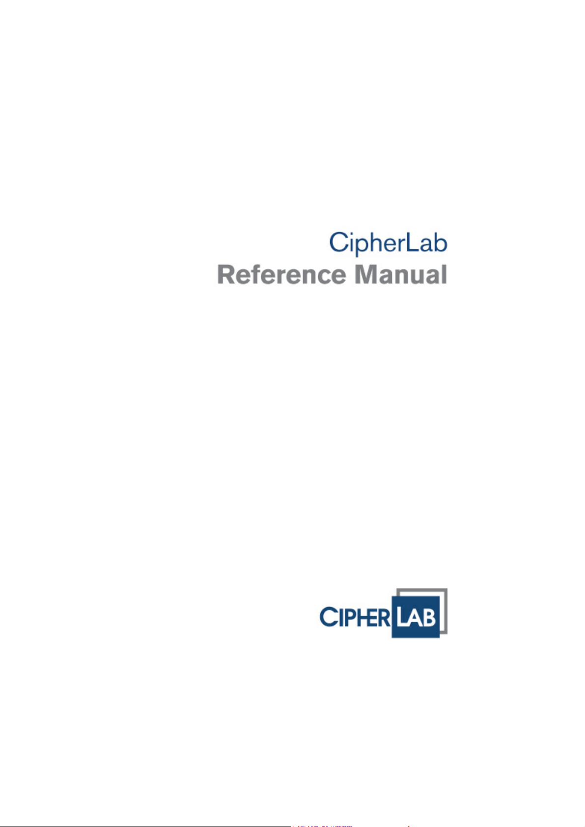
GETTING FAMILIARIZED WITH 8700
Figure 1: Overview
No. Description No. Description
1 Scanning window 2 Stylus
3 LCD touch screen 4 LED for Good Read, battery charging and
wireless data connections
5 Keypad, 24 or 44 keys 6 Battery Latch
7 Li-ion Battery, fit to compartment 8 Direct data-transmission/charging port
Warning: Always make sure the hand strap is well hooked and screwed to the back
of the mobile computer before use.
2
Page 13

Introduction
FEATURES
Ergonomic design — rugged yet streamlined, with hand strap for secure hold
Built tough to survive drop test and sealed against moisture/dust to IP 64
Dual mode support — one barcode scan engine plus the RFID reader
High capacity memory card (microSDHC) supported
Flexible wireless solutions — Bluetooth integrated, with connectivity options for
802.11b/g and 3.5G
FTP client support via 802.11b/g
Graphic monochrome LCD touch screen supports double-byte characters and bitmap
graphics
Programmable feedback includes buzzer, LED indicator, and vibrator
Quick link to any backend database through MIRROR Emulator programs for
VT100/220 and IBM 5250 emulation
Easy customization of data collection applications through FORGE Application
Generator (AG) programs for preloaded AG Runtime, batch and WLAN versions
available
Programming support includes BASIC & C compilers
Accessories include RS-232 cable, pistol grip, charging and communication cradle,
etc.
INSIDE THE PACKAGE
The following items are included in the package. Save the box and packaging material for
future use in case you need to store or ship the mobile computer.
8700 Series mobile computer
Rechargeable Li-ion battery pack
Hand strap
Stylus
Stylus tether
USB Cable
Utility CD
Quick Start Guide
5V Power Adapter
3
Page 14

8700 Series Mobile Computer Reference Manual
ACCESSORIES
Rich choices of optional accessories are made available for you to enhance the general
performance of the mobile computer.
Pistol Grip
Belt Holster
Protective Cover
Spare rechargeable Li-ion battery
Standard USB cable
RS-232 Cable
Universal power adapter
308 USB Virtual COM Interface Cable (convert RS-232 to USB)
Charging & Communication Cradle
4
Page 15

Introduction
GETTING STARTED
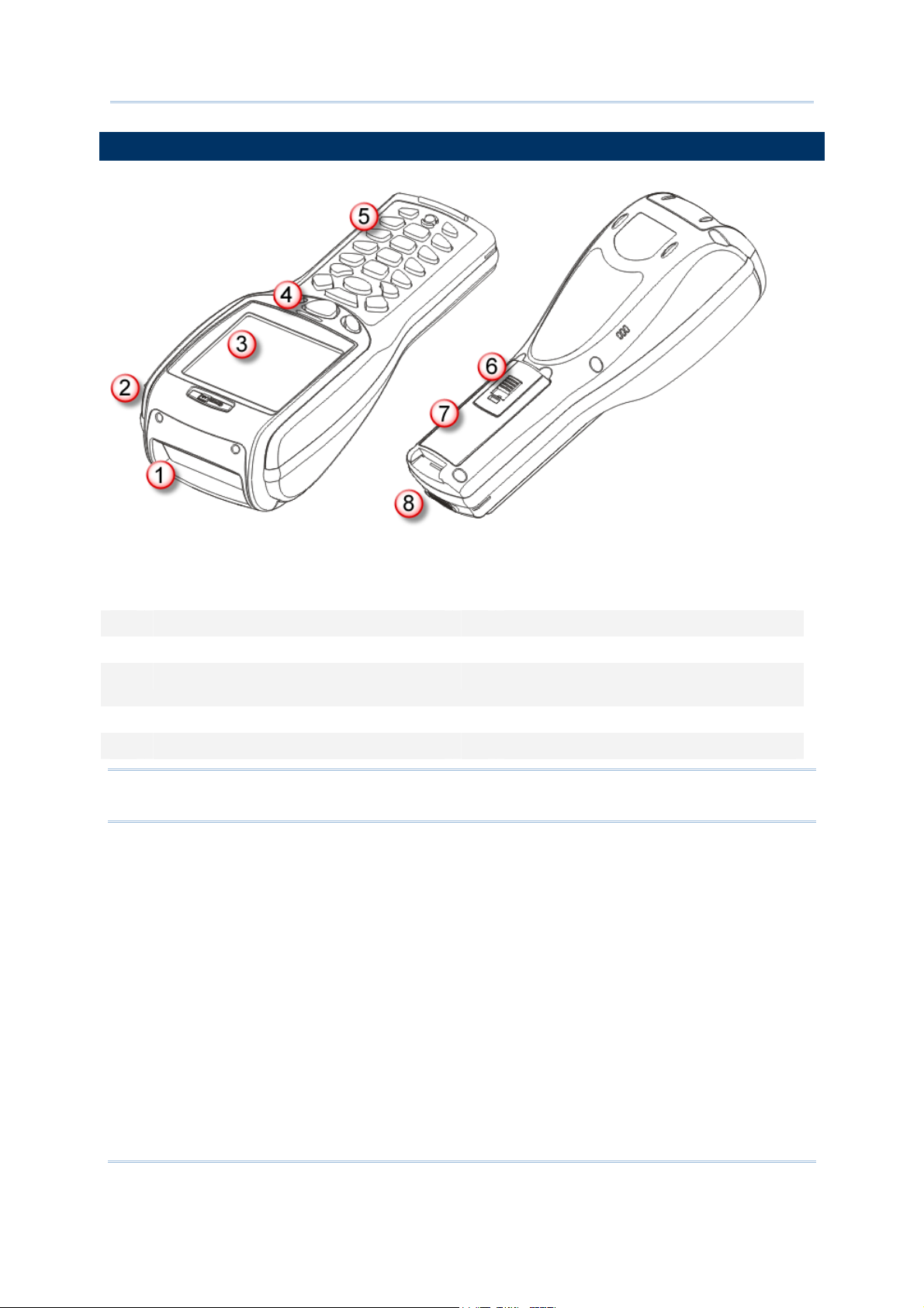
INSERTING BATTERY & MEMORY CARD
For shipping and storage purposes, save the mobile computer and the main battery in
separate packages. This will keep both batteries in good condition for future use.
Note: Any improper handling may reduce the battery life.
To set up the mobile computer to work:
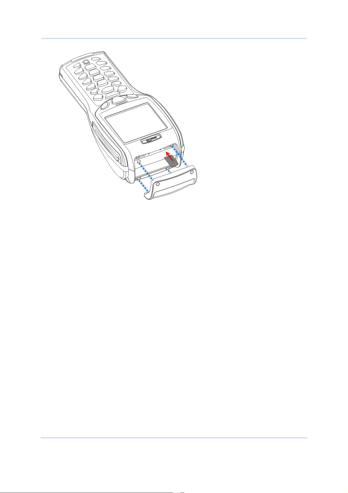
1) Hold the mobile computer still and release the hand strap from the bottom of the
mobile computer. Remove the battery pack to see the socket for an external SD card.
The socket has a hinged cover.
2) Slide-release the hinged cover.
3) Flip up the hinged cover.
4) Fit your memory card (microSD or microSDHC) into the socket.
5) Put down the hinged cover.
6) Slide-lock the hinged cover.
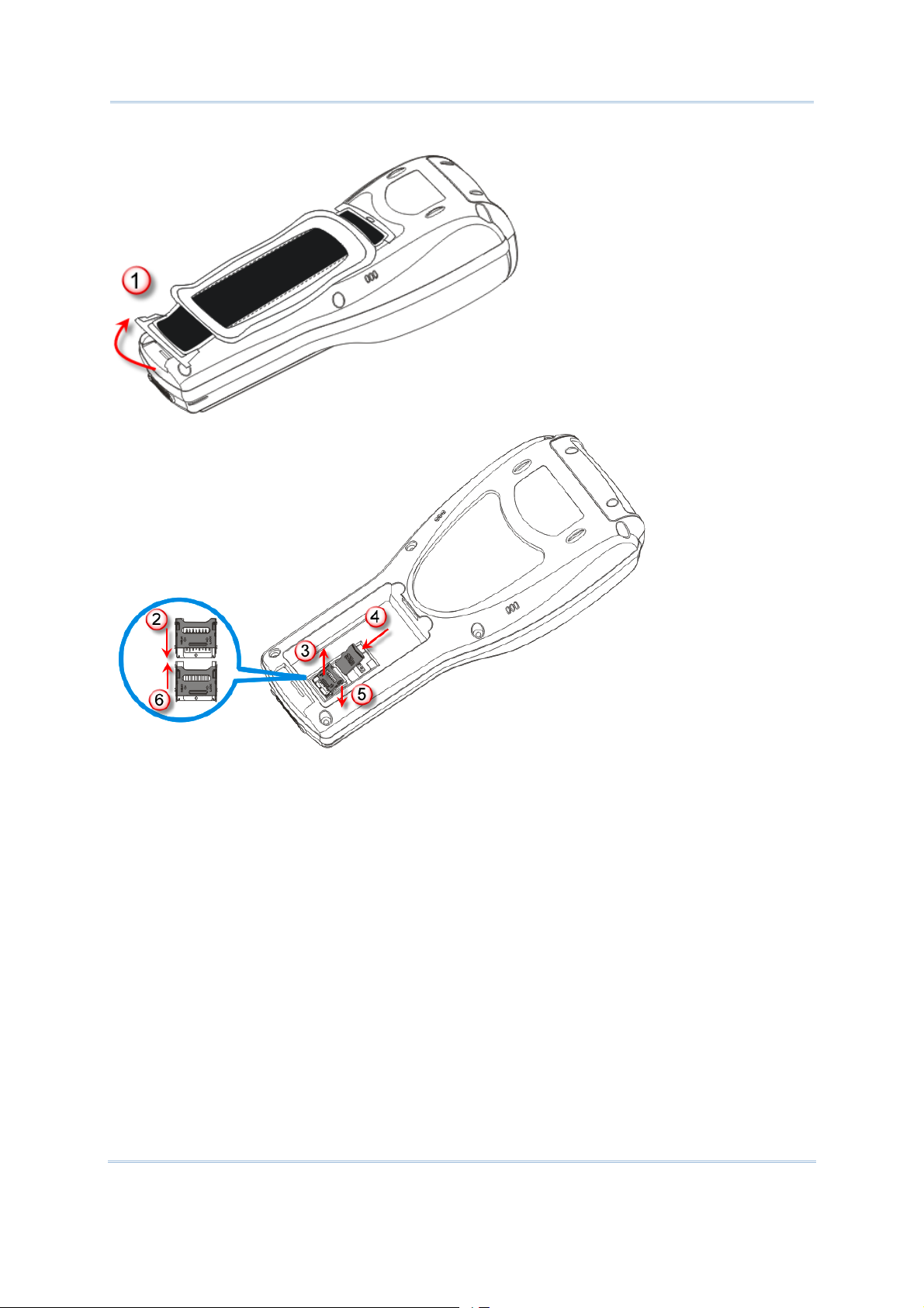
7) Reinstall the battery pack into the battery compartment at a proper angle (30°~45°)
that the metal contacts can meet. Make sure the battery is installed in place.
8) Slide the battery latch to the lock position.
9) Re-join the unfastened end of the hand strap to the mobile computer. Make sure the
hand strap is securely attached to the mobile computer before use.
10) The hand strap is ideal for one-hand operation and ensures safe and convenient hold
of the mobile computer.
Note: For a new battery, make sure it is fully charged before use. Always prepare a
spare battery pack, especially when you are on the road.
5
Page 16
8700 Series Mobile Computer Reference Manual
Unlock
Lock
6
Page 17
Introduction
Figure 2: Installing Memory Card & Battery
INSERTING SIM CARD
The 8790 mobile computer is capable of data communications over free air, right on the
road.
To insert a SIM card:
1) Turn off the mobile computer.
2) Remove the top shield by unfastening the four screws.
3) Find the SIM card slot inside the top of the mobile computer.
4) Insert the SIM card and make sure its gold contacts and notched corner are
positioned correctly as shown.
5) Restore the top shield by re-fastening the 4 screws.
7
Page 18
8700 Series Mobile Computer Reference Manual
Figure 3: Inserting SIM Card
8
Page 19

Introduction
INITIAL CHARGING
Due to shipment, it is likely the main battery and backup battery aren’t fully charged
when you receive the package. Before setting the mobile computer to work, charge the
main battery to full by direct charging using the power adapter (with the help of the USB
Charging & Communication Cable or Cradle). Refer to
Since the main battery is the only source that the backup battery taps power from, be
sure to install the main battery when you first charge the mobile computer so both main
battery and backup battery get charged.
Some key facts about charging the batteries:
1.7 Charging & Communications.
Battery charging stops when the temperature drops below 0°C or exceeds 40°C. It is
recommended the battery be charged at room temperature (18°C to 25°C) for the
optimal performance.
For initial charging, it takes approximately 5 hours for the power adapter to charge
the battery to full on condition that the mobile computer is turned off.
It takes at least 24 hours to fully charge the backup battery. However, it is not
necessary to fully charge the backup battery for the mobile computer to work.
Note: In order to charge the backup battery to full, you must insert the main battery and
leave it for at least 24 hours, whether the mobile computer is in use or not.
SETTING LOCAL TIME
If you need to set your local time, go to System Menu | 2. Settings | 1. Clock. Refer
3.2.1 Clock.
to
POWER MANAGEMENT
For any portable device, power management is a critical issue especially when you are on
the road. Some tips are listed below to help you save battery power.
Warning: Using backlight, wireless connectivity, and peripherals on battery power
will substantially reduce battery power.
To speed up charging the mobile computer, turn off the mobile computer and seat it
in the cradle or use the charging/communication cable.
Bring a second battery pack on the road.
Disable wireless connectivity, Bluetooth, 802.11b/g or 3.5G when it isn’t in use.
Go to System Menu | 2. Settings | 2. Backlight, and configure backlight duration
and brightness. Refer to
3.2.2 Backlight.
Go to System Menu | 2. Settings | 3. Auto Off, and configure the idle time (by
minute) before the system shuts down automatically. Refer to
3.2.3 Auto Off.
9
Page 20

8700 Series Mobile Computer Reference Manual
10
Page 21

Chapter 1
USING MOBILE COMPUTER
This chapter walks you through the features and the functions that 8700 mobile
computers deliver. The 8700 lineup includes the following variations:
8700 Bluetooth Class 2
8770 Bluetooth Class 2 + 802.11b/g
8790 Bluetooth Class 2 + 802.11b/g + 3.5G
IN THIS CHAPTER
1.1 Battery..................................................................... 11
1.2 Memory.................................................................... 13
1.3 Keypad..................................................................... 14
1.4 LCD ......................................................................... 22
1.5 Notifications.............................................................. 24
1.6 Data Capture ............................................................ 25
1.7 Charging & Communications........................................ 30
1.8 SD Card ................................................................... 36
1.1 BATTERY
1.1.1 MAIN BATTERY
The mobile computer is fed by a rechargeable 3.7 V/4000 mAh Li-ion battery pack. When
the mobile computer is turned off, it takes approx. 5 hours to charge it to full from the
power adapter (using RS-232 cable or cradle) or approx. 14 hours from the USB cable (at
500 mA).
For power-saving purpose, always turn off the backlight while working in a well-lit area.
When the backlight is on for extended periods of time, the main battery will become low
sooner than expected.
The smart battery icon on the LCD screen shows the status of power consumption. There
are two ways to monitor the battery charge:
Examine the level of the 4-bar battery icon on the screen
Check up the voltage level by System Menu (see 3.5 Power)
11
Page 22

8700 Series Mobile Computer Reference Manual
1.1.2 BACKUP BATTERY
The backup battery on the main board takes the responsibility to supply power to the
mobile computer when the main battery is removed or drained out. When fully charged,
the 3.0 V/7 mAh rechargeable Lithium button cell helps retain data in SRAM and maintain
the running of the real-time clock and calendar for at least 25 days without the main
battery. In the meantime, you have to replace the main battery as soon as possible. It
takes at least twenty-four hours to fully charge the backup battery. However, it is not
necessary to fully charge the backup battery for the mobile computer to work.
Monitor voltage level by System Menu (see 3.5 Power)
1.1.3 CAUTION OF LOW BATTERY CHARGE
The battery pack is the only power source for the mobile computer to work. It also
charges the backup battery on the main board so the data stored in SRAM can be
retained properly. Therefore when the main battery charge goes low, you need to replace
the battery pack with a charged one or charge it as soon as possible. Most of all, you
should upload important data on a regular basis.
Warning: Data loss may occur with SRAM during low battery condition. Always save
data before running out of power or keep a fresh battery for replacement.
12
Page 23

Chapter 1 Using mobile computer
1.2 MEMORY
The collected data can be sent back to a host computer immediately over wireless data
connections, or stored in memory (SRAM) for a later upload. The mobile computer is
equipped with a calendar chip for accurate time/date logging. When the main battery is
removed or drained, the backup battery on the main board takes over to retain the
contents of SRAM and keep the real-time clock and calendar running. When fully charged,
it keeps said jobs up for at least 25 days.
If you want to put away the mobile computer for a couple of days, you should be aware
that data loss occurs when both the main and backup batteries discharge completely.
Therefore it is necessary to upload data and files before putting away the mobile
computer!
1.2.1 READ-ONLY MEMORY (ROM)
8 megabytes flash memory for storing core, OS, application programs, fonts, etc.
1.2.2 RANDOM-ACCESS MEMORY (RAM)
Options include 4 or 16 megabytes SRAM for storing data. Its contents will be retained by
the backup battery.
1.2.3 SD CARD
Secure Digital (SD) card is a flash memory data storage device. High capacity memory
card (microSDHC) is supported. Refer to
insert the microSD or microSDHC card. For more details, refer to
Note: (1) When SD card is present, the card icon will appear on the screen and flash
while being accessed.
(2) For an SD card that has never been used on the mobile computer, a message
like “Found New SD Card” will be displayed allowing users to scan the card for
memory check. If you don’t feel the need for an instant check on the memory, you
can select cancellation and perform the memory check later through System
Menu. See
3.8 SD Card Menu.
Inserting Battery & Memory Card for how to
1.8 SD Card.
13
Page 24
8700 Series Mobile Computer Reference Manual
1.3 KEYPAD
For input device, the mobile computer keeps 2 keypad layouts optional, either a 24-key
type or a 44-key one. Both keypad gets programmable LED backlight as the screen does.
Refer to
1.4 LCD for screen & backlight settings.
Silicon rubber has been chosen for the keys due to durability and easy activation. The
key click sound is configurable through programming or via System Menu. Refer to
3.2.5 Key Click.
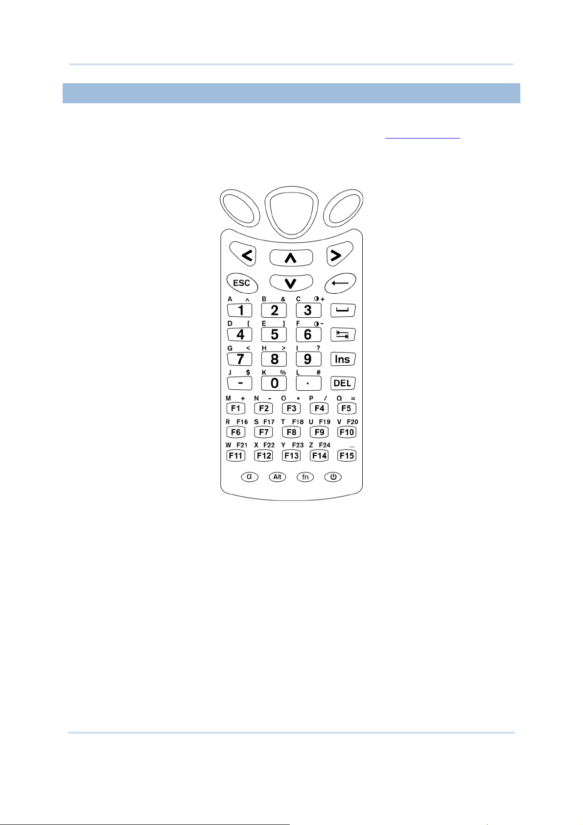
1.3.1 24-KEY LAYOUT
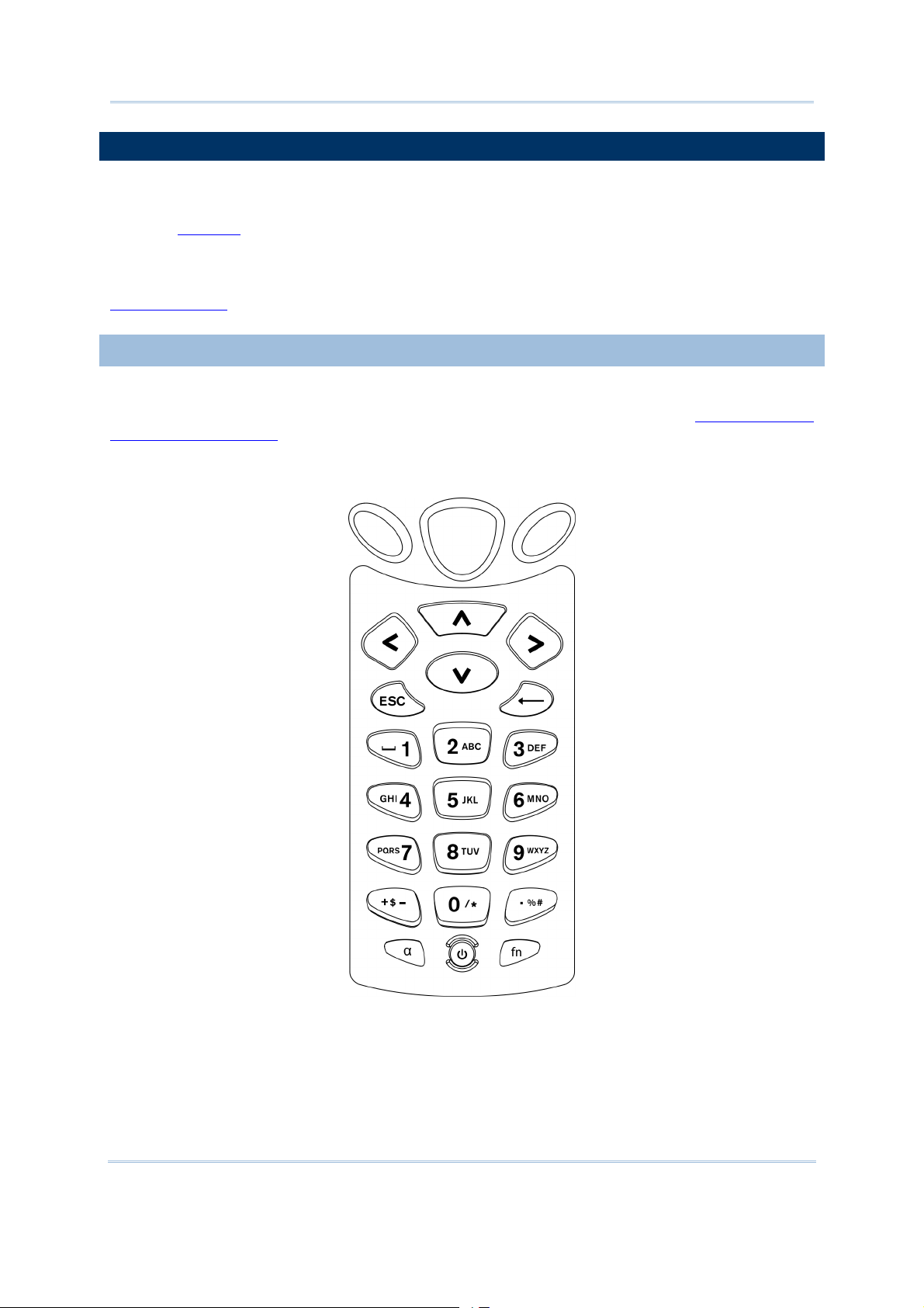
The layout of the 24-key keypad is similar to a telephone keypad. It wedges
alphanumeric, navigation, function keys, and a few symbol keys. Refer to Appendix III —
Key Reference Tables for all the characters it enters.
Figure 4: 24-key Layout
14
Page 25
Chapter 1 Using mobile computer
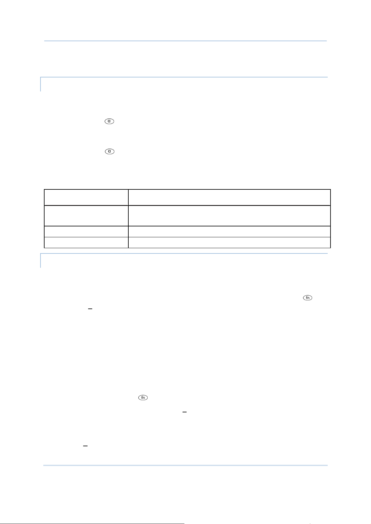
This 24-key alphanumeric keypad enters numbers by default. The keypad’s alphabet key
switches the keypad to alphabetic input. A few symbols are supported when the
keypad sits in alphabetic input, whether uppercase or lowercase.
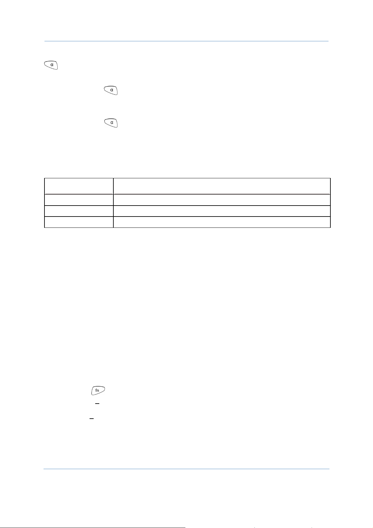
Press the [α] key (repeatedly) until the mobile computer shows an “A”, which we
might as well call “the alphabet icon”, at the lower-left of the screen. The keypad starts
to enter all caps and a few symbols without holding down the [α] key.
Press the [α] key
(repeatedly) until the mobile computer shows an “a”, which we
might as well call “the alphabet icon”, at the lower-left of the screen. The keypad starts
to enter all lowercase letters and a few symbols without holding down the [α] key.
Note the letter case doesn’t impact the symbols.
An overview of the alphabet icons and the keypad’s input mode:
Alphabet Icons
None Numbers, hyphen minus “-”, and dot “.”
A All uppercase letters and symbols
a All lowercase letters and symbols
Keypad’s Input Mode
When inputting alphabetic characters, the letters and the number printed on a key take
turn to show where the cursor is when you keep pressing that key; each press must not
exceed one second. For example, when you keep press the number key [2], the letters
“A”, “B”, “C” and the number “2” take turn to show for uppercase while “a”, “b”, “c” and
“2” will take turn to show for lowercase.
When you first press the number key [2], the letter “A” or “a” is produced.
When you press the number key [2] twice (the time interval must not exceed one
second), the letter “B” or “b” is produced.
When you press the number key [2] three times (the time interval between each
press must not exceed one second), the letter “C” or “c” is produced.
When you press the number key [2] four times (the time interval between each press
must not exceed one second), the number “2” is produced.
In order to get the desired character, you need to press the same key one to four times
(the time interval between each press must not exceed one second). Only when the
pressing stops for longer than one second or another key is pressed will the system send
out the due key code or change over to send another key code to the active application
program.
The [fn] key
associated icon F
is pressed with a number key. Upon your pressing [fn] key, its
displays at the bottom-left of the screen of the mobile computer. Press
the second key, say [5], to complete the key combination and produce [F5] function.
Then the icon F
goes off automatically.
15
Page 26
8700 Series Mobile Computer Reference Manual
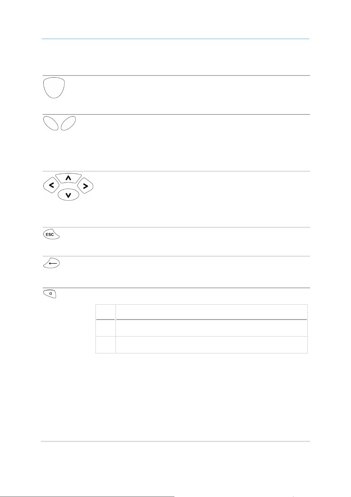
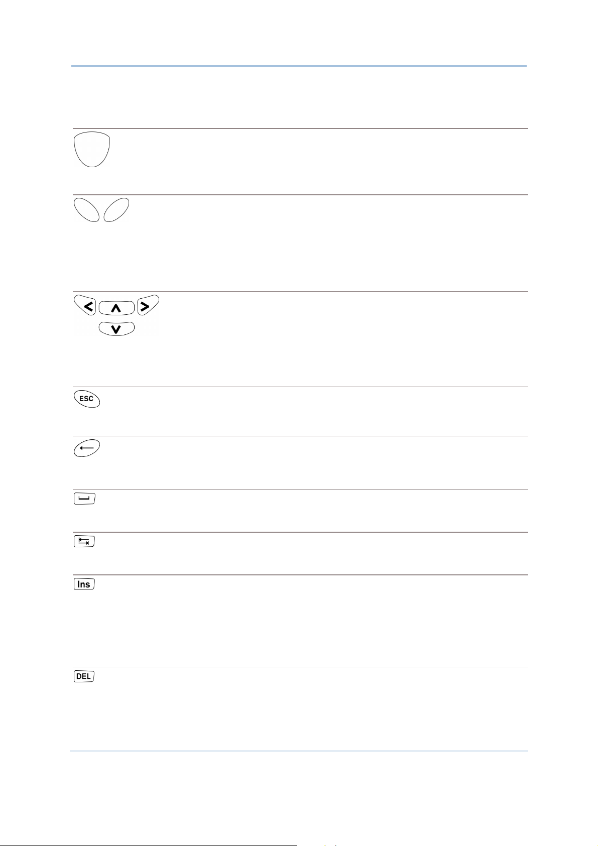
Functions of the common keys are briefly described as below:
SCAN
Triggers the scan engine so it reads a barcode when reader function is enabled.
ENTER
The two [Enter] keys on both sides of the [SCAN] key are user-friendly and
convenient for both right-handed and left-handed operators.
Both keys execute commands or confirm input.
Press the [fn] key the press either of these [Enter] keys to turn on/off
backlight for the LCD and keypad.
Navigation Keys
These keys move the cursor left, up, down, or right.
Press the [fn] key then press either of up/down key to decrease/increase
LCD contrast.
Press the [fn] key then press either of left/right key to decrease/increase
the LCD backlight brightness.
the
ESC (Escape)
← (Backspace)
α (Alphabet Key)
Stops and quits the current operation.
Deletes the preceding character where the cursor is. If this key is pressed and
held, a clear code is sent.
This key is a modifier key that requires a second key pressed to get the
yellow-engraved letters (A~Z) and symbols.
Icon Description
A This icon appears at the lower-left of the screen to indicate keypad
set to enters all uppercase letters and symbols.
a This icon appears at the lower-left of the screen to indicate the
keypad set to enters all lowercase letters and symbols.
16
Page 27

Chapter 1 Using mobile computer
fn (Function Key)
This key is a modifier key that requires a second key ([0] ~ [9]) pressed to
deliver the value of key combination.
Icon Description
F In default state, the function toggle is set to “Auto Resume” and
operates as described below:
This icon appears when you press the function key [fn], indicating
the keypad set to the function key input. Press a second key to
get the desired function.
POWER Key
In order to prevent an accidental press of the POWER key, you need to press
and hold this key for approximately 1.5 seconds to turn on/off the mobile
computer.
Note: (1) Functionality of keys is application-dependent. The system will send the
associated key code to the application program, and it is up to the application
program to interpret the key code.
(2) As long as a status icon appears on the screen, it indicates a certain mode has
been activated and it isn’t necessary to hold the modifier key.
Once the second key is pressed, the icon goes off automatically.
17
Page 28
8700 Series Mobile Computer Reference Manual
1.3.2 44-KEY LAYOUT
The 44-key keypad wedges numeric, alphabetic, navigation, function keys and the
modifier keys. Refer to Appendix III — Key Reference Tables:
characters it enters.
44-key Keypad for all the
Figure 5: 44 key Layout
18
Page 29
Chapter 1 Using mobile computer
In default state, this 44-key alphanumeric keypad enters numbers and launches the
functions of F1 through F15.
THE [ALPHA] KEY
Press the blue modifier key [α] to toggle the keypad among numeric, uppercase
alphabetic, and lowercase alphabetic modes.
Press the [α] key
(repeatedly) until the mobile computer shows an “A”, which we
might as well call the “alphabet icon”, at the lower-left of the screen. The keypad starts
to enter all uppercase letters without the need to hold down the [α] key.
Press the [α] key
(repeatedly) until the mobile computer shows an “a”, which we
might as well call the “alphabet icon”, at the lower-left of the screen. The keypad starts
to enter all lowercase letters without the need to hold down the [α] key.
An overview of the alphabet icons and the keypad’s input modes:
Alphabet Icons
None Enters numbers, hyphen minus “-”, and dot “.”
Keypad’s Input Mode
Launches F1 through F15.
A All uppercase letters
a All lowercase letters
THE [FN] KEY
The orange [fn] key makes the keypad enter the orange-engraved characters. After the
[fn] key is pressed, it requires you to press a second key to complete the action.
Here are the basics how this [fn] key works: You first press the orange [fn] key
see an icon F
shows at the lower-left of the screen. Then you press another key
engraved with an orange-colored character/graphic to produce the following:
and
1) Entering that orange-colored character (mostly symbols).
2) Launching the functions of F16 through F24.
3) Increasing/decreasing backlight brightness for the screen and the keypad.
The [fn] key is set to “Auto Resume” by default, which means the [fn] key is enabled
once pressed, and becomes disabled once the second key is pressed.
Here’s an example how you produce the function of [F16]:
1) Press the orange [fn] key
The mobile computer’s screen shows an F
.
at the lower-left of the screen.
2) Press the key [F6], which is engraved with the orange-colored “F16”.
The system produces the function of [F16].
The icon F
goes off.
19
Page 30
8700 Series Mobile Computer Reference Manual
Functions of the common keys are briefly described as below.
SCAN
Triggers the scan engine so it reads a barcode when the reader function is
enabled.
ENTER
The two [Enter] keys on both sides of the [SCAN] key are user-friendly and
convenient for both right-handed and left-handed operators.
Both of them execute commands or confirm input.
Press the [fn] key then press either of these [Enter] keys to turn on/off
backlight of LCD and keypad.
Navigation Keys
These keys move the cursor left, up, down, or right.
Press the [fn] key then press either of up/down key to decrease/increase
LCD contrast.
Press the [fn] key then press either of left/right key to decrease/increase
the LCD backlight brightness.
the
ESC (Escape)
← (Backspace)
9
(Space)
) (Tab)
Ins (Insert)
DEL (Delete)
Stops and quits the current operation.
Deletes the preceding character where the cursor is. If this key is pressed and
held, a clear code is sent.
Inserts a blank space at the position where the cursor is.
Moves the cursor to the next tab stop.
Switches the keypad between the overtype mode and insert mode. This key
helpful when the mobile computer is working on terminal emulation.
In overtype mode, when you are typing, the cursor overwrites any character
that is right after its current position. In insert mode, when you are typing, the
cursor inserts a character at its current position.
Deletes the character at the back of the cursor.
is
20
Page 31

Chapter 1 Using mobile computer
α (Alphabet Key)
Alt Key
This key is a modifier key that requires a second key pressed to produce
blue-engraved letters (A~Z).
Icon Description
A This icon appears at the lower-left of the screen to indicate keypad
set to enter all uppercase letters.
a This icon appears at the lower-left of the screen to indicate keypad
This key is a modifier key that alters the next key pressed. The functionality
depends on the application that is active at the moment.
set to enter all lowercase letters.
Icon Description
A This icon appears when you press [Alt] to enter the special function
mode.
the
fn (Function Key)
This key is a modifier key that requires a second key pressed to enter the
orange-engraved characters (mostly symbols) and produce the function of F16
through F24.
Icon Description
F The function toggle is set to “Auto Resume” by default which operates
as described below:
This icon appears when you press the orange modifier key [fn],
indicating the keypad set to function key input. Then you press a
second key to enter the desired symbols or produce the desired
function.
Once the second key is pressed, the icon F goes
Power Key
In order to prevent an accidental press of the POWER key, you need to press
and hold down this key for approximately 1.5 seconds to turn on/off the mobile
computer.
Note: (1) Functionality of keys is application-dependent. The system will send the
associated key code to the application program, and it is up to the application
program to interpret the key code.
(2) When a status icon appears on the lower-left of the screen, it indicates a
certain mode is activated and it is not necessary to hold down the modifier key.
automatically.
off
21
Page 32

8700 Series Mobile Computer Reference Manual
1.4 LCD
The mobile computer ships with a 3” FSTN graphic LCD, 160 by 160 pixels resolutions,
which can be programmed to display text or graphics such as specific font and company
logo to meet various applications.
Options
English font Font size 6×8 (pixels)
Chinese font Font size 12×12 (pixels)
Other language fonts, company logo… Programmable
Font Size (pixels) Characters by lines
26 characters by 19 lines
Font size 8×16 (pixels)
Font size 16×16 (pixels)
20 characters by 9 lines
13 characters by 12 lines
10 characters by 9 lines
Note: The bottom line (ICON_ZONE) is reserved to display status icons, such as the
battery icon.
1.4.1 ADJUSTING THE BACKLIGHT
The backlight of screen and keypad makes it easier to operate the mobile computer in
dim environments. By pressing the following key combinations, LCD backlight can be
turned on/off and the brightness can be adjusted. Keep pressing the key combination
until the brightness or contrast decreases or increases to a desired level. Alternatively
the brightness and contrast are controllable through programming or via System Menu.
Refer to
Note: Using backlight on battery power will substantially reduce battery power. We
3.2.2 Backlight and 3.2.13 Contrast.
suggest that you dim the backlight while working in a well-lit area or set it to
automatic power off when the computer isn’t actively used.
Use the following key combinations to adjust the backlight for the mobile computer’s LCD
and keypad, and also the contrast for the LCD. Combine the keys by pressing the [fn]
key first and then pressing the second key.
Key Combination
24-key 44 key
+ [Enter]
+ [Up]
+ [Down]
+ [Right]
+ [Left]
+ [3] Same as + [Up]
+ [Enter] Toggles on/off the backlight
+ [Up] Increases the contrast of LCD
+ [Down] Decreases the contrast of LCD
+ [Right] Turns on the backlight and increases the brightness of
+ [Left] Turns on the backlight and decrease the brightness of
Action
LCD/keypad backlight.
LCD/keypad backlight.
22
Page 33

Chapter 1 Using mobile computer
+ [6] Same as + [Down]
1.4.2 CALIBRATING THE SCREEN
This LCD is a touch screen that supports touch control by a stylus. It also features
signature capture so signatures can be saved to serve as receipt confirmation when
goods are delivered to door.
Refer to
3.2.8 Screen Calibration for screen calibration.
Warning: DO NOT contact the screen surface with any pointed or sharp object.
23
Page 34

8700 Series Mobile Computer Reference Manual
1.5 NOTIFICATIONS
1.5.1 STATUS LED
A LED indicator is recessed above the [SCAN] button. It presents dual modes and each
mode presents dual colors. This LED indicator can be programmed to provide information
that helps diagnosing the status of the mobile computer. For example, if you are using
AG Runtime, you will be informed of the scanning result immediately. LED1 is used for
"Good Read" and will become solid green upon reading a barcode successfully.
LED1 provides the information on the charging status and barcode reading.
LED2 provides the information on wireless communications.
LED1: Red/Green
User Power ON User definable User definable
Red Green
Solid green for Good Read by
default
Power Off, Battery
Charging
Charging Error System default
System default
Flashing red: Charging
System default
Flashing green: Charging done
Flashing red and green: Charging error occurs
LED2: Blue/Green Blue Green
Bluetooth System default
---
Flashing blue, quickly: Waiting for
connection or connecting
Flashing blue, slowly: Connected
Wi-Fi --- System default
Flashing green, quickly: Waiting
for connection or connecting
Flashing green, slowly:
Connected
1.5.2 AUDIO
The mobile computer has a low power transducer type buzzer that is programmable for
status feedback. In particular, its frequency and duration can be programmed for the
alert of Good Read in the provided terminal emulation programs.
1.5.3 VIBRATOR
The mobile computer is integrated with a vibrator that is programmable for status
feedback. It makes the mobile computer applicable to work in noisy environments. In
particular, the vibrator can be programmed for the alert of Good Read in the provided
terminal emulation programs.
24
Page 35

Chapter 1 Using mobile computer
1.6 DATA CAPTURE
Options of different reader combination are supported including 1D+RFID and 2D+RFID.
For each combination, both readers can be initialized and ready for scanning at the same
time (dual mode operation). For example, if you press the [SCAN] trigger while running
the preloaded AG runtime on the mobile computer, it will read a barcode in position or an
RFID tag in proximity depending on which one comes first.
Note: You cannot have 1D+2D scan engines installed on the mobile computer because
they are both barcode readers.
Varying by the reader type installed, the supported symbologies or tag types are listed
below:
1D CCD scan engine
1D Laser scan engine
1D Long Range Laser scan engine (LR)
2D scan engine
RFID reader
1.6.1 SYMBOLOGIES SUPPORTED
A wide variety of scan engines is available for delivering flexibility to meet different
requirements. Depending on the scan engine integrated, the mobile computer is capable
of scanning barcodes of a number of symbologies that are enabled by default while
running the preloaded AG runtime. Refer to
If you need to scan barcodes that are encoded in a symbology that is disabled by default
in AG runtime, FORGE Application Generator (ForgeAG.exe) can help you configure
symbology settings and reader settings. First, enable the desired symbologies in FORGE
Application Generator, and then download the application settings to the mobile
computer.
Note: In AG or CipherNet runtime, not all of the symbologies are enabled by default.
Instead of running any of them, you can develop your own applications to control
the scan engine for data collection. For details on configuring reader and
symbology settings, please refer to the documentation of the software you use.
Symbologies Supported (Default Setting: Enable/Disable) CCD/Laser LR 2D
Codabar Enabled Enabled Enabled
Code 11 Disabled Disabled
3.3.1 Reader for functional test.
Code 93 Enabled Enabled Enabled
Composite
Code
25
CC-A/B Disabled
CC-C Disabled
TCIF Linked Code 39 Enabled
Page 36

8700 Series Mobile Computer Reference Manual
MSI Disabled Disabled Disabled
Plessey Disabled
Postal Codes Enabled
Telepen Disabled
Code 128
Code 2 of 5
Code 3 of 9
EAN/UPC
Code 128 Enabled Enabled Enabled
GS1-128 (EAN-128) Enabled Enabled Enabled
ISBT 128 Enabled Enabled Enabled
Industrial 25 (Discrete 25) Enabled Enabled Enabled
Interleaved 25 Enabled Enabled Enabled
Matrix 25 Disabled Disabled
Chinese 25 Disabled
Coop 25 Disabled
Code 39 Enabled Enabled Enabled
Trioptic Code 39 Disabled Disabled
Italian Pharmacode (Code 32) Disabled Disabled Disabled
French Pharmacode Disabled
EAN-8 Enabled Enabled Enabled
EAN-8 Addon 2 Disabled Disabled Disabled
EAN-8 Addon 5 Disabled Disabled Disabled
EAN-13 Enabled Enabled Enabled
EAN-13 & UPC-A Addon 2 Disabled Disabled Disabled
GS1 DataBar
(RSS)
EAN-13 & UPC-A Addon 5 Disabled Disabled Disabled
Bookland EAN (ISBN) Disabled Disabled Disabled
UPC-E0 Enabled Enabled Enabled
UPC-E1 Disabled Disabled Disabled
UPC-E Addon 2 Disabled Disabled Disabled
UPC-E Addon 5 Disabled Disabled Disabled
UPC-A Enabled Enabled Enabled
GS1 DataBar Omnidirectional
(RSS-14)
GS1 DataBar Truncated Disabled Enabled Enabled
GS1 DataBar Stacked Disabled Enabled Enabled
GS1 DataBar Stacked Omnidirectional Disabled Enabled Enabled
GS1 DataBar Limited (RSS Limited) Disabled Enabled Enabled
GS1 DataBar Expanded (RSS
Expanded)
GS1 DataBar Expanded Stacked Disabled Enabled Enabled
Disabled Enabled Enabled
Disabled Enabled Enabled
26
Page 37

Chapter 1 Using mobile computer
2D
Symbologies
PDF417 Enabled
MicroPDF417 Enabled
Data Matrix Enabled
Maxicode Enabled
QR Code Enabled
27
Page 38

8700 Series Mobile Computer Reference Manual
1.6.2 RFID TAGS SUPPORTED
The RFID reader supports read/write operations depending on the tags. The supported
labels include ISO 15693, Icode®, ISO 14443A, and ISO 14443B. Currently, the
performance of some tags has been confirmed, and the results are listed below for your
reference. Refer to
Note: You should study the specifications of RFID tags before use.
HF Tag Protocol UID Read/Write
ISO 14443A
ISO 14443B
ISO 15693
3.3.9 RFID for functional test.
Mifare Standard 1K (Mifare S50)
Mifare Standard 4K (Mifare S70)
Jcop41 (Mifare 1K & 4K compatible)
Mifare Ultralight
Mifare Ultralight C
Mifare ProX
Mifare DESFire
Mifare Plus
Mifare Mini (Mifare S20)
SLE66CLX320P
SLE55R04 / 08
Smart MX
Jewel
Topaz
SLE6666CL160S
SR176
SRIX4K
SLIX4K
ISO 14443A Compliant
ISO 14443B Compliant
EM4135
ICODE SLI
LRI12
LRI64
LRI128
LRI2K
SRF55V**P
SRF55V**S
9 9
9 9
9 9
9 9
9 9
9 9
9 9
9 9
9 9
9
9
9
9 9
9 9
9
9 9
9 9
9 9
9
9
9 9
9 9
9 9
9 9
9 9
9 9
9 9
9 9
--
--
--
--
-- Dual
--
28
Page 39

Chapter 1 Using mobile computer
Tag-it HF-I Std
TempSense
ICODE1 with EAS&AFI
ICODE
9 9
9
--
9 9
9 9
29
Page 40

8700 Series Mobile Computer Reference Manual
1.7 CHARGING & COMMUNICATIONS
Normally the mobile computer ships with a USB cable for charging and communications.
A variety of cradles are also developed and made available to you to meet your needs.
USB Interface Cable
Task USB Cable
Charging USB direct charging
500 mA: USB icon
0 mA: Disable charging for 8700
5 V charging from the adapter (Plug icon)
Communications USB Virtual COM — If you have FORGE Application Generator installed on
your PC, you may use a download utility to receive data from your PC; or
you can run HyperTerminal.exe to receive data directly.
USB HID — Run a text editor on your PC to receive data directly.
USB Virtual COM_CDC —If you have FORGE Application Generator installed
on your PC, you may use a download utility to receive data from your PC;
or you can run HyperTerminal.exe to receive data directly.
Note: (1) If you are using USB Virtual COM for the first time, you must install its driver
from the CD-ROM. Driver version 5.3 or later is required. Please remove older
versions! The virtual COM port will not be assigned until the USB port is in use.
(2) If you are using USB Virtual COM_CDC for the first time, you must install its
driver from the CD-ROM. USB CDC driver installer can be found in the “Windows”
folder. It will proceed to install the driver to your PC.
(3) A standard USB cable releases a COM port in the following conditions: (i) the
cable is detached from the mobile computer directly, (ii) the cable is detached
from the cradle directly, (iii) the cable is attached to the cradle, but the mobile
computer is removed from the cradle, (iv) the mobile computer is powered off, (v)
no application that requires a virtual COM port is running on the mobile computer.
(4) For an application program that requires a COM port to be occupied all the
time, it is suggested that you use a 308 USB Virtual COM Interface cable instead.
30
Page 41

Chapter 1 Using mobile computer
RS-232 Interface Cable
Task RS-232 Cable + 5V Power Adapter
Charging 5 V charging from the adapter (Plug icon)
Communications If you have FORGE Application Generator installed on your PC, you may
use a download utility to receive data from your PC; or you can run
Cradle
Task Cradle Interface + 5V Power Adapter
Charging 5 V charging from the adapter (Plug icon)
HyperTerminal.exe to receive data directly.
Communications Depends on the cradle type and its associated settings —
USB
RS-232
Note: Battery charging stops when the temperature drops below 0°C or exceeds 40°C.
It is recommended that the battery be charged at room temperature (18°C to
25°C) for optimal performance.
31
Page 42

8700 Series Mobile Computer Reference Manual
1.7.1 INTERFACE CABLE OPTIONS
When charging by the USB cable, the standard charging current is 500 mA. However, it is
recommended that you charge the mobile computer by the external power source
through the power adapter to speed up charging the battery.
If you want to disable charging for 8700, change the charging current to 0 mA after
connecting the USB cable. Refer to
3.2.10 USB Charge Current.
Push & release
Universal Power Adapter
Figure 6: Using USB/RS-232 cable
Warning: It is not allowed for the mobile computer to run solely by USB power
without a battery loaded. It will display a warning message “Battery
Missing” along with an audible alert. In this case, you should install the
battery before restarting.
1.7.2 CHARGING & COMMUNICATION CRADLE
The cradle supports charging and data connection at the same time.
1) Seat the mobile computer in the cradle.
2) Connect the power supply cord to the power receptacle on the cradle.
3) Connect the adapter’s wall-wart plug to a power outlet.
32
Page 43

Chapter 1 Using mobile computer
4) Connect the charging & communication cable if data connection is required.
Note: (1) Tighten the two screw-in connectors to secure the cable.
(2) As the mobile computer will be charged via cradle, the power receptacle on the
charging & communication cable is inefficacious.
Figure 7: Setting up cradle
33
Page 44

8700 Series Mobile Computer Reference Manual
Charging & Communication Cradle
No. Description No. Description
1 LED Indicators (from left to right):
2 Charging Slot for the mobile computer
Charge
USB
TX/RX
Power
Refer to
Indicators
3 Charging Slot for Spare Battery 4 Cable Connector (USB or RS-232)
5 Power Jack
1.7.3 Understanding the LED
.
34
Page 45

Chapter 1 Using mobile computer
1.7.3 UNDERSTANDING THE LED INDICATORS
The LED indicators on the cradle deliver the cradle’s status. For the charging status of the
mobile computer’s main battery pack, check out the device’ screen.
Figure 8: Cradle LEDs
Indicator
Charge
Status Description
Off Charging failed
Red, solid Charging spare battery
Green, solid Charging done
Off No USB connection USB
Green, solid USB plug-in
Off No activity TX/RX
Green, flashing Transmitting data via RS-232
Off No power POWER
Red, solid Power ON
Warning: Charging error may occur due to a power failure or defected battery
contacts.
35
Page 46

8700 Series Mobile Computer Reference Manual
1.8 SD CARD
A SD card inserted in the mobile computer is directly accessible for user’s applications.
Yet when the mobile computer connects to the host computer via a USB cable, the SD
card can work as a removable disk (USB mass storage device) as long as it is configured
properly through programming or via System Menu | 8. Next Page | 1. SD Card
Menu | 1. Run As USB Disk. Refer to
Note: While running BASIC application, the size of DAT files on SD card can be calibrated.
Go to System Menu | 8. Next Page | 1. SD Card Menu | 2. Access SD Card | 4.
Check File Size to refresh the size of “A:\BASICRUN\TXACTn.DAT” (n=1~6).
3.8 SD Card Menu.
1.8.1 FILE SYSTEM
For 8700 Series, SD cards of FAT12/FAT16/FAT32 file systems are supported and card
formatting through C programming or via System Menu | 8. Next Page | 1. SD Card
Menu | 2. Access SD Card is supported. Based on the capacity of the card, it will
automatically decide the FAT format:
Card Capacity
> 8 GB
≦ 32 MB
≦ 1 GB
≦ 2 GB
≦ 8 GB
FAT Format Sectors per Cluster
FAT32 16
FAT12 32
FAT16 32
FAT16 64
FAT32 8
1.8.2 DIRECTORY
Unlike the file system on SRAM, the file system on SD card supports hierarchical tree
directory structure and allows creating sub-directories. Several directories are reserved
for particular use.
Reserved Directory
\Program
Related Application or Function Remark
System Menu | Load Program
Program Manager | Download
Program Manager | Activate
Kernel Menu | Kernel Update
This directory stores the programs that are
downloadable to the mobile computer:
C program — *.SHX
BASIC program — *.INI and *.SYN
UPDATE_BASIC()
\BasicRun BASIC Runtime This directory stores the DAT and DBF files
that are created and accessed in BASIC
runtime.
They are assigned the permanent filenames
as follows:
36
Page 47

Chapter 1 Using mobile computer
DAT Filename
DAT file #1 TXACT1.DAT
DAT file #2 TXACT2.DAT
DAT file #3 TXACT3.DAT
DAT file #4 TXACT4.DAT
DAT file #5 TXACT5.DAT
DAT file #6 TXACT6.DAT
DBF Filename
DBF file #1
DBF file #2
Record file F1.DB0
System Default
Index
Index file #1 F1.DB2
Index file #2 F1.DB3
Index file #3 F1.DB4
Record file F2.DB0
System Default
Index
Index file #1 F2.DB2
F1.DB1
F2.DB1
DBF file #3
DBF file #4
DBF file #5
Index file #2 F2.DB3
Index file #3 F2.DB4
Record file F3.DB0
System Default
Index
Index file #1 F3.DB2
Index file #2 F3.DB3
Index file #3 F3.DB4
Record file F4.DB0
System Default
Index
Index file #1 F4.DB2
Index file #2 F4.DB3
Index file #3 F4.DB4
Record file F5.DB0
System Default
Index
Index file #1 F5.DB2
F3.DB1
F4.DB1
F5.DB1
Index file #2 F5.DB3
Index file #3 F5.DB4
37
Page 48

8700 Series Mobile Computer Reference Manual
\AG\DBF
\AG\DAT
\AG\EXPORT
\AG\IMPORT
Application Generator (a.k.a. AG) This directory stores the DAT, DBF, and
Lookup files that are created and/or
accessed in Application Generator.
1.8.3 FILE NAME
A file name must follow 8.3 format (= short filenames) — at most 8 characters for
filename, and at most three characters for filename extension. The following characters
are unacceptable: “ * + , : ; < = > ? | [ ]
On 8700 Series, it can only display a filename of 1 ~ 8 characters (the null character
not included), and filename extension will be displayed if provided. If a file name
specified is longer than eight characters, it will be truncated to eight characters.
Long filenames, at most 255 characters, are allowed when using the mobile computer
equipped with SD card as a mass storage device. For example, you may have a
filename “123456789.txt” created from your PC. However, when the same file is
directly accessed on the mobile computer, the filename will be truncated to
“123456~1.txt”.
If a file name is not specified in ASCII characters, in order for the mobile computer to
display it correctly, you may need to download a matching font file to the mobile
computer first.
The file name is not case-sensitive.
38
Page 49

Chapter 2
LEARNING SOFTWARE ARCHITECTURE
This chapter describes the software preinstalled on the mobile computer — the Kernel,
System, and Application, and each has its own function menu.
When a menu displays, select an item by either of the following ways:
Press the navigation keys [Up] and [Down] to move between the menu items and
press [Enter] to select one.
Press the number key that corresponds to the menu item to select it.
Use a stylus to tap an item from the menu to select it.
Follow the on-screen instructions to change a setting, or press [ESC] to return to a
previous page or menu.
39
Page 50

8700 Series Mobile Computer Reference Manual
On each screen, the bottom line displays status icons, such as:
The 4-bar battery icon indicates the current power status.
The status icon of input mode is controlled by the modifier key: or
The status icon of function mode is controlled by the modifier key: or
The turn-page icon ( ) indicates there is a previous page or menu.
To return to a previous page or menu, you may press [ESC], touch the menu title, or
follow the on-screen instructions.
Figure 9: Software Architecture
IN THIS CHAPTER
2.1 Application Module..................................................... 41
2.2 System Configuration & Core....................................... 43
40
Page 51

Chapter 2 Learning Software Architecture
2.1 APPLICATION MODULE
The mobile computer ships with the software package on the CD-ROM. It includes
FORGE Application Generator (batch- and WLAN-versions), MIRROR Emulator (VT
and 5250 versions), download utilities, etc.
2.1.1 FORGE APPLICATION GENERATOR (AG)
For the easy development of applications, the mobile computer is preloaded with AG
runtime. When you turn on the mobile computer, it displays user application’s main
menu as below.
Batch AG
WLAN AG
Note: Batch AG supports automatically uploading data to a host computer when the
upload interface is properly configured. Once the mobile computer connects to the
host via a RS-232 or USB Virtual COM cable, a moving hourglass icon displays on
the upper-right corner of the screen to indicate the mobile computer ready for
auto upload.
Before you proceed to collect data with the mobile computer, configure the application
with the companion tool on your PC. This time-saving development tool helps create
mobile computer’s application templates on your PC.
For details on the AG application, refer to related user manual.
Application Generator
Batch AG U8700.SHX ForgeAG.exe
WLAN AG WU8700.SHX AG8700WLAN.exe
AG Runtime on mobile computer Companion Tool on PC
Note: FORGE Application Generator (AG) software package includes
(1) a companion tool for quickly developing your application — Batch or WLAN AG;
(2) several download utilities to make it versatile in use.
41
Page 52

8700 Series Mobile Computer Reference Manual
2.1.2 MIRROR EMULATOR (CIPHERNET)
The mobile computer supports VT100/220 and IBM 5250 terminal emulation for
accessing a backend database. Instead of using FORGE Application Generator, you
may download the terminal emulation program, i.e. CipherNet Runtime, to the mobile
computer. Refer to
3.6 Load Program. Then run individual companion tool on your
computer.
For details on the MIRROR Emulator application, refer to associated user manuals.
Terminal Emulation CipherNet Runtime on mobile computer Companion Tool on PC
VT100/220 87xx-VT.SHX CipherNet-VT.exe
IBM 5250 87xx-5250.SHX CipherNet-5250.exe
2.1.3 USER PROGRAM
You may need to develop your own application program. For developing custom
applications, CipherLab provides BASIC and C compilers through licensing. For detailed
information, contact your sales representative.
42
Page 53

Chapter 2 Learning Software Architecture
2.2 SYSTEM CONFIGURATION & CORE
For managing system configurations and multiple programs, each mobile computer
comes with System Menu, Program Manager, and Kernel Menu. The following
chapters guide you to how the mobile computer is configured for system operation and
program download.
2.2.1 SYSTEM MENU
System Menu is bundled with BASIC Runtime or user programs that are written in “C”. It
is provided for system configuration, functionality testing, downloading font file and
program.
2.2.2 KERNEL
Kernel is the innermost core of the OS. It provides services for updating the kernel and
bootloader, and repairing the system.
2.2.3 PROGRAM MANAGER
Program Manager is part of the kernel. You may download as many as seven application
programs.
43
Page 54

8700 Series Mobile Computer Reference Manual
44
Page 55

Chapter 3
SYSTEM MENU
System Menu is a powerful utility that offers an interface for engineers (programmers or
system integrators) to view system information, change the configuration parameters,
download programs and run diagnostics.
As System Menu is intended for engineers’ tests and maintenance ONLY, password
protection is provided to prevent unauthorized users from accidentally changing system
settings.
Warning! System Menu is NOT for the use of any end users. The system password
helps ensure system safety and integrity.
How to access the System Menu?
1) Turn off the mobile computer.
2) Press [7] + [9] + [Power]
simultaneously.
45
Page 56

8700 Series Mobile Computer Reference Manual
IN THIS CHAPTER
3.1 Information............................................................... 46
3.2 Settings ................................................................... 48
3.3 Tests ....................................................................... 52
3.4 Memory.................................................................... 55
3.5 Power ...................................................................... 56
3.6 Load Program............................................................ 57
3.7 Bluetooth Menu ......................................................... 60
3.8 SD Card Menu ........................................................... 67
3.9 Serial PPP Menu......................................................... 69
3.10 Wi-Fi Menu.............................................................. 71
3.11 DoFTP Menu ............................................................ 80
3.12 3.5G Menu .............................................................. 82
3.1 INFORMATION
Select this command to generate the critical system information that helps diagnose the
system.
System Menu | 1. Information
H/W Hardware version
S/N A serial number assigned to the mobile computer
M/D Manufacturing date
KNL Kernel version
LIB
BSC
USR Application program version
DEV 5-digit code for the recognition of the embedded hardware modules
C library version
BASIC Run-time version. This entry is only present when a BASIC application has
been downloaded
For example, 1410-1 indicates the 44-key mobile computer is equipped with the
CCD scan engine, RFID reader, Bluetooth module, and 802.11b/g connectivity.
rd
RFID This RFID module version is only present when the 3
above appears 1.
digit of the Device Code
46
Page 57

Chapter 3 System Menu
3.1.1 UNDERSTANDING DEVICE CODE
The device code covers a few pieces of information about the hardware housed inside the
mobile computer. The coding rule is tabulated as follows:
Device Code
1st digit Reader module 0= none
2nd digit Wireless module 4= Bluetooth + 802.11b/g
3rd digit RFID, GPS module 0= none
4th digit Reserved 0
5th digit Keypad layout 0= 24-key
Modular Component Coding
1= CCD scan engine
2= Laser scan engine
3= 2D scan engine
4= Long Range Laser scan engine
5= Bluetooth only
7= Bluetooth + 3.5G + 802.11b/g
1= RFID reader
2= GPS
1= 44-key
(8770)
(8700)
(8790)
47
Page 58

8700 Series Mobile Computer Reference Manual
3.2 SETTINGS
This submenu accesses the mobile computer’s system settings and changes their
defaults.
An overview of the defaults:
System Settings
Clock Current time
Backlight 20 seconds, Level 2
Auto Off 10 minutes
Power On Options Resume
Key Click Tone 2
System Password Open access
Font System font
Screen Calibration Select this command to align the coordinates of the touch
USB VCOM No. Fixed
USB Charge Current 500 mA
Default Set (=Reset to Default) Restores your mobile computer to default state.
Reset Reader Restores the reader to default state.
Contrast Level 4
Default Values
screen with those of the display underneath it, so as to make
the touch control precise.
3.2.1 CLOCK
Sets the clock / calendar time for the mobile computer. Enter two digits for the year, e.g.
04 for 2004.
3.2.2 BACKLIGHT
Sets the backlight duration for the keypad and LCD.
Enter a value between 0 and 9999 (seconds).
Press the navigation keys [Up] and [Down] to adjust the backlight level (4 levels).
48
Page 59

Chapter 3 System Menu
3.2.3 AUTO OFF
Sets the mobile computer to automatically power off after idleness for a period of time.
Enter a value between 0 and 999 (minute).
Note: To disable this function, enter 0.
3.2.4 POWER ON (& WAKEUP EVENT) OPTIONS
This is a submenu that configures how the mobile computer starts up and what event
wakes up the mobile computer:
Power On Options
Press the navigation keys [Up] and [Down] to select between “Resume” and “Restart”. Press
[Enter] to select it.
Resume: When the mobile computer is powered on, it resumes the last session of the program
that was run before it is turned off.
Restart: When the mobile computer is powered on, the system restarts over.
WakeUp Events
The events set can wake up the mobile computer when it takes place. Press the navigation keys
[Up] and [Down] to move between the events, and press [Enter] to configure it to enforce the
wake-up of the mobile computer or not.
PwrKey: If set to yes, the mobile computer wakes up when the power key is pressed.
RS232: If set to yes, the mobile computer wakes up when connected to a RS-232 port (by
RS232 cable).
USB: If set to yes, the mobile computer wakes up when connected with to a USB port (by a
USB cable).
Charging: If set to yes, the mobile computer wakes up when getting charged via the cradle or
direct charging.
Charged: If set to yes, the mobile computer wakes up when charging completes.
Alarm: If set to yes, the mobile computer wakes up when the alarm time is up. Alarm can be
set up through programming only.
3.2.5 KEY CLICK
Sets the audible signal the mobile computer produces when a key is pressed on the
keypad. Select a desired tone for the buzzer or mute it.
3.2.6 SYSTEM PASSWORD
Sets a password to control over user’s access to the System Menu, Program Manager
and Kernel Menu. The password allows up to eight alphanumeric characters.
49
Page 60

8700 Series Mobile Computer Reference Manual
Note: The password is case-sensitive. To disable a previous password, press both [Enter]
when you are asked to "Input new password" and "Verify password".
3.2.7 FONT
Shows the font information. It displays “System Font” if no custom font file is active on
the mobile computer. If a multi-language font file is downloaded, you are able to select a
font from the list.
3.2.8 SCREEN CALIBRATION
When a touch screen has served for a period of time, it needs calibration to work
accurately. Calibration improves the accuracy of the touch screen by aligning the
coordinates of the touch panel and the LCD underneath it.
“Screen Calibration” is a command that launches the mobile computer’s action directly.
Upon your selecting this command, the screen display four cross marks, one at a time at
the four corners of the screen. Accurately and firmly tap on the centers of these cross
marks using the stylus to follow through the calibration.
Warning: DO NOT use any pointed or sharp object to tap on the screen.
3.2.9 USB VCOM NO.
USB VCOM No. is set to “Fixed” by default. “Fixed” means the mobile computer will
always connect to a host computer (such as your PC) by the same USB Virtual COM port
regardless of how many mobile computers are connected to it earlier or later.
When the USB VCOM No. is set to “Fixed”, you can only connect one mobile computer to
your PC at one time. Such setting is helpful to configure a great amount of mobile
computers (for administrators’ or factory use).
While in other cases, you may need to set USB VCOM No. to “Change with S/N”, which
means the number of the virtual COM port in use will vary by the serial number of each
mobile computer connected to your PC.
Press the navigation keys [Up] and [Down] to select between “Fixed” and “Change
with Serial Number”.
3.2.10 USB CHARGE CURRENT
By default, the USB charging current is set to 500 mA. For direct charging via the USB
cable without a power adapter, the standard charging current is 500 mA.
Press the navigation keys [Up] and [Down] to select between “500 mA” and “0 mA”.
To disable charging the mobile computer, select “0 mA”.
50
Page 61

Chapter 3 System Menu
Note: (1) USB direct charging, 500 mA: USB icon
(2) 5V charging from the adapter: Plug icon
3.2.11 DEFAULT SET
Restores the system settings to default factory state, except for the reader settings.
3.2.12 RESET READER
Restores the reader settings to factory default state.
3.2.13 CONTRAST
Sets the contrast level for the LCD.
Press the navigation keys [Up] and [Down] to adjust the contrast level (7 levels).
51
Page 62

8700 Series Mobile Computer Reference Manual
3.3 TESTS
Provides a variety of functional tests on the mobile computer’s key parts.
3.3.1 READER
Launches the test on the scanner’s reading performance. Symbologies supported depend
on the scan engine you use. Refer to
default. Symbologies disabled by default can only be enabled through programming.
1.6 Data Capture for the symbologies enabled by
Press the [SCAN] key to start testing. To stop and quit the test, press any key.
3.3.2 BUZZER
Launches the buzzer test with different frequency/duration combinations.
To stop and quit the test, press any key.
3.3.3 LCD & LED
Launches the test on the LCD display and LED indicator.
To stop and quit the test, press any key.
3.3.4 KEYBOARD
Launches the test on the keypad’s rubberized keys. Press any key to see if the
corresponding character display on the screen.
To stop and quit the test, press [ESC].
3.3.5 MEMORY
Launches the test on the mobile computer’s data memory (SRAM). The results will
display on the screen.
To stop and quit the test, press [ESC].
Warning! The contents of the data memory (SRAM) will be wiped out after test.
52
Page 63

Chapter 3 System Menu
3.3.6 TOUCH SCREEN
Launches the test on the mobile computer’s signature capture with the help of the stylus.
To stop and quit the test, press [ESC] or tap [OK] on the screen.
3.3.7 VIBRATOR
Launches the test on the mobile computer’s vibrator.
To stop and quit the test, press [ESC].
3.3.8 ECHO TEST
Launches the test on the mobile computer’s data connection established through the
physical USB cable or a RS-232 cable. Run the test utility on your PC while launching this
test on the mobile computer. Select a desired baud rate if necessary.
To stop and quit the test, press [ESC].
Interface
RS-232 This echo test is to verify the connectivity via the RS-232
USB
Description Test Utility
EchoTest.exe
cable between the mobile computer and a host computer.
This echo test is to verify the connectivity via the USB cable
between the mobile computer and a host computer.
USB VCOM Echo —
generic USB device.
The mobile computer works as a
USB HID — The mobile computer works as an input
device; select keyboard type and Caps Lock status for
running a test.
USB VCOM_CDC Echo —
a generic USB device.
The mobile computer works as
EchoTest.exe for
Virtual COM
Any text editor for
HID
EchoTest.exe for
Virtual COM
3.3.9 RFID
Launches the test on the RFID reader’s reading performance when a proximity card is
present. Refer to
1.6.2 RFID Tags Supported for the supported RFID tags.
To stop and quit the test, press [ESC].
Note: This test is available only when the RFID module is present.
53
Page 64

8700 Series Mobile Computer Reference Manual
3.3.10 GPS
Launches the test on the mobile computer’s GPS receiver. It gives a general review of
the mobile computer’s real time speed and position information, and also the satellite
count and signal strength.
To stop and quit the test, press [ESC].
Note: This test is available only when the GPS module is present.
54
Page 65

Chapter 3 System Menu
3.4 MEMORY
Delivers the information about the mobile computer’s memory. It also initializes the
memory.
3.4.1 SIZE INFORMATION
Delivers an overview of memory information:
RAM — onboard SRAM for data memory
Flash — program memory
3.4.2 INITIALIZE
Initializes the data memory.
Warning! The contents of the data memory (SRAM) will be wiped out after memory
initialization.
55
Page 66

8700 Series Mobile Computer Reference Manual
3.5 POWER
Delivers the mobile computer’s current voltage consumption.
Main (battery)
Shows the dynamic status of the battery pack, which is the main power source.
Backup (battery)
Shows the dynamic status of the button cell, which supplies power to retain data in SRAM.
Warning! Always examine the battery icon on the device screen so you will be
alerted for a low battery condition.
56
Page 67

Chapter 3 System Menu
3.6 LOAD PROGRAM
Launches the mobile computer’s Load Program service provided by the kernel. After a
program is downloaded to the mobile computer, you won’t be able to return to System
Menu by pressing [ESC] as the kernel will take over the job. In this case, restart the
mobile computer to activate the new program. Refer to Appendix I
Note: When RS-232 is selected for the transmission interface, the mobile computer stays
in download mode for about 30 seconds only. The preparation (such as connecting
the RS-232 cable) and the kernel update should be done before the download
mode expires.
Download Utility.
The following files are downloadable by Load Program command:
.SHX Program
Program File
Font File Refer to the Font Files folder on CD-ROM.
Downloadable C program files and/or font file:
AG Runtime:
CipherNet Runtime:
BASIC Runtime
Note
:
User program
U8700.shx (Batch AG)
WU8700.shx (WLAN AG)
87xx-5250.shx (CipherNet-5250)
87xx-VT.shx (CipherNet-VT)
B8700.shx
If you have downloaded a BASIC Runtime program, you will be able to select whether to
download a C program (.SHX) or BASIC program (.SYN) the next time you access the
Load Program command.
Note: (1) “Load Basic” menu is only available after you have downloaded a BASIC
Runtime program.
(2) In addition to the system font, there can be only one more font file
downloaded to the mobile computer.
57
Page 68

8700 Series Mobile Computer Reference Manual
SETTINGS
Interface
Options Description
RS232 Loading programs from RS232-interfaced devices such as your PC. The
mobile computer needs to connect to your PC with a RS232 cable.
Baud rate settings are necessary on both your PC and the mobile
computer.
USB VCOM Loading programs from USB-interfaced devices such as Your PC. The
mobile computer needs to connect to your PC with a USB cable.
Bluetooth Loading programs from Bluetooth-enabled devices.
SD Card Loading programs directly from the SD Card inserted in the mobile
computer.
USB VCOM_CDC Loading programs from USB-interfaced devices such as Your PC. The
Baud Rate
Available baud rate options: 115200/57600/38400/19200/9600 bps
mobile computer needs to connect to your PC with a USB cable.
LOAD PROGRAM VIA BLUETOOTH
3) Go to System Menu | 7. Bluetooth Menu | 3. Security, and configure the
following Bluetooth settings first.
Authentication
PIN code
4) Go to System Menu | 6. Load Program and select Bluetooth.
5) Have your PC initiate the pairing with the mobile computer by clicking [Pair Device]
and/or [Connect Bluetooth Serial Port].
6) On your PC, run the download utility ProgLoad.exe. In [Comm setting] group box,
make the following settings:
- Select RS-232 for [Comm type], so as to access Bluetooth SPP.
- Configure [COM port] properties according to the Bluetooth COM port generated
on your PC. Go to start | Control Panel | System | Hardware | COM & LPT to
check it up.
58
Page 69

Chapter 3 System Menu
LOAD PROGRAM VIA SD CARD
Press the navigation keys to move between
the files. Press [Enter] to select and view
the information of the selected program
file.
1) If you have copied the desired program file(s) to your SD card, go to System Menu |
6. Load Program and select SD Card. You will see a list of all the files under the
directory “\Program”, as shown above.
2) Press the navigation keys [Up] and [Down] to move between the listed files.
3) Press [Enter] to view information of the program file.
4) Press [Enter] to confirm downloading the program file to the mobile computer.
Press [ESC] to abort the download task.
59
Page 70

8700 Series Mobile Computer Reference Manual
3.7 BLUETOOTH MENU
Sets the mobile computer to work with other Bluetooth devices. It takes correct settings
to enable the Bluetooth communication.
Bluetooth Settings
Connect Setting Items Need to Be Checked
Local Name
Remote Name
Broadcast Me
Power Saving
BT-GPRS AP Name
DHCP
Local IP Address
Security Items Need to Be Checked
Authentication
PIN Code
Default Value HID SPP DUN
Model no. + Serial no.
---
Enable
Enable
---
Enable
0.0.0.0
Disable
---
v
---
v
v
---
---
---
v
v
v
---
v
v
---
---
---
v
v
v
---
v
v
(v)
(v)
(v)
v
v
Note
Note
Note
Note: BT-GPRS AP Name, DHCP and local IP Address are required for DUN-GPRS mode
only.
3.7.1 INFORMATION
Delivers the mobile computer’s Bluetooth network configuration.
Bluetooth Menu | 1. Information
LIB Kernel version
MAC MAC address of the Bluetooth module
IAM A name given to the mobile computer for identification
By default, it is comprised of the model number and the serial number.
(Identical to Bluetooth Menu | 2. Connect Set | 1. Local Name)
60
Page 71

Chapter 3 System Menu
CTY "Normal" means all 79 channels are available for frequency-hopping.
There are bandwidth limitations for 2.4 GHz ISM band in some countries. For
example, only 23 RF channels are defined instead of 79 RF channels in Japan,
Spain and France.
DHCP DHCP server in use or not
It will automatically become enabled while connecting to a BT-GPRS AP.
IP IP address of the mobile computer
3.7.2 CONNECT SETTING
Sets the necessary parameters for mobile computer’s Bluetooth networking.
Local Name
Enter a name for identifying the mobile computer.
By default, it is comprised of the model number and the serial number.
Remote Name
Leave it empty unless you want to make a specific connection.
Broadcast Me
Options — Enable or Disable
For initial connection, broadcasting must be enabled so
the mobile computer.
other Bluetooth devices can discover
For security concerns, you may disable it in future use to hide the mobile computer from other
Bluetooth devices.
Power Saving
Sets the mobile computer to the low power consumption mode.
Options — Enable or Disable (Only the Sniff mode is supported.)
BT-GPRS AP Name
For DUN-GPRS mode, enter the AP name for connecting to the content server.
DHCP
Options - Enable or Disable
Local IP Address
61
Page 72

8700 Series Mobile Computer Reference Manual
Enter a new address for the mobile computer, if necessary.
Note: BT-GPRS AP Name, DHCP and local IP Address are required for DUN-GPRS mode
only.
3.7.3 SECURITY
Sets or modifies the security parameters for the mobile computer’s Bluetooth connection.
Authentication
Such “Authentication” concerns the pre-pairing validation between two Bluetooth devices before
they can communicate with each other. Options available are Enable and Disable.
PIN Code
Enter a “Pin Code” to function for the encryption key value. Pairing is only achievable when two
Bluetooth devices present the same Pin Code.
Up to 16 characters, in ASCII format.
Note: When authentication is enabled without providing a pre-set PIN code, the mobile
computer supports dynamic input of PIN code during pairing.
3.7.4 ECHO TESTS
Launches the echo tests that verify the mobile computer’s Bluetooth connectivity to make
sure it sits within the wireless transmission range. Press [ESC] to stop and quit the test.
Some key terms addressed in the submenu are defined as follows:
SPP: Serial Port Profile
Bluetooth SPP is for Bluetooth-enabled devices such as the mobile
computer to wirelessly connect to an ad hoc network.
DUN: Dial-Up Networking Profile
Bluetooth DUN is for Bluetooth-enabled devices such as the mobile
computer to access the Internet and other dial-up services.
62
Page 73

Chapter 3 System Menu
- DUN Modem – Select this command to have the mobile computer
access a Bluetooth modem or mobile phone to use it as a wireless
modem.
- DUN GPRS – Select this command to have the mobile computer access
a GPRS-enabled mobile phone to connect to a GPRS AP.
HID: Human Interface Device Profile
Bluetooth HID enables the mobile computer to function as an input device
(such as a keyboard) for another Bluetooth enabled device such as your
PC.
63
Page 74

8700 Series Mobile Computer Reference Manual
SPP Master
Sets the mobile computer as a master device.
1. Pairing with your PC (slave) must be completed first.
2. Run the utility “EchoTest.exe” on your PC. Associated settings include:
- Select “RS-232” for interface.
- Use the (incoming) Bluetooth COM port that has been paired.
- Set Action Mode to “Passive”.
3. Start the echo test on both sides. The mobile computer will try to connect to PC (slave).
SPP Slave
Sets the mobile computer as a slave device.
1. Enable Authentication and set PIN code on the mobile computer.
2. Run the utility “EchoTest.exe” on your PC. Associated settings include:
- Select “RS-232” for interface.
- Use the Bluetooth COM port that has been configured as “outgoing”.
- Set Action Mode to “Passive”.
3. Start the echo test on both sides.
4. The mobile computer will wait for PC (master) to start the connection.
5. Enter the preset PIN code for authentication on your PC.
DUN Modem
Sets the mobile computer to connect to a Bluetooth modem or mobile phone.
1. Pairing with that mobile phone must be completed first.
Select “DialUp Network” for Target Machine options.
2. Run the utility “EchoTest.exe” on your PC. Associated settings include:
- Select “Modem” for interface.
- Set Action Mode to “Passive”.
3. Start the echo test on both sides.
4. The mobile computer will connect to the mobile phone that dials up to your PC.
HID Test
Sets the mobile computer as an input device for another Bluetooth-enabled device.
1. Pair the mobile computer with another Bluetooth-enabled device (such as your PC) first
2. On the mobile computer, select HID Test. Configure keyboard type and upper/lower case
mode when you are prompted to. Then the mobile computer enters HID test mode and tries to
make up Bluetooth connection with your PC.
display a ready message on the screen. (It is suggested to that you disable the Authentication
on the mobile computer.)
3. On your PC, run a text editor.
4. You can proceed to input data via the mobile computer’s keypad.
As soon as the connection is reached, 8700 will
64
Page 75

Chapter 3 System Menu
DUN GPRS
Sets the mobile computer to connect to a mobile phone with 3.5G functionality.
1. Pairing with that mobile phone must be completed first.
On the mobile computer, under when you are prompted to select the type of the target device,
select “DialUp Network”.
2. Under the mobile computer’s Echo Tests | 5. DUN GPRS command, enter the IP and port
number of the server.
3. Run the utility “EchoTest.exe” on your PC. Associated settings include:
- Select “TCP/IP – Server” for interface.
- Set Action Mode to “Passive”.
4. Start the echo test on both sides.
5. The mobile computer will connect to the mobile phone that dials up a GPRS AP, and finally
connect to your PC (server) through the GPRS AP.
3.7.5 PAIRING TEST
Launches the test if pairing is achieved between two Bluetooth-enabled devices. Pairing
deals with the procedure whereby two Bluetooth-enabled devices accept each other’s
connection request by creating and exchanging a link key. Such link key remains
efficacious for authentication when the two Bluetooth-enabled devices are exchanging
information in the future
1) As soon as Pairing Test is selected, the mobile computer starts to inquire the
discoverable Bluetooth device(s) nearby, and the system will generate a list of them.
2) Select a target device to test connection.
For the device name, it can only display a maximum length of 11 characters. When
the device name is too long, it will be truncated automatically.
3) Select a Bluetooth service from the “Target Machine” menu. To stop and quit the test,
press [ESC].
After pairing succeeds, the target device will be added to the Frequent Devices list for
quick connection in the future.
Note: For the initial use of Bluetooth networking, the pairing procedure must be done
before the Echo tests.
65
Page 76

8700 Series Mobile Computer Reference Manual
3.7.6 FREQUENT DEVICES
Lists the devices the mobile computer has recently Bluetooth-connected to. Such list gets
updated each time pairing is achieved for the mobile computer with another Bluetooth
device.
Listed are the connected devices with any of the following services:
Serial Port (SPP)
Dial-Up Networking (DUN)
Human Interface Device (HID)
For the device name, maximum 11 characters are displayed. When the device name is
longer, it is truncated automatically.
Note: To unpair any device, simply delete the device from this list.
66
Page 77

Chapter 3 System Menu
3.8 SD CARD MENU
Sets the mobile computer to a removable disk when equipped with a SD card. The files
on the SD card can be accessed directly.
Note: (1) As soon as a SD card is installed in the mobile computer, the card icon appears
at the bottom of the screen. When the SD card is accessed, such icon starts to
blink.
(2) As long as the mobile computer is preinstalled with Batch AG runtime, it will
automatically create two working directories “\AG\IMPORT” and “\AG\EXPORT” as
soon as a SD card is inserted.
3.8.1 RUN AS USB DISK
When the mobile computer is equipped with a SD card and connected to your PC via a
USB cable, it runs as a removable disk (USB mass storage device) as long as it is
configured properly through programming or via your selection of [Run as USB Disk].
Note: The SD card must be properly configured through programming or the menu here.
3.8.2 ACCESS SD CARD
Edits the files on the SD card or formats the SD card.
Edit Files
Views and edits the files on the SD card.
Format
Formats the SD card and recreates file system.
If the current file system on the SD card isn’t desired any more, you can format the SD card.
If the capacity is 32 MB or less, the file system recreated will be FAT12.
If the capacity is 32 MB~2 GB, the file system recreated will be FAT16.
If the capacity is more than 2 GB, the file system recreated will be FAT32.
Warning! The contents on the SD card will be wiped out after formatting.
67
Page 78

8700 Series Mobile Computer Reference Manual
Check Memory
Checks the memory size of the SD card inserted.
For an SD card that has never been used on the mobile computer, a message like “Found New
SD Card” will display allowing users to scan the card for memory check. However you can
select cancellation and run the memory check later.
Check File Size
Calibrates the size of the DAT files on the SD card when running BASIC application. This command
also refreshes the size of “A:\BASICRUN\TXACTn.DAT” (n=1~6).
Note: “Check File Size” is only available after a BASIC Runtime program is downloaded
to the mobile computer.
68
Page 79

Chapter 3 System Menu
3.9 SERIAL PPP MENU
Enables the mobile computer to connect to a generic modem by serial PPP to access the
Internet. The parameters must be correctly set to establish the connection.
Point-to-Point Protocol (PPP) is a method of connecting the mobile computer to the
Internet over serial links. It sends TCP/IP packets to a server that connects to the
Internet.
3.9.1 INFORMATION
Delivers the serial PPP library version.
Serial PPP Menu | 1. Information
LIB Kernel version
All user libraries reside in Kernel; no external libraries are required.
69
Page 80

8700 Series Mobile Computer Reference Manual
3.9.2 CONNECTION SET
Sets the mobile computer’s serial PPP connection to a generic modem.
DialUp Number
Enter the number provided by your ISP.
Login Name
Enter the login name provided by your ISP.
Login Password
Enter the login password provided by your ISP.
Baud Rate
Select a desired baud rate.
3.9.3 ECHO TEST
Launches the echo tests that verify the mobile computer’s connectivity through
Point-to-Point Protocol.
Connect the mobile computer to a generic modem and start the test.
Note: In Server IP field, enter the IP address of the server to be connected via PPP
protocol. The mobile computer will try to connect to the server. After the PPP
connection is established, run the utility “EchoTest.exe” on your PC. In the control
panel of EchoTest.exe, set the communication port to “TCP/IP–Server”. Start the
test on the mobile computer.
70
Page 81

Chapter 3 System Menu
3.10 WI-FI MENU
Sets the mobile computer’s 802.11b/g connection.
Note: This menu item is available only when the Wi-Fi module is present.
Wi-Fi Settings Default Value Ad-hoc Infrastructure
Network Setting Items Need to Be Checked
DHCP
SubNet Mask
Local IP Address
Default Gateway
DNS Server
Domain Name
WLAN Setting
Local Name
SS ID
System Scale
Power Saving
Preamble
Ad-Hoc
Fixed BSSID
Security
Authentication
WEP Menu
EAP Menu
WPA Menu
Enabled
255.255.128.0
0.0.0.0
0.0.0.0
0.0.0.0
---
Model no. + Serial no.
---
Medium
Enabled
Long
Disabled
000000000000
Open System
Disabled
Disabled
Disabled
---
v
v
---
---
---
v
---
---
---
---
v
---
---
---
---
---
v
v
v
v
v
v
v
v
v
v
v
---
v
v
v
v
v
71
Page 82

8700 Series Mobile Computer Reference Manual
3.10.1 INFORMATION
Delivers the mobile computer’s Wi-Fi networking configuration.
Wi-Fi Menu | 1. Information
Lib Kernel version
All user libraries reside in Kernel; no external libraries are required.
Ver Firmware version of the Wi-Fi module
MAC MAC address of the Wi-Fi module
IAM A name given to the mobile computer for identification.
By default, it is comprised of model number and the serial number.
(Identical to 3. WLAN Setting | 1. Local Name)
DHCP DHCP server in use or not
IP IP address of the mobile computer
Mask Subnet Mask
Gate Default Gateway
72
Page 83

Chapter 3 System Menu
3.10.2 NETWORK SETTING
Sets the mobile computer’s Wi-Fi networking parameters.
DHCP
Options — Enable or Disable
Subnet Mask
Enter a new Mask IP, if necessary.
Local IP Address
Enter a new address for the mobile computer, if necessary.
Default Gateway
Enter a new address for the default Gateway, if necessary.
DNS Server
Enter a new address for the DNS server, if necessary.
Domain Name
When DHCP server is enabled, the domain name of the host displays in this field.
Note: Normally, DHCP is enabled by default, and all related settings can be obtained
from the DHCP server.
73
Page 84

8700 Series Mobile Computer Reference Manual
3.10.3 WLAN SETTING
Sets the mobile computer’s Wi-Fi connection that works in either mode – (1) Ad-hoc
mode: peer-to-peer, or (2) Infrastructure mode: point to multi-point through access
points.
Set the following parameters:
Local Name
Enter a name for identifying the mobile computer.
By default, the name is comprised of the model number and the serial number.
SS ID
“SS ID” means “Service Set Identifier”. It could be the name of the AP for remote device
association.
As long as an SS ID is set, the mobile computer can ONLY communicate with the devices of
the same SS ID.
System Scale
This refers to Access Point density.
Options — [1] Low [2] Medium [3] High [4] Customized
The setting must be consistent with that of the access point.
Set to “Low”, “Medium”, or “High” to have the mobile computer scan for other access points
when data transmission rate drops below “1”, “2” or “5” Mbps respectively.
Set to “Customized” to have the mobile computer scan for other access points when the data
transmission rate drops below the following configurable values —
802.11b: 1, 2, 5.5, 11 Mbps
802.11g: 1, 2, 5.5, 11 Mbps & 6, 9, 12, 18, 24, 36, 48, 54 Mbps
Power Saving
This refers to the low power consumption mode.
Options — Enable or Disable
The setting must be consistent with that of the access point.
Preamble
Options — [1] Long [2] Short [3] Both
The setting must be consistent with that of the access point.
74
Page 85

Chapter 3 System Menu
Ad-Hoc
This refers to peer-to-peer mode, without going through access points.
Options — Enable or Disable
Fixed BSSID
This refers to the use of a specific AP’s MAC address as the fixed Basic Service Set Identifier.
When a Fixed BSSID is set, the mobile computer can ONLY communicate with the one and only
access point.
75
Page 86

8700 Series Mobile Computer Reference Manual
3.10.4 SECURITY
Sets or modifies the security parameters for the mobile computer’s Wi-Fi connections.
WEP: Wired Equivalent Privacy
EAP: Extensible Authentication Protocol
WPA: Wi-Fi Protected Access
Authentication
[1] Open System
[0] Share Key
“Open System” is the default. Where it is set to “Open System”,
there is no authentication.
If it is set to “Share Key”, a WEP key needs to be set up. See WEP
Menu in the following for details.
WEP Menu
WEP Setting
Enabled (It must be enabled if you will opt or have opted
“Share Key” for authentication.)
for a
Disabled (default)
WEP Key Length
64 bits
128 bits (default)
Default Key As the mobile computer can store up to four WEP Keys, you can
configure one WEP key to take force here in this submenu. If you don’t
assign one, WEP KEY1 will be the default.
WEP Key This submenu enables the configuration of WEP Keys 1 to 4 in either
the following format:
of
ASCII (up to 13 characters)
Hexadecimal (up to 26 characters)
EAP Menu (for associating to Cisco access points)
EAP Setting
Enabled
Disabled (default)
EAP ID Enter a user name (up to 32 characters)
EAP Password Enter a password (up to 32 characters)
WPA Menu (WPA-PSK)
WPA Setting
Enabled
Disable (default)
76
Page 87

Chapter 3 System Menu
WPA2 Setting
Enable
Disable (default)
WPA Passphrase Enter a phrase as your password (8 ~ 63 characters)
3.10.5 ECHO TESTS
Launches the echo tests that verify if the mobile computer sits within the coverage of a
WLAN. It also helps estimate the number of APs and mobile computers needed, and
helps with the topology of APs deployment.
Client Mode
Select this item to set the mobile computer as a client. Enter the IP address of the server to
connect to. The mobile computer will proceed to connect to an AP.
1. Enter the server IP and server port number on the mobile computer.
2. Run the utility “EchoTest.exe” on your PC. Associated settings include the following:
- Select “TCP/IP – Server” for interface.
- Set Action Mode to “Passive”.
3. Start the echo test on both sides.
Server Mode
Select this item to set the mobile computer as a server. The mobile computer will proceed to
connect to an AP.
1. Run the utility “EchoTest.exe” on your PC. Associated settings include the following:
- Select “TCP/IP – Client” for interface.
- Set Action Mode to “Passive”.
2. Start the echo test on both sides.
While running echo tests, if WPA setting is enabled for security, the SSID and Passphrase
will be processed to generate a pre-share key.
Note: Once the SSID or Passphrase is changed, the pre-share key will be regenerated.
77
Page 88

8700 Series Mobile Computer Reference Manual
1) If the mobile computer is associating with an access point for the first time, there will
be an antenna icon developing on the screen to indicate that the mobile computer is
processing a pre-share key.
2) After a pre-share key is generated, the mobile computer proceeds to establish a
connection with the access point, and you will see the whole antenna flashing.
3) As soon as the connection is successfully made between the mobile computer and the
access point, you will see the whole antenna with the indication of wireless signal
strength.
The changing icon (antenna icon)
indicates 8700 is processing
a pre-share key.
The antenna icon becomes ready and
flashes to indicate 8700 is connecting
to an access point under the same SSID.
Once connected, the antenna icon stops
flashing. Next to the icon, the more
bars show for stronger signals.
Note: If you are programming in C or BASIC, note the antenna icon will appear on the
screen after NetInit() or START TCPIP() is called. (WPA must be enabled first!)
78
Page 89

Chapter 3 System Menu
When the echo test is ongoing, the details display as illustrated below.
SNR (dB)
(Signal to Noise ratio) (Transmit Speed) (Received Signal
0 ~ 10
10 ~ 20
20 ~ 30
30 ~ 40
over 40
Very Poor
Poor
Fair
Good
Very
Good
T RSS (-dBm) NF (-dBm)
Strength Level)
1
2
5.5
11
6
9
12
18
24
36
48
54
Mbps
Mbps
Mbps
Mbps
Mbps
Mbps
Mbps
Mbps
Mbps
Mbps
Mbps
Mbps
0 ~ 60
60 ~ 75
over 75
Strong
Moderate
Weak
(Noise Floor Level)
0 ~ 92
92 ~ 98
over 98
Strong
Moderate
Weak
79
Page 90

8700 Series Mobile Computer Reference Manual
3.11 DOFTP MENU
Sets the mobile computer to log into an FTP server via Wi-Fi for the following tasks:
Execute and/or update “FTP.dat”, a script file that keeps the history of the mobile
computer’s program updates.
Download program update(s)
Note: Go to System Menu and configure the network settings first. Refer to
Menu.
.SHX Program
Program File
Font File Refer to the Font Files folder on CD-ROM.
Download one of the following C program files and/or font file, firmware file:
AG Runtime:
CipherNet Runtime:
BASIC Runtime:
User program
Kernel update:
Bootloader update:
U8700.shx (Batch AG)
WU8700.shx (WLAN AG)
87xx-5250.shx (CipherNet-5250)
87xx-VT.shx (CipherNet-VT)
B8700.shx
K8700.shx Firmware File
BL8700.shx
3.10 Wi-Fi
Note: (1) When more than one program files of the same type are specified in the script
file, only the last program file is used for update.
(2) The system will restart itself right after successful update and the downloaded
file(s) will then be removed.
80
Page 91

Chapter 3 System Menu
3.11.1 LOCAL
Sets the mobile computer to download program update or updates the script file
“FTP.dat” according to the “FTP.dat” saved in the local storage of mobile computer.
Be sure to connect the mobile computer to a preset access point via Wi-Fi first.
3.11.2 MANUAL
Sets the mobile computer to update programs according to the remote script file
“FTP.dat” on the FTP server the mobile computer connects to. Note such script file won’t
be kept after the updating act, and it won’t replace the file saved on the mobile computer,
if there is any.
SETTINGS
Server IP
Specify the IP address or name of the FTP server.
Server Port
Specify the remote FTP server port.
By default, TCP port 21 is used on the server for the control connection.
Login Name
Specify the user name for logging onto the FTP server.
Login Password
Specify the password for logging onto the FTP server.
Interface
Connect the mobile computer to a preset access point via Wi-Fi.
81
Page 92

8700 Series Mobile Computer Reference Manual
3.12 3.5G MENU
Sets the mobile computer’s HSDPA networking. The information required must be
obtained from your 3.5G network operator.
HSDPA service can be summarized as follows:
Receiving and sending data, including SMS (Short Message Service) and data call.
By HSDPA, the mobile computer can establish a connection with a remote content
server that connects to the Internet. Only client-initiated connection is supported.
Note: The menu item is available only when the 3.5G module is present.
3.12.1 INFORMATION
Select this command to view the information of 3.5G network configuration.
3.5G Menu | 1. Information
3.5G Network Identification of 3.5G network operator
PIN Personal Identity Number of SIM card for security check
APN Access Point Name of your 3.5G operator
DHCP DHCP server in use or not
IP IP address of the mobile computer
82
Page 93

Chapter 3 System Menu
3.12.2 SECURITY
Sets up the security check for the SIM card inserted in the mobile computer. With the
submenu featured, you can set up a PIN code for authenticating the access to the SIM
card. You can also change the PIN code if necessary.
PIN Code Facility
Enabled (PIN Code check)
Disabled (default)
PIN Code
Change the SIM card’s PIN code.
83
Page 94

8700 Series Mobile Computer Reference Manual
3.12.3 3.5G SETTING
Sets the mobile computer to access 3.5G mobile network.
AP Name
Enter the AP name of your 3.5G operator.
DHCP
Options – Enable (default) or Disable
Local IP
Enter a new address for the mobile computer, if necessary.
CHAP Menu
“CHAP” is the acronym of “Challenge Handshake Authentication Protocol”. It deals with an
authentication measure used by Point to Point Protocol (PPP) servers to validate the identity of
remote clients.
Setting
Enable
Disable (default)
User Name Enter a user name (up to 32 characters)
Password Enter a password (up to 32 characters)
84
Page 95

Chapter 3 System Menu
3.12.4 3.5G TESTS
This submenu provides the test for mobile computer to access the Short Message Service
provided by the mobile network operator and also the tests on the mobile computer’s
connectivity to a 3.5G wireless modem and HSDPA AP.
SMS Test
Select this command to send out a test message to verify the SMS. Enter a called number when
you are prompted to.
Modem Echo
Select this command to have the mobile computer test-connect to a 3.5G modem.
1. On your PC, run the utility “EchoTest.exe”. Associated settings include:
Select “Modem” for the communication interface.
Set Action Mode to “Passive”.
2. On the mobile computer, enter the mobile number of the modem to be called in the Dial Out
Setting field.
3. Start the echo test on both sides.
4. The mobile computer will proceed to connect to the 3.5G modem that dial-up connects to
PC.
your
Client Mode
Select this to have the mobile computer to connect to the HSDPA AP.
1. On your PC, run the utility “EchoTest.exe”. Associated settings include:
Select “TCP/IP – Server” for the communication interface.
Set Action Mode to “Passive”.
2. On the mobile computer, enter the server IP and server port number
to.
3. Start the echo test on both sides.
4. The mobile computer will proceed to dial-up connect to a HSDPA AP to connect to your PC
(server) through the HSDPA AP.
when you are prompted
Note: After the HSDPA connection is established properly, run the utility “EchoTest.exe”
on your PC (TCP/IP – Server), and then, start this test on the mobile computer.
85
Page 96

8700 Series Mobile Computer Reference Manual
86
Page 97

Chapter 4
PROGRAM MANAGER & KERNEL
This chapter will give you an account of the mobile computer’s Program Manager and
Kernel that manage multiple programs and firmware upgrade.
IN THIS CHAPTER
4.1 Program Manager ...................................................... 87
4.2 Kernel ...................................................................... 92
4.1 PROGRAM MANAGER
The mobile computer supports multiple applications and languages. By the menu of
Program Manager, the mobile computer allows storing up to six programs plus an
activated one currently in use.
If there is no application program stored in the mobile computer, the Program Manager
will display on the screen when the mobile computer is powered on.
Warning! Program Manager is provided for the program management in an
administrative level. Non-administrative access to this menu should be
properly warded off.
To access Program Manager:
1) Turn off the mobile computer.
2) Press [8] + [Power]
simultaneously.
87
Page 98

8700 Series Mobile Computer Reference Manual
4.1.1 DOWNLOAD
Select this item to loads programs for the mobile computer. When this item is selected, it
first lists the programs currently stored on the mobile computer with size information.
The program name allows up to 12 characters while program size is reflected in kilobytes.
Multiple application programs are downloadable to the mobile computer through a variety
of interfaces. When downloading finishes, you are prompted to input a new name for that
program. If there is no need to rename it, simply press [Enter] to leave the name
unchanged and quit the rename field.
Each entry listed in the Download submenu represents a program that has been
downloaded to the mobile computer. An entry is comprised of three elements: (1) The
numbering, (2) the file name, and (3) the file size. They are detailed as follows:
The numberings from 1 to 6:
Among the numberings from 1 to 6, each represents a memory sector available on
the mobile computer for a program to occupy. When a program is downloaded to
occupy a memory sector, a suffix letter will display after the numbering of that
memory sector to represent the file type of that program. There are two types of
program:
- “b” for BASIC program (.SYN)
- “c” for C program (.SHX)
The file name: The file name of the downloaded program displays here.
The file size: The file size of the downloaded program displays here. It is given by
kilobytes.
At the bottom of this Download submenu, there are two lines:
88
Page 99

Chapter 4 Program Manager & Kernel
The line starting with “ACT” indicates the program that is activated and in use on the
mobile computer at the moment. This is the program that is executed when the
mobile computer’s system starts up.
The line starting with the letter “f” is a reserved line to display the font file (.SHX) in
use by the mobile computer at the moment.
Note: For a custom font file (.SHX) or a BASIC program (.SYN), it can only be
downloaded via System Menu | 6. Load Program.
MEMORY SECTOR (1 ~ 6)
A vacant cell in Download submenu represents a memory sector that is available for a
program to occupy.
Download a program file to an available memory sector:
1. Press the navigation keys [Up] and [Down] to move between the items. Press [Enter] to select
one.
2. Select a desired interface for downloading.
3. Connect the interface cable if required.
4. On your PC, run the utility ProgLoad.exe. Make necessary configuration on its user’s interface,
select the program to download, and press OK button to proceed. The mobile computer will
start to download the selected program.
5. To abort the action, press [ESC]. Then press [ESC] again to return to the submenu.
Download a program file to an occupied memory sector:
If no more memory sector is available, you have to remove a downloaded program to make
storage space for the new one.
1. Press the navigation keys [Up] and [Down] to move between the downloaded programs. Press
[Enter] to select one to remove.
2. The program information displays on the screen.
Press the modifier key [α] to switch to upper-case alphabetic input mode:
Press the capital letter [C] and follow the steps below to download a program file.
Press the capital letter [D] if you simply want to delete the program.
3. Select a desired interface for downloading.
4. Connect the interface cable if required.
5. On your PC, run the utility ProgLoad.exe. Make necessary configuration on its user’s interface,
select the program to download, and press OK button to proceed. The mobile computer will
start to download the assigned program.
6. To abort the action, press [ESC]. Then press [ESC] again to return to the submenu.
From the menu, you'll see the program has been deleted but no new program is present
(because you have canceled the download action).
ACTIVE STORAGE MEMORY SECTOR (“ACT”)
Only the application program that needs to be activated immediately should be
downloaded to this memory sector.
89
Page 100

8700 Series Mobile Computer Reference Manual
Download to Memory Sector “ACT”:
1. Press the navigation key [Down] to move down to the active memory sector, “ACT”, which
may be unoccupied already. Press [Enter] to select it.
2. Select a desired interface for downloading.
3. Connect the interface cable if required.
4. On your PC, run the utility ProgLoad.exe. Make necessary configuration on its user’s interface,
select the program to download, and press OK button to proceed. The mobile computer will
start to download the assigned program.
If the active memory sector has already been occupied by an application program, the newly
downloaded program will overwrite the old one and come to activation immediately.
4.1.2 ACTIVATE
Select this item to activate a program on the mobile computer. When this item is
selected, it first lists all the spare programs stored on the mobile computer that isn’t
active at the moment.
Select any one from the list (from 1 to 6) or select the SD card. The selected program
will be copied to the active memory sector and replace the current one.
Note: A font file cannot be activated.
As soon as a program is activated, the mobile computer shuts down. When you power it
on again, a screen appears showing the message <New Program Start>, take the
following action to keep or clear out the files in the SRAM:
TO CLEAR FILE SYSTEM
Press [ESC] to clean out the files in the SRAM. In this case, no data (transactions,
settings, etc.) is kept on the mobile computer when the new program comes into play.
TO KEEP FILE SYSTEM
To keep the files, simply press any key other than [ESC].
90
 Loading...