

Page 1

1500/1502 Series Barcode Scanner
Setup barcodes included.
Version 1.20
Page 2

Copyright © 2008~2015 CIPHERLAB CO., LTD.
All rights reserved
The software contains proprietary information of CIPHERLAB CO., LTD.; it is provided
under a license agreement containing restrictions on use and disclosure and is also
protected by copyright law. Reverse engineering of the software is prohibited.
Due to continued product development this information may change without notice. The
information and intellectual property contained herein is confidential between CIPHERLAB
and the cli ent and remains the exclu sive property of CIPHERLAB CO., LTD . If you fin d
any problems in the documentation, please report them to us in writing. CIPHERLAB
does not warrant that this document is error-free.
No part of this publication may be reproduced, stored in a retrieval system, or
transmitted in any form or by any means, electronic, mechanical, photocopying,
recording or otherwise without the prior written permission of CIPHERLAB CO., LTD.
For product consultancy and technical support, please contact your local sales
representative. Also, you may visit our web site for more information.
The CipherLab logo is a registered trademark of CIPHERLAB CO., LTD.
All brand, product and service, and trademark names are the property of their registered
owners.
The editorial use of these names is for identification as well as to the benefit of the
owners, with no intent io n of infringement.
CIPHERLAB CO., LTD.
Website: http://www.cipherlab.com
Page 3

FOR USA
FOR CANADA
IMPORTANT NOTICES
This equipment has been tested and found to comply with the limits for a Class B digital
device, pursuant to Part 15 of the FCC Rules. These limits are designed to provide
reasonable protection against harmful interference in a residential installation. This
equipment generates, uses and ca n radiate radio frequ ency energy and, if not installed
and used in accordance with the instructions, may cause harmful interference to radio
communications. However, there is no guarantee that interference will not occur in a
particular installation. If this equipment does cause harmful interference to radio or
television reception, which can be determined by turning the equipment off and on, the
user is encouraged to try to correct the interference by one or more of the following
measures:
Reorient or relocate the receiving antenna.
Increase the separation between the equipment and receiver.
Connect the equipment into an outlet on a circuit different from that to which the
receiver is connected.
Consult the dealer or an experienced radio/TV technician for help.
This device complies with Part 15 of the FCC Rules. Operation is subject to the following
two conditions: (1) This device may not cause harmful interference, and (2) this device
must accept any interferenc e received, including interferen ce that may cau se undesired
operation.
This digital apparatus does not exceed the Class B limits for radio noise emissions from
digital apparatus as set out in the interference-causing equipment standard entitled
"Digital Apparatus," ICES-003 of Industry Canada.
This device complies with Part 15 of the FCC Rules. Operation is subject to the following
two conditions: (1) This device may not cause harmful interference, and (2) this device
must accept any interferenc e received, incl uding interferenc e that may caus e undesired
operation.
Cet appareil numerique respecte les limites de bruits radioelectriques applicables aux
appareils numeriques de Classe B prescrites dans la norme sur le material brouilleur:
"Appareils Numeriques," NMB-003 edictee par l'Industrie.
Page 4

FOR PRODUCT WITH LASER
SAFETY PRECAUTIONS
CARE & MAINTENANCE
CAUTION
This laser c omp one nt em its FD A / IEC C las s 2 la ser lig ht at the exit port . Do not
stare into beam.
DO NOT expose the scanner to any flammable sources.
Under no circumstances, internal components are self-serviceable.
For AC power adaptor, a socket outlet shall be installed near the equipment and shall
be easily accessible. Make sure there is stable power supply for the scanner or its
peripherals to operate properly.
Use a clean cloth to wipe dust off the scanning window and the body of the scanner.
DO NOT use/mix any bleach or cleaner.
If you want to put away the scanner for a period of time, download the collected data
to a host computer when in the memory mode, and then take out the battery. S tore
the scanner and battery separately.
When the scanner resumes its work, make sure the battery is fully charged before
use.
Keep the scanner away from any magnets and magnetic fields to prevent the laser
engine from malfunctioning.
If you shall find the scanner malfunctioning, write down the specific scenario and
consult your local sales representative.
Page 5

Version
Date
Notes
magnets and magnetic fields to prevent the laser engine from
added with No. 32 PCAT (Swiss)
(Wand Emulation) setup barcodes
100490/Normal:
added w/ security Level (High: 100492/Normal:
Code type for
Define Transmission Sequence
Cannot read when disabled
RELEASE NOTES
1.20 Aug. 13, 2015
Modified: descriptions relating to ‘CD-ROM’ removed
Modified: 1.5 Send “NR” to Host – 1500P added
New: 1.14 Cable Auto-Detection
New: 2.4 Direct USB HID
New: 2.5 Direct USB VCOM
New: 2.6 Direct USB VCOM_CDC
Modified: Specifications – 1500P added
1.18 Sep. 15, 2014
1.17 Mar. 18, 2014
New: 3.9.5 EAN-13 Addon Mode
New: 3.9.6 EAN-13 Addon Mode Bu z zer
Modified: Care & Maintenance – “Ke ep the s ca nne r awa y fro m a ny
malfunctioning.” Added
Modified: 3.8.3 – GTIN-13 format barcodes added
Modified: 3.10.3 – GS1 formatting barcodes added
Modified: 3.10.4 – Application ID Mark ba rc odes a dded
Modified: 3.11.1 – ISBT Concatenation barcodes added
Modified: 3.16.5 – Field Separator barcode added
Modified: 3.16.6 – GS1 Formatting barcodes added
Modified: 3.16.7 – Application ID M a r k barcodes added
1.16 Dec. 18, 2012
Modification: 2.1.1 Keyboard type
& No. 33 PCAT (Danish)
New: 2.3.6 Output Format
added
New: 3. 1 Codabar added w/ security Level (High:
100491)
New: 3.7 Code 128
100493)
1.15 Mar 02, 2012
New: Quick Start — One-Scan Setup Barcodes
Modified: 2.1.1 Activate Keyboard Wedge & Select Keyboard Type —
add #31 PCAT (Hungarian)
Modified: 3.10 GS1-128 (EAN-128) enabled by default
New: 3.5.5 Security Level (for Code 39)
Modified: 4.6.1 Edit a Concatenation of Barcodes —
ISBT 128 added
Modified: 5.5 Configuring Format —
(add Null Character Field)
1.14 Jul. 19, 2011
Modified: 3.10 GS1-128 (EAN-128) —
since firmware v1.10
Modified: Specific ations — Power Adaptor
Page 6

add High Sensitivity
add support of
add table for Scan
Define Transmission Sequence
Keyboard
remove settings for
for 4800 bps
Continuous mode as
SBT 128 enabled by
Symbologies for Character Substitution (All 3
add
Barcode
MSI must include
add
1.13 Nov. 23, 2010
1.12 Sep. 27, 2010
Modified: 1.11 Auto-Sense Mode (1500 Only) —
behavior
Modified: Introduction, Symbologies Supported —
more RSS symbologies
Modified: 3.16 GS1 DataBar (RSS Family)
Modified: 3.16.2 GS1 DataBar Om nidirectional (RSS -14)
Modified: 3.16.3 GS1 DataBar Expanded (RSS Expanded)
Modified: 4.2 Character Substitution —
Code/Normal Key
New: 5.4.5 Pause Field Setting
Modified: 5.5 Configuring Format —
(add Pause Field)
Specifications: add 1502
1.11 Apr. 14, 2010
1.10 Apr. 09, 2010
Modified: 2.1.1 Activate Keyboard Wedge & Select
Type — add Turkish
Modified: 3.9.4 Security Level
New: Introduction — add 1500WA
Modified: Appendix III Keyboard Wedge Table —
user-defined scan code
Modified: Appendix III Keyboar d W edge Table — provide examples
1.09 Nov. 25, 2009
1.08 Oct. 30, 2009
Modified: 2.2.2 Baud Rate — change setup barcode
(change 100079 to 100100)
Modified: 1.10 Auto-Sense Mode (1500 Only) —
an alternative
Modified: 1.12 Symbologies Supported — I
default
Modified: 2.2.2 Baud Rate — add setup barcode for 4800 bps
Modified: 4.2.2
Sets) — add ISBT 128
Modified: 4.4.1 Select Pre-defined Code ID — add ISBT 128
Modified: 4.4.2 Change Code ID — add ISBT 128
Modified: 4.5 Length Code — add ISBT 128
Modified: 5.3.1 Applicable Code Type (for Editing Format) —
ISBT 128
1.07 June 03, 2009
Modified: 1.3 LED Indicator — Power on LED (1 s)
Modified: 1.4 Beeper — More barcodes required for Multi-
Editor
Modified: 3.12.3 Code Length Qualification —
checksum
Modified: 4.6.2 Activate the Concatenation of Barcodes —
description of LED and beeper
Modified: 4.7 Removal of Special Character
Modified: Appendix I Firmware Upgrade
Modified: Append ix II Host Serial Com m ands
Page 7

prefix,
prefix,
s for
se of transmit buffer is
the latter is not supported by
1.06 Mar. 02, 2009
Modified: 3.10 GS1-128 (EAN-128)
Modified: 3.16 GS1 DataBar (RSS Family)
Modified: 3.16.2 GS1 DataBar Om nidirectional (RSS -14)
Modified: 3.16.3 GS1 DataBar Expanded (RSS Expanded)
Modified: 3.16.4 GS1 DataBar Limited (RSS Limited)
1.05 Feb. 11, 2009
Modified: 1.6 Scan Modes — add Alternate Mode to table
New: 1.6.8 Alternate Mode — add setup barcode (100203)
Modified: 1.8 Delay between Re-read — add Alternate Mode
1.04 Dec. 12, 2008
Modified: 4.6 Multi-Barcode Editor — 4-digit length excludes
suffix, length code, etc.
Modified: 5.2.3 Define Data Criteria — Data length includes
suffix, length code, etc.
1.03 Nov. 24, 2008
New: Quick Start — Flowchart
New: 1.3.2 Good Read LED Duration
Modified: 4.6 Multi-Barcode Ed itor — Reset scan mode to “Laser”
Modified: Host Se r ia l Commands — adds D, E commands
1.02 Sep. 11, 2008
1.01 July 23, 2008
1.00 May 26, 2008 Initial release
Modified: section 1.10 Auto-Sense Mode — add setup barcode
improving sensitivity
Modified: section 1.2 Transmit Buffer — the u
different from memory mode, and
1500 scanner!
Page 8

CONTENTS
........................................................................................................ - 3 -
.................................................................................................................... - 5 -
........................................................................................................................ 1
............................................................................................................................. 5
............................................................ 15
IMPORTANT NOTICES
For USA........................................................................................................................................ - 3 -
For Canada ................................................................................................................................. - 3 -
For Product with Laser ........................................................................................................... - 4 -
Safety Precautions .................................................................................................................. - 4 -
Care & Maintenance................................................................................................................ - 4 -
RELEASE NOTES
INTRODUCTION
Inside the Package ...................................................................................................................... 2
Product Highlights ....................................................................................................................... 2
Symbologies Supported ............................................................................................................ 3
QUICK START
Enter Configuration Mode ......................................................................................................... 6
Exit Configuration Mode ............................................................................................................ 6
Default Settings ........................................................................................................................... 7
Save User Settings as Defaults ......................................................................................... 7
Restore User Defaults ........................................................................................................... 7
Restore System Defau lts ..................................................................................................... 7
Read a Setup Barcode ............................................................................................................... 8
Configure Parameters ........................................................................................................... 8
List the Current Settings ................................................................................................... 12
One-Scan Setup Barcodes ..................................................................................................... 14
UNDERSTANDING THE BARCODE SCANNER
1.1 Power-On .............................................................................................................................. 15
1.2 Transmit Buffer................................................................................................................... 15
1.3 LED Indicator ....................................................................................................................... 16
1.3.1 Good Read LED .......................................................................................................... 16
1.3.2 Good Read LED Duration ....................................................................................... 16
1.4 Beeper .................................................................................................................................... 17
1.4.1 Beeper Volume .......................................................................................................... 17
1.4.2 Good Read Beep ....................................................................................................... 18
1.5 Send “NR” to Host ............................................................................................................. 19
1.6 Scan Modes .......................................................................................................................... 20
1.6.1 Continuous Mode ...................................................................................................... 21
1.6.2 Test Mode .................................................................................................................... 21
1.6.3 Laser Mode .................................................................................................................. 22
Page 9

1500/1502 Barcode Scanner User Guide
1.6.4 Auto Off Mode ............................................................................................................ 22
................................................................................... 35
1.6.5 Auto Power Off Mode .............................................................................................. 22
1.6.6 Alternate Mode .......................................................................................................... 23
1.6.7 Aiming Mode ............................................................................................................... 23
1.6.8 Multi-Barcode Mode ................................................................................................. 24
1.7 Scanning Timeout .............................................................................................................. 25
1.8 Delay between Re-read ................................................................................................... 26
1.9 Read Redundancy for All Symblogies ........................................................................ 27
1.10 Addon Security for UPC/EAN Barcodes ................................................................... 28
1.11 Auto-Sense Mode (1500/1500P Only) .................................................................... 29
1.12 Negative Barcodes .......................................................................................................... 30
1.13 Effective Decodi ng Area................................................................................................ 31
1.13.1 Positioning Window ............................................................................................... 31
1.13.2 Adjusting Window .................................................................................................. 32
1.14 Cable Auto-Detection (1500P Only) ........................................................................ 33
SELECTING OUTPUT INTERFACE
2.1 Keyboard Wedge ................................................................................................................ 37
2.1.1 Activate Keyboard Wedge & Select Keyboard Type .................................... 38
2.1.2 Keyboard Settings .................................................................................................... 39
2.1.3 Inter-Character Delay ............................................................................................. 46
2.1.4 Inter-Function Delay ............................................................................................... 46
2.2 RS-232 ................................................................................................................................... 47
2.2.1 Activate RS-232 Interface ..................................................................................... 47
2.2.2 Baud Rate .................................................................................................................... 47
2.2.3 Data Bits ...................................................................................................................... 48
2.2.4 Parity ............................................................................................................................. 48
2.2.5 Stop Bit ......................................................................................................................... 48
2.2.6 Flow Control ................................................................................................................ 49
2.2.7 Inter-Character Delay ............................................................................................. 50
2.2.8 Inter-Function Delay ............................................................................................... 50
2.2.9 ACK/NAK Timeout .................................................................................................... 51
2.3 Wand Emulation ................................................................................................................. 52
2.3.1 Activate Wand Emulation ...................................................................................... 52
2.3.2 Normal State .............................................................................................................. 52
2.3.3 Bar State ...................................................................................................................... 52
2.3.4 Module Time ............................................................................................................... 53
2.3.5 Margin Time ................................................................................................................ 54
2.3.6 Output Format ........................................................................................................... 55
2.4 Direct USB HID ................................................................................................................... 56
2.4.1 Activate USB HID & Select Keyboard Type .................................................... 56
2.4.2 Keyboard Settings .................................................................................................... 57
2.4.3 Inter-Character Delay ............................................................................................. 63
2.4.4 Inter-Function Delay ............................................................................................... 63
2.4.5 HID Character Transmit Mode ............................................................................. 64
2.4.6 Special Keyboard Feature ..................................................................................... 64
Page 10

1500/1502 Barcode Scanner User Guide
2.5 Direct USB VCOM ............................................................................................................... 65
............................................................................. 69
2.5.1 Activate USB Virtual COM...................................................................................... 65
2.5.2 Inter-Function Delay ............................................................................................... 65
2.5.3 ACK/NAK Timeout .................................................................................................... 66
2.6 Direct USB VCOM_CDC.................................................................................................... 67
2.6.1 Activate USB VCOM_CDC ...................................................................................... 67
2.6.2 Inter-Function Delay ............................................................................................... 67
2.6.3 ACK/NAK Timeout .................................................................................................... 68
CHANGING SYMBOLOGY SETTINGS
3.1 Codabar ................................................................................................................................. 70
3.1.1 Security Level ............................................................................................................ 70
3.1.2 Start/Stop Characters Selection ......................................................................... 70
3.1.3 Start/Stop Transmission ........................................................................................ 71
3.1.4 CLSI Conversion ........................................................................................................ 71
3.2 Code 25 – Industrial 25 .................................................................................................. 72
3.2.1 Select Start/Stop Pattern ...................................................................................... 72
3.2.2 Verify Check Digit ..................................................................................................... 73
3.2.3 Transmit Check Digit ............................................................................................... 73
3.2.4 Code Length Qualification ..................................................................................... 74
3.3 Code 25 – Interleaved 25 .............................................................................................. 75
3.3.1 Select Start/Stop Pattern ...................................................................................... 75
3.3.2 Verify Check Digit ..................................................................................................... 76
3.3.3 Transmit Check Digit ............................................................................................... 76
3.3.4 Code Length Qualification ..................................................................................... 77
3.4 Code 25 – Matrix 25 ......................................................................................................... 78
3.4.1 Select Start/Stop Pattern ...................................................................................... 78
3.4.2 Verify Check Digit ..................................................................................................... 79
3.4.3 Transmit Check Digit ............................................................................................... 79
3.4.4 Code Length Qualification ..................................................................................... 80
3.5 Code 39 ................................................................................................................................. 81
3.5.1 Transmit Start/Stop Characters .......................................................................... 81
3.5.2 Verify Check Digit ..................................................................................................... 81
3.5.3 Transmit Check Digit ............................................................................................... 82
3.5.4 Standard/Full ASCII Code 39 ............................................................................... 82
3.5.5 Security Level ............................................................................................................ 82
3.6 Code 93 ................................................................................................................................. 83
3.7 Code 128 ............................................................................................................................... 83
3.7.1 Security Level ............................................................................................................ 83
3.8 EAN-8 ..................................................................................................................................... 84
3.8.1 Convert to EAN-13 ................................................................................................... 85
3.8.2 Transmit Check Digit ............................................................................................... 85
3.8.3 Conversion Format ................................................................................................... 85
3.9 EAN-13 ................................................................................................................................... 86
3.9.1 Convert to ISBN ........................................................................................................ 87
3.9.2 Convert to ISSN ........................................................................................................ 87
3.9.3 Transmit Check Digit ............................................................................................... 87
Page 11

1500/1502 Barcode Scanner User Guide
3.9.4 Security Level ............................................................................................................ 88
.......................................................................................... 111
3.9.5 EAN-13 Addon Mode (1500 Only) ...................................................................... 88
3.9.6 EAN-13 Addon Mode Buzzer (1500 Only) ....................................................... 90
3.10 GS1-128 (EAN-128) ....................................................................................................... 91
3.10.1 Transmit Code ID ................................................................................................... 91
3.10.2 Field Separator (GS Character) ........................................................................ 91
3.10.3 GS1 Formatting ...................................................................................................... 92
3.10.4 Application ID Mark ............................................................................................... 92
3.11 ISBT 128 ............................................................................................................................. 93
3.11.1 ISBT Concatenation .............................................................................................. 93
3.12 MSI ....................................................................................................................................... 94
3.12.1 Verify Check Digit .................................................................................................. 94
3.12.2 Transmit Check Digit ............................................................................................ 94
3.12.3 Code Length Qualification ................................................................................... 95
3.13 French Pharmacode ........................................................................................................ 96
3.13.1 Transmit Check Digit ............................................................................................ 96
3.14 Italian Pharmacode ........................................................................................................ 97
3.14.1 Transmit Check Digit ............................................................................................ 97
3.15 Plessey ................................................................................................................................ 98
3.15.1 Convert to UK Plessey .......................................................................................... 98
3.15.2 Transmit Check Digit ............................................................................................ 98
3.16 GS1 DataBar (RSS Family) ......................................................................................... 99
3.16.1 Select Code ID ........................................................................................................ 99
3.16.2 GS1 DataBar Omnidirectional (RSS-14) ..................................................... 100
3.16.3 GS1 DataBar Expanded (RSS Expanded) ................................................... 102
3.16.4 GS1 DataBar Limited (RSS Limited) ............................................................. 103
3.16.5 Field Separator (GS Character) ...................................................................... 104
3.16.6 GS1 Formatting .................................................................................................... 104
3.16.7 Application ID Mark ............................................................................................. 104
3.17 Telepen .............................................................................................................................. 105
3.17.1 Telepen Output – Full ASCII/Numeric ......................................................... 105
3.18 UPC-A ................................................................................................................................. 106
3.18.1 Convert to EAN-13 .............................................................................................. 107
3.18.2 Transmit System Number ................................................................................. 107
3.18.3 Transmit Check Digit .......................................................................................... 107
3.19 UPC-E ................................................................................................................................. 108
3.19.1 Select System Number ...................................................................................... 109
3.19.2 Convert to UPC-A ................................................................................................. 109
3.19.3 Transmit System Number ................................................................................. 110
3.19.4 Transmit Check Digit .......................................................................................... 110
DEFINING OUTPUT FORMAT
4.1 Letter Case ......................................................................................................................... 111
4.2 Character Substitution ................................................................................................... 112
4.2.1 Select a Set for Character Substitution ......................................................... 113
4.2.2 Symbologies for Character Substitution (All 3 Sets) ................................ 114
Page 12

1500/1502 Barcode Scanner User Guide
4.3 Prefix/Suffix Code ............................................................................................................ 120
.............................................................. 133
................................................................................................................. 161
........................................................................................................ 163
.............................................................................................. 165
.............................................................................................. 167
4.4 Code ID ................................................................................................................................ 121
4.4.1 Select Pre-defined Code ID ................................................................................ 121
4.4.2 Change Code ID ...................................................................................................... 123
4.4.3 Clear Code ID Settings ......................................................................................... 124
4.5 Length Code ....................................................................................................................... 125
4.6 Multi-Barcode Editor ....................................................................................................... 129
4.6.1 Edit a Concatenation of Barcodes .................................................................... 130
4.6.2 Activate the Concatenation of Barcodes ........................................................ 131
4.7 Removal of Special Character ..................................................................................... 132
APPLYING FORMATS FOR DATA EDITING
5.1 Activating Editing Formats ........................................................................................... 134
5.1.1 Activate Editing Formats ...................................................................................... 134
5.1.2 Exclusive Data Editing .......................................................................................... 135
5.2 How to Configure Editing Formats ............................................................................ 136
5.2.1 Select Format to Configure ................................................................................. 137
5.2.2 Restore Default Format ........................................................................................ 138
5.3 Configuring Format — Define Data Criteria .......................................................... 139
5.3.1 Applicable Code Type ............................................................................................ 139
5.3.2 Data Length .............................................................................................................. 146
5.3.3 Matching String & Location ................................................................................. 147
5.4 Configuring Format — Define Data Field ................................................................ 148
5.4.1 Start Position ............................................................................................................ 148
5.4.2 Field Adjustment ..................................................................................................... 148
5.4.3 Total Number of Fields ......................................................................................... 149
5.4.4 Field Settings............................................................................................................ 150
5.4.5 Pause Field Setting ................................................................................................ 156
5.5 Configuring Format — Define Transmission Sequence ..................................... 157
5.6 Programming Examples ................................................................................................ 159
5.6.1 Example I .................................................................................................................. 159
5.6.2 Example II ................................................................................................................. 160
SPECIFICATIONS
FIRMWARE UPGRADE
HOST SERIAL COMMANDS
Serial Commands .................................................................................................................... 165
Example ....................................................................................................................................... 166
KEYBOARD WEDGE TABLE
Key Type & Status ................................................................................................................... 168
Key Type ................................................................................................................................ 168
Key Status ............................................................................................................................. 168
Example ....................................................................................................................................... 169
Page 13

1500/1502 Barcode Scanner User Guide
NUMERAL SYSTEMS
............................................................................................................ 171
Decimal System ....................................................................................................................... 171
Hexadecimal System .............................................................................................................. 172
ASCII Table ................................................................................................................................ 173
Page 14

CipherLab’s s mall-form-factor 1500 Series Barcode Scanners a re specifical ly designed t o
INTRODUCTION
answer your mobile demands. The tethered handheld scanners are designed to help
accelerate productivity while lowering the total cost of ownership. Intensive data
collection jobs are made easi er with fast, accurate barcod e scanning in various working
environments, especially in small businesses. A new ordering option is provided for
adapting a wide angle CCD scan engine to read long barcodes.
Owing to the slim, ergonomic design, extremely low power consumption, and powerful
decoding capability, CipherLab Barcode Scanners are the best choice for the following
applications –
Receiving in Retail
Product labeling & Tracking
Shelf Product Replenishment
Mobile Point of Sale (POS)
Mobile Inventory Management
Order Picking & Staging
Work-In-Process Tracking
Material Flow Control
Transportation & Distribution
Warehousing
Asset Management
This manual contains information on operating the scanner and using its features. We
recommend you to keep one copy of the manual at hand for quick reference or
maintenance purposes. To avoid any improper disposal or operation, please read the
manual thoroughly before use.
Thank you for choos ing C ipherLab products!
1
Update
Page 15

1500/1502 Barcode Scanner User Guide
INSIDE THE PACKAGE
PRODUCT HIGHLIGHTS
The items included in the package may be different, depending on your order. Rich
choices of ou tpu t i nt erfac es ar e ava il a ble for y ou t o enh anc e th e t otal per form anc e of the
scanner. Refer to product specifications.
Save the box an d packa gi ng mat erial for futu re use i n case y ou need to store o r ship the
scanner.
Barcode Scanner: 1500, 1500P, 1500WA, or 1502
Note: (1) For model designation, please see the label on the scanner.
Small-form-factor and built tough to survive drop test
Extremely low power consumption
Firmware upgradeable
Supports most popular barcode symbologies, including GS1-128 (EAN-128), GS1
DataBar (RSS), etc.
Supports wide angle scan engine for long barcodes
Supports negative barcodes
Supports different scan modes, including Aiming Mode and Multi-Barcode Mode
User feedback via LED indicator and beeper
Beeping tone and duration programmable for Good Read
Pro vides choices of output interfaces, including RS-232, Keyboard Wedge, and Wand
Emulation.
Programmable parameters include data output format, editing format, symbologies,
etc.
2
Enter Setup
Page 16
Introduction
SYMBOLOGIES SUPPORTED
Symbologies Supported: Enable/Disable
Default
Most of the popular barcode symbologies are supported, as listed below. Each can be
individually enabled or disabled. The scanner will automatically discriminate and
recognize a ll the symbo logies tha t are enabl ed. Refer t o
Settings for details of each symbology.
Codabar Enabled
Code 93 Enabled
MSI Disabled
Plessey Disabled
Telepen Disabled
Code 128 Code 128 Enabled
GS1-128 (EAN-128) Enabled
ISBT 128 Enabled
Note: Starting from firmware version 1.10, ISBT 128 is enabled by default.
Code 2 of 5 Industrial 25 Enabled
Chapter 3 Changing Symbology
Interleaved 25 Enabled
Matrix 25 Disabled
Code 3 of 9 Code 39 Enabled
Italian Pharmacode Disabled
French Pharmacode Disabled
EAN/UPC EAN-8 Enabled
EAN-8 Addon 2 Disabled
EAN-8 Addon 5 Disabled
EAN-13 Enabled
EAN-13 & UPC-A Addon 2 Disabled
EAN-13 & UPC-A Addon 5 Disabled
ISBN Disabled
UPC-E0 Enabled
UPC-E1 Disabled
UPC-E Addon 2 Disabled
UPC-E Addon 5 Disabled
UPC-A Enabled
3
Update
Page 17

1500/1502 Barcode Scanner User Guide
GS1 DataBar
(RSS)
GS1 DataBar Omnidirectional (RSS-14) Disabled
GS1 DataBar Truncated Disabled
GS1 DataBar Stacked Disabled
GS1 DataBar Stacked Omnidirection al Disabled
GS1 DataBar Limited ( RSS Limited) Disabled
GS1 DataBar Expanded (RSS Ex pa nded) Disabled
GS1 DataBar Expanded Stacked Disabled
4
Enter Setup
Page 18
The configuration of the scanner can be done by reading the setup barcodes contained in
QUICK START
this manual or via the ScanMaster software.
This section describes the procedure of configuring the scanner by reading the setup
barcodes and provides some examples for demonstr ation.
Note: If RS-232 is selected for output interface, the host can directly send serial
commands to configure the scanner.
For example, run Hy perTermi nal.exe an d type t he 6-digit command located under
each setup barcode. Refer to
Appendix II Host Serial Commands.
5
Update
Page 19

1500/1502 Barcode Scanner User Guide
ENTER CONFIGURATION MODE
EXIT CONFIGURATION MODE
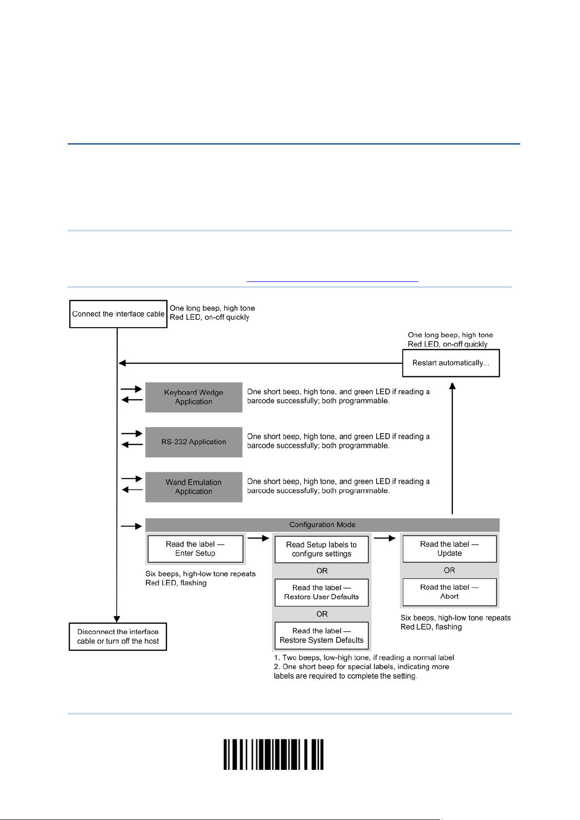
For the scanner to enter the configuration mode, you must have it read the "Enter Setup"
barcode, which can be located at the bottom of almost every even page of this manual.
The scanner will respond with six beeps and its LED indicator will become flash ing red
after reading the barcode.
Enter Setup
For configuring scanner parameters, see “Read a Setup Barcode” below.
For the scan ner to save settings and exit the configuration mode, you must have it read
the “Update” barcode, which can be located at the bottom of almost every odd page of
this manual. If you want to exit the configuration mode without saving any changes,
have the scanner read the “Abort” barcode instead.
Just li ke reading the “Enter Setup” barcode, the scanner wi ll respond with six beeps
and its LED indicator will become flashing red after reading the barcode. Wait for a
few seconds for the scanner to restart itself.
Update
Abort
6
Enter Setup
Page 20

Quick Start
DEFAULT SETTINGS
SAVE USER SETTINGS AS DEFAULTS
User
RESTORE USER DEFAULTS
Restore User
RESTORE SYSTEM DEFAULTS
Restore System
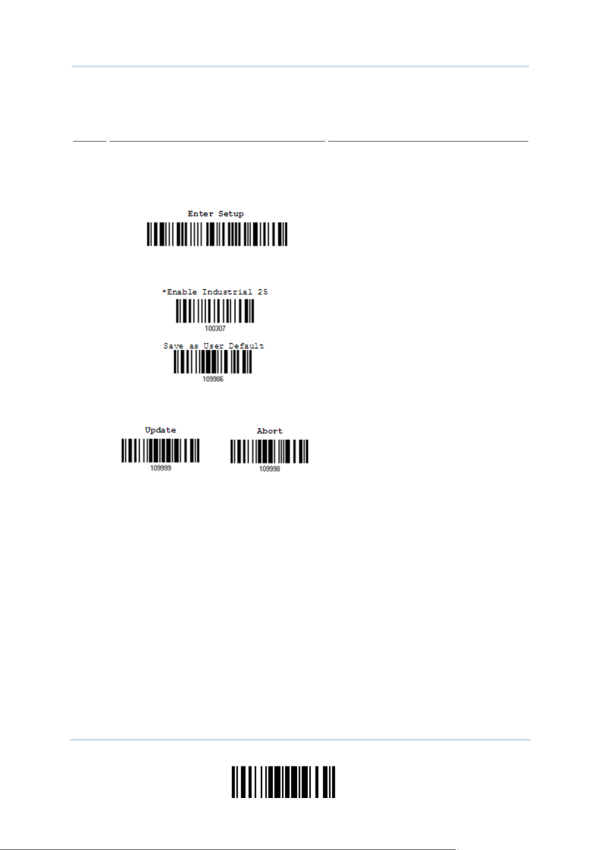
For the scanner to ke ep the customized settings as user defaults, you must have it read
the “Save as User Defaults” barcode. This is a normal setup barcode, and the scanner will
respond with two beeps (low-high tone).
After reading the “Update” barcode, the current settings will be saved as user
defaults.
Save as
Defaults
For the scanner to restore the user defaults, which you have saved earlier, you must
have it read the “Restore User Defaults” barcode. This is a normal setup barcode, and the
scanner will respond with two beeps (low-high tone).
After reading the “Update” barcode, all the param eters of the scanne r will return to
their customized values.
Defaults
For the scanner to restore the factory defaults, you must have it read the “Restore
System Defaults” barcode. This i s a normal set up barcode, an d the scan ner will resp ond
with two beeps (low-high tone).
After reading the “Update” barcode, all the paramete rs of the scanner will return to
their default values.
Defaults
Note: The system default value (if there is) for each setting i s indicated by an asterisk
“*”.
7
Update
Page 21
1500/1502 Barcode Scanner User Guide
READ A SETUP BARCODE
CONFIGURE PARAMETERS
For most of the scanner parameters, only one read is required to set them to new values.
The scanner will respond with two beeps (low-high tone) when each parameter is set
successfully.
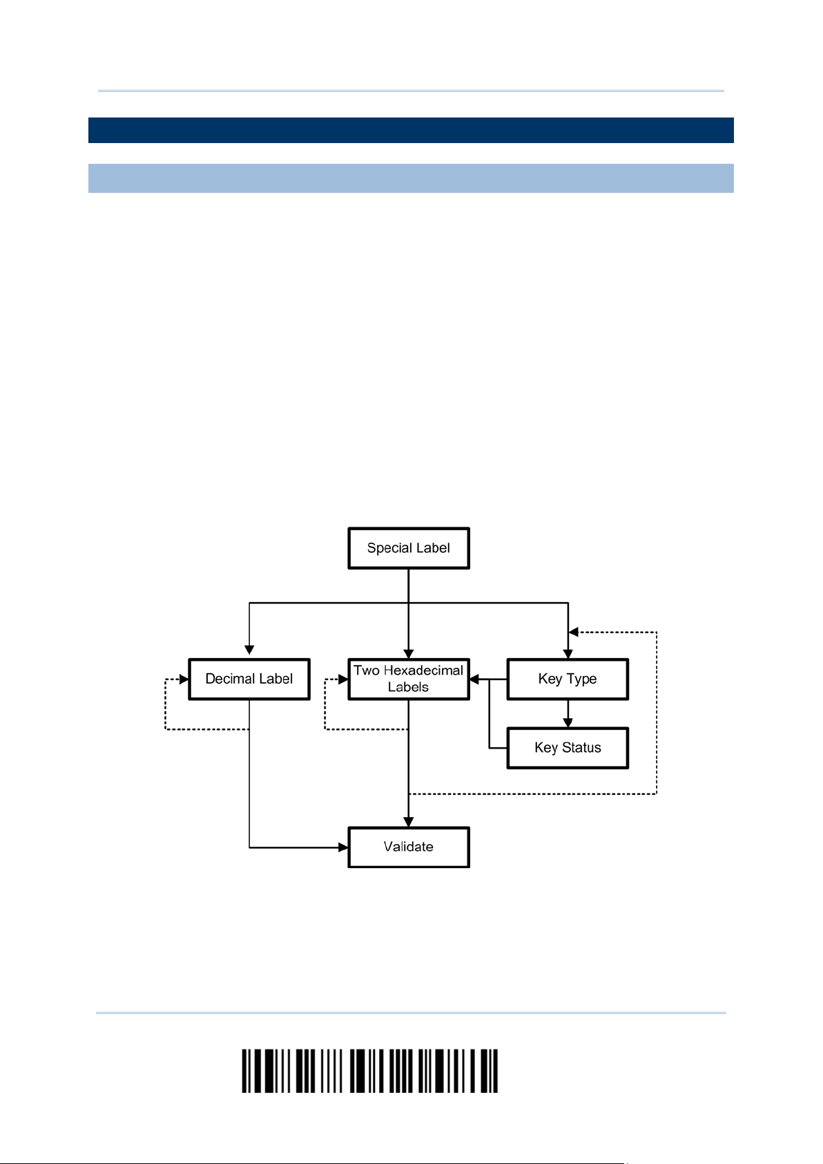
But for a number of special parameters, multiple reads are required to complete the
setting. In t his case, the scan ner will respond wi th a short beep to indicate it needs to
read more setu p barcodes. These special pa rameters may require re ading one or more
setup barcodes, such as
Numeric barcodes, say, for keyboard type, inter-character delay, length qualification
Hexadecimal barcodes, say, for character strings as prefix, suffix, etc.
When “Keyboard Wedge” is configured for interface, Key Type and Key Status will
then become applicable. You may decid e whether or n ot to change key status when
“Normal Key” is selected for Key Type.
To complete the configuration of these special parameters, it requires reading the
“Validate” barcode, and the scanner will respond with two beeps (low-high tone) to
indicate the input values are validated.
8
Enter Setup
Page 22
Quick Start
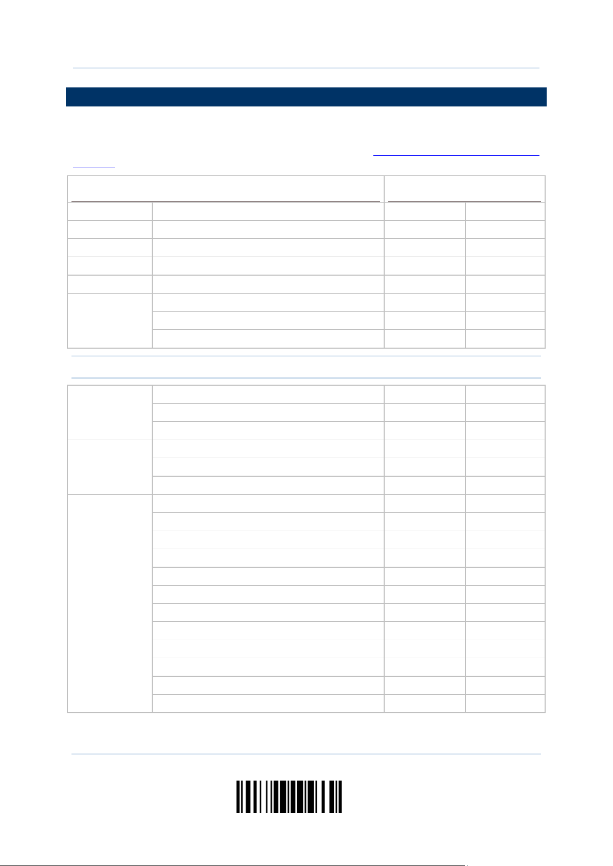
The exampl e below sho ws how to sav e your sett ings as “User Default” so that you may
Steps
Action
User Feedback if Successful
The scanner will respond with a long beep
and its LED indicator will
The scanner will respond with six beeps
low tone repeats three times), and
The scanner will respond with two beeps
normal setup
The scanner will respond with one long
restore user defaults at a later time:
1 Power on the scanner…
(high tone)
become solid red and go off qu ickly.
2 Enter the Conf ig uration Mode…
3 Read a Setup barcode…
For example,
(highits LED indicator will be flashing r e d.
(low-high tone) if reading a
barcode.
4 Exit the Configuration Mode…
Same as for Enter the Configuration Mode.
OR
5 The scanner will automatically restart itself… Same as for Power on the scanner.
* When any configuration error occurs...
beep (low tone).
9
Update
Page 23

1500/1502 Barcode Scanner User Guide
The example below shows how to set numeric parameters:
Steps
Action
User Feedback if Successful
The scanner will respond with a long beep
dicator will
The scanner will respond with six beeps
low tone repeats three times), and
The scanner will respond with two beeps
normal setup
The scanner will respond with one short
such as “Max. Length”, indicating the
“Decimal
The scanner will respond with two beeps
Normal setup
barcode
Normal setup
barcode
Special setup
barcode
Decimal barcodes
1 Power on the scanner...
(high tone) and its LED in
become solid red and go off qu ickly.
2 Enter the Conf ig uration Mode…
(highits LED indicator will become flashing red.
3 Read a Setup barcode...
For example,
(low-high tone) if reading a
barcode.
4 Exit the Configuration Mode…
beep if reading a special setup barcode
setup requires reading more barcodes.
Read the “Decimal Value” barcode(s).
Refer to Appendix IV
System”
(low-high tone) when the input values a re
validated.
Same as for Enter the Configuration Mode.
OR
5 The scanner will automatically restart itself… Same as for Power on the scanner.
10
Enter Setup
Page 24
Quick Start
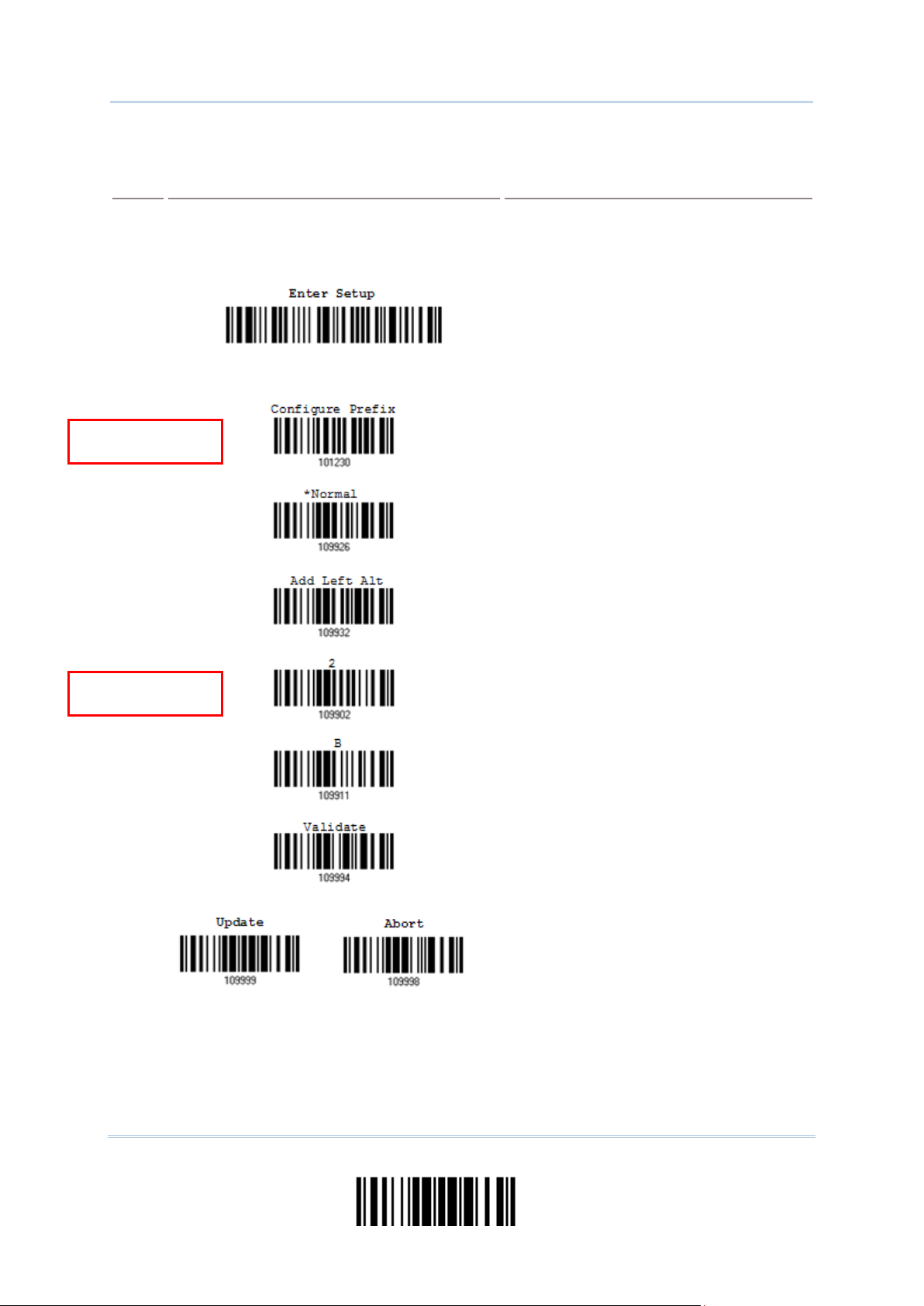
The example below shows how to set string parameters:
Steps
Action
User Feedback if Successful
beep
and its LED indicator will
The scanner will respond with six beeps
low tone repeats three times), and
The scanner will respond with one short
When “Keyboard Wedge” is configured for
e and Key Status will
then become applicable. You may decide
when
s
for the desired character string. For
Refer to Appendix IV “Hexadecimal
The scanner will respond with two beeps
Special setup
barcodes
Hexadecimal
barcodes
1 Power on the scanner... The scanner will respond with a long
(high tone)
become solid red and go off qu ickly.
2 Enter the Conf ig uration Mode…
(highits LED indicator will become flashing red.
3 Read a Setup barcode...
For example,
beep if reading a special setup barcode
such as “Prefix Co de”, ind icating the set up
requires reading more barcodes.
interface, Key Typ
4 Exit the Configuration Mode…
OR
whether or not to change key status
“Normal Key” is selected for Key Type.
Refer to Appendix III
Read the “Hexadecimal Value” barcode
example, read “2” and “B” for t he scanner
to prefix the char acter “+”.
System”
(low-high tone) when the input values ar e
validated.
Same as for Enter the Configuration Mode.
5 The scanner will automatically restart itself… Same as for Power on the scanner.
Update
11
Page 25

1500/1502 Barcode Scanner User Guide
LIST THE CURRENT SETTINGS
List settings regarding Symbology Parameters
List settings regarding Symbology Parameters
List settings regarding Symbology Parameters
The current settings of all scanner parameters can be sent, via Keyboard Wedge or
RS-232, to the host computer for user inspection. The listing includes pages as shown
below. You can select the page of interest b y having the scanner read the “List Page x”
barcode. The scanner will respond with two beeps (low-high tone) a nd send the s elected
page to the host immediately.
List settings regarding Firmware Version, Serial
Number, Interface, Buzzer, and Other Scanner
Parameters
List settings regarding Prefix, Suffix, and Length
Code Setting
List settings regarding Code ID
List settings regarding: Rea da ble S ymbologies
List Page 1
List Page 2
List Page 3
List Page 4
(1/3)
(2/3)
(3/3)
List settings regar ding Editing For m a t 1
List settings regar ding Editing For m a t 2
List settings regar ding Editing For m a t 3
List Page 5
List Page 6
List Page 7
List Page 8
List Page 9
List Page 10
12
Enter Setup
Page 26

Quick Start
List settings regar ding Editing For m a t 4
List settings regar ding Editing For mat 5
List Page 11
List Page 12
13
Update
Page 27

1500/1502 Barcode Scanner User Guide
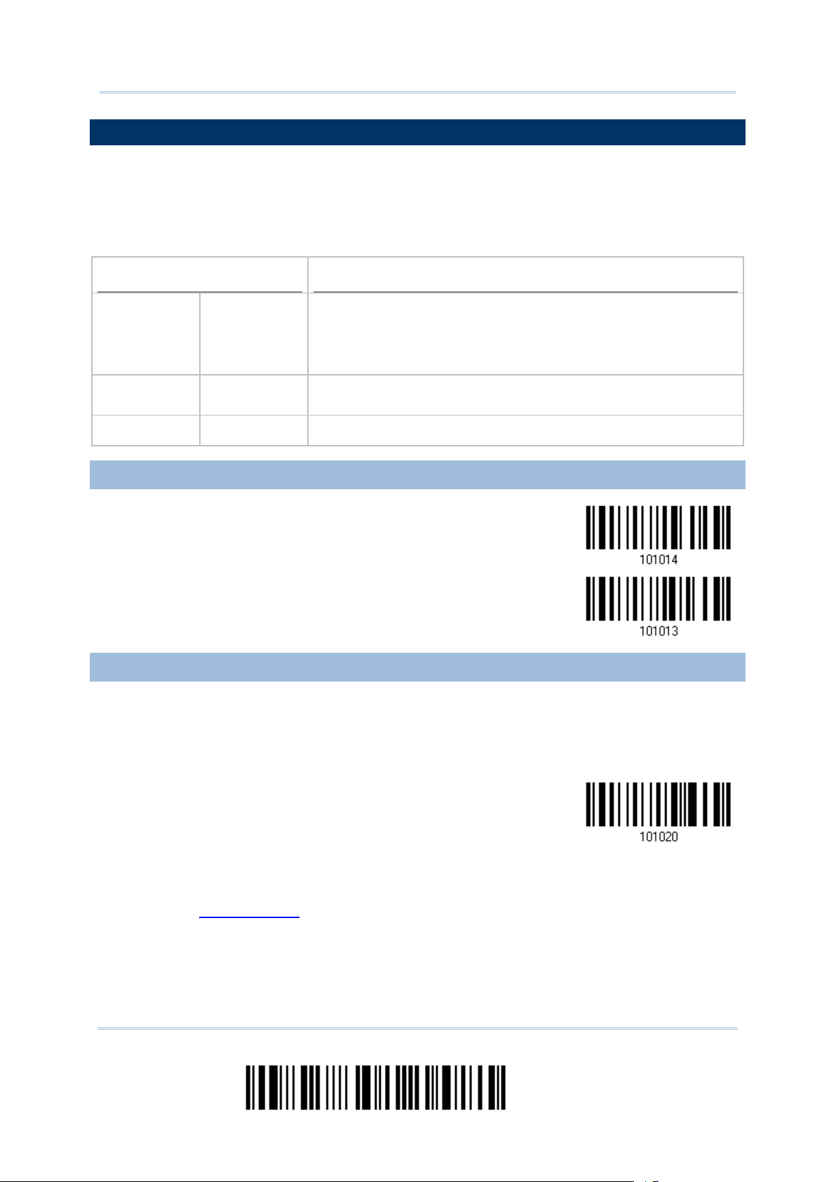
ONE-SCAN SETUP BARCODES
Scan Setup Barcode
An “One-scan S etup Barcode” does exactly what its name advertises. Scanning one such
barcode gets the setting done while saves the hassle of Enter Setup and Update
barcodes scanning. Most setting parameters are supported by One-scan Setup.
To create an “One-scan Setup Barcode”:
prefixing the setting parameter with “#@” characters
suffixing the setting parameter with “#”character
By the exampl e of the setting parameter 109952, the scanner originally needs reading
three barcodes to get it set:
Enter Setup
List Page 3
Update
With One-scan Setup Barcode #@109952#, setting is done with one scan.
One-
for 109952
Note: If the scanner reads an Once-scan Setup Barcode that changes the interface, it
automatically restarts and soun ds a long beep upon scanning, and the LED lights
on red and shortly off.
14
Enter Setup
Page 28

This chapter explains the features and usage of the ba r cod e scan n e r.
IN THIS CHAPTER
1.1 POWER-ON
1.2 TRANSMIT BUFFER
Chapter 1
UNDERSTANDING THE BARCODE SCANNER
1.1 Power-On ................................................................... 15
1.2 Transmit Buffer........................................................... 15
1.3 LED Indicator ............................................................. 16
1.4 Beeper....................................................................... 17
1.5 Send “NR” to Host ....................................................... 19
1.6 Scan Modes ................................................................ 20
1.7 Scanning Timeout ....................................................... 25
1.8 Delay between Re-read ................................................ 26
1.9 Read Redundancy for All Symblogies ............................. 27
1.10 Addon Security for UPC/EAN Barcodes ......................... 28
1.11 Auto-Sense Mode (1500/1500P Only) .......................... 29
1.12 Negative Barcodes..................................................... 30
1.13 Effective Decoding Area ............................................. 31
1.14 Cable Auto-Detection ................................................. 33
Connect the interface cable between the scanner and your computer.
If using the RS-232 cable, you must join the power supply cord to power up the
scanner.
The scanner will respond with one long beep (high tone) and its LED indicator will
become solid red and go off quickly.
The scanner i s designed to send any col lected data to a host computer one by one via
the transmit buffer (SRAM). Upon reading a barcode successfully, the scanner responds
with one short beep (high tone) and its LED indicator becomes solid green and goes off
quickly. H owever, the host comp u t er may not receive the data immediately if using a low
baud rate or waiting for handshake signal (flow control). With the transmit buffer, the
scanner can ignore the transmission status and keep on reading barcodes until the buffer
is full. When the transmit buffer is full, the scanner will respond with one long beep (low
tone) and its LED indicator will become solid red and go off quickly.
Note: The 4 KB transm it b uffer on the scann er can h ol d as many as 256 scan s based on
15
EAN-13 barcodes (equipped with 10 KB transmit buffer, 1500P can hold
approximatelt 640 scans). Data will be cl eared out once t he power ad aptor to the
RS-232 cable is removed or other interface cable is disconnected!
Update
Page 29
1500/1502 Barcode Scanner User Guide
1.3 LED INDICATOR
Scanner LED
Meaning
Power on, with one long beep (high tone, LED on for 1
1.3.1 GOOD READ LED
*Enable
Disable
1.3.2 GOOD READ LED DURATION
Good Read LED
out after
0.01~2.54 sec.
(*40 ms)
The dual-color LED on top of the scanner is used to provide user feedback. For example,
the LED becomes solid red and goes off quickly upon powering on or running out of
transmit buffer. You may tel l the di fference b y the beep s – for ex ample, you will hear a
long beep of high tone when powering on the scanner, and a long beep of l ow ton e wh en
the transmit buffer becomes full.
Red, on-off ---
second)
Transmit buffer full, with one lon g b eep ( low tone)
RS-232 connection fa ils, with two beeps (high-low tone)
--- Green, on-off Good Read, with one short beep (high ton e) and beeper pitch and
duration programmable
Red, flashing --- Configuration Mode (On/Off ratio 0.5 s: 0.5 s)
Good Read LED
Good Read LED
By default, the Good Read LED stays on for 40 milliseconds. Specify a value, ranging
from 1 to 254 in units of 10 milliseconds.
1) Read the barcode above to specify the time interval before the Good Read LED goes
off.
2) Read the “Decimal Value” barcode on page 171
Good Read LED to go off after 150 milliseconds.
3) Read the “Validate” barcode on the same page to complete this setting.
16
Time-
. For example, read “1” and “5” for the
Enter Setup
Page 30

Chapter 1 Understanding the Barcode Scanner
1.4 BEEPER
Beeping
Meaning
232 connection fails (data saved in Transmit
ired to complete the “output
Barcode Editor, with
quickly (Upon completion, same as
1.4.1 BEEPER VOLUME
The scanner has a buzzer to provide user feedback in various operating c onditions.
One long beep, high tone Power on, with r e d L ED on (1 second) and off quickly
One short beep, high tone
Programmable, default to 4 KH z
Six short beeps
High-low tone repeats three time s
Two beeps, low-high tone Setup barcode read successfully
Two beeps, high-low tone RS-
One short beep, high tone More s etup barcode required
One short beep, low tone More barcodes requ
One long beep, low tone
Two long beeps, high-low t one Multi-Barcode Mode – Buffer full
Good Read, with green LED on-off quickly
Enter Configu ration Mode, with red LED flashing
Exit Configuration Mode
Buffer), with red LED on-off quickly
sequence” requirements of Multigreen LED on-off
Good Read.)
Transmit buffer full, with red LED on-off quickly
Configuration error (Wrong barcode…)
Mute
Minimum Volume
Medium Volume
*Maximum Volume
17
Update
Page 31

1500/1502 Barcode Scanner User Guide
1.4.2 GOOD READ BEEP
Frequency
Duration
8 kHz
*4 kHz
2 kHz
1 kHz
*Shortest
Shorter
Longer
Longest
18
Enter Setup
Page 32

Chapter 1 Understanding the Barcode Scanner
1.5 SEND “NR” TO HOST
Models
Supported Output Interface
You may configure this function to have the scanner send the “NR” string to the host,
notifying that the scanner fails to read the barcode. This function works depending on
models and supported output interface as the table listed below.
1500/1500WA/1502 Keyboard Wedge
RS-232
1500P Keyboard W edge
RS-232
USB HID
USB VCOM
USB VCOM_CDC
Enable
*Disable
19
Update
Page 33

1500/1502 Barcode Scanner User Guide
1.6 SCAN MODES
Scan Mode
Start to Scan
Stop Scanning
Auto Power Off
Different scan modes are supported – select the scan mode that best suits the
requirements of a specific application. Refer to the comparison table below.
Always Press
trigger
once
Continuous
mode
Test mode
Laser mode
Auto Off mode
mode
Alternate mode
Aiming mode
Multi-Barcode
mode
Hold
trigger
Press
trigger
twice
Release
trigger
Press
trigger
once
Barcode
Timeout
being
read
Note: By default, the scan mode is set to Laser mode.
20
Enter Setup
Page 34

Chapter 1 Understanding the Barcode Scanner
1.6.1 CONTINUOUS MODE
Decoding Delay
1.6.2 TEST MODE
The scanner is always scanning.
After a successful decoding, the removal of barcode is required. It is not allowed to
proceed to decode until the decoding delay time has passed.
To decode the same barcode repeatedly, move away the barcode and put it back
again and again for scanning.
Note: Refer to “Delay between Re-read”.
Continuous Mode
Set the time interval between each decoding.
*Disable
0.5 sec
1 sec
2 sec
The scanner is always scanning.
Capable of decoding the same barcode repeatedly without removing it, for testing
purpose.
Test Mode
21
Update
Page 35

1500/1502 Barcode Scanner User Guide
1.6.3 LASER MODE
1.6.4 AUTO OFF MODE
1.6.5 AUTO POWER OFF MODE
The scanner will start scanning once the trigger is held down.
The scanning won't stop until (1) a barcode is decoded, (2) the pre-set timeout
expires, or (3) you release the trigger.
Note: Refer to “Scanning Timeout”.
*Laser Mode
The scanner will start scanning once the trigger is pressed.
The scanning won't stop until (1) a barcode is decoded, and (2) the pre-set timeout
expires.
Note: Refer to “Scanning Timeout”.
Auto Off Mode
The scanner will start scanning once the trigger is pressed.
The scanning won't stop until the pre-set timeout expires, and, the pre-set timeout
period re-counts after each successful decoding.
Note: Refer to “Delay between Re-read” and “Scanning Timeout”.
Auto Power Off Mode
22
Enter Setup
Page 36

Chapter 1 Understanding the Barcode Scanner
1.6.6 ALTERNATE MODE
1.6.7 AIMING MODE
Aiming Timeout
out
after 1~15 sec.
(*1)
e above to specify the time interval before aiming ends. (It is set to 1 by
. For example, read “1” and “0” for the scanner
The scanner will start scanning once the trigger is pressed
The scanning won't stop until you press the trigger again.
Alternate Mode
The scann er will aim a t a barcode on ce the trig ger is pressed , and start scanni ng when
the trigger is pressed again within one second.
The scanning won't stop until (1) a barcode is decoded, and (2) the pre-set timeout
expires.
Aiming Mode
You can limit the aim ing time interval ( 1~15). By default, the scanner time-out is set to 1 second.
Aiming Time-
1. Read the barcod
default.)
2. Read the “Decimal Value” barcode on page 171
to automatically shu t dow n after being idle for 10 seconds.
3. Read the “Validate” barcod e on the same page to complete this setting.
23
Update
Page 37

1500/1502 Barcode Scanner User Guide
1.6.8 MULTI-BARCODE MODE
The scanner will be scanning as long as the trigger is held down, capable of decoding one
single barcode, as well as multiple unique barcodes one at a time. While decoding a
bunch of uni que barc odes, i f a barcode is decoded twice, its subsequent decoding will be
ignored and the scanner is expecting another unique barcode.
The scanning won't stop until you release the trigger.
Multi-Barcode Mode
Note: (1) A barcode is considered unique when its Code Type or data is different from
others.
(2) Multi-Barcode Mode has nothing to do with the
Multi-Barcode Editor.
24
Enter Setup
Page 38

Chapter 1 Understanding the Barcode Scanner
1.7 SCANNING TIMEOUT
out
after 0~254 sec.
(*10)
Specify the scanning time interval (1~254 sec.; 0= Disable) when the s can mode is set
to any of the following –
Laser mode
Auto Off mode
Auto Power Off mode
Aiming mode
Scanner Time-
1) Read the barcode above to specify the time interval before the scan engine times out.
2) Read the “Decimal Value” barcode on page 171
. For example, read “1” and “5” for the
scanner to automatically shut down after being id le for 15 seconds.
3) Read the “Validate” barcode on the same page to complete this setting.
25
Update
Page 39

1500/1502 Barcode Scanner User Guide
1.8 DELAY BETWEEN RE-READ
This is al so refer red to a s th e “Bl ocki n g Ti me”, whi ch is u sed to p revent the scan ne r f rom
accidentally reading the same barcode twice when the scan mode is set to any of the
following –
Continuous mode
Auto Power Off mode
Alternate mode
100 ms
200 ms
*400 ms
800 ms
1 sec
2 sec
3 sec
5 sec
26
Enter Setup
Page 40

Chapter 1 Understanding the Barcode Scanner
1.9 READ REDUNDANCY FOR ALL SYMBLOGIES
Select the level of reading security. For example,
If "No Redundancy" is selected, one su ccessful decod ing will make th e reading valid
and induce the "READER Event".
If "Three Times" is selected, it will take a total of four consecutive successful
decoding of the same barcode to make the reading valid. The higher the reading
security is (that is, the more redundancy the user selects), the slower the reading
speed gets.
It is obvious that the more redundancy you select, the higher the reading secu rity is, and
thus, the slower the reading speed becomes. You will have to compromise between
reading security and decoding speed.
*No Redundancy
One Time
Two Times
Three Times
27
Update
Page 41

1500/1502 Barcode Scanner User Guide
1.10 ADDON SECURITY FOR UPC/EAN BARCODES
The scanner is capable of decoding a mix of UPC/EAN barcodes with and without addons.
The read redundancy (0~30 times) allows changing the number of times to decode a
UPC/EAN barc ode before transmi ssion. The more red undancy you sel ect, the higher t he
reading security is, and thus, the slower the reading speed becomes. You will have to
compromise between reading security and decoding speed.
Note: UPC/EAN Addon 2 and Addon 5 must be enabled individually for this setting to
take effect.
Addon Security Level
(*0~30)
1) Read the barcode above to specify t he read re dundanc y for UPC/EAN barcodes. (It is
set to 0 by default.)
2) Read the “Decimal Value” barcode on page 171
. For example, read “1” and “2” for the
scanner to re-read the barcode for 12 times.
3) Read the “Validate” barcode on the same page to complete this setting.
28
Enter Setup
Page 42

Chapter 1 Understanding the Barcode Scanner
1.11 AUTO-SENSE MODE (1500/1500P ONLY)
This mode is only available when you want to seat the scanner in the Auto-Sense Stan d.
When you enable this mode, it will force the scanner to apply Laser mode as the scan
mode. Howev er , it works sl ightly differen t fr om t h e o riginal Laser mode. Now th e s ca n n e r
will be expecting barcodes as long as it is seated in the Auto-Sense Stand, as shown
below. Whenever a barcode is brought within range, the scanner will be able to decode it.
Note: Auto-sen se can only b e enabled for C CD scanner an d will force i t to Laser mod e.
To stop this mode, you may remove the scanner from the stand or have the
scanner read the “Disable (Auto-Sense)” barcode below. It will return to Laser
mode. If Laser mode is not desired, proceed to select a scan mode best suits your
application.
Enable
*Disable
When the ambient light is too dim to activate the sensor, you may have the scanner read
the “High Sensitivity” barcode to improve perf ormance. Starting from firmware version
1.12, it will emit scan beam every 300 milliseconds when “High Sensitivity” is enabled.
High Sensitivity
*Normal
Note: If the ambient light is under 100 lux, we suggest that you either add lighting or
use Continuous mode instead.
29
Update
Page 43

1500/1502 Barcode Scanner User Guide
1.12 NEGATIVE BARCODES
Normally, b arcodes a re p rinted with th e color of the bars darker than that of the spaces.
But for neg ati ve b arc od es, the y a re p ri n ted i n th e opp osi t e sen se j ust l ik e nega ti ve fil ms.
The spaces of negative barcod es are printed wi th a color darker than that of the bars.
You can configure the scanner to be able to read negative barcodes.
Enable
*Disable
30
Enter Setup
Page 44

Chapter 1 Understanding the Barcode Scanner
1.13 EFFECTIVE DECODING AREA
1.13.1 POSITIONING WINDOW
By defaul t, the effec tive decod ing area i s 100% co vered by t he scan ned area. H owever,
you may narrow down the decoding area to prevent reading the wrong barcode when a
number of barcodes are printed closely. The scanner will only read barcodes that appear
in the effective decoding area.
Read the barcode “Centering On” and specify the percentage to narrow down the
decoding area. For exampl e, read “Left 10%” and th en “Right 30%” for the scan ner to
decode barcode “A” only.
Centering On
*Centering Off
31
Update
Page 45

1500/1502 Barcode Scanner User Guide
1.13.2 ADJUSTING WINDOW
Percentage for Left Half
Percentage for Right Half
*Left 50%
Left 40%
Left 30%
Left 20%
Left 10%
Right 10%
Right 20%
Right 30%
Right 40%
*Right 50%
32
Enter Setup
Page 46

Chapter 1 Understanding the Barcode Scanner
1.14 CABLE AUTO-DETECTION (1500P ONLY)
Cable Auto-Detect
Defaults
Find the interface cable provided inside the package. Connect it to the scanner. The
scanner will detect the interface automatically. Refer to
Interface.
Keyboard Wedge PCAT (US) for keyboard type
RS-232 115200 bps, 8 bits, No parity, 1 stop bit
USB USB HID and PCAT (US) for keyboard type
Note: If “USB Virtual COM” is desired, have the scanner read the setup barcodes.
Chapter 2 - Selecting Output
*Enable
Disable
33
Update
Page 47

1500/1502 Barcode Scanner User Guide
34
Enter Setup
Page 48

In order to establish a proper connection between y our computer and the scanner, we
Cable Auto-Detection
Defaults
Chapter 2
SELECTING OUTPUT INTERFACE
suggest that you follow these instructions –
1) Connect the provided interface cable between the scanner and your computer. The
scanner is capable of detecting the interface.
If using the RS-232 cable, join the power supply cord.
If using the USB cable, it is set to USB HID by default.
If “USB Virtual COM” is desired, have the scanner read the setup barcodes.
Keyboard Wedge PCAT (US) for keyboard type
RS-232 115200 bps, 8 bits, No parity, 1 stop bit
USB USB HID and PCAT (US) for keyboard type
Note: Pleas e mak e sure the wi red cab le supp orts au to-d etection . Chec k wheth er the re is
a sticker on the cable, stating “Cable Detection Supported”. The information of
available ca bles for a particul ar model is listed in the speci fication s table. R efer to
Specifications.
2) Have the scanner read the “Enter Setup” barcode to enter the configuration mode.
3) Have the scanner read the associated barcode to activate the desired interface.
See the following sections for output interfaces supported.
If you are connecting the scanner to the USB port of the host computer via USB
HID cable (part # 307), refer to 2.1 Keyboard Wedge
If you are connecting the scanner to the USB port of the host computer via USB
Virtual COM cable (part # 308), refer to 2.2 RS-232
If you are connecting the scanner to the IBM POS 4683/4694 via the converter
cable (part # 346), refer to 2.1 Keyboard Wedge
4) Have the scanner read the barcodes for related settings.
5) Have the scanner read the “Update” barcode to apply the settings and exit the
configuration mode.
35
for related settings.
related settings.
for related settings.
Update
Page 49

1500/1502 Barcode Scanner User Guide
Note: By default, the output interface is set to “Keyboard Wedge”.
IN THIS CHAPTER
Insert a pin and press it hard to release
the interface cable.
2.1 Keyboard Wedge ......................................................... 37
2.2 RS-232 ...................................................................... 47
2.3 Wand Emulation ......................................................... 52
2.4 Direct USB HID ........................................................... 56
2.5 Direct USB VCOM ........................................................ 65
2.6 Direct USB VCOM_CDC ................................................ 67
36
Enter Setup
Page 50

Chapter 2 Selecting Output Interface
2.1 KEYBOARD WEDGE
Keyboard Wedge Settings
Defaults
The Y cable allow s you to connect the scanner to the keyb oard i nput port of PC and you
may join the keyboard as well. The scanned data will be transmitted to the host keyboard
port as if it is manually entered via the keyboard.
Keyboard Type PCAT (US)
Alphabets Layout Normal
Digits Layout Normal
Capital Lock Type Normal
Capital Lock State Off
Alphabets Transmission Case-sensitive
Digits Transmission Alphanumeric keypa d
Alternate Compos ing No
Laptop Support Disable
Inter-Character Delay 0 (ms)
Inter-Function Delay 0 (ms)
37
Update
Page 51

1500/1502 Barcode Scanner User Guide
2.1.1 ACTIVATE KEYBOARD WEDGE & SELECT KEYBOARD TYPE
Activate Keyboard
Wedge & Select
Keyboard Type…
Keyboard Type
No.
Keyboard Type
No.
Keyboard Type
Once Keyboard Wedge interface is activated, a keyboard type must be selected to
complete the setting.
1) Read the aforelisted barcode to activate Keyboard Wedge.
2) Read the “Decimal Value” barcode on page 171
to select the keyboard type. Refer to
the table below for the corresponding number
3) Read the “Validate” barcode on the same page to complete this setting.
By default, the keyboard type is s et to PCAT (US). The following keyboa rd types are supported –
1 PCAT (US) 18 PS55 001-3
2 PCAT (French) 19 P S55 001-8A
3 PCAT (German) 20 PS55 002-1, 003-1
4 PCAT (Italian) 21 PS55 002-81, 003-81
5 PCAT (Swedish) 22 PS55 002-2, 003-2
6 PCAT (Norwegian) 23 PS55 002-82, 003-82
7 PCAT (UK) 24 PS55 002-3, 003-3
8 PCAT (Belgium) 25 PS55 002-8A, 003-8A
9 PCAT (Spanish) 26 IBM 3477 Type 4 (Japanese)
10 PCAT (Portug uese ) 27 PS2-30
11 PS55 A01-1 28 IBM 34XX/319X, Memorex Telex 122 Keys
12 PS55 A01-2 (Japanese) 29 User-defined table
13 PS55 A01-3 30 PCAT (Turki sh)
14 PS55 001-1 31 PCAT (Hungarian)
15 PS55 001-81 32 PCAT (Swiss)
16 PS55 001-2 33 PCAT (Danish)
17 PS55 001-82
38
Enter Setup
Page 52

Chapter 2 Selecting Output Interface
2.1.2 KEYBOARD SETTINGS
Alphabets Layout
By default, the alphabets layout is set to normal mode, also known as the standard English layout.
Alphabets Layout
Digits Layout
Capital Lock Type
Capital Lock Setting
Alphabets Transmission
Digits Transmission
Alternate Composing
Laptop Support
Select French or German keyboard layout if necessary. The scanner will make adjustments when
sending the "A", "Q", "W", "Z", "Y", and "M" characters according to this setting.
*Normal
AZERTY
QWERTZ
Note: Th is settin g only works w hen the keyb oard typ e selected is US keyboa rd, such as
PCAT (US). The Alphabets Layout and Digits Layout setting must match your
keyboard.
39
Update
Page 53

1500/1502 Barcode Scanner User Guide
US Keyboard Style – Normal
QWERTY layout, which is normally used in western countries.
French Keyboard Style – AZERTY
German Keyboard Layout – QWERTZ
Select “Lower Row” for the “Digits Layout” setting for the upper row is f or s p ec ial characters.
French layout; see below for Fr ench Keyboard Style.
Select “Upper Row” for the “Digits Lay out” setting for the lower row is for sp ec ial characters.
German layout; see below for German Keyboard S ty le.
Select “Lower Row” for the “Digits Layout” setting for the upper row is f or s p ec ial characters.
40
Enter Setup
Page 54

Chapter 2 Selecting Output Interface
Digits Layout
Select a proper layout that matches the alphabets layout. The scanner will make adjustments
Options
Description
according to this setting.
Normal Depends on the [Shift] key or [Shift Loc k] setting
Lower Row For QWERTY or QWERTZ keyboard
Upper Row For AZERTY keyboard
*Normal
Upper Row
Lower Row
Note: Thi s setting is meant to be used with the Alphabets Layout; and perhaps with the
Character Substitution setting when support to certain keyboard types (languages)
is unavailable but required.
41
Update
Page 55

1500/1502 Barcode Scanner User Guide
Capital Lock Type & Setting
In order to send the alphabets with correct case, the scanner needs to know the status of Caps
Lock on the keyboard. Incorrect settings may result in reversed case of the alphabets being
Cap Lock Type
Description
characters will be interpreted as
capital letters. However, this does not affect the number or punctuation
When enabled, the keys of alphabetic characters will be interpreted as
Capital Lock State
Description
Assuming that the status of Caps Lock on the keyboard is OFF,
transmitted characters are exactly the same as in the barcode (when
sensitive"
The scanner will automatically detect the status of Caps Lock on the
keyboard before data is transmitted; transmitted characters are exactly
r
transmitted.
Normal Normal type
Capital Lock When enabled, the keys of alphabetic
keys.
Shift Lock
capital letters. In addition, this a ffects the number or pu nctuation key s.
*Normal
Shift Lock
Capital Lock
Capital Lock OFF
"case-sensitive" is selected for Alphabets T r ansmission).
Capital Lock ON Assuming that the status of Caps Lock on the keyboard is ON, transmitted
characters are exactly the same as in the barcode ( when "caseis selected for Alphabets Transmission).
Refer to the Capital Lock T ype above.
Auto Detection
the same as in the barcode (when "case-sensitive" is selected fo
Alphabets Transmission).
Auto Detect
Capital Lock ON
42
Enter Setup
Page 56

Chapter 2 Selecting Output Interface
*Capital Lock OFF
Alphabets Transmission
sensitive, meaning that the alphabets will be
Capital Lock setting. Select [Ignore Case] to have alphabets transmitted according to the status of
Refer to 4.1 Letter Case.
By default, the alphabets transmission is casetransmitted acc or ding to their original c a se, the status of Caps Lock on the keyboard, as well as the
Caps Lock on the keyboard only.
Ignore Case
*Case-sensitive
43
Update
Page 57

1500/1502 Barcode Scanner User Guide
Digits Transmission
By default, the alphanumeric keypad is used for transmitting digits. Select “Numeric Keypad” if you
wish to use the keys on the numeric keypad.
Numeric Key
*Alphanumeric Key
Note: If you select “Numeric Keypad”, the Num Lock status of the physical keyboard
should be “ON”.
44
Enter Setup
Page 58

Chapter 2 Selecting Output Interface
ALT Composing
By default, Alternate key composing is disabled. Select [Yes] to allow emulating Alternate key code
of a specific keyboard character. Fo r example, [Alt] + [065] will b e sent to host for the characte r
Laptop Support
By default, laptop support is disabled. It is suggested to enable this feature if you connect the
“A” regardless the keyboard ty pe y ou are using.
Yes
*No
wedge cable to a laptop without an external keyboard being inter-connected.
Enable
*Disable
45
Update
Page 59

1500/1502 Barcode Scanner User Guide
2.1.3 INTER-CHARACTER DELAY
Character
2.1.4 INTER-FUNCTION DELAY
Function
By default, the inter-character delay is set to zero. Specify a value, ranging from 0 to
254 in units of millisecond, to match the computer response time of the keyboard
interface. Such delay time is inserted between every character being transmitted. The
longer the delay time is, the slower the transmission speed will be.
InterDelay… (*0~254)
1) Read the barcode above to specify the inter-character delay.
2) Read the “Decimal Value” barcode on page 171
for the d esired int er-character d elay
(millisecond).
3) Read the “Validate” barcode on the same page to complete this setting.
By defaul t, the i nt er-function delay is set to zero. Specify a value, ranging from 0 to 254
in units of millisecond, to match the computer response time of the keyboard interface.
Such delay time is inserted between every function code (0x01 ~ 0x1F) being
transmitted. The longer the delay time is, the slower the transmission speed will be.
Inter-
Delay… (*0~254)
1) Read the barcode above to specify the inter-function delay.
2) Read the “Decimal Value” barcode on page 171
(millisecond).
3) Read the “Validate” barcode on the same page to complete this setting.
for the desired inter-function delay
46
Enter Setup
Page 60

Chapter 2 Selecting Output Interface
2.2 RS-232
RS-232 Settings
Defaults
2.2.1 ACTIVATE RS-232 INTERFACE
232
2.2.2 BAUD RATE
Use the RS-232 cable to connect the scanner t o the s erial p ort of PC and join the power
adaptor to the RS-232 connector. Th e associated RS-232 pa rameters must match those
configured on the computer. The scanned data will be transmitted to the serial port.
Baud Rate, Data Bit, Parity, Stop Bit 9600 bps, 8 bits, No parity, 1 stop bit
Flow Control None
Inter-Character Delay 0 (ms)
Inter-Function Delay 0 (ms)
ACK/NAK Timeout 0
ACK/NAK Beep Disable
Activate RS-
Interface
115200 bps
57600 bps
38400 bps
19200 bps
*9600 bps
4800 bps
47
Update
Page 61

1500/1502 Barcode Scanner User Guide
2.2.3 DATA BITS
2.2.4 PARITY
2.2.5 STOP BIT
2400 bps
1200 bps
600 bps
*8 bits
7 bits
*No parity
Even
Odd
2 stop bits
*1 stop bit
48
Enter Setup
Page 62

Chapter 2 Selecting Output Interface
2.2.6 FLOW CONTROL
Options
Description
The scanner will ac tivate the RTS signal upon pow e r ing on. After each good
, the scanner will then wait for the CTS signal to become active. Data
The RTS signal will be activated after each good read. The scanner will
Data will not be sent until
It works the same as the Data Ready flow control except that the RTS
By default, there is no flow control in use. Select the flow control (handshake) method.
No No flow control
Scanner Ready
read
will not be sent until the CTS signal bec om es active.
Data Ready
then wait for the CTS signal to become active.
the CTS signal becomes active.
Inverted Data Ready
signal level is inve r ted.
*None
Scanner Ready
Data Ready
Invert Data Ready
49
Update
Page 63

1500/1502 Barcode Scanner User Guide
2.2.7 INTER-CHARACTER DELAY
Character
2.2.8 INTER-FUNCTION DELAY
Function
By default, the inter-character delay i s zero. Specify a value, ra nging from 0 to 254 in
units of millisecond, to match the computer response time. Such delay time is inserted
between eve ry characte r being tran smitted. Th e longer the d elay time i s, the slower t he
transmission speed will be.
InterDelay… (*0~254)
1) Read the barcode above to specify the inter-character delay.
2) Read the “Decimal Value” barcode on page 171
for the d esired int er-character d elay
(millisecond).
3) Read the “Validate” barcode on the same page to complete this setting.
By defaul t, the i nt er-fun cti on del ay i s set to zero . Sp ecify a val ue, ranging from 0 to 254
in units of millisecond, to match the computer response time of the keyboard interface.
Such delay time is inserted between every function code (0x01 ~ 0x1F) being
transmitted. The longer the delay time is, the slower the transmission speed will be.
Inter-
Delay… (*0~254)
1) Read this barcode above to specify the inter-function delay.
2) Read the “Decimal Value” barcode on page 171
(millisecond).
3) Read the “Validate” barcode on the same page to complete this setting.
for the desired inter-function delay
50
Enter Setup
Page 64

Chapter 2 Selecting Output Interface
2.2.9 ACK/NAK TIMEOUT
out
ACK/NAK Error Beep
By default, the scanner sends data to the host without waiting for an ACK/NAK response
before sending more dat a . S pecify a value, ra nging from 1 to 99 in units of 0.1 second. If
no response within the specified period of time, the scanner will attempt to send the
same data two more times. If all three attempts fail without any notification, data loss
will occur.
ACK/NAK Time-
after … (*0~99)
1) Read the barcode above to specify the time interval for the scanner to send data and
wait for a response from the host.
2) Read the “Decimal Value” barcode on page 171
. For example, read “1” and “0” for the
scanner to automatically shut down after being id le for 1 second.
3) Read the “Validate” barcode on the same page to complete this setting.
Enable Error Beep
*Disable Error Beep
Note: We suggest enabling the error beep so that you will be notified of such data loss
and have the scanner re-read data.
51
Update
Page 65

1500/1502 Barcode Scanner User Guide
2.3 WAND EMULATION
Wand Emulation Settings
Defaults
2.3.1 ACTIVATE WAND EMULATION
Activate
2.3.2 NORMAL STATE
2.3.3 BAR STATE
The wand emulation cable allows you to connect the scanner to a data terminal that i s
expecting input from a wand scanner. Note that this function doesn’t support 1500P.
Normal State Low
Bar State High
Module Time 1 (ms)
Margin Time 20 (ms)
Output Format Normal Output
Wand Emulation
By default, the signal level is set to "Low" for the normal state when not transmitting any
barcode image (= white spaces in a barcode).
High
*Low
By default, the signal level is set to "High" for a bar when transmitting a barcode image
(= dark bars in a barcode).
*High
Low
52
Enter Setup
Page 66

Chapter 2 Selecting Output Interface
2.3.4 MODULE TIME
By default, it is set to 1 mi llisecond as th e time span for bar and space modu les. Select
other value f or the module t ime, in units of micro-second or millisecond.
250 µs
500 µs
*1 ms
1.5 ms
2 ms
3 ms
4 ms
5 ms
53
Update
Page 67

1500/1502 Barcode Scanner User Guide
2.3.5 MARGIN TIME
By default, it is set 20 milliseconds as the time span for the change in state for bar and
space modules. Select other value for the margin time.
5 ms
10 ms
*20 ms
30 ms
40 ms
60 ms
80 ms
100 ms
Note: Margin Time is applied only when th e signal level for Normal State and Bar State is
the same.
54
Enter Setup
Page 68

Chapter 2 Selecting Output Interface
2.3.6 OUTPUT FORMAT
By default, the output format is set to "Normal Output" to send data to the terminal in
the format of the scanned barcodes, except for GS1 DataBar. By scanning the Code 128
Output barcode below, users can dete rmine al l scann ed barcod es to be send to the data
terminal in the format of Code 128.
*Normal Output
Code 128 Output
55
Update
Page 69

1500/1502 Barcode Scanner User Guide
2.4 DIRECT USB HID
HID Settings
Defaults
2.4.1 ACTIVATE USB HID & SELECT KEYBOARD TYPE
Activate
Direct USB HID &
Select Keyboard
USB HID
No.
Keyboard Type
No.
Keyboard Type
For USB HID, connect the scanner to the USB port of PC. Run any text editor on the
computer, and the scanned data will be transmitted to the computer.
Keyboard Type PCAT (US)
Digits Layout Normal
Capital Lock Type Normal
Capital Lock State Off
Alphabets Transmission Case-sensitive
Digits Transmission Alphanumeric keypa d
Kanji Transmission Disable
Inter-Character Delay 0 (ms)
Inter-Function Delay 0 (ms)
When USB HID in terface is acti vated, it will h ave to select a keyboa rd type to compl ete
this setting.
Type…
1) Read the barcode above to activate USB HID and select a key board type.
2) Read the “Decimal Value” barcode on page 171
. Refer to the table below for the
number of desired keyboard type.
3) Read the “Validate” barcode on the same page to complete this setting.
By default, the keyboard type is set to PCAT (US ). Th e f ollow in g keyboard types are supported —
64 PCAT (US) 72 PCAT (Spanish)
65 PCAT (French) 73 PCAT (Port ug uese )
66 PCAT (German) 74 PS55 A01-2 (Japanese)
67 PCAT (Italy) 75 User-defined table
68 PCAT (Swed i s h) 76 PCAT (Turkish)
69 PCAT (Norwegian) 77 PCAT (Hungarian)
70 PCAT (UK) 78 PCAT (Swiss German)
56
Enter Setup
Page 70

Chapter 2 Selecting Output Interface
71 PCAT (Bel g ium) 79 PCAT (Danish)
2.4.2 KEYBOARD SETTINGS
Alphabets Layout
By default, the alphabets layout is set to normal mode, also known as the standard English layout.
Alphabets Layout
Digits Layout
Capital Lock Type
Capital Lock Setting
Alphabets Transmission
Digits Transmission
Kanji Transmission
Select French or German keyboard layout if necessary. The scanne r will make adjustme nts when
sending the "A", "Q", "W", "Z", "Y", and "M" characters according to this setting.
*Normal
AZERTY
QWERTZ
Note: Th is settin g only works w hen the keyb oard typ e selected is US keyboa rd, such as
PCAT (US). The Alphabets Layout and Digits Layout setting must match your
keyboard.
57
Update
Page 71

1500/1502 Barcode Scanner User Guide
US Keyboard Style – Normal
French Keyboard Style – AZERTY
German Keyboard Layout – QWERTZ
QWERTY layout, which is normally used in western countries.
Select “Lower Row” for the “Digits Layout” setting for the upper row is for special characters.
French layout; see below for French Keyboard Style.
Select “Upper Row” for the “Digits Layout” setting for the lower row is for special characters.
German layout; see below for German Keyboard Style.
Select “Lower Row” for the “Digits Layout” setting for the upper row is for special characters.
58
Enter Setup
Page 72

Chapter 2 Selecting Output Interface
Digits Layout
Select a proper layout that matches the alphabets layout. The scanner
will make adjustments
Options
Description
according to this setting.
Normal Depends on the [Shift] key or [Shift Loc k] setting
Lower Row For QWERTY or QWERTZ keyboard
Upper Row For AZERTY keyboard
*Normal
Upper Row
Lower Row
Note: This setting is meant to be used with the Character Substitution setting when
support to certain keyboard types (languages) is unav ailable but required.
59
Update
Page 73

1500/1502 Barcode Scanner User Guide
Capital Lock Type & Setting
In order to send the alphabe ts with correct case, the scanner
needs to know the status of Caps
Lock on the keyboard. Incorrect settings may result in reversed case of the alphabets being
Cap Lock Type
Description
terpreted as
capital letters. However, this does not affect the number or punctuation
When enabled, the keys of alphabetic characters will be interpreted as
Capital Lock State
Description
Assuming that the status of Caps Lock on the keyboard is OFF,
transmitted characters are exactly the same as in the barcode (when
sensitive"
The scanner will automatically detect the status of Caps Lock on the
keyboard before data is transmitted; transmitted characters are exactly
sensitive" is selected for
transmitted.
Normal Normal type
Capital Lock When enabled, the keys of alphabetic characters will be in
keys.
Shift Lock
capital letters. In addition, this a ffects the number or pu nctuation keys.
*Normal
Shift Lock
Capital Lock
Capital Lock OFF
"case-sensitive" is selec ted for Alphabets Transmission).
Capital Lock ON Assuming that the status of Caps Lock on the keyboard is ON, transmitted
characters are exactly the same as in the barcode ( when "caseis selected for Alphabets Transmission).
Refer to the Capital Lock Type above.
Auto Detection
the same as in the barcode (when "caseAlphabets Transmission).
Auto Detect
Capital Lock ON
60
Enter Setup
Page 74

Chapter 2 Selecting Output Interface
*Capital Lock OFF
Alphabets Transmission
sensitive, meaning that the alphabets will be
Capital Lock setting. Select [Ignore Case] to have alphabets transmitted according to the status of
Refer to 4.1 Letter Case.
By default, the alphabets transmission is casetransmitted acc or ding to their original c a se, the status of Ca ps L oc k on the keyboard, as well a s the
Caps Lock on the keyboard only.
Ignore Case
*Case-sensitive
61
Update
Page 75

1500/1502 Barcode Scanner User Guide
Digits Transmission
By default, the al
phanumeric keypad is used for transmitting digits. Select “Numeric Keypad” if you
Kanji Transmission
By default, the alphanumeric keypad is used for transmitting digits. Select “Numeric Keypad” if you
wish to use the keys on the numeric keypad.
Numeric Key
*Alphanumeric Key
Note: If you select “Numeric Keypad”, the Num Lock status of the physical keyboard
should be “ON”.
wish to use the keys on the numeric keypad.
Enable
*Disable
62
Enter Setup
Page 76

Chapter 2 Selecting Output Interface
2.4.3 INTER-CHARACTER DELAY
Character
2.4.4 INTER-FUNCTION DELAY
Function
By default, the inter-character del ay is set to zero. Specify a value, ranging from 0 to
254 in units of millisecond, to match the computer response time of the keyboard
interface. Such delay time is inserted between every character being transmitted. The
longer the delay time is, the slower the transmission speed will be.
InterDelay… (*0~254)
1) Read the barcode above to specify the inter-character delay.
2) Read the “Decimal Value” barcode on page 171
for the d esired int er-character d elay
(millisecond).
3) Read the “Validate” barcode on the same page to complete this setting.
By default, the i nt er-function delay is set to zero. Speci fy a valu e, ran gi ng from 0 to 254
in units of millisecond, to match the computer response time of the keyboard interface.
Such delay time is inserted between every function code (0x01 ~ 0x1F) being
transmitted. The longer the delay time is, the slower the transmission speed will be.
Inter-
Delay… (*0~254)
1) Read the barcode above to specify the inter-function delay.
2) Read the “Decimal Value” barcode on page 171
(millisecond).
3) Read the “Validate” barcode on the same page to complete this setting.
for the d esired int er-character d elay
63
Update
Page 77

1500/1502 Barcode Scanner User Guide
2.4.5 HID CHARACTER TRANSMIT MODE
2.4.6 SPECIAL KEYBOARD FEATURE
By default, USB HID interface sends data to the host in batch. Have the scanner read the
“By Character” barcode to process data one character at a time.
*Batch Processing
By Character
By default, the special keyboard feature is based on the factory definition. You can decide
whether to apply the special keyboard feature. Refer to Keyboard Wedge Table
.
*Apply
Bypass
64
Enter Setup
Page 78

Chapter 2 Selecting Output Interface
2.5 DIRECT USB VCOM
2.5.1 ACTIVATE USB VIRTUAL COM
Activate Direct USB
2.5.2 INTER-FUNCTION DELAY
Function
For USB Vi rt ual COM , c onn ect th e sc an ner to th e US B p ort of PC . Ru n Hy p erTe rmi nal .exe
on the computer, and the scanned data will be transmitted to the computer.
Note: If using USB Virtual COM for the first time, you must install the accompanying
driver beforehand. Driver version 5.4 or later is required. Please remove older
versions! Instead, users can also decide to use the USB communication device
class (CDC) driver by selecting Direct USB VCOM_CDC. Refer to
2.6 Direct USB
VCOM_CDC.
Virtual COM
By default, the i nt er-function delay is set to zero. Specify a value, ranging from 0 to 254
in units of millisecond, to match the computer response time of the keyboard interface.
Such delay time is inserted between every function code (0x01 ~ 0x1F) being
transmitted. The longer the delay time is, the slower the transmission speed will be.
Inter-
Delay… (*0~254)
1) Read the barcode above to specify the inter-function delay.
2) Read the “Decimal Value” barcode on page 171
for the d esired int er-character d elay
(millisecond).
3) Read the “Validate” barcode on the same page to complete this setting.
65
Update
Page 79

1500/1502 Barcode Scanner User Guide
2.5.3 ACK/NAK TIMEOUT
out
ACK/NAK Error Beep
By default, the scanner sends data to the host without waiting for an ACK/NAK response
before sending more data. Specify a value, ranging from 1 to 99 in units of 0.1 second. If
no response within the specified period of time, the scanner will attempt to send the
same data two more times. If all three attempts fail without any notification, data loss
will occur.
ACK/NAK Time-
after … (*0~99)
1) Read the barcode above to specify the time interval for the scanner to send data and
wait for a response from the host.
2) Read the “Decimal Value” barcode on page 171
. For example, read “1” and “0” for the
scanner to automatically shut down after being id le for 1 second.
3) Read the “Validate” barcode on the same page to complete this setting.
Enable Error Beep
*Disable Error Beep
Note: We suggest enabling the error beep so that you will be notified of such data loss
and have the scanner re-read data.
66
Enter Setup
Page 80

Chapter 2 Selecting Output Interface
2.6 DIRECT USB VCOM_CDC
2.6.1 ACTIVATE USB VCOM_CDC
Activate Direct USB
2.6.2 INTER-FUNCTION DELAY
Function
For USB Virtual COM, connect the scanner to the USB port of PC. Run HyperT ermi nal .exe
on the computer, and the scanned data will be transmitted to the computer.
Note: If using USB Virtual COM for the first time, you must install the accompanying USB
VCOM_CDC driver beforehand.
Virtual COM
By default, the i nt er-function delay is set to zero. Specify a value, ranging from 0 to 254
in units of millisecond, to match the computer response time of the keyboard interface.
Such delay time is inserted between every function code (0x01 ~ 0x1F) being
transmitted. The longer the delay time is, the slower the transmission speed will be.
Inter-
Delay… (*0~254)
1) Read the barcode above to specify the inter-function delay.
2) Read the “Decimal Value” barcode on pag e 171
for the d esired int er-character d elay
(millisecond).
3) Read the “Validate” barcode on the same page to complete this setting.
67
Update
Page 81

1500/1502 Barcode Scanner User Guide
2.6.3 ACK/NAK TIMEOUT
out
ACK/NAK Error Beep
By default, the scanner sends data to the host without waiting for an ACK/NAK response
before sending more data. Specify a value, ranging from 1 to 99 in units of 0.1 second. If
no response within the specified period of time, the scanner will attempt to send the
same data two m ore times. If all th ree attempts fail without any notification, data loss
will occur.
ACK/NAK Time-
after … (*0~99)
1) Read the barcode above to specify the time interval for the scanner to send data and
wait for a response from the host.
2) Read the “Decimal Value” barcode on page 171
. For example, read “1” and “0” for the
scanner to automatically shut down after being id le for 1 second.
3) Read the “Validate” barcode on the same page to complete this setting.
Enable Error Beep
*Disable Error Beep
Note: We suggest enabling the error beep so that you will be notified of such data loss
and have the scanner re-read data.
68
Enter Setup
Page 82

In this chapter, a brief on the symbology settings is provided for your reference.
IN THIS CHAPTER
3.19 UPC-E .................................................................... 108
Chapter 3
CHANGING SYMBOLOGY SETTINGS
3.1 Codabar ..................................................................... 70
3.2 Code 25 – Industrial 25 ............................................... 72
3.3 Code 25 – Interleaved 25 ............................................. 75
3.4 Code 25 – Matrix 25 .................................................... 78
3.5 Code 39 ..................................................................... 81
3.6 Code 93 ..................................................................... 83
3.7 Code 128 ................................................................... 83
3.8 EAN-8........................................................................ 84
3.9 EAN-13 ...................................................................... 86
3.10 GS1-128 (EAN-128) .................................................. 91
3.11 ISBT 128 .................................................................. 93
3.12 MSI ......................................................................... 94
3.13 French Pharmacode ................................................... 96
3.14 Italian Pharmacode ................................................... 97
3.15 Plessey .................................................................... 98
3.16 GS1 DataBar (RSS Family) ......................................... 99
3.17 Telepen .................................................................. 104
3.18 UPC-A .................................................................... 106
69
Update
Page 83

1500/1502 Barcode Scanner User Guide
3.1 CODABAR
3.1.1 SECURITY LEVEL
3.1.2 START/STOP CHARACTERS SELECTION
*Enable
Disable
Security Level renders more decoding accuracy giving consideration to barcodes’ print
quality. The scanner allows you to change t he CODABAR secu rity level between high or
normal level.
* High
Normal
Select one of the four different start/stop character pairs –
* abcd/abcd
abcd/tn*e
ABCD/ABCD
ABCD/TN*E
70
Enter Setup
Page 84

Chapter 3 Changing Symbology Settings
3.1.3 START/STOP TRANSMISSION
Transmit Start/Stop
3.1.4 CLSI CONVERSION
Decide whether to include the start/stop characters in the data being transmitted.
Characters
*Do Not Transmit
When enabled, the CLSI editing strips the start/stop characters and inserts a space a fter
the first, fifth, and tenth characters o f a 14-character Codabar barcode.
Apply CLSI Editing
*Do Not Apply
Note: The 14-character barcode length does not include start/stop characters.
71
Update
Page 85

1500/1502 Barcode Scanner User Guide
3.2 CODE 25 – INDUSTRIAL 25
3.2.1 SELECT START/STOP PATTERN
*Industrial 25
Interleaved 25
Matrix 25
*Enable
Disable
This decides the readability of all 2 of 5 symbology variants. For example, flight tickets
actually use an Industrial 2 of 5 barcode but with Interleaved 2 of 5 start/stop pattern. In
order to read this barcode, the start/stop pattern selection parameter of Industrial 2 of 5
should set to "Interleaved 25".
Start/Stop Pattern
Start/Stop Pattern
Start/Stop Pattern
72
Enter Setup
Page 86

Chapter 3 Changing Symbology Settings
3.2.2 VERIFY CHECK DIGIT
3.2.3 TRANSMIT CHECK DIGIT
*Transmit
Industrial 25
Check Digit
Decide whether to verify the check digit. If incorrect, the barcode will not be accepted.
Verify Industrial 25
Check Digit
*Do Not Verify
Decide whether to include the check digit in the da ta being transmitted.
Do Not Transmit
73
Update
Page 87

1500/1502 Barcode Scanner User Guide
3.2.4 CODE LENGTH QUALIFICATION
*Enable Max./Min.
Enable Fixed
Min. Length (*4) or
To prevent the "short scan" error, define the "Length Qualification" settings to ensure
that the correct barcode is read by qualifying the a llowable code length.
If "Max/Min Length" is selected, the maximum length and the minimum length must
be specified. It only accepts those barcodes with lengths that fall between max/min
lengths specified.
If “Fixed Length” is selected, up to 2 fixed lengths can be specified.
1) Read the barcode t o enabl e either Max. /Min. Length qualification or Fixed Length(s)
qualification.
Length (0~127)…
Length(s)…
2) Read the barcode for Max. Length or Fixed Length 1, and fo llow steps 3~4.
Repeat steps 2~4 for Min. Length or Fixed Length 2.
Max. Length (*127) or
Fixed Length 1
Fixed Length 2
3) Read the “Decimal Value” barcode on page 171
for the desired length.
4) Read the “Validate” barcode on the same page to complete this setting.
74
Enter Setup
Page 88

Chapter 3 Changing Symbology Settings
3.3 CODE 25 – INTERLEAVED 25
3.3.1 SELECT START/STOP PATTERN
l 25
*Interleaved 25
Matrix 25
*Enable
Disable
This decides the readability of all 2 of 5 symbology variants. For exampl e, flight tickets
actually use an Industrial 2 of 5 barcode but with Interleaved 2 of 5 start/stop pattern. In
order to read this barcode, the start/stop pattern selection parameter of Industrial 2 of 5
should set to "Interleaved 25".
Industria
Start/Stop Pattern
Start/Stop Pattern
Start/Stop Pattern
75
Update
Page 89

1500/1502 Barcode Scanner User Guide
3.3.2 VERIFY CHECK DIGIT
Verify
Interleaved 25
Check Digit
3.3.3 TRANSMIT CHECK DIGIT
*Transmit
Interleaved 25
Check Digit
Decide whether to verify the check digit. If incorrect, the barcode will not be accepted.
*Do Not Verify
Decide whether to include the check digit in the da ta being transmitted.
Do Not Transmit
76
Enter Setup
Page 90

Chapter 3 Changing Symbology Settings
3.3.4 CODE LENGTH QUALIFICATION
in.
Enable Fixed
Min. Length (*4) or
To prevent the "short scan" error, define the "Length Qualification" settings to ensure
that the correct barcode is read by qualifying the a llowable code length.
If "Max/Min Length" is selected, the maximum length and the minimum length must
be specified. It only accepts those barcodes with lengths that fall between max/min
lengths specified.
If “Fixed Length” is selected, up to 2 fixed lengths can be specified.
1) Read the barcode t o enabl e either Max. /Mi n. Length qualification or Fixed Length(s)
qualification.
*Enable Max./M
Length (0~127)…
Length(s)…
2) Read the barcode for Max. Length or Fixed Length 1, and fo llow steps 3~4.
Repeat steps 2~4 for Min. Length or Fixed Length 2.
Max. Length (*126) or
Fixed Length 1
Fixed Length 2
3) Read the “Decimal Value” barcode on page 171
for the desired length.
4) Read the “Validate” barcode on the same page to complete this setting.
77
Update
Page 91

1500/1502 Barcode Scanner User Guide
3.4 CODE 25 – MATRIX 25
3.4.1 SELECT START/STOP PATTERN
Industrial 25
Interleaved 25
*Matrix 25
Enable
*Disable
This decides the readability of all 2 of 5 symbology variants. For example, flight tickets
actually use an Industrial 2 of 5 barcode but with Interleaved 2 of 5 start/stop pattern. In
order to read t hi s barcode, the start/stop pattern selection parameter of Industrial 2 of 5
should set to "Interleaved 25".
Start/Stop Pattern
Start/Stop Pattern
Start/Stop Pattern
78
Enter Setup
Page 92

Chapter 3 Changing Symbology Settings
3.4.2 VERIFY CHECK DIGIT
Verify Matrix 25
3.4.3 TRANSMIT CHECK DIGIT
ix 25
Decide whether to verify the check digit. If incorrect, the barcode will not be accepted.
Check Digit
*Do Not Verify
Decide whether to include the check digit in the da ta being transmitted.
*Transmit Matr
Check Digit
Do Not Transmit
79
Update
Page 93

1500/1502 Barcode Scanner User Guide
3.4.4 CODE LENGTH QUALIFICATION
*Enable Max./Min.
Enable Fixed
Min. Length (*4) or
To prevent the "short scan" error, define the "Length Qualification" settings to ensure
that the correct barcode is read by qualifying the a llowable code length.
If "Ma x/Min Length" is selected, the maximum length and the minimum length must
be specified. It only accepts those barcodes with lengths that fall between max/min
lengths specified.
If “Fixed Length” is selected, up to 2 fixed lengths can be specified.
1) Read the barcode t o enabl e either Max. /Mi n. Length qualification or Fixed Length(s)
qualification.
Length (0~127)…
Length(s)…
2) Read the barcode for Max. Length or Fixed Length 1, and fo llow steps 3~4.
Repeat steps 2~4 for Min. Length or Fixed Length 2.
Max. Length (*127) or
Fixed Length 1
Fixed Length 2
3) Read the “Decimal Value” barcode on page 171
for the desired length.
4) Read the “Validate” barcode on the same page to complete this setting.
80
Enter Setup
Page 94

Chapter 3 Changing Symbology Settings
3.5 CODE 39
3.5.1 TRANSMIT START/STOP CHARACTERS
Transmit Code 39
Start/Stop
Characters
3.5.2 VERIFY CHECK DIGIT
Verify Code 39
*Enable
Disable
Decide whether to include the start/stop characters in the data being transmitted.
*Do Not Transmit
Decide whether to verify check digit. If incorrect, the barcode will not be accepted.
Check Digit
*Do Not Verify
81
Update
Page 95

1500/1502 Barcode Scanner User Guide
3.5.3 TRANSMIT CHECK DIGIT
*Transmit Code 39
3.5.4 STANDARD/FULL ASCII CODE 39
3.5.5 SECURITY LEVEL
Normal
Decide whether to include the check digit in the data being transmitted.
Check Digit
Do Not Transmit
Decide whether to support Code 39 Full ASCII that includes all the alphanumeric and
special characters.
Code 39 Full ASCII
*Standard Code 39
Security Level renders more decoding accuracy giving consideration to barcodes’ print
quality. Decide the security level for reading Code 39 barcodes.
*High
82
Enter Setup
Page 96

Chapter 3 Changing Symbology Settings
3.6 CODE 93
3.7 CODE 128
3.7.1 SECURITY LEVEL
*Enable
Disable
*Enable
Disable
Security Level renders more decoding accuracy giving consideration to barcodes’ print
quality. Decide the security level for reading Code 128 barcodes.
*High
Normal
83
Update
Page 97

1500/1502 Barcode Scanner User Guide
3.8 EAN-8
EAN-8
8
EAN-8 Addon 2
EAN-8 Addon 5
*Enable EAN-
(No Addon)
Disable
Enable EAN-8 Addon 2
*Disable
Enable EAN-8 Addon 5
*Disable
84
Enter Setup
Page 98

Chapter 3 Changing Symbology Settings
3.8.1 CONVERT TO EAN-13
8 to
3.8.2 TRANSMIT CHECK DIGIT
8
3.8.3 CONVERSION FORMAT
Decide whether to expand the read EAN-8 barcode, as well as its addons, into EAN-13.
After conversion, the data follows EAN-13 format and is affected by EAN-13
programming selections (e.g. Check Digit).
Convert EAN-
EAN-13
*Do Not Convert
Decide whether to include the check digit in the da ta being transmitted.
*Transmit EAN-
Check Digit
Do Not Transmit
When converting EAN-8 to EAN-13, you can scan the barcode below to decide conve rsi on
in default or GTIN-13 format.
*Default Format
GTIN-13 Format
85
Update
Page 99

1500/1502 Barcode Scanner User Guide
3.9 EAN-13
EAN-13
13
EAN-13 Addon 2
EAN-13 Addon 5
*Enable EAN-
(No Addon)
Disable
Enable EAN-13 Addon 2
*Disable
Enable EAN-13 Addon 5
*Disable
86
Enter Setup
Page 100

Chapter 3 Changing Symbology Settings
3.9.1 CONVERT TO ISBN
13 to
3.9.2 CONVERT TO ISSN
13 to
3.9.3 TRANSMIT CHECK DIGIT
13
Decide whether to convert the EAN-13 barcode, starting with 978 and 979, to ISBN.
Convert EAN-
ISBN
*Do Not Convert
Decide whether to convert the EAN-13 barcode, starting with 977 to ISSN.
Convert EAN-
ISSN
*Do Not Convert
Decide whether to include the check digit in the data being transmitted.
*Transmit EAN-
Check Digit
Do Not Transmit
87
Update
 Loading...